

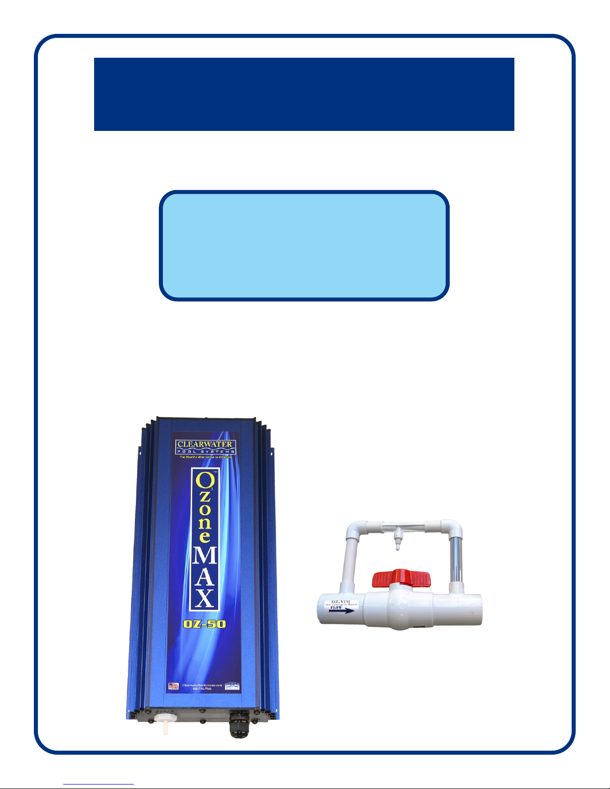
ClearWater OzoneMAX OZ-50 Installation & Operation Manual
TM
OzoneMAX
3
Vacuum-ultraviolet Ozone Systems
Installation
&
Operation Manual
Model
OZ-50
A. Important Safety Instructions
IMPORTANT SAFETY INSTRUCTIONS
When using this electrical equipment, basic safety precautions
should always be followed, including the following:
READ AND FOLLOW ALL INSTRUCTIONS
in this manual before attempting installation.
• A wire connector is provided on this unit to connect a minimum 12 AWG solid copper conductor between this unit and
any metal equipment, metal enclosures of electrical equipment, metal water pipe, or conduit within five (5) feet (1.5m)
of the unit.
• Follow all applicable electric codes.
• All permanent electrical connections should be performed by a qualified electrician.
• For cord and plug connected units:
“Risk of electric shock. Connect only to properly grounded, grounding type receptacle.”
• For cord and plug connected units:
“Do not bury cord.”
• For cord and plug connected units:
“Warning – To reduce the risk of electric shock, replace damaged cord immediately.”
• If electrically connecting this unit directly to pool controls, ensure the controls are protected by a (G.F.C.I.) Ground Fault
Circuit Interrupter.
• Install at least five (5) feet from wall of pool water using nonmetallic plumbing. Install ozone generator no less than one
(1) foot above the maximum water level to prevent water from contacting electrical equipment.
Install in accordance with the installation instructions.
• Mount the unit so that it is not accessible by anyone in the pool.
• Electric Shock Hazard. Disconnect unit from power source before attempting service.
• WARNING: Short term inhalation of high concentrations of ozone and long term inhalation of low concentrations of
ozone can cause serious harmful physiological effects. Do not inhale ozone gas produced by this device.
• WARNING: UV Light is harmful to eyes and exposed skin. Do not look directly at the Ozone producing bulb used in
this device.
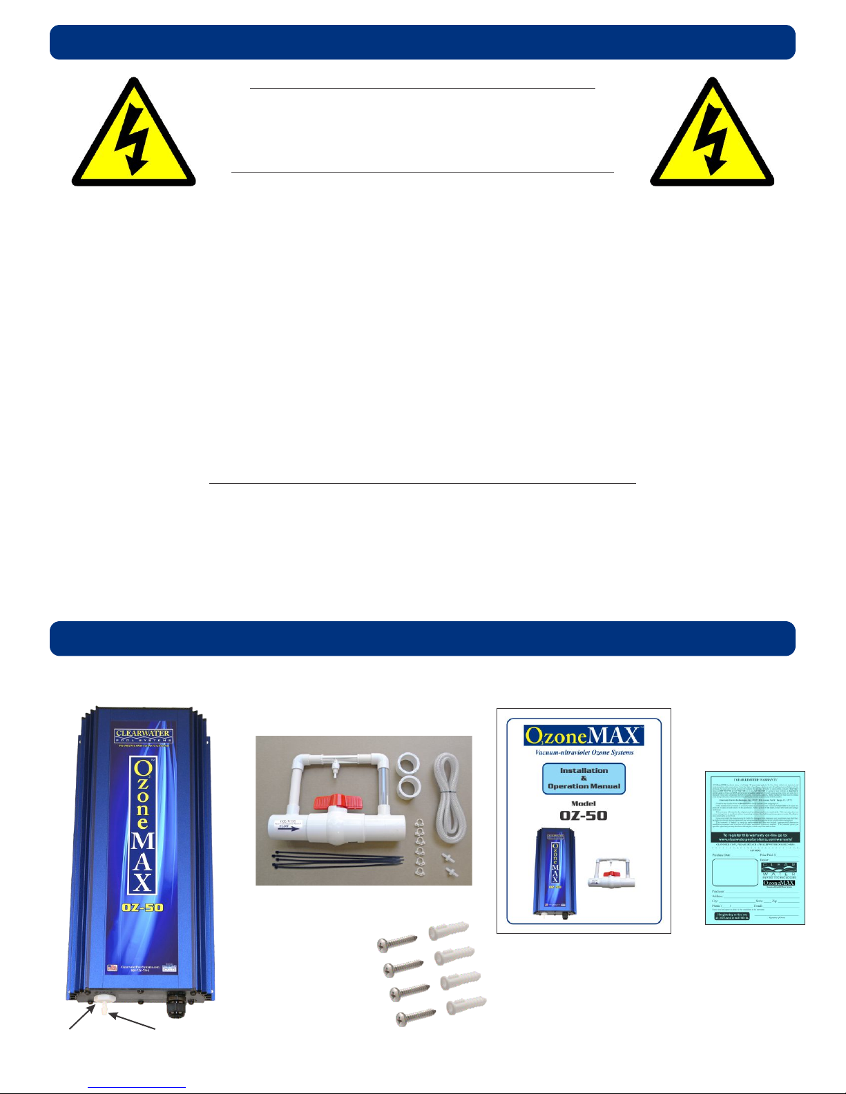
B. Identifying OzoneMAX components
OZ-50
Power Box
OZ-VIM
Venturi Injection Kit
with Manifold
Owners
Manual
Warranty
Card
4 Piece Molly Set
with #10 Screws
Indicator
Light
Output
Connector
2
C. Tools & Materials Required
• Bullet Level • Drill & Drill Bits
• Hacksaw or Pipe Cutter • PVC Cement
• PVC Cleaner/Primer • Utility Knife
• Screwdrivers, Flat & Phillips • Screws & Anchors
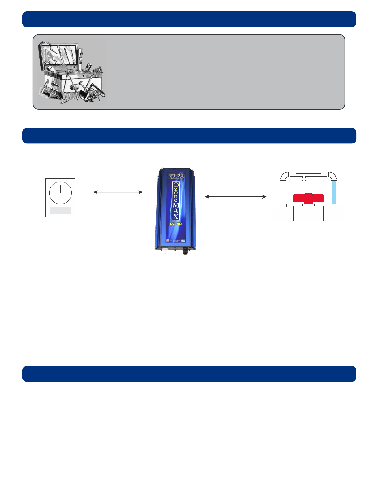
D. Site Survey
Power Source/
OzoneMAX Unit
Venturi Injector
TimerBox
within 6 feet
The OzoneMAX system is comprised of a power box and a venturi injection kit with manifold, which
needs to be installed at the very end of the return line (after the filter, ionizer electrode chamber,
heater, etc.).
The ozone unit will need to be installed to a post or wall within six (6) feet of a 115 or 220VAC timer,
electrical box or a 115V receptacle. This location will need to be within eight (8) feet of location of the
venturi injector. This location should be mounted at least one (1) foot above maximum water level
and preferably out of direct sunlight. The ozone unit should be no closer than five (5) feet from a
body of water.
within 8 feet
E. Installing the Power Box
Mount the OzoneMAX unit to a post or wall using the four mounting screw holes in the enclosure
base. The unit may be mounted horizontally or vertically, however it is recommended that the vent
holes not face upward and be directly exposed to rainfall. The location of the box must be within
eight (8) feet of the location of the venturi, which is plumbed on the return line. The unit should be
mounted at least one (1) foot above maximum water level and preferably out of direct sunlight. The
power box should also be located no closer than five (5) feet from a body of water.
It is strongly recommended to add a protective shade cover to keep the unit out of direct
sunlight if possible.
3
 Loading...