

Page 1
Installation Manual
Universal Kit
Krista LED Light Kit
Dimmable
Page 2
Page 2
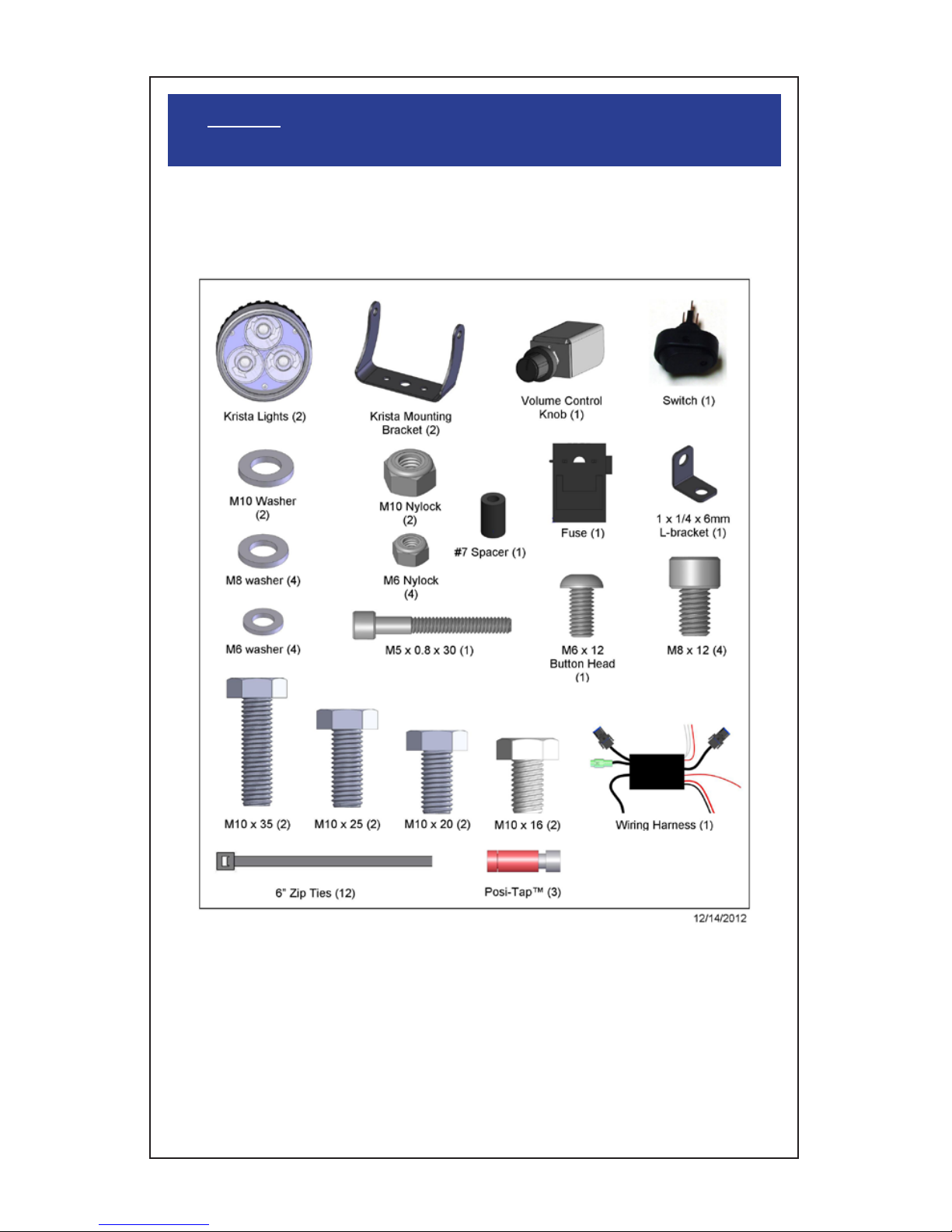
Step 1: Parts List and Bike Preparation
• Check Parts list below with your kit to be sure all parts are handy. If
something is missing, please call us at (916) 852-7029.
Please be sure to read our instructions thoroughly
before attempting installation.
Please take the time to review the included instructions. Installation
of the new Clearwater Krista Lights is straightforward. But, be sure to
follow some of the suggestions to keep the installation safe and reliable.
If you have any questions or comments, please feel free to contact us.
Thank you!
Page 3

Page 3
Step 1: Parts List and Bike Preparation
Bike Preparation:
• First, park the motorcycle on hard pavement or concrete to insure the
bike will be stable during the installation. If you can mount the bike on a
stand with tie-down straps, this will help secure the motorcycle.
• Follow the manufacturers guidelines for disconnecting the battery. This
is important to prevent damage to the electrical system.
• Krista is a very bright LED auxiliary light. It uses advanced digital
circuits to monitor and control light output. Do not use these with on
coming traffic unless the dimmer is turned down all the way. Krista
is designed as an off road only light due to it’s light output and beam
pattern. The wide circular pattern is very useful in mountain roads on a
motorcycle as it keeps light on the road and in the tree canopy. As the
bike leans, light is still focused on the road. Be certain to use the lights
in a manner that does not blind oncoming traffic. Use these with caution
and ride safe.
Krista Technical:
Krista is a very bright LED light that uses digital drivers to produce
very efficient light from (3) 12 watt LED’s. By using a proprietary digital
volume control, we can “dim” the lights via a remote mount volume
control. This rotary knob sends a digital signal to our microprocessor
that changes the pulses of electricity to the LED’s. As we increase the
time that the lights are “off” the human eye perceives this as dimming.
We switch our lights on and off at a rate of 250 times per second, every
second. Increased efficiency occurs with the dimming as well. Krista can
also be used in a “low” beam mode and a “high” beam mode. The factory
handlebar high beam switch is used to select the two different Krista
modes. Light output approaches that of a 150 watt halogen bulb while
only using 35 watts of power. Krista is easy to install and has many,
many uses. Krista is also serving overseas as an emergency operating
room light on a remote island hospital.
Installation Tips:
There are two main parts to the installation of your new Clearwater
Lights. The mechanical portion, and the electrical portion. With this
manual, we will go over the basics of both which should allow you to get
your lights up and running. If you purchased a bracket made specifically
for your bike, refer to our manuals online at www.clearwaterlights .com
for that specific installation.
Page 4
Page 4
Step 2: Mounting The Lights / Crash Bar Mount
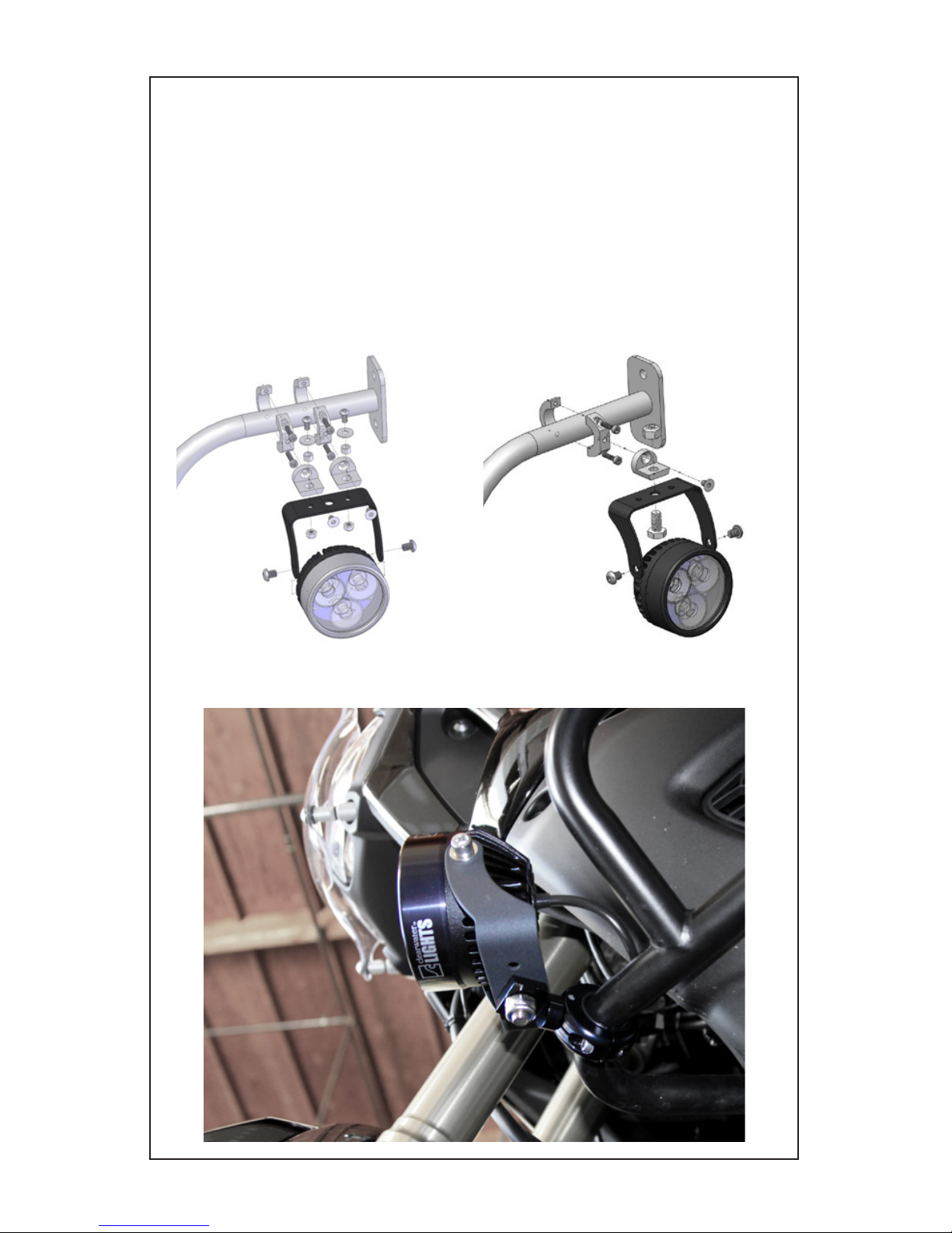
Mounting The Lights: (Crash Bar)
• Mounting the Krista to the Crash Bar is very simple. Pre-assemble
the lights, and mounting bracket loosely with the supplied parts. Locate
where you would like the light to be pointing and the orientation of either
on top or hanging below the bar. Snug the bolts on the clamp so you
can now adjust the alignment of your lights. When using the M10 single
mount, you can adjust the light left and right allowing a wider range of
motion and sight. Use the M6 double clamp mount when wanting a more
rigid and straight aimed light set up.
M10 Single MountM6 Double Mount
Page 5

Page 5
Step 2: Mounting The Lights / Light Bar Mount
Mounting The Lights: (Light Bar)
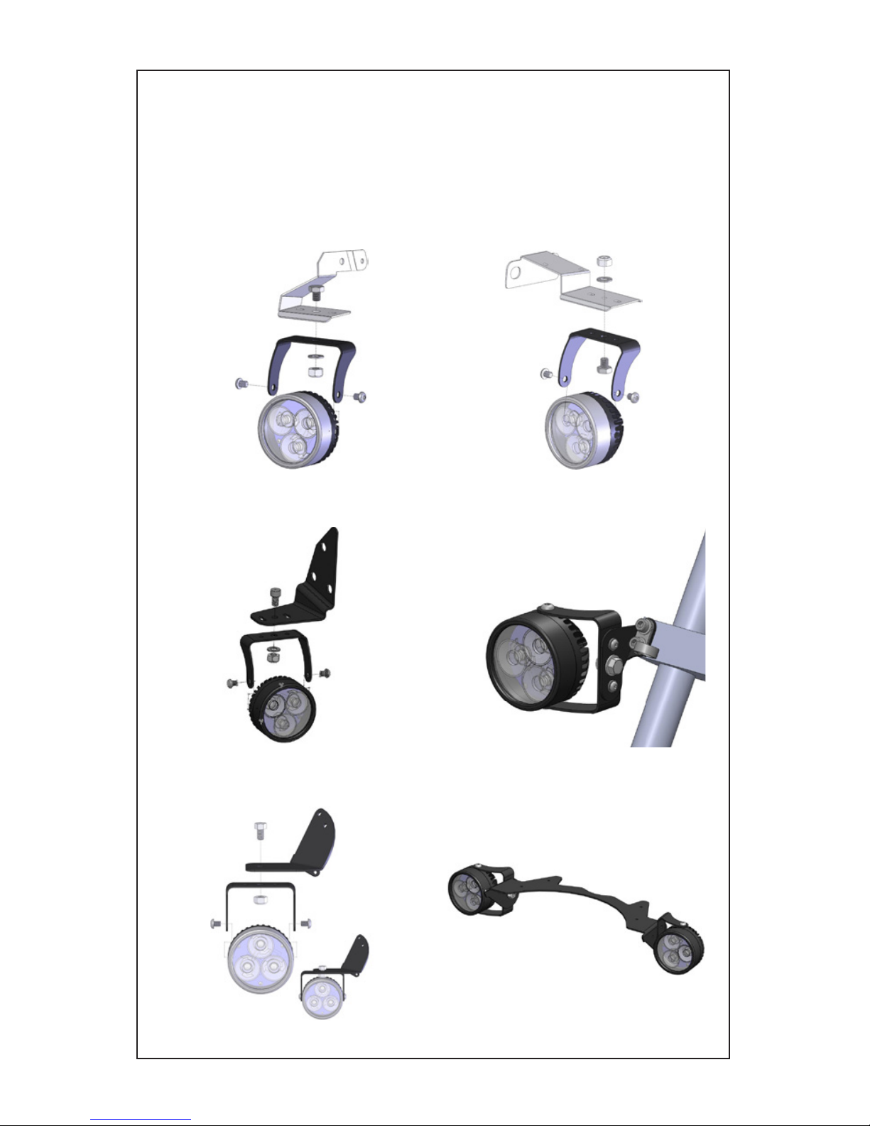
• Krista comes with an assortment of stainless steel bolts that can allow
a variety of installations. A light bar is the easiest installation. Select the
correct bolt to fit your bar. Some mounting bars are stamped sheet metal
and will need a shorter bolt. Krista comes with a mounting bracket that
has two different bolt patterns to match some popular lighting mounts.
Pre-assemble the lights, mounting bracket, shoulder washers and
spacers with new bolts. If you are mounting to a billet light bar, you may
need to add a few of the supplied washers to space our bracket away
from the light bar. Gently screw all bolts in hand tight. Inspect the bolt
length and spacer alignment before tightening the bolts.
Quad MountDouble Mount
Page 6
Page 6
Step 2: Mounting The Lights / Specific Bracket Mount
Mounting The Lights with Model Specific Brackets:
• We have a variety of brackets available for specific bikes where the
standard light bar and crash bar mounts do not allow for the installation of Clearwater Lights. Below are images of some of the more
popular brackets we offer. You can download a specific manual online at our website www.clearwaterlights.com/manuals if needed.
BMW 1200RTBMW LT
Yamaha FJR BMW F650-800GS
Kawasaki Concours Suzuki DR650
Page 7

Page 7
Step 3: Mounting The Volume Control Knob
Mounting The Volume Control Knob: (Bar Mount)
• Mount the Volume Control Knob to handlebar by using supplied
bracket and bolt to the existing controls.
• Route wires from lights and volume control knob bracket to area
under left side of forks. Connections can be made here and be kept
weatherproof.
Mounting The Volume Control Knob: (Fairing Mount)
• Mount Volume Control Knob in left side faring location. Rubber pulls off
with a little force– use a small screwdriver to pry if necessary. Hold box in
your hand. The 10mm nut underneath removes. Drill appropriate hole in
fairing panel (double check location for room behind the panel...) Insert
volume control knob shaft, secure with washer and nut. Re attach knob with
sweep range at 7:00 and 5:00. (Mounting may vary depending on model of
motorcycle.)
• Hint for High Vibration installations: To keep the Volume Control Knob from
rotating itself under high vibration, put a dab of silicone adhesive under the knob
and let it dry. Then push the rubber knob back on. The friction of the glue under
the knob will keep it in place.
Page 8

Page 8
Step 4: Wiring
Electrical:
• Run the Red and Black power wires directly to the battery (non-GSA
version only). The fuse will protect the system in the event of a short.
• Locate the power relay box in a safe location. Secure with a zip tie. It is a
good idea to face the relay box with the wires coming out the bottom. This
helps keep everything dry.
• Route the two Black connectors for the lights to a convenient location
where they will not interfere with steering or any other moving parts.
• Install the switch (non-GSA version only) in a convenient location. Refer to
the sticker on the switch for proper placement.
• Switch - Crimp spade lugs to red, yellow and black wires from relay box.
Attach to corresponding tabs on switch. (See wiring diagram)
• Using Posi-tap, attach red (turn on wire) to a switched 12v wire. See
wiring diagram for your motorcycle.
• Install connectors as shown in the wiring diagram on page 9.
• Note: extra crimp on connectors provided in connection kit for if you would
like to shorten the wires.
High Beam Feature:
• Locate your bike’s High Beam headlight hot (+) lead. This will make
your lights go to full power when you turn on your high beam. Use a
Posi-tap to connect one of the white wires from the relay box to this wire.
It does not matter which white wire you use; both trigger the same way. If
you do not want to use this feature, simply tuck the white wire away in a
neat fashion.
Horn Feature:
• Locate the Horn’s hot (+) lead. This will make your lights flash to
full when you sound your horn. Use a Posi-tap to connect one of the
white wires from the relay box to this wire. It does not matter which
white wire you use; both trigger the same way. If you do not want to
use this feature, simply tuck the white wire away in a neat fashion. See
addendum for ground switching bikes.
Wire Routing: (Please consult owners manual for wiring diagram and color codes)
• Be sure to route wires so that they cannot become tangled or caught
in either a suspension part or steering part. Check movement of both
steering and suspension before riding the bike.
• It is sometimes helpful to follow existing wire routing.
Page 9
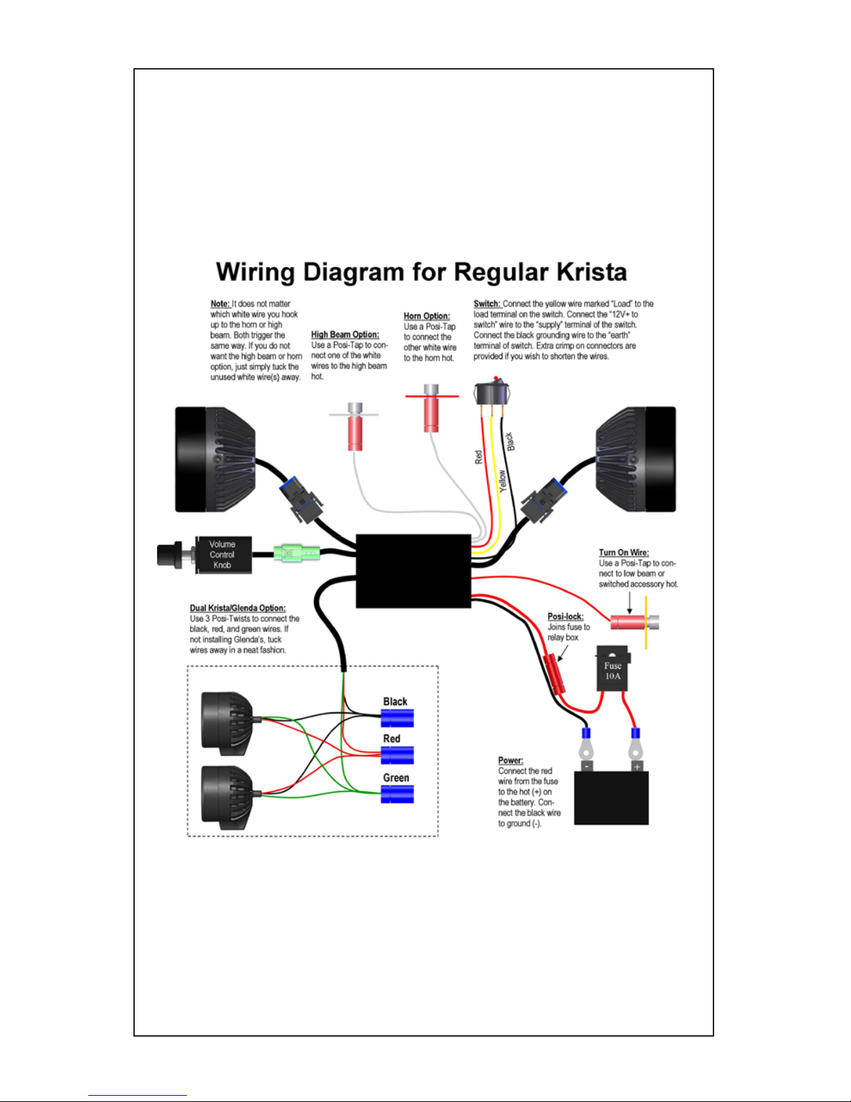
Page 9
Step 4: Wiring
4//2012
Page 10

Page 10
Step 5: Alignment / Drip Loop Instructions
Aligning The Lights:
• As Krista is designed as an auxiliary light, adjustment is up to the
user depending on his needs. Ask an assistant to help you with this
procedure. Make sure the bike is on level ground and have an assistant
sit on the bike. With a right angle board or object, position the board on
the floor and slide it up to the light. The goal is to adjust the lights so that
the light is level with the ground. Passengers and luggage may alter the
alignment of the light, so further adjustments may be needed. You may
find that a slight downward angle (5 degrees) is helpful. Often times it is
helpful to angle the right side light toward the right side of the road. This
helps with identifying road terrain and potential critters.
No Drip Loop
With Drip Loop
Using a Drip Loop
• Though our lights are sealed for ultimate all weather use, sometimes water
sneaks by. To make sure this doesn’t happen, we highly suggest using a drip loop.
When installing the wiring to your lights, use a drip loop as shown below. This will
keep water from dripping directly into the light and instead fall off before it can
reach the back of the body.
• To do this just leave a bit of extra wiring and let it hang below the light. You
could make a complete loop if you like, but just make sure the wire hangs below
the light as shown below.
Page 11

Page 11
Posi-Twist (A):
1. Strip all wires to be inserted 3/4”.
2. Twist all wires together.
3. Completely unscrew the top from the Posi Twist.
4. Feed the twisted wires through the bottom portion of the Posi-Twist.
5. While ensuring the wires do not slip out of the bottom of the Posi-Twist,
attach the top and tighten.
Posi-Tap (B):
1. Unscrew the cap of the Posi-Tap (gray or large end).
2. Slide the wire you wish to tap into through the slot in the cap.
3. Re-attach the body of the Posi-Tap and tighten.
4. Attach the other wire to the bottom using the same method as a Posi-Twist.
Posi-Lock (C):
Attach the wires to the screw in connectors using the same method as
Posi-Twists.
A B C
Posi-Products Installation Instructions:
Notes:
Page 12

Thank you for purchasing your Clearwater lights. We hope this product
will help make you a safer rider. Please feel free to send us comments
or suggestions at any time. We learn from you. Visit our website for more
exciting products to help you see better at night.
Ride safe!
Sincerely,
Glenn and the team at Clearwater.
The Clearwater Company | 2546 Mercantile Dr. Ste B | Rancho Cordova, CA 95742
Phone: (916) 852-7029 | Fax: (916) 852-9410 | www.clearwaterlights.com
Version 7.5 | 12/14/12
 Loading...