

ClearWater HDO3-I, HDO3-III, HDO3-II Installation & Operation Manual
Ozone Systems
Installation & Operation Manual
HDO3 Series
High Dissolved Ozone Generation System
ClearWater Tech, LLC.
Integrated Ozone Systems
850-E Capitolio Way, San Luis Obispo, Ca 93401 • 805-549-9724 • Fax: 805-549-0306 • E-mail: service@cwtozone.com • www.cwtozone.com
Copyright © 2005 - ClearWater Tech, LLC • Reproduction of any kind is prohibited • LIT210 • REV121605
1
THEORY OF OPERATION/PRODUCT DESCRIPTION CHAPTER 1
The HDO3 Series systems are a complete, advanced ozone delivery system and engineered to efficiently produce high
levels of dissolved ozone in water of municipal quality or better. The HDO3 system takes water from a clean water
source, re-pressurizes it, injects ozone to the water, then allows contact time under pressure to achieve maximum ozone
solubility. Equipped with an integrated dissolved ozone monitor/controller, this system can be regulated to achieve most
desired dissolved ozone levels required. Each complete, integrated system includes the components required for reliable,
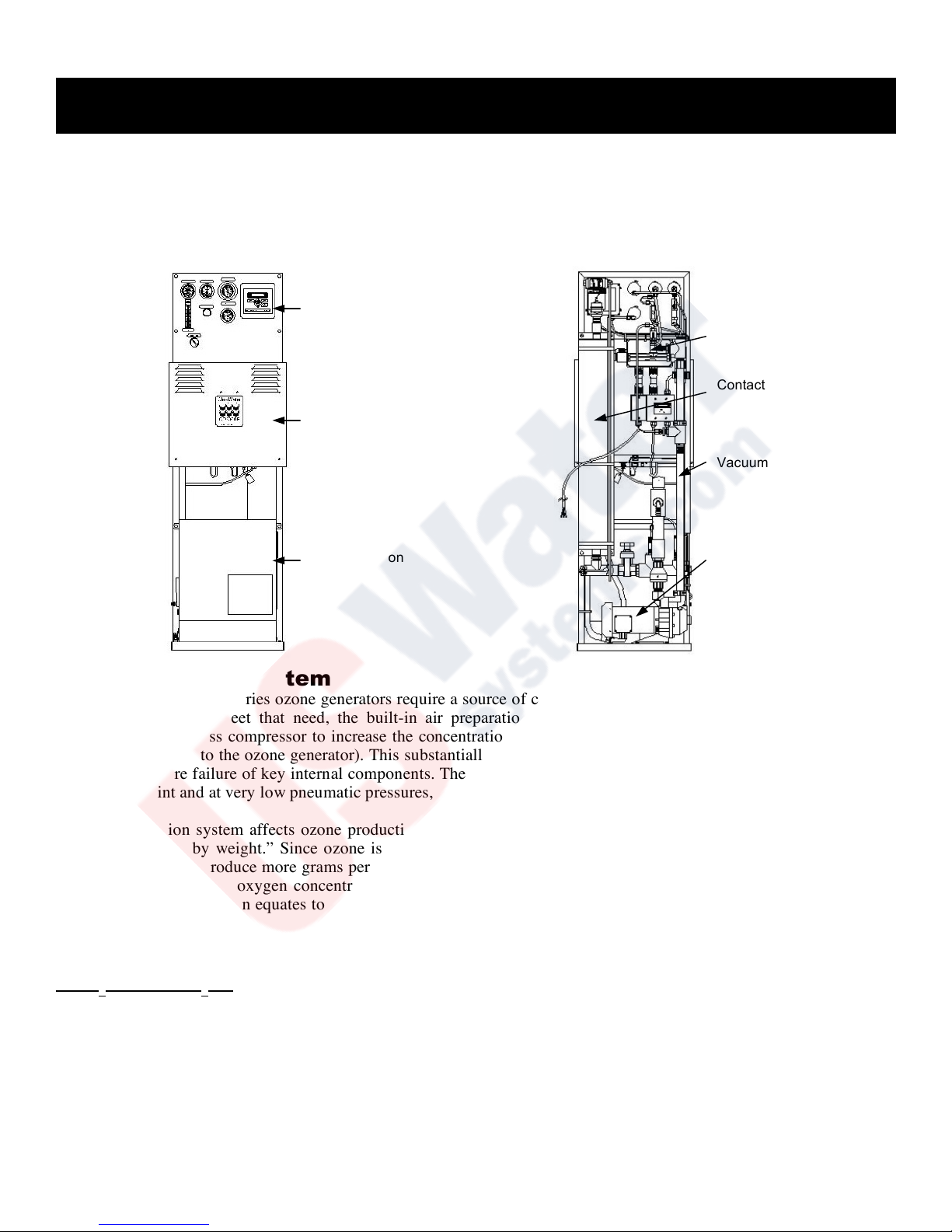
efficient ozone production and can be divided into four general segments:
• Air Preparation System • Ozone Generator • Ozone Injection/Contacting • Control Panel
Air Preparation System
ClearWater Tech HDO3 Series ozone generators require a source of clean, dry, oil-free, oxygen-enriched air for effective
ozone production. To meet that need, the built-in air preparation system employs pressure swing adsorption (PSA)
technology with oil-less compressor to increase the concentration of oxygen and reduce the moisture content in the feed
gas (the air supplied to the ozone generator). This substantially improves the output capability of the ozone generator and
prevents premature failure of key internal components. These air preparation systems deliver 90%+/-3% oxygen purity at
-100°F dew point and at very low pneumatic pressures, minimizing noise and reducing compressor wear.
The air preparation system affects ozone production in grams per hour and more importantly ozone concentration, also
known as “percent by weight.” Since ozone is produced with oxygen, the greater the percent of oxygen that enters the
ozone generator will produce more grams per hour and concentration of ozone. Since the HDO3 Series ozone generation
systems incorporate PSA oxygen concentrator they will yield the highest grams per hour at the highest concentrations.
Greater ozone concentration equates to higher solubility of the ozone gas in solution, which will yield a greater dissolved
ozone level.
Ozone Generator
HDO3-I and HDO3-II - Only:
The ClearWater Tech HDO3-I is equipped with a CD12 ozone generator where as the HDO3-II is equipped with CD2000
ozone generator. The oxygen feed gas produced by the air preparation system is supplied to the ozone generator at a
maximum pressure of 5 pounds per square inch (psi). It then flows into the built-in air flow meter; at this point, the feed
gas is mostly drawn through the ozone generator by the vacuum created at the ozone injector - rather than by the pressure
from the air preparation system compressors. A stainless steel needle valve, located on the control panel of the HDO3-I
and HDO3-II, is used to maintain optimum pneumatic parameters inside the ozone reaction chambers. The ozone
generator is equipped with vacuum switch, which prevents ozone production if vacuum is lost within the ozone reaction
chambers.
Control Panel
Ozone Generator
Air Preparation
Injector
Contact Tank
Vacuum Break
Booster Pump

Theory of Operation/Product Description (continued)
2
HDO3-III - Only:
The HDO3-III system is equipped with a ClearWater Tech CD2000P ozone generator designed to supply high
concentrations of ozone gas at 10 PSI. The oxygen feed gas produced by the air preparation system is supplied to the
ozone generator, which flows through the built-in flow meter. A stainless steel needle valve, located on the control panel
of the HDO3-III, is used to maintain optimum pneumatic parameters inside the ozone reaction chambers. After this point
the vacuum created at the ozone injector draws the ozone gas into the water line. The ozone generator is equipped with a
pressure switch, which prevents ozone production if pressure within the ozone reaction chambers drops below 9 PSI.
The feed gas of the HDO3 systems enters the fused, thermally-protected reaction chambers inside the ozone generator;
some of the oxygen molecules are split while passing through the high voltage electrical field (the “corona”), forming
single oxygen atoms (O 1). These oxygen atoms then recombine with other oxygen molecules in the air stream, forming
ozone.
Ozone Injection/Contacting
The ozone injector serves two purposes: One, it creates the vacuum
required to safely draw the ozone gas from the ozone generator and
two, it provides a means by which the ozone gas can become
dissolved in water. A very dynamic injection process is required to
effectively dissolve ozone in water.
ClearWater Tech HDO3 systems use only Mazzei® injectors for
maximum mass transfer efficiency. The injector produces a
cavitation effect, enabling the ozone gas to join the water stream in
the form of extremely tiny bubbles. These bubbles must be as
small as possible in order to increase the ratio of bubble surface
area to the amount of ozone entering the water.
Incorporated on the HDO3 systems is a stainless steel contacting vessel and auto vent to provide sufficient contacting of
the ozone gas with the water and off-gas any residual ozone. By design, the operating water pressures of this system and
the ClearWater Tech engineered contacting system allows for high levels of dissolved ozone to be maintained in the water
in this single pass configuration.
The HDO3 systems incorporate a water pressure relief valve and positive atmospheric vacuum break as standard safety
equipment to protect the system. This water-pressure relief valve is located downstream of the dissolved ozone sensor and
is set to relieve at 55 PSI. If excessive backpressure is applied to the system this relief valve will open protecting the
dissolved ozone sensor. The vacuum break is located on the backside of the HDO3 system and is a positive atmospheric
break between the ozone injector and ozone generator. If the ozone injector check valve were to fail water would flow
back to the vacuum break and out to drain instead of back to the ozone generator.
Control Panel
The HDO3 systems incorporate a user-friendly instrumentation control panel, which includes; ozone generator oxygen
flow meter, ozone generator vacuum or pressure gauge, injector vacuum gauge, high water pressure gauge, low water
pressure gauge, stainless steel injector vacuum control valve and a dissolved ozone parts per million (PPM)
monitor/controller. This dissolved ozone monitor/controller can be used to monitor the dissolved ozone level produced
and can be set up control the ozone generator output via a 4-20mA output signal, other alarm relays are also available on
the monitor/controller.
Ozone Destruct
The ClearWater Tech off-gas destruct systems (offered separately), consists of two components the ozone destruct unit (a
heated chamber filled with manganese dioxide and copper oxide) and a water trap. Used in conjunction with a ClearWater
Tech off-gas vent, the ozone destruct system is an effective way to vent the contact vessel when it is impractical to send
the off gas to atmosphere or reintroduce it to the water. See the “Ozone Off-Gas Destruct” manual for installation and
maintenance procedures.
3
SAFETY INFORMATION
CHAPTER 2
SAFETY WARNINGS
Two aspects of ClearWater Tech dissolved ozone systems represent potential dangers – ozone gas and high voltage
electricity.
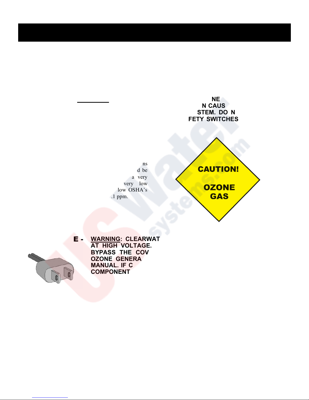
OZONE GAS -
WARNING: HIGH CONCENTRATIONS OF OZONE GAS ARE DANGEROUS
TO HUMANS. LOW CONCENTRATIONS CAN CAUSE IRRITATION TO THE
EYES, THROAT AND RESPIRATORY SYSTEM. DO NOT TAMPER WITH
OR DELIBERATELY BYPASS THE SAFETY SWITCHES BUILT INTO THE
OZONE GENERATOR.
The Cl earWat er Tech HDO3 Seri es co rona
discharge ozon e systems are designed to operate under
a vacuum or pressure condition. While safety precautions
have been taken, entering the equipment area should be
avoided if ozone gas is detected. Ozone has a very
distinctive odor and is detectable at very low
concentrations (0.02 ppm), which is far below OSHA’s
maximum permissible exposure level of 0.1 ppm.
HIGH VOLTAGE -
WARNING: CLEARWATER TECH OZONE GENERATORS OPERATE
AT HIGH VOLTAGE. DO NOT TAMPER WITH OR DELIBERATELY
BYPASS THE COVER OR SAFETY SWITCHES BUILT INTO THE
OZONE GENERATOR UNLESS INSTRUCTED TO DO SO BY THIS
MANUAL. IF CONTACT IS MADE WITH OPERATING HIGH VOLTAGE
COMPONENTS, ELECTRIC SHOCK WILL OCCUR.
ClearWater Tech HDO3 Series systems operate with line voltage. The incorporated corona discharge ozone generators
take line voltage and convert it DC current. A high voltage transformer then boosts the voltage. While each ozone
generator has a cover safety switch and other safety interlocks, proper care must be used by a qualified electrician when
making any internal adjustments or performing any maintenance procedures.

4
IMPORTANT SAFETY INSTRUCTIONS
When installing and using this electrical equipment, basic safety precautions should always be followed, including the
following:
1.
READ AND FOLLOW ALL INSTRUCTIONS.
2.
SAVE THESE INSTRUCTIONS.
3.
All electrical connections should be made by a licensed, qualified electrician.
4.
Before attempting any electrical connections, be sure all power is off at the main circuit breaker.
5.
Install all electrical equipment at least five feet from any open body of water using non-metallic plumbing.
6.
Install check valves to prevent water from contacting the electrical equipment.
7.
The electrical supply for this product must include a suitably rated switch or circuit breaker to open all
ungrounded supply conductors to comply with Section 422-20 of the National Electrical Code, ANSI/NFPA
70-1987. The disconnecting means must be readily accessible to the operator(s) but installed at least five
feet from any open body of water.
8.
Be sure to bond (ground) the system using the copper-bonding lug on the bottom front panel of the Ae
system. The system should be bonded with solid copper wire conforming to all local, state and national
electrical codes.
9.
The system should be sized appropriately for its intended use by a qualified professional familiar with the
application. This equipment must be validated by the manufacturer for its intended use; failure to do so
may void the warranty.

5
INSTALLATION PROCEDURES -
Getting Started
CHAPTER 3
Unpacking
Compare the ozone system equipment received to the packing list provided. Before beginning any
installation procedures, thoroughly inspect all components for damage. If damage is noticed,
promptly notify the freight carrier and request an on-site inspection. Inspect all packing materials for
small parts before discarding. Inspect all plumbing, fittings and tubing for packing material that may
have become lodged in openings.
Equipment Placement
• When placing the ozone system on the equipment pad, make sure to consider safety, maintenance requirements,
local building and fire codes, etc. The components should be easily accessible by the operators, including
equipment access doors and electrical hook-up boxes. All meters, gauges, indicator lights and switches should be
visible and accessible. Dimensional drawings of the HDO3 Series systems are included in Section A of the
Appendix.
• Like any electronic component, performance and longevity is enhanced by favorable operating conditions. Also,
since the air preparation system and ozone generator is air-cooled, a relatively dust-free, well-ventilated area is
required. No caustic chemicals should be stored in the area surrounding the equipment. A minimum clearance of
six inches from the vents on either side of the ozone generator is required.
• The equipment is heavy and requires proper support. Therefore, a clean, dry, level surface should be provided for
the HDO3 Series systems.
• The HDO3 Series systems are designed for specific voltage requirements and to withstand typical outdoor
elements, though should not be subjected to outdoor extremes including contact with water and/or temperature
extremes. Therefore, the equipment must be installed in an environment consistent with the following operating
parameters:
• Ambient temperature range: 20°F to 95°F continuous. If the temperature around the equipment
consistently exceeds 95°F, additional air-cooling must be provided.
• Humidity: 0 - 90% relative humidity, non-condensing environment.
• Line voltage: +/-10% of rated input
Note: Equipment installed in extreme environmental conditions will void manufacturer's warranty.
Water Quality
• For anticipated results the HDO3 Series systems require a source of clean water and free of any contaminate load,
which may include but not limited to:
- Bacteria
- Viruses
- Algae
- Iron
- Manganese
- Chlorine
- Hydrogen Sulfide
- Nitrates
- Nitrites
- pH below 7.0 or above 7.5
- No particulate matter – Pre-filtration is required for
any water supply that has particulate mater.
6
INSTALLATION PROCEDURES – Plumbing CHAPTER 4
The HDO3 system anticipated results are based on water quality and gallons per minute (GPM) flow rate
and water pressure. Based on desired dissolved ozone levels measured in parts per million (PPM), the
system should be plumbed using either a sidestream or full flow configuration, see Figure 4-1 for desired
ppm level at the suggested gpm flow rate. The sidestream method takes a portion of the water from the
main flow (see Figure 4-2) and diverts it into a sidestream through the HDO3 system, then returns the
water back into the full flow. In a full flow configuration, the water is simply plumbed into the HDO3 system, and then
out of the system to the point of use, see Figure 4-3. Note: The HDO3 Series systems have specific flow through rates
that must not be exceeded. If the full flow GPM flow rate exceeds the maximum flow through rate of the HDO3
system the sidestream configuration must be used, see Figure 4-1. Dissolved ozone levels may decline from the
anticipated result listed in Figure 4-1, if the system inlet water pressure is less than 20PSI.
NOTES:
• Adequate use of unions and isolation valves is
strongly recommended to facilitate maintenance
and repairs.
• Use Schedule 80 PVC for all plumbing connections
wherever possible. Plumbing size requirements
are dictated by the water flow characteristics of
the system.
• Make sure to use proper plumbing practices and
secure all plumbing and system equipment
according to local codes.
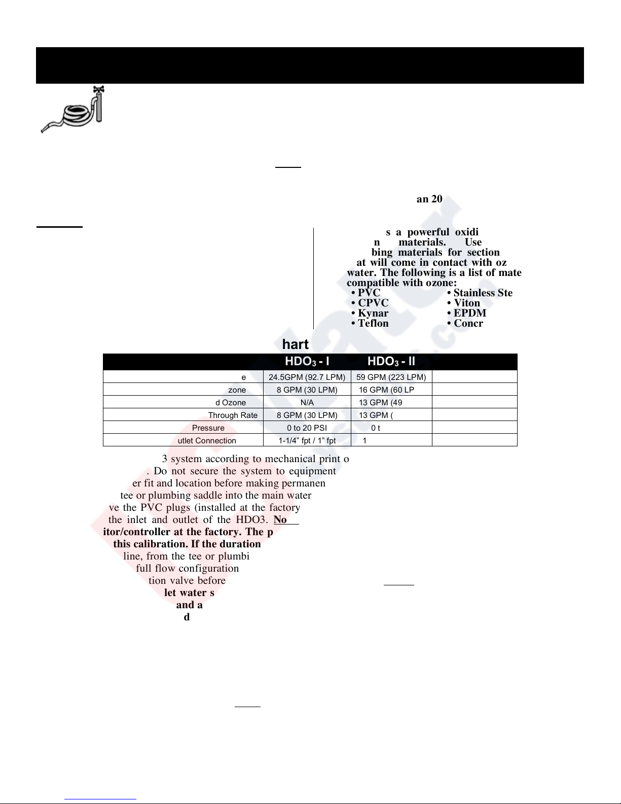
• Ozone is a powerful oxidizer and will degrade
certain materials. Use ozone-compatible
plumbing materials for section(s) of the system
that will come in contact with ozone dissolved in
water. The following is a list of materials that are
compatible with ozone:
• PVC • Stainless Steel (300 series)
• CPVC • Viton
• Kynar • EPDM
• Teflon • Concrete
Hydraulic Specifications Chart Figure 4-1
HDO3 - I
HDO3 - II
HDO3 - III
GPM @ 1.0 PPM Dissolved Ozone
24.5GPM (92.7 LPM)
59 GPM (223 LPM)
150 GPM (568 LPM)
GPM @ 3.5 PPM Dissolved Ozone
8 GPM (30 LPM)
16 GPM (60 LPM)
50 GPM (189 LPM)
GPM @ 4.5 PPM Dissolved Ozone
N/A
13 GPM (49 LPM)
30 GPM (113 LPM)
Minimum & Maximum Flow Through Rate
8 GPM (30 LPM)
13 GPM (49 LPM)
13 GPM (49 LPM)
Min/Max Inlet Pressure
0 to 20 PSI
0 to 20 PSI
0 to 20 PSI
Water Inlet/Outlet Connection
1-1/4” fpt / 1” fpt
1-1/4” fpt / 1” fpt
1-1/4” fpt / 1” fpt
Step 1: Arrange the HDO3 system according to mechanical print or as dictated by equipment layout and serviceability
considerations. Do not secure the system to equipment pad at this point. Dry fit plumbing as appropriate to
insure proper fit and location before making permanent connections.
Step 2: Install a tee or plumbing saddle into the main water line for the sidestream configuration (see Figure 4-2).
Step 3: Remove the PVC plugs (installed at the factory to keep the dissolved ozone probe wet during transportation)
from the inlet and outlet of the HDO3. Note: The dissolved ozone probe is calibrated to the dissolved
monitor/controller at the factory. The probe must not be out of water for more than a 24-hour period to
retain this calibration. If the duration exceeds 24 hours re-calibration may be required.
Step 4: Plumb a line, from the tee or plumbing saddle for the sidestream configuration or from the main water supply
line for the full flow configuration, to the HDO3 booster pump. For serviceability of the equipment be sure to
install an isolation valve before the HDO3 system booster pump. Notes: A pressure reducing valve may be
required if the inlet water supply pressure is greater than 20PSI. The full flow configuration can also be
used to re-circulate and atmospheric vessel, although the HDO3 system must have a flooded suction to the
inlet of the integrated booster pump. If the HDO3 system operates with out water flow damage may
occur to the booster pump and warranty will be void.
Step 5: Using a tee or plumbing saddle, plumb from the outlet of the HDO3 back into the main water line for the
sidestream configuration or to the point of use for the full flow configuration. For serviceability of the
equipment be sure to install an isolation valve after the HDO3 system.
Step 6: Secure the HDO3 system to solid mounting surfaces using appropriate hardware and according to local codes.
Step 7: Depending on conditions, the vented gas from the contact tank off-gas vent may be directed to an ozone
destruct system or to atmosphere. Note: Do not direct the tubing to the suction side of a pump.
Step 8: The HDO3 system incorporates a water pressure relief valve (located on the water outlet line of the system) set
at 55 PSI, to protect the dissolved ozone probe. If the water pressure downstream of the probe reaches 55 PSI
the pressure relief valve will open. Plumb a line from the ½” fpt outlet port of the pressure relief valve to waste.
Plumbing (continued)
7
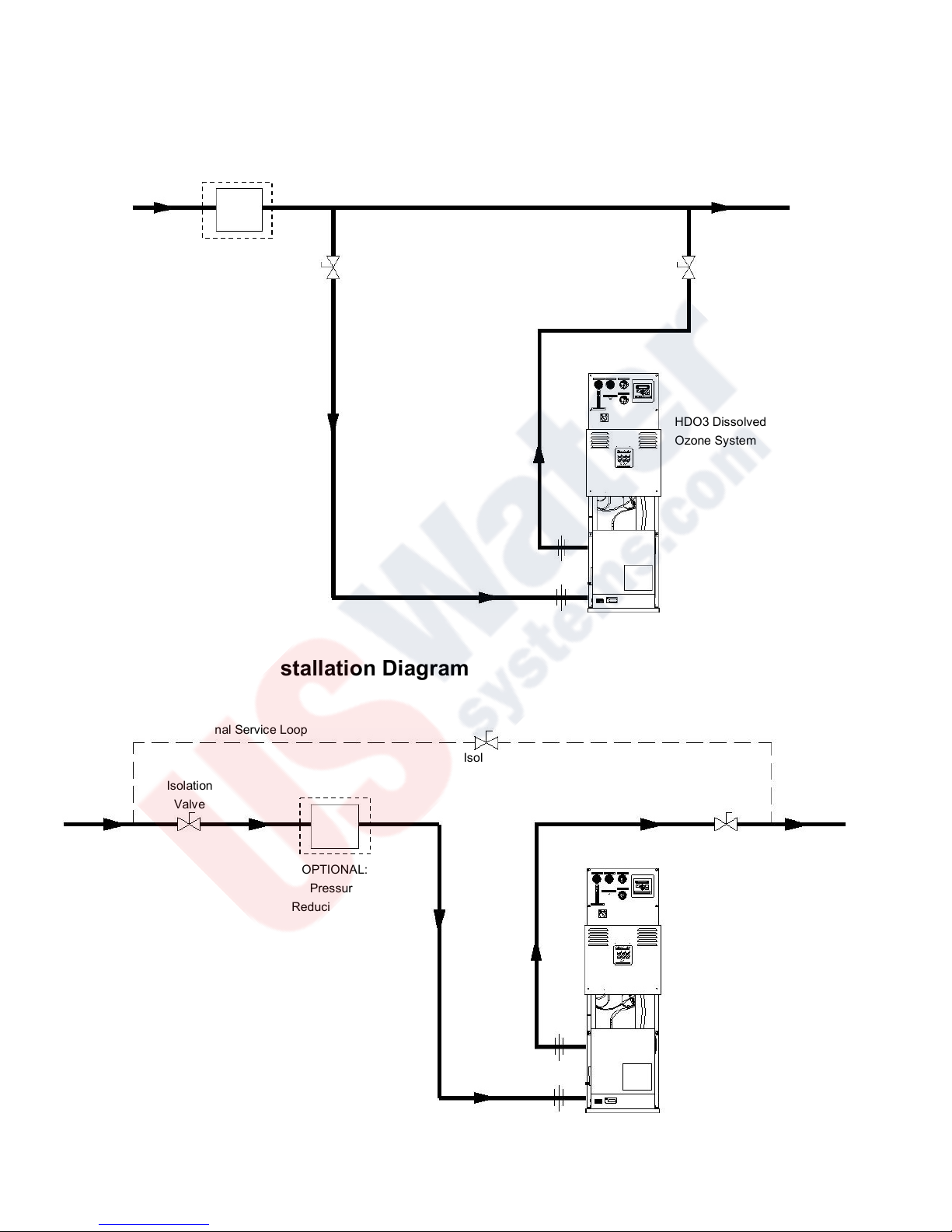
Sidestream Plumbing Installation Diagram
Figure 4-2
Full Flow Plumbing Installation Diagram
Figure 4-3
HDO3 Dissolved
Ozone System
OPTIONAL:
Pressure
Reducing Valve
Optional Service Loop
Isolation
Valve
Isolation
Valve
Isolation
Valve
Isolation
Valve
Main Water Line
Sidestream
Water Line
HDO3 Dissolved
Ozone System
Isolation
Valve
OPTIONAL:
Pressure
Reducing Valve

8
INSTALLATION PROCEDURES –
Electrical
CHAPTER 5
The HDO3 Series ozone generation systems are designed to be hard wired to the main power source with the specific
input voltage requirements. All possible pre-wiring has been completed at the factory. Logic schematics have been
provided in the Appendix - Section D.
NOTES:
• All electrical connections should be made by a
licensed, qualified electrician. All local, state and
national codes must be observed.
• Make sure all power is off at the main circuit
breaker before making any electrical connections.
Step 1: Conforming to all local, state and national electrical codes, ground the HDO3 system to a true earth ground.
Use solid copper bonding wire (usually #8 AWG) from the copper-bonding lug located on the base of the
HDO3 system.
Step 2: Main Power – The systems are equipped with a
12AWG 2-pole/3-wire cord 10 foot in length. Wire the
HDO3 system from the main power cord to the main
power source with specified input voltage, either
120VAC 60Hz (L1-Black, Neutral-White and Ground-
Green), 220VAC 50Hz or 220VAC 60Hz (L1-Black,
Neutral/L2-White and Ground-Green), single phase
(1ø), +/- 10% of rated voltage.
Step 3: External Loop: The external loop is a true dry contact interface. Note: The term ‘dry contact’ means that
this loop does not supply output nor except input voltages. Warning: Supplying voltage to the external
loop will cause damage to the ozone generator and void warranty. Under normal operation, the external
loop will effectively interrupt the ozone output when the loop has lost continuity; this will also illuminate the
LED located on the 4-20mA control board inside the HDO3-II and HDO3-III ozone generators and the EXT
LOOP LED on the front cover of the HDO3-I ozone generator (see Appendix-Section A, for location of 420mA board) and turn off the “Ozone Output” LED(s) on the front cover. Note: When the external loop has
lost continuity main power to the ozone generator will remain “ON” giving power to the cooling fan(s).
When continuity is present through the external loop, ozone output will continue. This continuity will
effectively turn “OFF” the LED of the 4-20mA board and the EXT LOOP LED and will again illuminate the
“Ozone Output” LED(s).
The external loop, a removable two-position plug with a white 18AWG wire located at the bottom panel of the
ozone generator (see Appendix-Section A), can be interfaced to any control device, i.e., pressure switch,
vacuum switch, flow switch, float switch, ORP controller, PPM controller, or timer. To interface a control
device to the external loop, cut the white 18AWG wire in half. Connect the control device to each leg of the
external loop. Note: External Loop control devices supplied by ClearWater Tech may come equipped
with a two-position male connector ready to be plugged into the female two-position connector mounted
to the chassis of the ozone generator. If the control device used supplies an output voltage, a single pole
single throw (SPST) normally-open relay may be used to create a dry contact interface (see Figure 5-1,
“External Loop Electrical Interface”). Note: Attached to the white 18AWG external loop is a warning,
“THIS CONNECTION IS A DRY CONTACT ONLY, DO NOT APPLY VOLTAGE”.
Step 3: Ozone Output Control – The HDO3 Series systems are equipped with two options for controlling the ozone
output, either a manual 0-100% ozone output control or a remote 4-20mA control input signal. See AppendixSection A for location.
1. Manual Ozone Output Control - Turning the control knob counterclockwise will decrease the ozone output down
to 0%, while turning the knob clockwise will increase the ozone output up to 100%. The “Ozone Output” is indicated
by the LED(s) on the front of the ozone generator, see Appendix-Section A.
2. Remote 4-20mA Control: The ozone generator will automatically sense the 4-20mA input signal and override the
setting of the manual ozone output control. Based on the 4-20mA signal, ozone output will increase or decrease,
4mA = 0% ozone output, 20mA = 100% ozone output. The “Ozone Output” is indicated by the LED(s) on the front
of the ozone generator, see Appendix-Section A. Note: If the remote 4-20mA signal fails or is missing, the system
will default to the manual ozone output setting. Check and adjust the manual ozone output control knob to
HDO3 Series Power Consumption
Input
Voltage
120VAC
60Hz
220VAC
50Hz
240VAC
60Hz
HDO3–I
20 amps
11 amps
10 amps
HDO3– II
20 amps
11 amps
10 amps
HDO3–III
20 amps
11 amps
10 amps
Electrical (continued)
9
avoid over-ozonation. The ozone generator 4-20mA control leads of the HDO3 system have been pre-wired at the
factory to the dissolved ozone monitor/controller. The negative (-) input signal to the Purple wire of the ozone
generator and the positive (+) input signal to the Orange wire of the ozone generator. Note: The dissolved ozone
monitor/controller has been pre-programmed at the factory to 20mA or 100% ozone output. Either reprogramming the dissolved ozone monitor/controller or removing the 3-position 4-20mA control connector
from the HDO3 ozone generator can override this function.
Step 4: Dissolved Ozone Monitor/Controller – The HDO3 series systems are equipped with an integral dissolved
ozone monitor/controller. This monitor/controller is equipped with alarm relays that can be used to interlock
other devices based on dissolved ozone levels. Main power and the 4-20mA control interface to the ozone
generator have been pre-wired at the factory. The unit has also been pre-programmed at the factory to supply a
constant 20mA (100%) ozone output signal to the ozone generator. The dissolved ozone monitor/controller
must be re-programmed for any other desired setting. See the dissolved ozone monitor/controller manual for
function and electrical hook-ups.
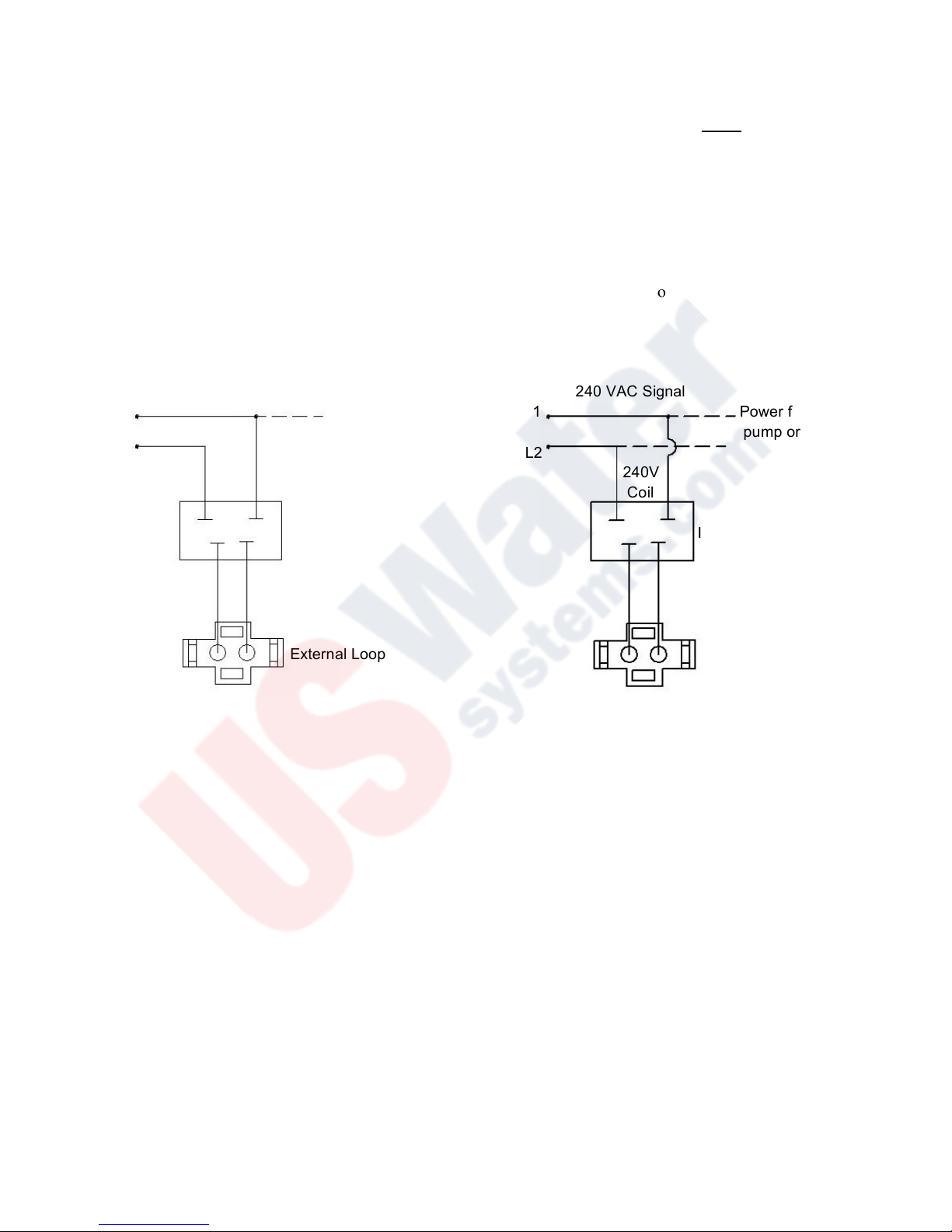
External Loop Electrical Interface
Figure 5-1
120 VAC Signal
L1 Power from ORP, PPM,
pump or timer
N
120V
Coil
Interface Relay
External Loop
240 VAC Signal
L1 Power from ORP, PPM,
pump or timer
L2
240V
Coil
Interface Relay
External Loop

10
START-UP & CALIBRATION
CHAPTER 7
The previous sections of this manual have involved comparatively static procedures – making
electrical connections and fitting pipe, etc. This section involves the dynamic process of starting up
and balancing the components of the system, including initiating water flow, making air and water
flow adjustments, etc.
Maximum performance and reliability is achieved when the prescribed air flow and vacuum or pressure levels are
maintained at the HDO3 system while the ozone injector is operating at a comparatively higher vacuum (measured in
inches of mercury, or “in.Hg”). Also, maintaining the correct water flow and hydraulic pressures will ensure the highest
possible level of dissolved ozone. The air from the air preparation system of the HDO3-I and HDO3-II flows toward the
ozone generator under pressure, and from the ozone generator under vacuum (created by the ozone injector). The change
from pressure to vacuum occurs at the SCFH meter of the air preparation system located on the bottom left side of the
HDO3 system. Where as, the air from the air preparation system of the HDO3-III is flowing through the ozone generator
under pressure, and from the ozone generator under a slight vacuum (created by the ozone injector). The change from
pressure to vacuum occurs after the stainless steel “Ozone Injector–Vacuum Control” needle valve located on the control
panel of the HDO3-III.
HDO3 Series – Dissolved Ozone Generation System
Warning: Disconnect the External Loop dry contact (see Appendix-Section A) from the ozone generator
while performing all start-up procedures. Failure to do so may result in ozone escaping to atmosphere.
Step 1: Make sure all isolation valves in the ozone water system are open (Figures 4-2 and 4-3 show recommended
isolation valve locations).
Step 2: The main power switch of the HDO3 system, located on the Control Panel (see Appendix-Section A), should
be in the “OFF” position. Main power should be available to the HDO3 system.
Step 3: Remove the Fill Port Cap of the vacuum break located on the backside of the HDO3 system and fill the Riser
Tube with clean water (no particulate matter) to the fill level, see Appendix-Section A
Step 4: Re-install the Fill Port Cap, hand tight. Note: Do not over tighten as damage to PVC fittings may occur.
Step 5: Completely open the contact tank backpressure valve, located towards the bottom backside of the HDO3
system (see Appendix-Section A), by turning it counter-clockwise.
Step 6: Start-up hydraulics. Allow the water in the system to reach hydraulic equilibrium (contact vessel full, off-gas
vent operating, etc.) and observe for plumbing leaks. If the inlet water supply is not under pressure be sure the
HDO3 booster pump is flooded with water so that the booster pump will prime. Notes: Water flow must be
established through the HDO3 system booster pump before operation. If the inlet water supply to the
HDO3 system is not under pressure the system may not completely fill with water until the HDO3
system is operational.
Step 7: If the inlet water supply to the HDO3 system is pressurized, using a water pressure regulator with a pounds
per square inch (PSI) gauge, regulate the inlet water supply pressure to 20PSI maximum. Note:
Backpressure downstream of the HDO3 system could affect this PSI reading.
Step 8: Disconnect the green oxygen delivery line from the oxygen concentrator, located on the bottom left-hand side
of the HDO3 system.
Step 9: Turn the main power switch of the HDO3 to the “ON” position. The HDO3 should energize giving power to
the booster pump, oxygen concentrator, ozone generator and dissolved ozone monitor/controller.
Step 10: Adjust the oxygen concentrator flow meter located on the bottom left-hand side of the HDO3 system. This
standard cubic feet per hour (SCFH) air flow meter must be set to atmospheric pressure. See the “Air
Preparation Air Flow” line of the Operating Parameters chart Figure 7-2 for the set point of each HDO3
system. Note: When the system is in normal operation the SCFH flow meter setting may drop due to
backpressure through the system. Do not re-adjust the flow meter.
Step 11: Reconnect the green oxygen delivery line to the oxygen concentrator, which was removed in Step 7 above.
Step 12: Switch the ozone generator power switch to the “ON” position located on the bottom of the ozone generator,
see Appendix-Section A.
Step 13: If the inlet water supply to the HDO3 system is under pressure, slowly close the contact tank backpressure
valve until the needle of the “Low Pressure – Side Water” gauge reaches 20PSI. If the inlet water supply is
not under pressure slowly close the contact tank backpressure valve until the needle of the “Low Pressure –
Side Water” gauge is between 1-5PSI.
Step 14: Adjust the feed gas flow meter, located on the Control Panel (see Appendix-Section A), of the HDO3 system.
See the “Feed Gas Flow Rate” line of the Operating Parameters chart Figure 7-2.

Start-Up and Calibration (continued)
11
Step 15: HDO3-I and HDO3-II – only: Adjust the “Ozone Injector – Vacuum Control” knob, located on the Control
Panel (see Appendix-Section A), until the “Ozone Generator – Vacuum” gauge achieves -5 inHg. Due to the
vacuum switch installed, the “Ozone Generator – Vacuum” gauge must achieve -3inHg before ozone will
begin production (once the External Loop is re-connected). Note: Re-adjustment of the “Feed Gas Flow
Rate” meter and the “Ozone Injector – Vacuum Control” knob may be required to correctly set the
normal operating parameters of both the feed gas flow rate and the ozone generator vacuum.
Step 16: HDO3-III – only: Adjust the “Ozone Injector – Vacuum Control” knob, located on the Control Panel (see
Appendix-Section A), until the “Ozone Generator – Pressure” gauge achieves 10PSI. Due to the pressure
switch installed, the PSI gauge must achieve a minimum of 9 PSI before ozone will begin production (once
the External Loop is re-connected). Note: Re-adjustment of the “Feed Gas Flow Rate” meter and the
“Ozone Injector – Vacuum Control” knob may be required to correctly set the normal operating
parameters of both the feed gas flow rate and the ozone generator pressure. The ozone generator flow
meter and pressure gauge on the front cover of the ozone generator will match the readings of the
“Feed Gas Flow Rate” meter and the “Ozone Generator – Pressure” gauge.
Step 17: Check that the “Low Pressure – Side Water” and “High Pressure – Side Water” gauges match the normal
operating parameters outlined in Figure 7-2. Note: It is typical for the “High Pressure - Side Water” gauge
to be about 40PSI greater than the “Low Pressure – Side Water” gauge.
Step 18: The dissolved ozone monitor/controller should be registering 0.00PPM of dissolved ozone at this time. If it is
not the dissolved ozone probe should be “Zeroed” or re-calibrated. Follow the calibration steps of the Quick
Reference Guide located in Figure 7-3 or the “Calibration” section of the monitor/controller I/O Manual.
Step 19: Re-connect the External Loop dry contact that was removed before starting these start-up procedures.
Production of ozone should now begin. Note: If bubbles are observed in the vacuum break, do NOT reconnect the External Loop dry contact. See Troubleshooting Guide.
Step 20: Approximately 20 seconds after the External Loop has been re-connected, the dissolved ozone
monitor/controller should begin registering a steady increase in the dissolved ozone level. Adjust the
dissolved ozone level by either, setting the dissolved ozone controller to a desired set point or remove the 420mA control 3-position connector (with orange and purple wires) from the bottom of the ozone generator
(see Appendix-Section A), then adjust the “Manual Ozone Output Control” knob located at the bottom of the
ozone generator (see Appendix-Section A) to manually adjust ozone output.
Step 21: Perform a final check of all pneumatic connections from the air preparation system to the ozone injector
manifold. Repair leaks as required. Check all system water connections. Repair leaks as required. Note: The
check valve at the ozone injector may make a humming noise. This is normal.
Step 22: Observe indicating LED(s), on the front cover of the HDO3 systems ozone generator. See Figure 7-1 A-C and
Appendix-Section A for proper function and location.
Step 23: Make final adjustments to the dissolved ozone monitor/controller. For information regarding the dissolved
ozone monitor/controller use the Quick Reference Guide Figure 7-3 or see the monitor/controller I/O Manual.
HDO3-I - Ozone Generator LED Function Figure 7-1 A
LED
Function
Display
OZONE
OUTPUT
The ten LED’s represent 0-100%, minimum to maximum ozone output. Each LED is equal to 10%
output. These LED’s can be adjusted with the manual output control knob located at the bottom of
the ozone generator or automatically with a remote 4-20mA control signal.
POWER
Main Power is ‘ON’ to the ozone generator, when LED is illuminated.
HV DRIVE
Power is being sent to the high voltage drive board, when the LED is illuminated.
EXT LOOP
The External Loop has continuity through it when the LED is not illuminated, which indicates
ozone is being produced. The External Loop does not have continuity, when the LED is
illuminated, which indicates no ozone production.
HIGH TEMP
The High Temp LED will not be illuminated during normal operation. If the ozone generator’s
internal temperature is in excess of 150˚F the High Temp LED will illuminate, which will
discontinue ozone production.
Start-Up and Calibration (continued)
12
HDO3-II and HDO3-III - Ozone Generator Drive Board LED Function Figure 7-1 B
LED
Function
12V MAIN
POWER
When illuminated, this “Green” LED indicates that main power is supplied to the drive module up to the “on board”
fuse of the drive board.
XFMR
POWER
When illuminated, this “Green” LED indicates that 48V Buss power is available to the drive module transformer
(XFMR) from the “on board” fuse to the drive transformer.
OZONE
OUTPUT
The “Amber” ozone output LED will illuminate when ozone is being generated. The LED will also pulse as the
output increases or decreases with either the Manual Ozone Output Control located on the bottom of the ozone
generator (see Appendix-Section A), or from a Remote 4-20mA signal (see “Installation Procedures – Electrical”).
FAULT
When illuminated, this “Red” LED indicates that there is a fault with the drive module or the Ozone Reaction
Chamber. If this LED is illuminated, refer to the Troubleshooting Guide. Notes: Upon startup, the fault LED will
remain illuminated for 30 seconds before ozone is produced. If the drive module goes to a fault condition,
the drive board will restart every 30 seconds. If the fault is not remedied the drive module will continue to
go into a fault mode. When the drive module is in fault mode ozone will not be generated.
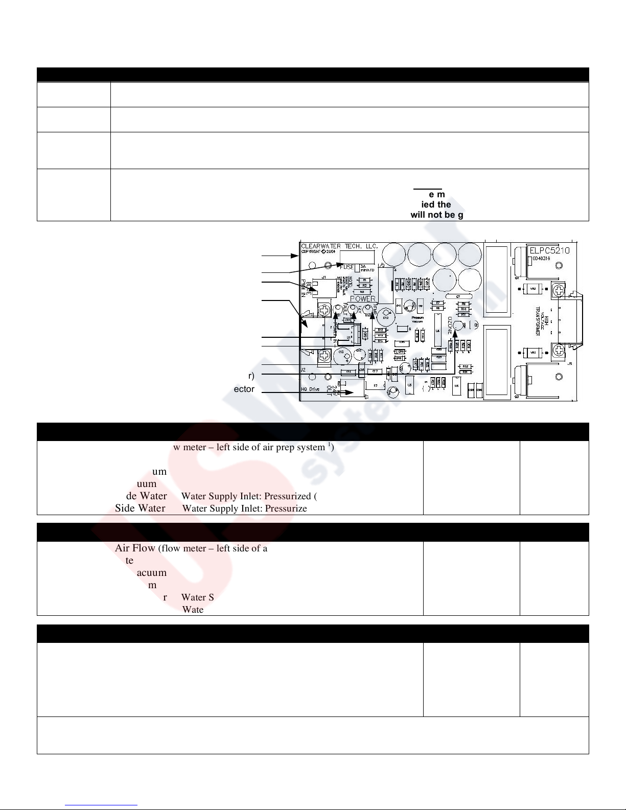
HDO3-II and HDO3-III Drive Board
Figure 7-1 C
Operating Parameters Figure 7-2
HDO3 - I Operating Range Optimum
Air Preparation Air Flow (flow meter – left side of air prep system
1
)
Feed Gas Flow Rate
Ozone Generator - Vacuum
Ozone Injector - Vacuum
High Pressure – Side Water Water Supply Inlet: Pressurized (Non-Pressurized
2
)
Low Pressure – Side Water Water Supply Inlet: Pressurized (Non-Pressurized
2
)
6 to 8 scfh
6 to 8 scfh
-3 to -8 in.Hg.
-5 to -25 in.Hg.
55-65 (35-45) PSI
15-25 (0-5) PSI
8 scfh
8 scfh
-5 in.Hg.
-15 in.Hg.
60 (40) PSI
20 (5) PSI
HDO3 - II Operating Range Optimum
Air Preparation Air Flow (flow meter – left side of air prep system
1
)
Feed Gas Flow Rate
Ozone Generator - Vacuum
Ozone Injector - Vacuum
High Pressure – Side Water Water Supply Inlet: Pressurized (Non-Pressurized
2
)
Low Pressure – Side Water Water Supply Inlet: Pressurized (Non-Pressurized
2
)
10 to 15 scfh
10 to 15 scfh
-3 to -8 in.Hg.
-5 to -25 in.Hg.
55-65 (35-45) PSI
15-25 (0-5) PSI
15 scfh
14 scfh
-5 in.Hg.
-15 in.Hg.
60 (40) PSI
20 (5) PSI
HDO3 - III Operating Range Optimum
Air Preparation Air Flow (flow meter – left side of air prep system
1
)
Feed Gas Flow Rate (Control Panel and Ozone Generator)
Ozone Generator – Pressure (Control Panel and Ozone Generator)
Ozone Injector – Vacuum
High Pressure – Side Water Water Supply Inlet: Pressurized (Non-Pressurized
2
)
Low Pressure – Side Water Water Supply Inlet: Pressurized (Non-Pressurized
2
)
10 to 12 scfh
4 to 6 cfh
9 to 12 PSI
-5 to -25 in.Hg.
55-65 (35-45) PSI
15-25 (0-5) PSI
12 scfh
6 cfh
10 PSI
-15 in.Hg.
60 (40) PSI
20 (5) PSI
1 This flow meter is set at atmospheric pressure. See, “Start-Up and Calibration” steps 8-11. The flow rate will be reduced
when in normal operation.
2 The pressure range is based on possible head pressure and may vary by installation.
Drive Board
Fuse
Variable Input Connector
DC Power Input Connector
Fault LED
Drive Board Main Power LED
Transformer – XFMR LED
Ozone Output LED (illuminates through cover)
24VDC Output Connector
 Loading...