

Clearwater 300-BT Installation Instructions
Series 300-BT Safety Switches
Clearwater Tech - Phone: 800.894.0412 - Fax: 208.368.0415 - Web: www.clrwtr.com - Email: info@clrwtr.com
Installation Instructions
SAFETY
300-BT SERIES
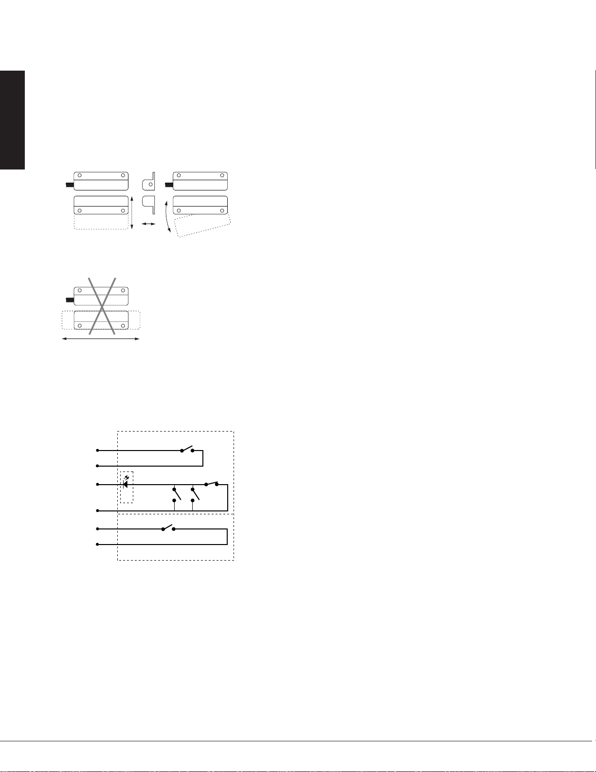
Mounting Configurations
The interlock switch and actuator should be
mounted in only three configurations for actuation:
Figure 1
Figure 2
The parallel actuation can result in on/off/on (double actuation)
signal if the actuator passes by the switch rather than coming to rest
in proximity to it. This is NOT a recommended configuration for
safety interlock applications.
Circuit Configuration
(Optional
Monitoring
Circuit)
Perpendicular
Parallel Actuation
Not Recommended
BLK
CIR.
1
WHT
BLUE
2
CIR.
RED
BRN
CIR.
3
ORG
Actuation
Best Best
Actuation
D1
Door
Optional LED
S2 S3
S5
Pivot
Actuation
Good
Circuits
S1
S4
Installation
1. Position the switch and actuator so the labels are reading in the
same direction.
2. Mount the switch on the stationary frame of the machine and
mount the actuator on the moveable guard, door or gate. Keep the
switch and actuator within the listed sense range.
See Figure 1 and Figure 2 for recommended
mounting configurations.
3. Mounting on a ferrous material will effect the sense range a
minimum of 50%. However, a 1/4" non-ferrous spacer positioned
under the actuator and/or switch should restore most of the lost
sense range.
4. For best protection against operator defeat, mount with nonremovable screws, bolts or nuts (see Accessories).
5. CAUTION: When not used with a INT safety relay particular
care must be taken to determine the actual load of the switch circuit.
High voltage transients from coils, motors, contactors, and
solenoids must be considered. Transient protection, such as
back-to-back zener diodes (TransZorb
recommended for such loads to ensure that maximum ratings of the
switch are not exceeded. Not recommended to be used with
tungsten filament loads because of high current inrush surges. Line
capacitance and load capacitance must be considered. Excessive
line capacitance can be caused by cable lengths over 50' when using
a maximum 48 VAC. A resistor can be added in series to limit the
inrush current (at least 48 Ohms for 24V applications). The resistor
can be added in series just before the load. The voltage drop and
the power rating of the resistor must be considered.
Voltage drop =I•R; Watts = I2R
(I = maximum continuous current of the load).
6. When mounting the switch on an ungrounded machine, ground
the switch housing by connecting your ground lead to one of the
switch mounting screws.
®
) or an RC network, is
*Circuits shown with magnet actuator away from switch.
S1 Normally open reed switch, closed when actuator is within
specified sense range
S2, S3 Normally open reed switches, will close if misaligned or tampered
with a standard magnet
S4 Biased closed reed switch, open when actuatior is between
specified sense range
S5 Normally open reed switch, closed when actuator is within
specified sense range
N.O. circuit: Black and white wires.
N.C. biased tamper circuit: Red and blue wires.
N.O. monitor circuit: Orange and brown wires.
12
GE Interlogix Industrial
1-800-247-9447
Series 300-BT Safety Switches
*300-BLT-
*Or other DPST GuardSwitch
(See the 300-BT Series installation instructions)
(–)
(+)
INT-03-230: 230V AC
INT-03-120: 120V AC
INT-03-024: 24V DC
Required Fast or
Slow-Acting Fuse:
(250V, 5x20 mm F)
INT-03-230: 40mA
INT-03-120: 80mA
INT-03-024: 1/4A
Required Fast or SlowActing Fuses: 4A (250V,
5x20 mm F
W
H
T
B
L
K
R
E
D
B
L
U
*300-BLT-
W
H
T
B
L
K
R
E
D
B
L
U
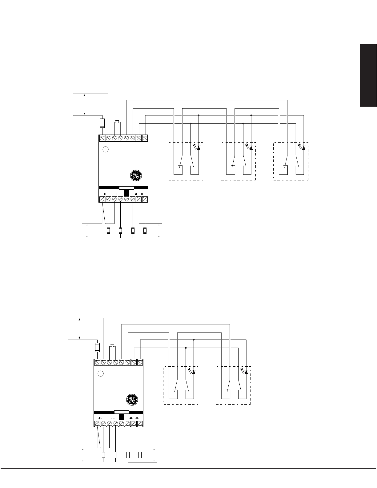
Note – The LED on the BLT model will be ON when the guard is open
Fuses: 1 A (250 v)
Multiple DPST GuardSwitches – Shown with actuators in position, all guards closed.
The L.E.D of the BLT model will be on when the guard is open. If multiple guards
are open, L.E.D will be dimmer. The maximum number of GuardSwitches that can
be used is 50, although troubleshooting and line resistance must be considered.
(Do not exceed 30 Ohms of combined contact and line resistance. Each GuardSwitch
will have less than 0.5 Ohms of resistance.)
RESET
A
SAFE AUX.
BCD
Safety Monitor Relay
INT-03
EFG
OUTPUTS
230 VAC
60 VDC
120 VAC
30 VDC
LOADS
*300-BLT-
W
H
T
B
L
K
R
E
D
B
L
U
Series Circuit
Parallel Circuit
–
+
L1 L2 1 2 X1 X2 Y1 Y2
N.O. N.C.
Clearwater Tech - Phone: 800.894.0412 - Fax: 208.368.0415 - Web: www.clrwtr.com - Email: info@clrwtr.com
Installation Instructions
Wiring Diagram For Category 3
Inputs shown with safety gates/guards in closed position.
When guards are closed, safe outputs are closed.
One 300-BT Series GuardSwitch required for each safety gate, one INT relay for each machine.
300-BT SERIES
SAFETY
Wiring Diagram For Category 4
Inputs shown with safety gates/guards in closed position.
When guards are closed, safe outputs are closed.
Two 300-BT Series GuardSwitches with one INT relay are required for each safety gate.
When first applying the GuardSwitch Monitor Relay, the inputs must be cycled to check for proper operation
before the output contact close. To cycle the inputs, the guard must be opened and then closed. This start-up
test is sufficient; however, we recommend that the proper operation of the switches and relay be checked at
least every 24 hours.
(–)
INT-03-230: 230V AC
Required Fast or
Slow-Acting Fuse:
(250V, 5x20 mm F)
INT-03-230: 40mA
INT-03-120: 80mA
INT-03-024: 1/4A
1-800-247-9447
INT-03-120: 120V AC
INT-03-024: 24V DC
(+)
Required Fast or
Slow-Acting
Fuses: 4A (250V,
5x20 mm F
230 VAC
60 VDC
RESET
L1 L2 1 2 X1 X2 Y1 Y2
–
+
Safety Monitor Relay
INT-03
SAFE AUX.
A
BCD
LOADS
OUTPUTS
N.O. N.C.
R
W
H
T
EFG
*Or other DPST GuardSwitch
120 VAC
30 VDC
(See the 300-BT Series
installation instructions)
B
B
E
L
L
D
U
K
*300-BLT-
Note – The LED on the BLT model
will be ON when the guard is open
Fuses: 1A (250V)
W
H
T
R
B
E
L
D
K
*300-BLT-
B
L
U
GE Interlogix Industrial
13
 Loading...