


Pentz EF5 Installation Guide
Clear Vue
Cyclones
145 Nix Road
Liberty, SC 29657
888-299-0221
www.clearvuecyclones.com

Disclaimers & Warning s
WARNING: All persons, by purchasing a motorized dust collection syst em, motor, or
individual parts from CLEAR VUE CYCLONES, or using these instructions which are
provided as suggestions only, agree to the following disclaimer:
Installing and/or operating this motorized dust collection system, or use of individual
parts, involves the risk of serious bodily injury or even death. The buyer and user
accept total responsibility for any and all operation or use that may lead to personal
injury, economic loss, social distress, other losses, costs and damages. Seller is not
responsible for injuries and or damages of any kind resulting from operating this
motorized dust collection system, motor, or use of individual parts or instructions.
All Rights Reserved, October 2018
Duplication of any part of this manual without expressed written permission from
Bushey Enterprises, Inc. is prohibited.
IMPORTANT!
Minimum Recommended Ceiling Height
A minimum floor-to-ceiling height of 113 inches is required for systems with a 30-gallon
drum. Systems with a 55-gallon drum require a minimum floor-to-ceiling height of 119
inches. The content of this manual is based upon the assembly of the system with the
necessary ceiling height.
Leaks
To maximize performance of your dust collection system, it will be imperative to check for
leaks. Leaks on the suction side of the system will reduce the CFM (cubic feet per minute)
performance levels. We recommend the sealing of all connections in your ducting.
Leaks in the collection drum or at the bottom of the cyclone are a major problem. Such leaks
will cause an up-flow of air through the cyclone and prevent the dust from entering the
collection drum. This will affect the separation efficiency of the cyclone and m or e dus t will
advance through to your filters, which may cause blockage.
Leaks found anywhere after the dust reaches the blower may be blown back into your shop.
This is a hazardous situation and these leaks should be sealed immediately.
Testing for leaks can be done by performing a “smoke test”. With any smoke-producing
device (such as an incense stick), waft the smoke around the various seams of the system.
Leaks in the ducting will cause the smoke to disperse. Leaks around the base of the cyclone
will cause the smoke to be pulled in. Seal any leaks for optimal performance.
1 Pentz EF5 Installation Guide
© Clear Vue Cyclones 2018

Table of Contents
Disclaimers & Warnings ..................................................................................... 1
Table of Contents ............................................................................................... 2
Dimensional Drawing ......................................................................................... 3
Cyclone Components ......................................................................................... 4
Specifications ..................................................................................................... 5
Installation Tools ................................................................................................ 6
Shipment Contents ............................................................................................. 7
Mounting the Backer Board and Wall Bracket (for wall-mounted systems only) ....... 8
Assembling the Metal Stand (for stand-mounted systems only) ................................ 9
Constructing the Motor Assembly .................................................................... 10
Attaching the Impeller ...................................................................................... 11
Assembling and Hanging the Cyclone ............................................................. 12
Assembling the Flangeless Filter Stack (filtered systems only) ....................... 13
Installing the Exhaust and Collection Drum ...................................................... 14
Electrical – Single-Phase Motors ..................................................................... 15
Electrical – Three-Phase Motors ...................................................................... 16
2 Pentz EF5 Installation Guide
© Clear Vue Cyclones 2018
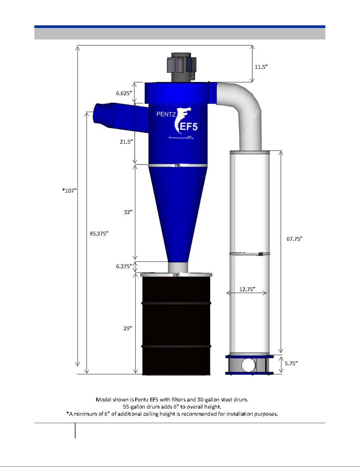
Dimensional Drawing
3 Pentz EF5 Installation Guide
© Clear Vue Cyclones 2018

Cyclone Components
4 Pentz EF5 Installation Guide
© Clear Vue Cyclones 2018

Specifications
6” Intake
8” Intake
1,701 CFM at baseline static pressure
of 2.25”
1,935 CFM at baseline static pressure
of 2.25”
Footprint with Filters*
52” x 21-½”
52” x 21-½”
Footprint without
Filters*
Minimum Height**
107”
107”
Single Phase – 234 lbs
Three Phase – 284 lbs
Single Phase – 234 lbs
Three Phase – 284 lbs
Single Phase – 190 lbs
Three Phase – 240 lbs
Single Phase – 190 lbs
Three Phase – 240 lbs
16 ga rolled black metal steel, powder
coated
16 ga rolled black metal steel, powder
coated
Blower Assembly
16” steel, backward-inclined impeller
16” steel, backward-inclined impeller
Cyclone Diameter
18”
18”
6” ID w/QF rolled edge (sized for
Nordfab ducting) – adapters available
8” ID w/QF rolled edge (sized for
Nordfab ducting) – adapters available
Intake Angle
Upward, 9°
Upward, 9°
Country of Origin
USA
USA
Assembly Time
2 hours, with 2 people
2 hours, with 2 people
Motor:
Manufacturer
Leeson Motor Company
Leeson Motor Company
HP Rating
5 HP, non-TEFC
5 HP, non-TEFC
Speed
3,450 rpm
3,450 rpm
Single Phase – 20.8 FLA at 230V
6.1 FLA at 460V
Single Phase – 20.8 FLA at 230V
6.1 FLA at 460V
Manual Overload
Protection
Electrical:
Single Phase – 30 amps
10 amps at 460V
Single Phase – 30 amps
10 amps at 460V
Min. Recommended
Wire Size
Remote
RF
RF
Remote Range
60’
60’
Filters:
Manufacturer
Wynn Environmental
Wynn Environmental
Model #
9B300NANO
9B300NANO
Material
100% Nanofiber laminate
100% Nanofiber laminate
Area
300 sq ft each
300 sq ft each
Separation Efficiency
99.999% at 0.5 micron
99.999% at 0.5 micron
MERV Rating
15
15
Dimensions
12.75” OD x 34” H x 8.4” ID
12.75” OD x 34” H x 8.4” ID
System Performance
Weight with Filters
Weight without Filters
Cyclone Construction
Intake Size
45” x 21-½” 45” x 21-½”
Current
Minimum Circuit Size
* Dimensions based on intake positioned 180° from exhaust. Depth/width will vary depending on rotation.
** Height with 30-gallon drum. Add 6” for 55-gallon drum. A minimum of 6” of additional height is recommended for installation
purposes.
Three Phase – 12.2 FLA at 230V
Yes Yes
Three Phase – 15 amps at 230V
10 gauge 10 gauge
Three Phase – 12.2 FLA at 230V
Three Phase – 15 amps at 230V
5 Pentz EF5 Installation Guide
© Clear Vue Cyclones 2018

Installation Tools
9
•
∕
” Wrench
16
7
•
∕
” Wrench
16
• ¾” Wrench
3
•
∕
” Hex Key
32
• Drill
• Level
• Hammer
• 6’ Ladder
• Tape Measure
• Box Cutter
• (1) tube of Caulk
o ALEX PLUS Acrylic Latex Caulk plus Silico ne (color Crystal Clear) is
recommended simply because it dries the clearest. Other brands/types may
be used.
6 Pentz EF5 Installation Guide
© Clear Vue Cyclones 2018

Shipment Contents
• Leeson Motor – single phase or three phase
• 16” Impeller with taper lock bushing
• 16” Blower Housing with Motor Plate
• ¼” Neoprene Gasket
• Upper Cylinder
• Cone
• Intake Transition – 6” or 8” (will be mounted to intake on Upper Cylinder)
• 18” Clamp
• 6” Flex Hose – 6” length
• (2) 6” flex hose clamps
• Steel Drum with Lid & Collar – 30-gallon or 55-gallon
• Wall Bracket (for wall-mounted systems only)
• Backer Board (for wall-mounted systems only)
• Metal Stand (for stand-mounted systems only:
o (1) Upper frame
o (4) Upper legs
o (1) Center frame
o (4) Lower legs
• 8” Flex Hose – 5’ length
• (2) 8” Flex Hose Clamps
• (2) NANO Cartridge Filters – filtered systems only
• Filter Flange with Collar – filtered systems only
• Filter Clamp with Hardware – filtered systems only
o (1) band clamp
o (1) ¼”-20 x 1” bolt
o (1) ¼”-20 flat washer
o (1) ¼”-20 wing nut
• Filter Clean Out Box – filtered systems only
• Electrical Box with Remote – single phase systems only
• Hardware Kit:
Single Phase Hardware Kit Three Phase Hardware Kit
o (12) ¼"-20 x 1" Hex Bolts
o (14) ¼" Split Lock Washers
o (16) ¼" Flat Washers
o (4)
o (4)
o (4)
o (4) #6 x 1-¼" Sheet Rock Screws
o (6)
o (10)
o (4)
o (4) ¼"-20 x 2" Hex Bolts
o (2) ¼"-20 Nuts
3
/8"-16 x ¾" Hex Bolts
3
/8" Flat Washers
3
/8" Lock Washers
5
/16"-9 x 3" Hex Head Lag Screws
5
/16" Flat Washers
5
/16"-9 x 4" Hex Head Lag Screws
o (12) ¼"-20 x 1" Hex Bolts
o (14) ¼" Split Lock Washers
o (16) ¼" Flat Washers
o (4) ½"-13 x 1" Hex Bolts
o (4) ½" Flat Washers
o (4) ½" Lock Washers
o (4) #6 x 1-¼" Sheet Rock Screws
o (6)
o (10)
o (4)
o (4) ¼"-20 x 2" Hex Bolts
o (2) ¼"-20 Nuts
5
/16"-9 x 3" Hex Head Lag Screws
5
/16" Flat Washer
5
/16"-9 x 4" Hex Head Lag Screws
Check the contents of your shipment as soon as possible to verify there
was no damage sustained during transit. If there are any issues, please
contact Customer Service at 888-299-0221.
7 Pentz EF5 Installation Guide
© Clear Vue Cyclones 2018
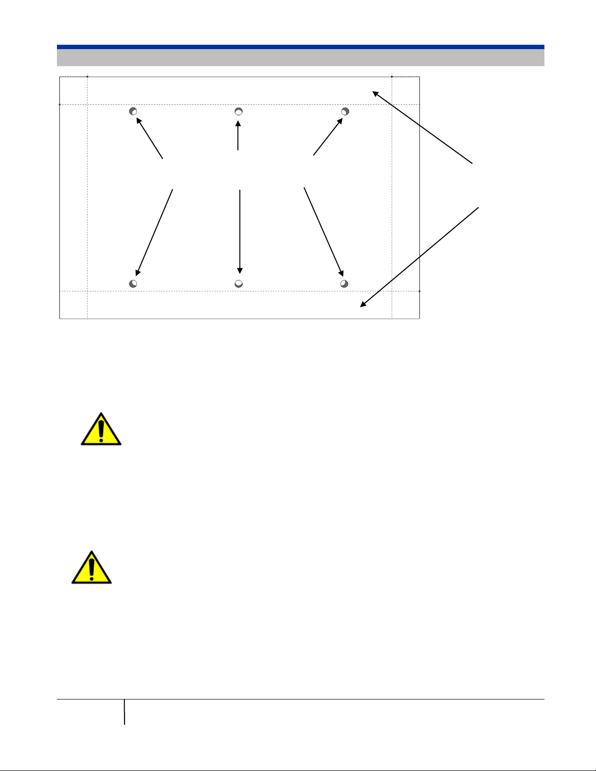
Holes used for mounting Wall
Space used for
Mounting the Backer Board and Wall Bracket (for wall-mounted systems only)
Bracket to Backer Board
1. Determine the location of the Backer Board on your wall:
a. Position the Backer Board so that at least one set of vertical holes are centered over
a stud.
b. The top of the Backer Board must be mounted at a minimum height of 73” above
your floor for a 30-gallon drum and 79” above the floor for a 55-gallon drum.
c. Use a level to verify that the Backer Board is level.
mounting
Backer Board to
wall
The Backer Board can be mounted higher if desired – a longer length of flex
hose can be used between the base of the cyclone and collection drum to take
up any excess height.
2. Secure the Backer Board to your wall using (4) 5/16"-9 x 4" lag screws and (4) 5/16" flat washers.
a. Position the screws no more than 2” from the outer edges of the Backer Board to
allow enough clearance to mount the Wall Bracket.
b. Locate at least (2) of the screws into a stud.
c. Use a level to verify that the Backer Board is level.
If the holes in the Wall Mounting Bracket can be secured into at least (2) studs,
use of the Backer Board is optional. If not used, the top of the Wall Mounting
Bracket must be mounted at a minimum height of 71” above your floor for a 30gallon drum and 77” above the floor for a 55-gallon drum. Use a level to verify
that the Wall Mounting Bracket is level.
3. Attach the Wall Bracket to the Backer Board:
a. Center the Wall Bracket so that the (6) holes on the Bracket are aligned with the
holes on the Backer Board.
b. Secure the Wall Bracket using (6)
5
/
"-9 x 3" lag screws and (6)
16
5
/
" flat washers.
16
c. If desir ed, the holes may be pre-drilled in advance.
8 Pentz EF5 Installation Guide
© Clear Vue Cyclones 2018

Upper Frame
Upper Legs
Center Frame
Lower Legs
Assembling the Metal Stand (for stand-mounted systems only)
1. Place the center fr ame f or the st and on the floor.
2. Slide the (4) lower legs onto the ce nter frame and
tighten the set screws.
3. Flip the stand over so the
lower legs are facing down.
4. Slide the (4) upper legs onto the center frame.
5. Slide the upper frame onto the upper legs.
6. Adjust the set screws to ensure stand is level.
It is recommended to bolt the stand to the floor to ensure it
does not move.
9 Pentz EF5 Installation Guide
© Clear Vue Cyclones 2018
Constructing the Motor Assembly
1. Locate the motor plate – it is the round disc secured to the top of the Blower Housing.
a. Remove the bolts and washers using a
9
∕
” wrench and set hardware aside.
16
2. Stand the motor on end, with the shaft facing up towards the ceiling.
3. Install (1)
face of the motor, using (1)
3
/8"-16 x ¾" hex bolt through each of the holes on the motor plate, into the holes on the
3
∕
” lock washer and (1)
8
3
∕
” flat washer per bolt.
8
For three phase motors, substitute with ½"-13 x 1" hex bolts, ½" lock washers and ½" flat
washers.
4. Tighten each motor bolt securely.
Do NOT turn the motor on until the system is completely
assembled, including the collection drum. Doing so may cause
the circuit breaker to trip, physical damage to the system and/or
bodily harm.
10 Pentz EF5 Installation Guide
© Clear Vue Cyclones 2018

≥¼”
1
∕
8
” –
1
∕
4
”
This end UP
Attaching the Impeller
Improper installation of your impeller can lead to the impeller coming off during
operation. Significant damage to your system and/or bodily harm can result. It
is imperative that you read and follow these directions closely. Detailed
assembly videos can be found under the Education Center/Assembly
Instruction section of our website at www.clearvuecyclones.com.
1. Locate the taper-lock bushing (and screws) installed on the imp eller.
a. Remove it by inserting the (3) taper-lock bolts into the smaller, threaded holes in the
bushing and tightening them down until taper-lock releases from the impeller hub.
b. Pry the taper-lock slightly open by inserting a flat-head screwdriver into t he s lit in the side.
2. Loosely reattach the t aper-lock bushing to the impeller:
a. Insert the (3) taper-lock bolts into the larger, non-threaded holes in
the taper-lock bushing.
b. Slide the taper-lock into the hub in the center of the impeller with the
wider side up, lining up the taper-lock bolts with the threaded holes
on the impeller.
c. Finger-tighten the bolts to secure them in place.
Make sure the taper-lock bolts are inserted through the larger,
non-threaded holes in the taper-lock bushing, into the threaded
holes of the impeller. The alternate set of holes is used for
impeller removal only.
3. Position the impeller:
a. Slide the impeller onto the motor shaft, with the taper-lock bushing facing up.
b. Insert the motor key and lightly tighten the setscrew using a
3
∕
” hex key until it cannot fall
32
out.
c. For single phase motors, lift the impeller so that the taper-lock is flush with the top of the
motor shaft.
d. For three phase motors, lift the impeller so that the taper-lock sits ¼” below the top of the
motor shaft.
4. Tighten the taper-lock bolts:
a. Consecutively tighten each taper-lock bolt by a ¼
revolution, until t hey are all ti ght.
The tightening of each bolt wi ll cause the subsequent
bolts to feel as if they’ve loos ened.
b. Repeat this process until each bolt is torq ued to the
manufacturer’s specificat ion of 5 ft/lb s.
Upon completion, there s hould be a minimum of ¼”
clearance betwee n the back of the imp eller and the
motor bolts intalled in the motor plate. T here also may
1
1
∕
” –
∕
be up t o a
” gap between the taper-lock
8
4
bushing and the impeller hub.
5. Firmly tighten the set screw aga inst the motor key us ing a
11 Pentz EF5 Installation Guide
© Clear Vue Cyclones 2018
3
∕
” hex key.
32

Assembling and Hanging the Cyclone
1. Locate the Blower Housing and Upper Cylinder.
a. Determine the desired orientation of the cyclone intake on the Upper Cylinder
relative to the exhaust opening on the Blower Housing.
The position of the intake can be rotated in one of (12) different configurations with respect
to the exhaust. This will not affect system performance in any way.
2. Secure the Blower Housing to the Upper Cylinder:
a. Place the ¼” neoprene gasket on top of the Upper Cylinder, lining up the holes in
the gasket with the holes on the top of the Upper Cylinder.
b. Position the Blower Housing, with the exhaust in the desired orientation with respect
to the intake, lining up the holes on the bottom of the Blower Housing with the holes
on the top of the Upper Cylinder.
c. Using a 7/16” wrench, secure the Blower Housing to the Upper Cylinder using (1) ¼"-
20 x 1" hex bolt, (1) ¼” lock washer and (1) flat washer per hole.
d. Repeat for all holes and tighten securely.
3. For wall-mounted systems, with the assistance of a helper, lift the Upper Cylinder assembly up
and slide it back so that the lip is resting on the horizontal arms of the Wall Mounting Bracket.
a. For stand-mounted systems, lift the Upper Cylinder assembly up and lower it
through the top opening of the stand so that the lip is resting on upper frame of the
stand.
4. Attach the Cone to the bottom of the Upper Cylinder using the 18” cl amp.
5. Install the motor/impeller assembly:
a. With the help of your installation partner, turn the motor/impeller assembly over so that
the fins of the impeller are facing downward.
If your system came with an Electrical Box, it is recommended that you wi re the 6’ whip into
the wiring box of the motor first, prior to installing the motor/impeller assembly. Please refer
to the Electrical Box instruction sheet for more detail.
b. With the help your installation partner, lift the motor/impeller assembly up and lower
the impeller down inside the Blower Housing. Rotate the assembly so that the
holes on motor plate line up with the holes on the Blower Housing top.
Systems using a 30-gallon drum require a minimum of 113” of ceiling
height in order to have adequate clearance above the Blower Housing
for installing the motor/impeller assembly. Systems using a 55-gallon
drum require a minimum of 119” of ceiling height.
c. Secure the motor plate to the Blower Housing using (1) 3/8"-16 x 3/4" hex bolt, 3/8" lock
washer and 3/8" flat washer per hole.
d. Tighten securely.
Do NOT turn the motor on until the system is completely assembled,
including the collection drum. Doing so may cause the circuit breaker
to trip, physical damage to the system and/or bodily harm.
12 Pentz EF5 Installation Guide
© Clear Vue Cyclones 2018

Assembling the Flangeless Filter Stack (filtered systems only)
1. Stack the two filters together, one on top of the other.
2. Run a bead of silicone caulk around the outside of the seam where the two filters meet .
3. Secure the band clamp:
a. Place a ¼”-20 flat washer on the ¼”-20 x 1”
bolt.
b. Wrap the band clamp around the seam
between the two filters.
c. Insert the ¼”-20 x 1” bolt with the ¼”-20 flat
washer through the hole on the band clamp
and tighten.
d. Place a ¼”-20 wing nut on the hex bolt and
tighten.
4. Place the stacked filters on top of the Filter Clean
Out Box.
a. Run a bead of clear silicone caulk around the base of the filters, where they meet the
Filter Clean Out Box, to ensure an airtight seal. The silicone caulk will hold the filters
securely in place and can be removed easily by cutting the bead with a razor knife.
b. Run a bead of clear silicone caulk around the seams where the PETG wrapper meets
the MDF top and bottom on the Filter Clean Out Box.
5. Mount the Filter Flange to the top of the Filter Stack.
a. Run a bead of silicone around the top of the filter stack.
b. Secure the Filter Flange to the top of the filters using (4) #6 x 1-¼" sheet rock screws.
13 Pentz EF5 Installation Guide
© Clear Vue Cyclones 2018

Installing the Exhaust and Collection Drum
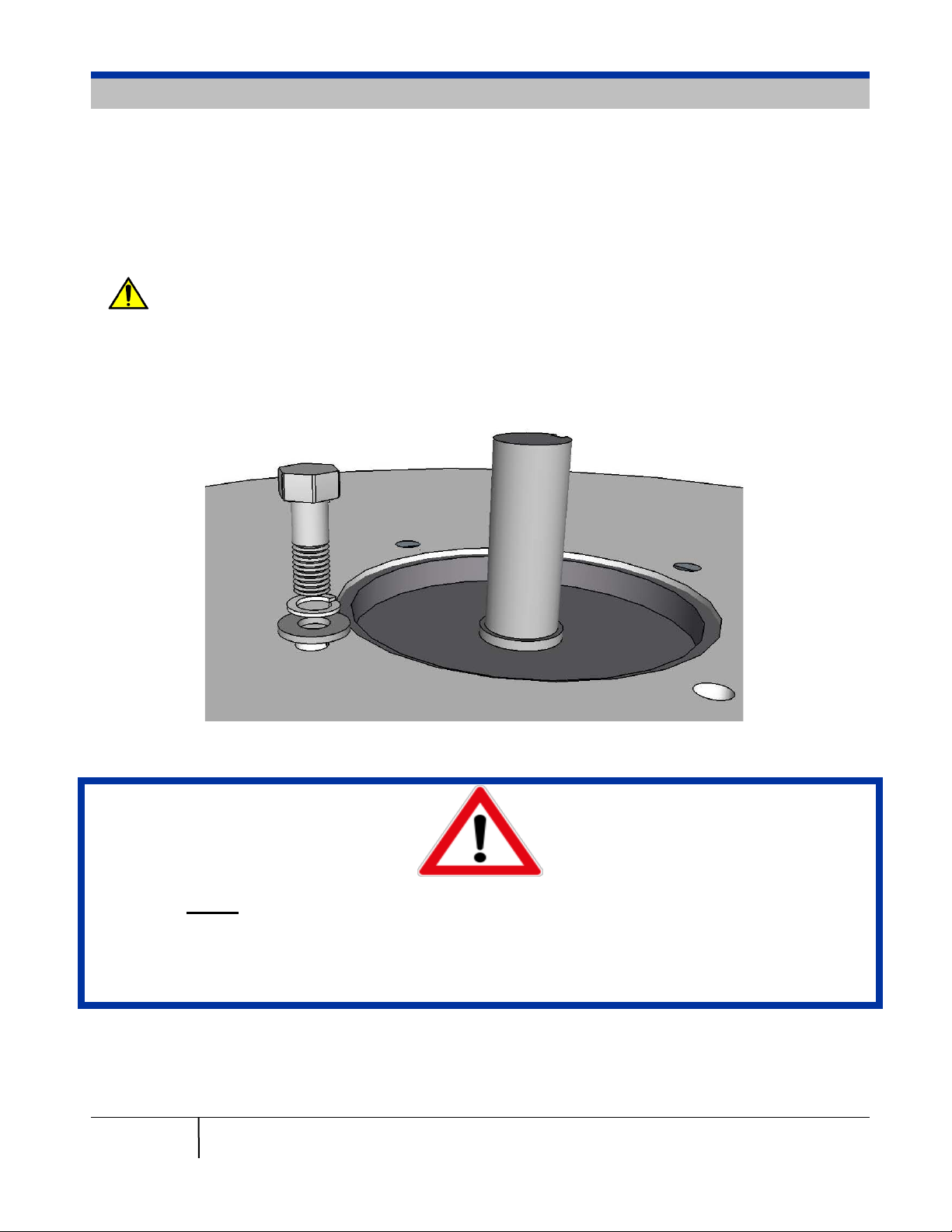
1. Attach the 8” Flex Hose to the Blower Housing Exhaust.
a. Secure the hose to the collar with an 8” flex hose clamp.
b. Caulk the hose to seal it in place.
2. Secure the end of the Exhuast Hose:
a. Place an 8” flex hose clamp over the top of the flex hose. Make sure it is loose.
b. If using filters, secure the hose to the filter flange mounted on top of th e filte r stack .
c. If venting outside, secure the the hose to your exhause vent.
d. Tighten the flex hose clamp and caulk the hose to secure it in place.
2. Attach the short length of 6” flex hose provided to the collar on the collection drum lid:
a. Secure the hose to the collar with a 6” flex hose clamp.
b. Caulk the hose from both sides of the lid to seal it in place.
3. Attach the lid to the cyclone:
a. Place a 6” flex hose clamp over the top of the flex hose. Make sure it is loose.
b. Install the lid by placing the 6” flex hose over the base of the cyclone.
The flex hose will be an extremely tight fit around the base of the cyclone. This is by design
in order to make sure the connection is air tight. The flex hose can be made more pliable
for installation by heating it with a hair dryer.
c. Tighten 6” flex hose clamp to secure flex hose to the base of the cyclone.
d. Run a bead of clear silicone caulk around the seam at the top of the flex hose.
A longer length of flex hose may be used between the base of the cyclone and collection
drum lid, if needed.
Final Adjustments
1. For both wall-mounted and stand-mounted systems, once assemly is complete, it is
recommended to bolt the cyclone in place.
a. Predrill (2) holes – one on each side – of the ring on the Upper Cylinder in a location
where the ring makes contact with either the horizontal member of the Wall Brac ket or
the frame of the s tand.
b. Extend the holes down through the Wall Bracke t or frame .
c. Secure the Upper Cylinder to the Wall Bracket/frame using (1) ¼"-20 x 2" bolt, (2) ¼"-
20 flat washers, (1) ¼"-20 lock washer and (1) ¼"-20 nut through each hole.
2. For stand-mounted systems, it is recommended to additonally bolt the stand to the floor to
ensure it does not move.
14 Pentz EF5 Installation Guide
© Clear Vue Cyclones 2018
Electrical – Single-Phase Motors
Clear Vue Cyclones highly recommends the use of a professional,
licensed electrician to complete the wiring and any electrical work
associated with this installation. Significant damage to your system and/or
bodily harm can result.
The Leeson 5HP motor is designed to rotate either clockwise or counter-clockwise. Motors
are prewired direct from Leeson and may be wired for either rotation. You will need to
check the wiring to ensure it is correct.
Please also refer to the assembly sheet provided with the Electrical Box.
1. Follow the directions on the Leeson motor for wiring the motor for a clockwise rotation:
a. Connect L1 to P1.
b. Connect L2 to both T4 & T8.
c. Connect P3 & T1 & T5 – wire together and cap off with a wire lug.
d. Connect the ground wire (bare wire) to the green screw inside the motor connection
box.
Leeson recommends the use of wire lugs in lieu of wire nuts to secure all connections.
Leeson defines motor rotation with the motor shaft facing away. For our installation
puposes, rotation is defined from the opposite end of the motor. In order to obtain a
counter-clockwise rotation when veiwed from below, please follow the clockwise
instructions on Leeson’s motor plate, which match step 1 above.
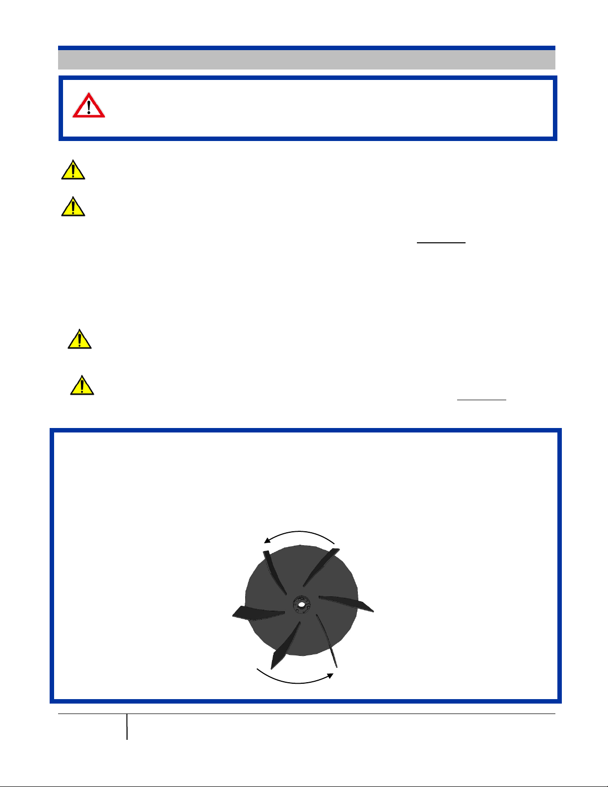
Once the motor is wired, it is important to verify the rotation of the impeller. Disconnect the
flex hose attached to the Blower Housing exhasut to check rotation. From this vantage point,
the impeller should be rotating from the back of the Blower Housing towards the front.
Note that our impellers are backward inclined, allowing our system to move high volumes of
air at a variety of static pressures. Each blade on the impeller has a slight “C” shape. When
rotating correctly, the convex side of the blade will be hitting the air first.
15 Pentz EF5 Installation Guide
© Clear Vue Cyclones 2018
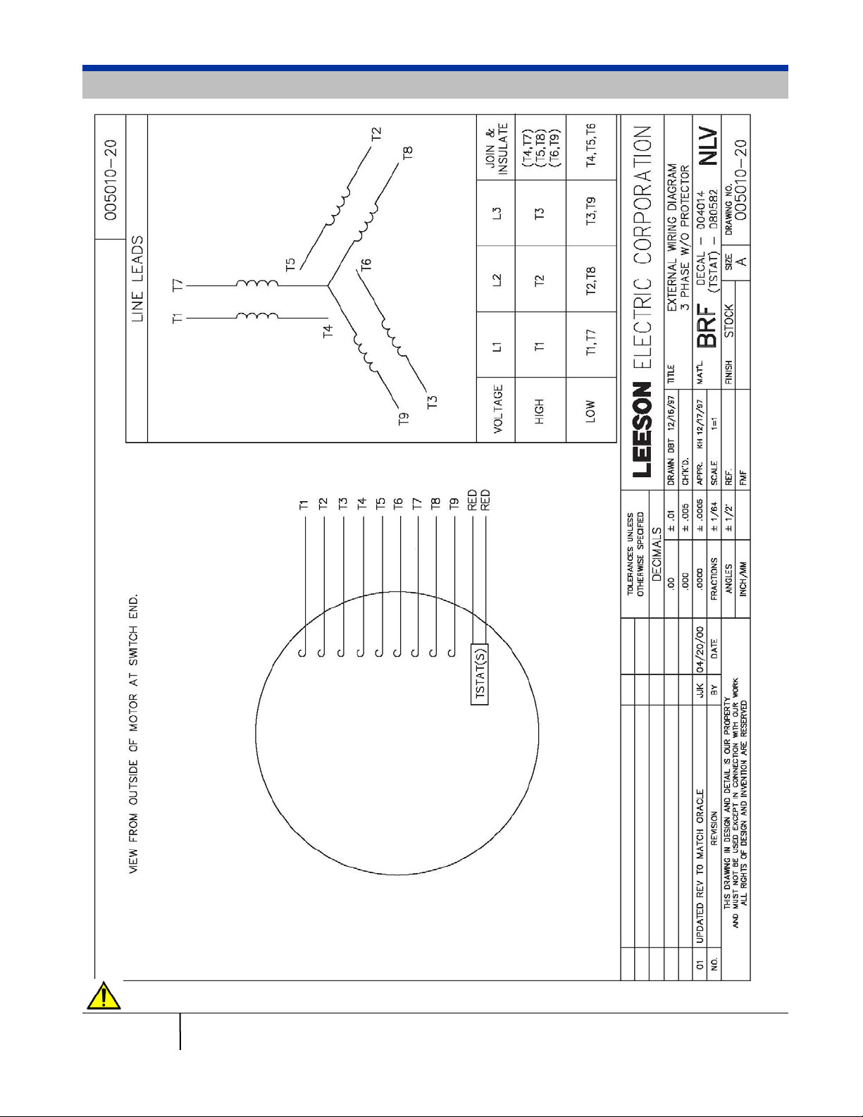
Electrical – Three-Phase Motors
Leeson recommends the use of wire lugs in lieu of wi re nuts to secure all connections.
16 Pentz EF5 Installation Guide
© Clear Vue Cyclones 2018
 Loading...