

Page 1

Network Video Recorder
Quick Start Guide
Version 1.5.0
Page 2

i
Table of Contents
1 Hardware Installation and Connection .......................................................................... 1
1.1 Check Unpacked NVR .......................................................................................... 1
1.2 About Front Panel and Rear Panel ..................................................................... 1
1.3 After Remove the Chassis .................................................................................... 1
1.4 HDD Installation ..................................................................................................... 1
1.5 Front Panel ............................................................................................................. 3
1.6 Rear Panel .............................................................................................................. 4
2 GUI Operation ................................................................................................................... 8
2.1 Boot up .................................................................................................................... 8
2.2 Login ........................................................................................................................ 8
2.3 Smart Add ............................................................................................................... 9
2.4 Remote Device ..................................................................................................... 10
2.5 Schedule ............................................................................................................... 12
2.6 Realtime Playback ............................................................................................... 14
3 Web Operation ................................................................................................................ 16
3.1 Network Connection ............................................................................................ 16
3.2 Login ...................................................................................................................... 17
3.3 Main Window ........................................................................................................ 17
Page 3

ii
Welcome
Thank you for purchasing our network video recorder!
This quick start guide is designed to b e a r eference tool for your system.
Please open the accessory bag to check the items one by one in accor dance with the list below.
Contact your local retailer ASAP if something is missing or damaged in the bag.
Page 4

iii
Important Safeguards and Warnings
1.Electrical safety
All installation and operati on her e s hould conform to your local electrical safety codes.
The product must be grounded t o r educe the risk of electric shock.
We assume no liability or responsibility for all the fires or electrical shock caused by improper
handling or installation.
2.Transportation security
Heavy stress, violent vibration or water splash are not allowed during transportation, storage and
installation.
3.Installation
Keep upwards. Handle with car e.
Do not apply power to the NVR befor e completing installation.
Do not place objects on the NVR.
4.Qualified engineers needed
All the examination and repair w ork should be done by the qualified service engineers.
We are not liable for any problems cau sed by unauthorized modificat io ns or attempted repair.
5.Environment
The NVR should be installed in a c ool, dr y place away from direct sunlight, inflammable,
explosive substances and etc.
This series product shall be transported, storage and used in the specified environments.
6. Accessories
Be sure to use all the accessories recommended by manufacturer.
Before installation, please open the package and chec k all the components are included.
Contact your local retailer AS AP if something is broken in your package.
7. Lithium battery
Improper battery use may r es ult i n fire, explosion, or personal inj ur y!
When replace the battery, pleas e make sure you are using the same m odel!
CAUTION
RISK OF EXPLOSION IF BATTERY IS REPLACED BY AN INCORRECT TYPE.
DISPOSE OF USED BATTERIES ACCORDING TO T HE INSTRUCTIONS.
Before your operation please read the following instructions carefully.
Installation environment
Keep away from extreme hot places and sources;
Avoid direct sunlight;
Keep away from extreme humid places;
Avoid violent vibration;
Do not put other devices on the top of the NVR;
Page 5

iv
Be installed in well ventilat ed place; do not block the vent.
Accessories
Check the accessories aft er opening the box:
Please refer to the packi ng list in the box *
Page 6
1
1 Hardware Installation and Connection
Note: All the installation and operations here should conform to your local electric
safety rules.
1.1 Check Unpacked NVR
When you receive the NVR from the forwarding agent, please check whether there is any visible damage.
The protective materials us ed f or t he package of the NVR can protect most ac cide ntal clashes during
transportation. Then y ou can open the box to check the accessor ies.
Please check the items in accord ance with the list (Remote contro l is optional). Finally you can re mov e the
protective film of the NVR.
1.2 About Front Panel and Rear Panel
For detailed information of the function keys in the front panel and the ports in the rear panel, please refer
to the User’s Manual included in the resource CD.
The model number in the stic k on the bottom of NVR is very important ; please check according to y our
purchase order.
The label in the rear panel is very important too. Usually w e need you to represent the serial number when
we provide the service after sales.
1.3 After Remove the Chassis
Please check the data cable, power cable, COM cable and main bo ar cable connection is secure or not.
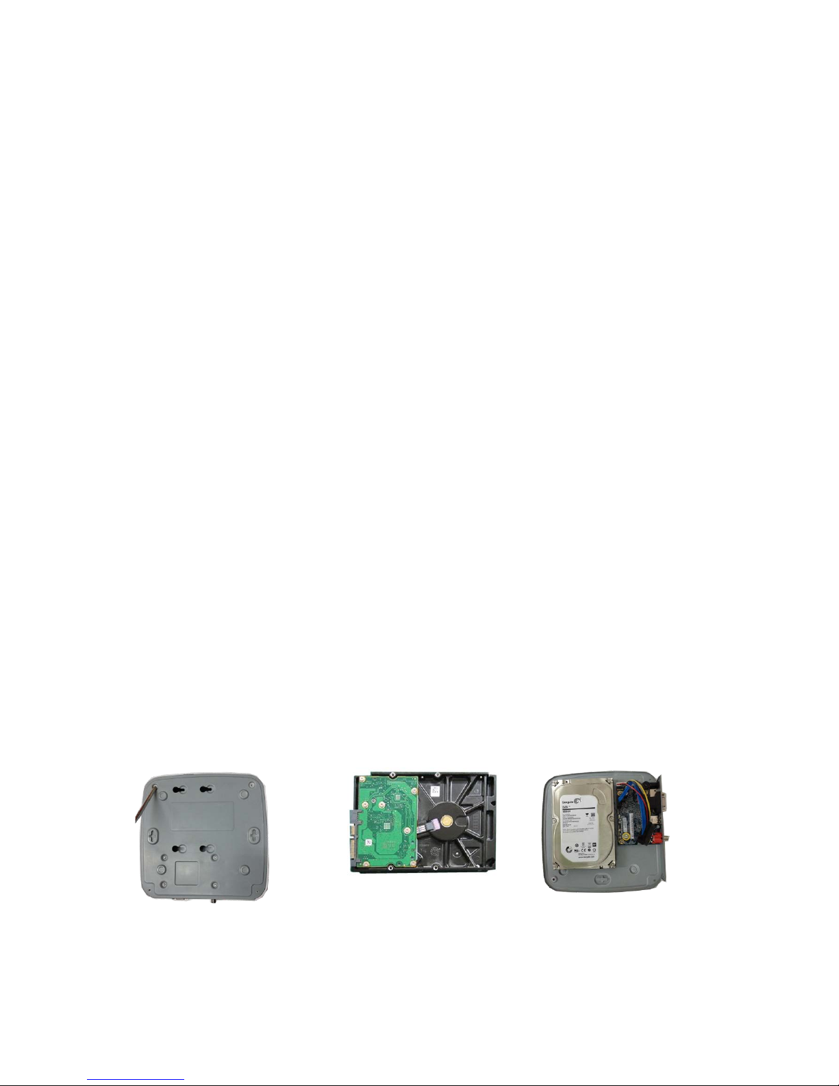
1.4 HDD Installation
Important:
Please turn off the power before you replace the HDD.
The pictures listed below for reference only
You can refer to the User’s Manua l for recommended HDD brand. Please use HDD of 7200rpm or higher.
Usually we do not recommend t he PC HDD.
1.4.1 WiFI-NVR-4 Series
○
1
E A. Loosen the screws of the upper
cover and side panel.
A
○
2
E A Fix four screws in the HDD
(Turn just three rounds).
A
○
3
E A Place the HDD in
accordance with the four holes
in the bottom.
Page 7
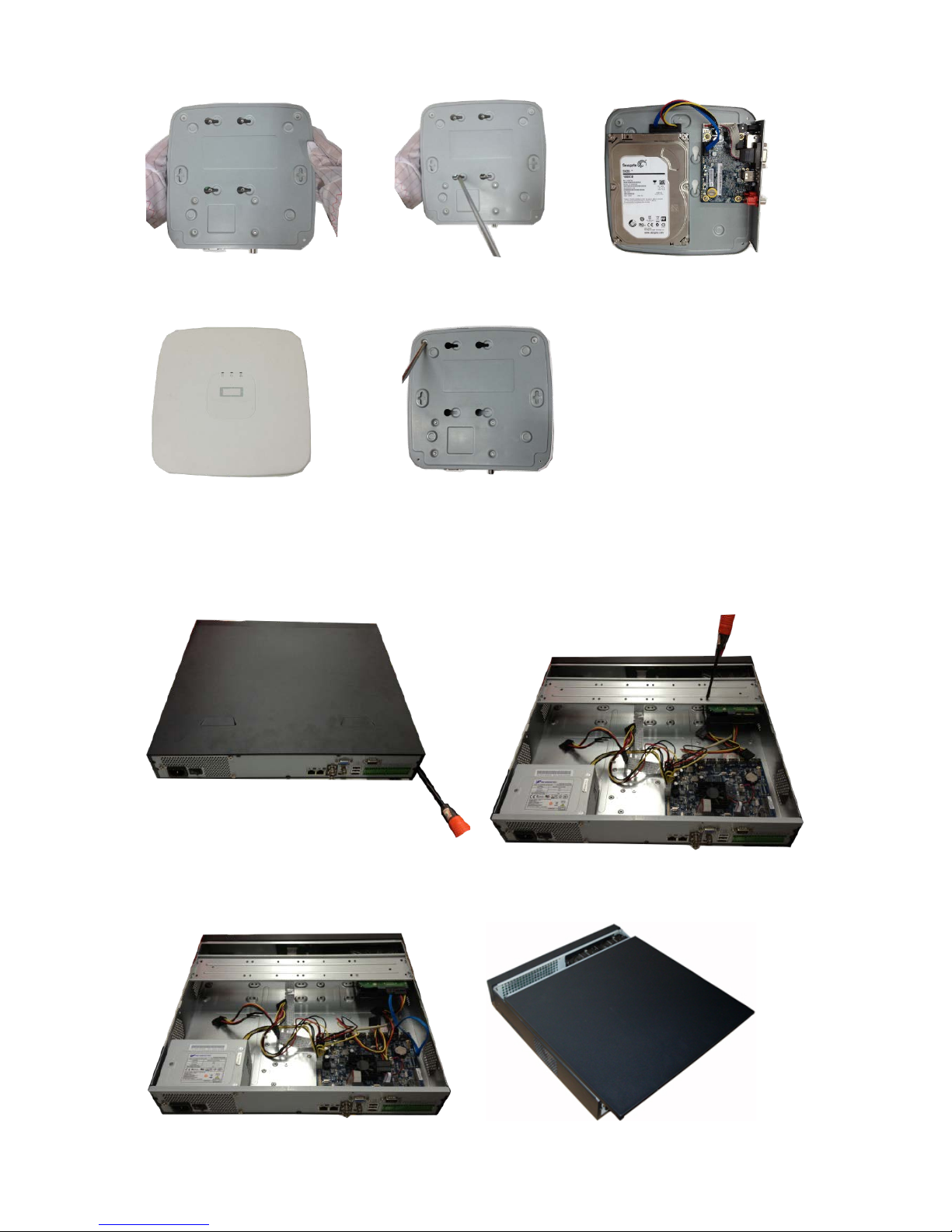
2
A
○
4
E A Turn the device upside down and
then turn the screws in firmly.
A
○
5
E A Fix the HDD firmly.
A
○
6
E A Connect the HDD cable and
power cable.
A
○
7
E A Put the cover in accordance with
the clip and then place the upper cover
back.
A
○
8
E A Secure the screws in the rear panel and the side panel.
1.4.2 Phoenix-323HP+ Series
① Use the screwdriver to loose the screws of the rear
panel and then remove the front cover.
② Put the HDD to the HDD bracket in the chassis
and then line up the four screws to the four holes
in the HDD. Use the screwdriver to fix the screws
firmly to secure HDD on the HDD bracket
③ Connect to the HDD data cable to the main board
④
After connect the cable, put the front cover back
Page 8
3
and the HDD port respectively. Loosen the power
cable of the chassis and connect another end of
the power cable to the HDD port.
to the device and then fix screws of the rear
panel.
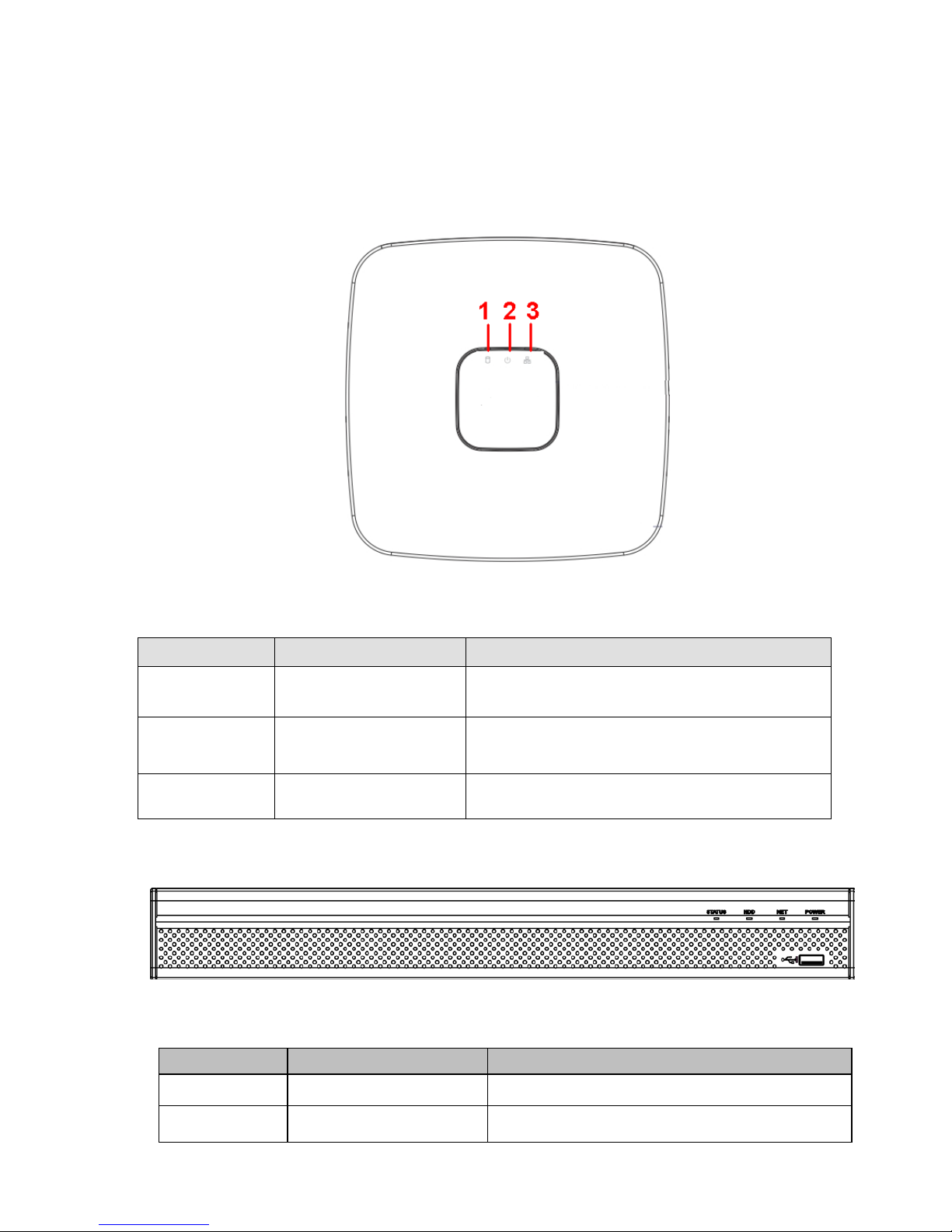
1.5 Front Panel
1.5.1 WiFI-NVR-4 Series
The front panel is shown as in Figure 1-1.
Figure 1-1
Please refer to the following she et for det ailed information.
SN
Name
Function
1
HDD status indictor light
The red light becomes on when H D D is a bnormal.
2
Power indicator light
The red light becomes on when the power
connection is OK.
3
Network status indicator
light
The red light becomes on when the network
connection is abnormal.
1.5.2 Phoenix-32HP+ Series
The series front panel is show n as in Figure 1-2.
Figure 1-2
Please refer to the following she et for front panel button information.
Icon
Name
Function
STATUS
Status indicator light
The blue light is on when the device is malfunction.
HDD
HDD status indicator
light
The blue light is on when the HDD is malfunction.
Page 9
4
Icon
Name
Function
NET
Network status indicator
light
The blue light is on when the network connection is
abnormal.
POWER
Power status indicator light
The blue light is on when the power connection is
OK.
USB2.0 port
Connect to peripheral USB 2.0 st or age device,
mouse, burner and etc.
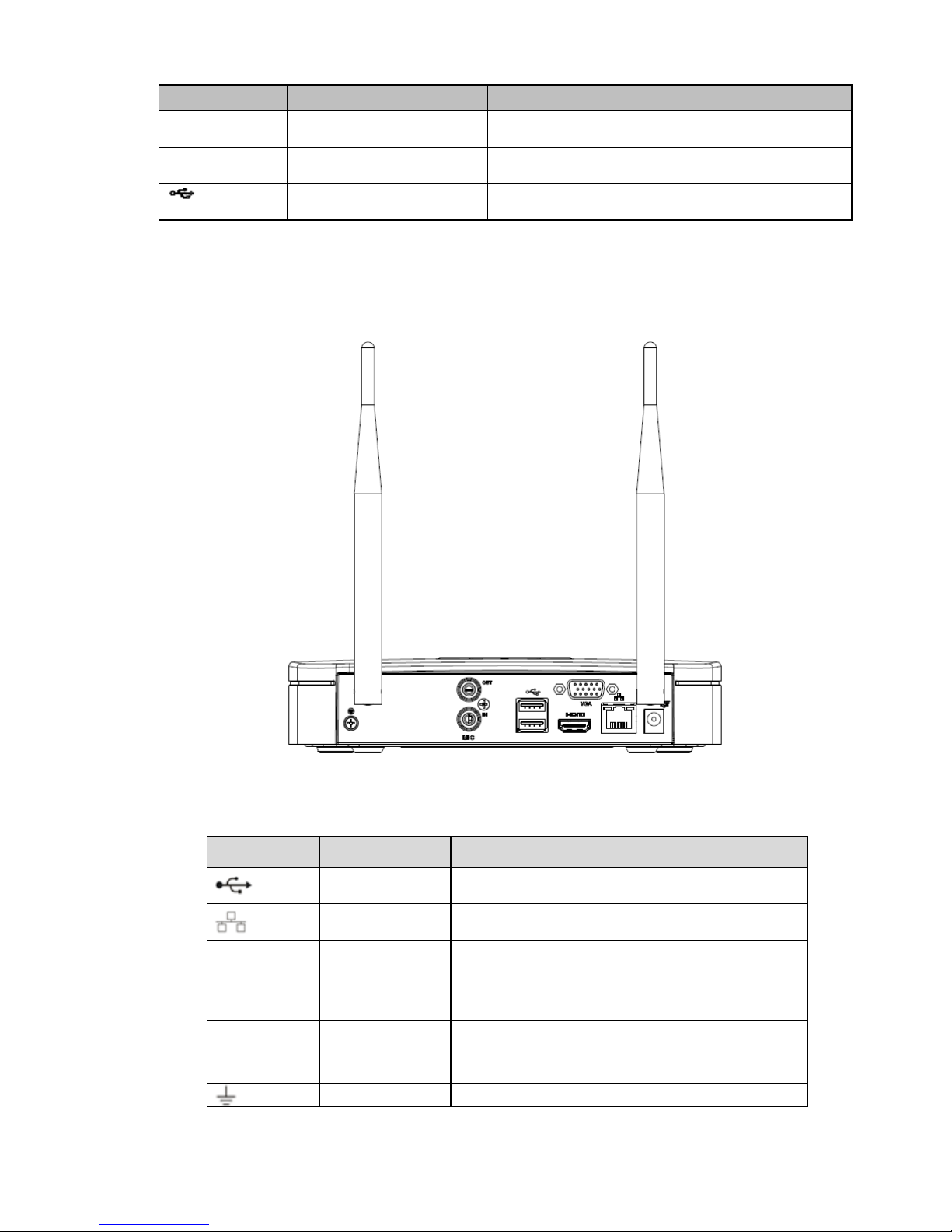
1.6 Rear Panel
1.6.1 WiFU-NVR-4 Series
The rear panel is shown as below. See Figure 1-3.
Figure 1-3
Please refer to the following she et for det ailed information.
Port Name Connection Function
USB2.0 port
USB2.0 port. Connect to mouse, USB storage
device, USB burner and et c.
Network port
10M/100Mbps self-adapti ve Ethernet port.
Connect to the network cable.
HDMI
High Definition
Media Interface
High definition audio and video signal output port.
It transmits uncompressed high definition video
and multiple-channel data to the HDMI port of the
display device. HDMI version is 1.4.
VGA
VGA video
output port
VGA video output port. Output analog video
signal. It can connect to the monitor to view
analog video.
GND
Ground end
Page 10
5
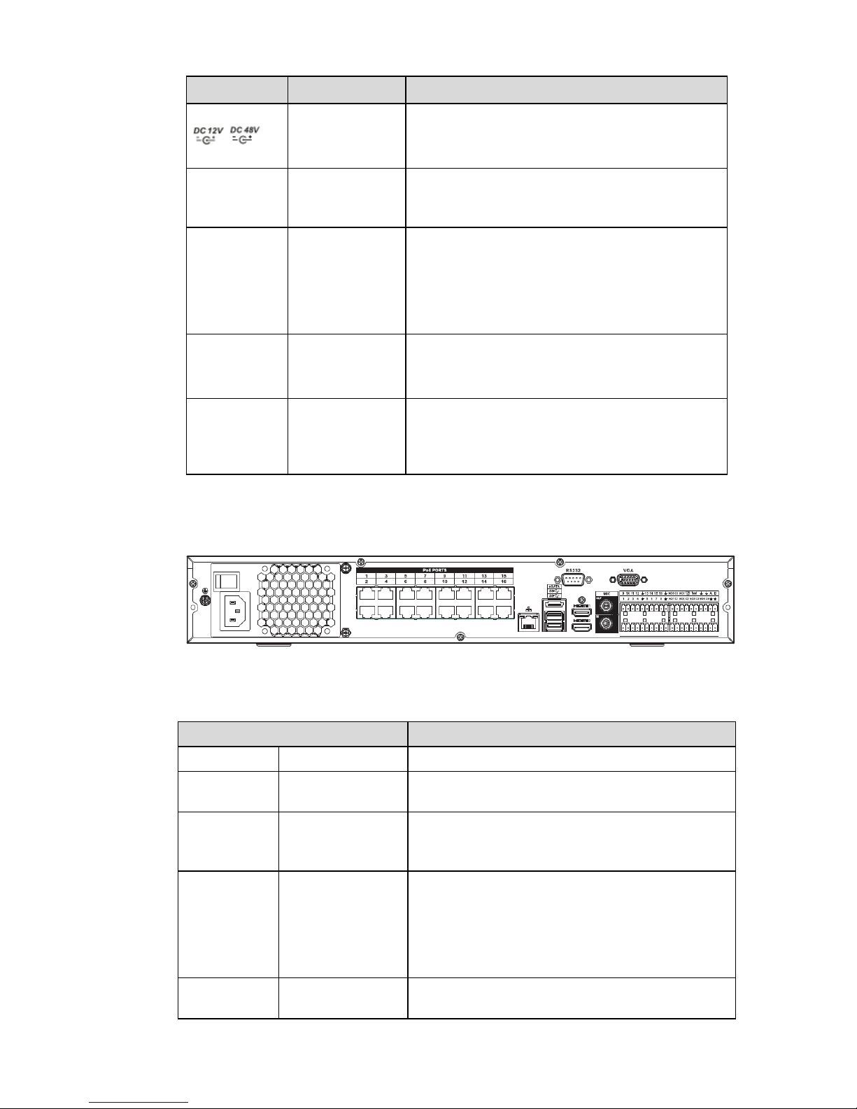
Port Name Connection Function
/
Power input port
Power socket.
For NVR41 series, input DC 12V/2A.
For NVR41-P series, input DC 4 8V/ 1.5A.
For NVR41-8P series, input DC 4 8V/ 2A.
MIC IN Audio input port
Bidirectional talk input por t . It is to receive the
analog audio signal output from the devices such
as microphone, pickup.
MIC OUT
Audio output
port
Audio output port. It is to output t he analog audio
signal to the devices such as t he sound box.
Bidirectional talk outp ut .
Audio output on 1-window video monitor.
Audio output on 1-window video playback.
PoE PORT
PoE port Built-in switch. Suppor t PoE function.
For PoE series product, you can use this port to
provide power to the network c amera.
Wireless AP
Support wireless hotspot function. Use WIFI to
connect to the network camera when there is a
hotspot.
For 41-W series only.
1.6.2 Phoenix-32HP+ Series
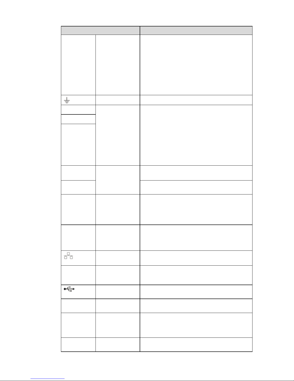
The series rear panel is shown as below. See Figure 1-4.
Figure 1-4
Please refer to the following she et for det ailed information.
Name Function
Power switch / Power on-off button
Power input
port
/ Input AC 100~240V.
MIC IN
Audio input port
Bidirectional talk input por t . It is to receive the
analog audio signal output from the devices such
as microphone, pickup.
MIC OUT
Audio output port
Audio output port. It is to output t he analog audio
signal to the devices such as t he sound box.
Bidirectional talk output.
Audio output on 1-window video monitor.
Audio output on 1-window video playback.
VIEDEO
OUT
Video output port
CVBS output
Page 11
6
Name Function
1~16
Alarm input port
1~16
There are four groups. The first gr oup is from
port 1 to port 4, the second group is from port
5 to port 8, the third group is from 9 to 12, and
the fourth group is from 13 to 16. They are to
receive the signal from the exter nal alarm
source. There are two types; NO ( normal
open)/NC (nor mal close).
When your alarm input dev ice is using
external power, please make sure the device
and the NVR have the same groun d.
Video output port
CVBS output
NO1
~NO5
Alarm output port
1~5
5 groups of alarm output ports. ( G r oup 1:port
NO1~C1,Group 2:port NO2~C2,Group
3:port NO3~C3, Group 4:port NO4~C4,
Group 5: port NO5, C5, NC5).O ut put alarm
signal to the alarm device. Please make sure
there is power to the external alarm device.
NO: Normal open alarm output por t .
C: Alarm output public end.
NC: Normal close alarm output por t .
C1
~C5
NC5
A
RS-485
communication
port
RS485_A port. It is the cable A. You can connect
to the control devices such as speed dome PTZ.
B
RS485_B.It is the cable B. You can connect to the
control devices such as speed d ome PTZ.
CTRL 12V
/ Controller 12V power output. It is to control the on-
off alarm relay output. It can be used to control the
device alarm output. At the same time, it can also
be used as the power input source of some
devices such as the alarm detect or .
+12V /
+12V power output port. It can pr ovide the power
to some peripheral devices such as the camera or
the alarm device. Please note t he supplying power
shall be below 1A.
Network port
10M/100M/1000Mbps sel f-adaptive Ethernet port.
Connect to the network cable.
eSATA eSATA port External SATA port. It can connect to the device of
the SATA port. Please jump the HDD when there is
peripheral connected HD D.
USB2.0 port
USB2.0 port. Connect to mouse, USB storage
device, USB burner and et c.
RS-232
RS232 debug
COM.
It is for general COM debug to configure IP
address or transfer transp ar ent COM dat a.
HDMI
High Definition
Media Interface
High definition audio and vide
o signal output port.
It transmits uncompressed high definition video
and multiple-channel data to the HDMI port of the
display device. HDMI version is 1.3
VGA
VGA video output
port
VGA video output port. Output analog video signal.
It can connect to the monitor to view analog video.
Page 12

7
Name Function
PoE PORTS 8 Po E ports
Built-in Switch. Supp or t PoE.
The 8 PoE ports series products s upports total 48V
120W power. One PoE port max supports 15W.
PoE PORTS 16 Po E ports
Built-in Switch. Supp or t PoE. The 16 PoE ports
series products supports total 150W power. One
PoE port max supports 15W.
Page 13
8
2 GUI Operation
2.1 Boot up
Caution
Before the boot up, please make sur e:
For device security, pl ease connect the NVR to the power adapter first and then connect t he
device to the power socket.
The rated input voltage mat ches the device power on-off b ut t on. Please make sure the power
wire connection is OK. Then cl i ck the power on-off button.
Always use the stable curr ent, if necessary UPS is a best alt er native measure.
Please follow the steps listed below t o boot up the device.
Connect the device to the monitor and then connect a mouse.
Connect power cable.
Click the power button at the front or r ear panel and then boot up the device. After device booted up,
the system is in mult ip le-channel display mode by default.
2.2 Login
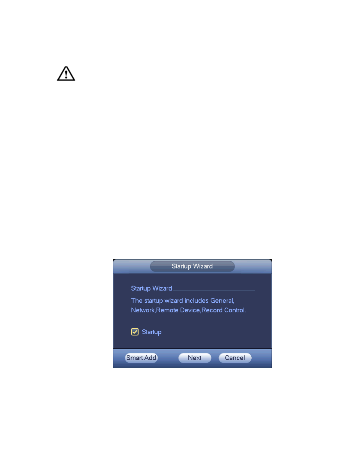
After device booted up, the system goes t o startup wizar d inter f ac e. See Figure 2-1
Click Cancel or Next Step button, you can see system goes to login interface.
Tips
Check the box Startup button here, system goes to st ar t up w izard again when it boots up the next
time.
Cancel the Startup button, system goes to the login interface dir ec t ly when it boots up the next time.
Figure 2-1
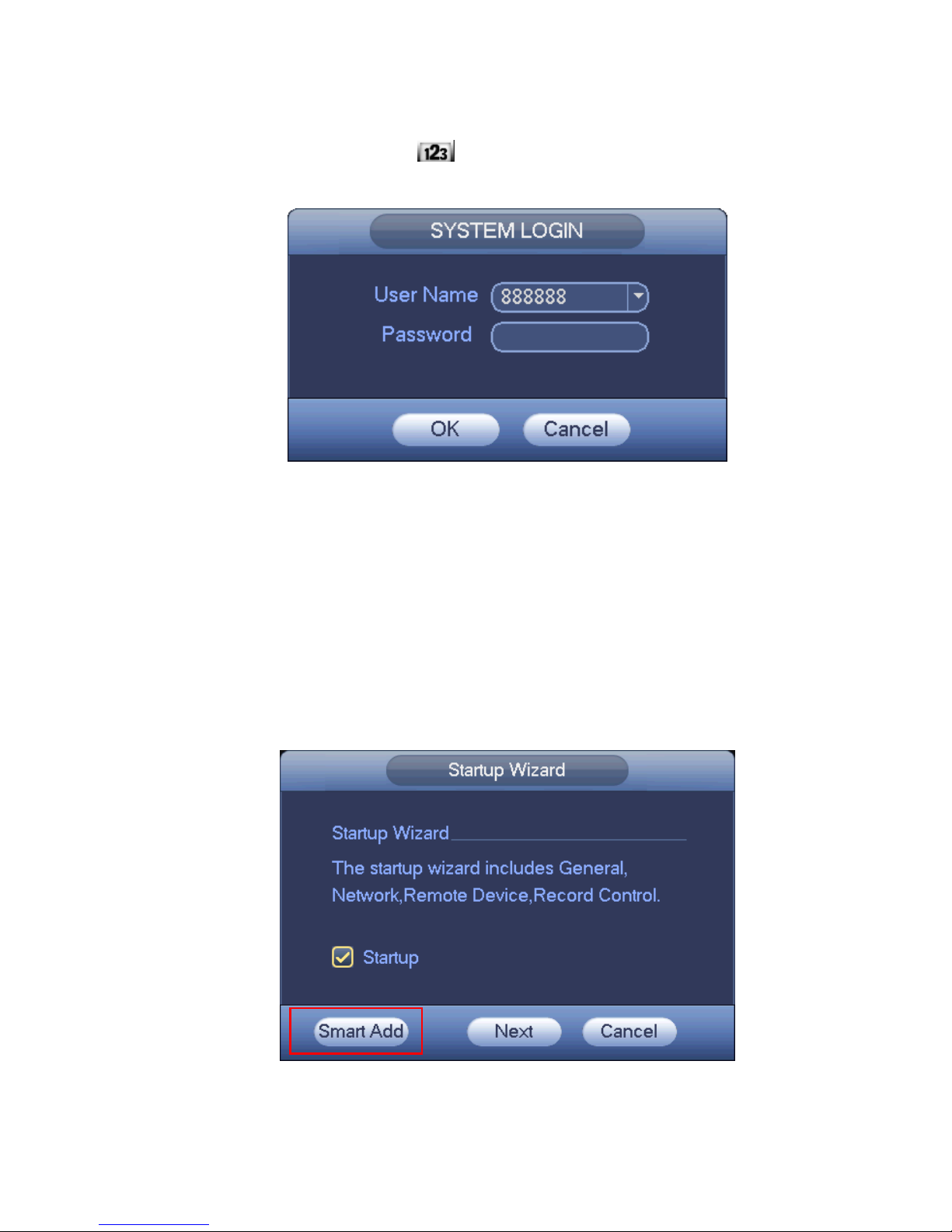
Click Cancel button or Next Step, you can see t he l ogin interface. Please input user name and password.
See Figure 2-2.
System consists of four ac count s :
Username: admin. Password: admin.
Username: 888888. Password: 888888.
Page 14
9
Username: 666666. Password: 666666.
Username: default. Password: default.
You can use USB mouse to input. Click
to switch between numer al, English character
(small/capitalized) and denotation.
Figure 2-2
Important:
For security reason, please modify password afte r you first login.
Within 30 minutes, three times login failure will result in system alarm and five times login failure
will result in account lock!
2.3 Smart Add
When the network camera(s) and the NVR are in the same router or s w itc h, you can use smart add
function to add all network cameras to the N VR at the same time.
There are two ways for you to go to t he s m art add interface.
From the startup wizard, click Smart add button. See Figure 2-3.
Figure 2-3
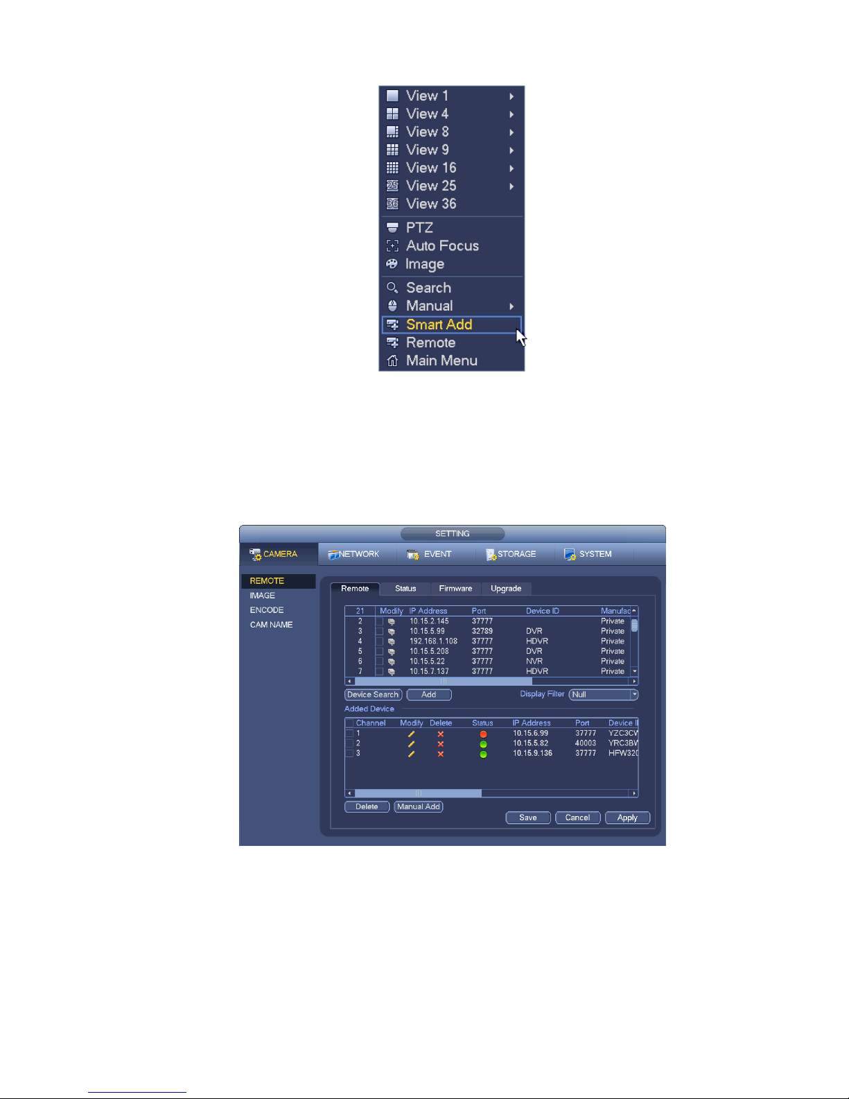
On the preview interface, right click mouse and then select Smart add. See Figure 2-4.
Page 15
10
Figure 2-4
Please refer to the user’s manual for detailed information.
2.4 Remote Device
From Main menu->Setting->Camera->Remote device or right click mouse on the preview interface and
then select remote device item, you can see the following interface. See Figure 2-5.
Figure 2-5
Tips
In the preview interface, for t he channel of no IPC connection, you can click the icon “+” in the centre of
the interface to quickly go to t he Remote Device interface. See Figure 2-6.
Page 16

11
Figure 2-6
Click Device Search button, you can view the s earched IP addresses at the top pane o f t he i nt er f ac e.
Double click an IP address or check one IP address and then click Add button, you can add current dev ice
to the bottom pane of the interfac e. System supports batch add fun ct ion.
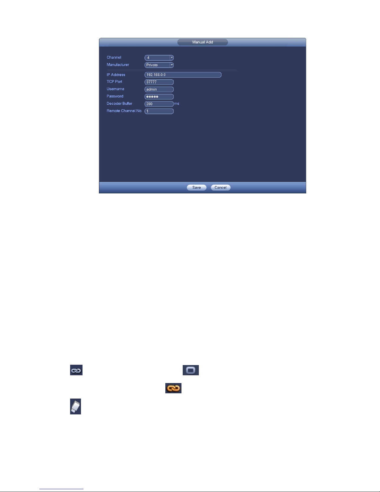
Click Manual Add button,
y
ou can add a device
directly. See Figure 2-7.
Important
Please note the manual add fu nc t i on is for ClearView, Panasonic, Sony, Dynacolor, Samsung, AXIS,
Arecont, ONVIF and custom. When the type is the custom, you can just input URL address, us er name
and password connect to the netw ork camera without consid er i ng net work camera manufact ur e. Pl ease
contact your network camer a m anufacturer for the URL address.
Page 17
12
Figure 2-7
2.5 Schedule
Note:
You need to have proper rights to implement the following operations. Please make sure the HDDs
have been properly installed.
After the system booted up, it is in default 24-hour regular mode. You can set record type and time in
schedule interface.
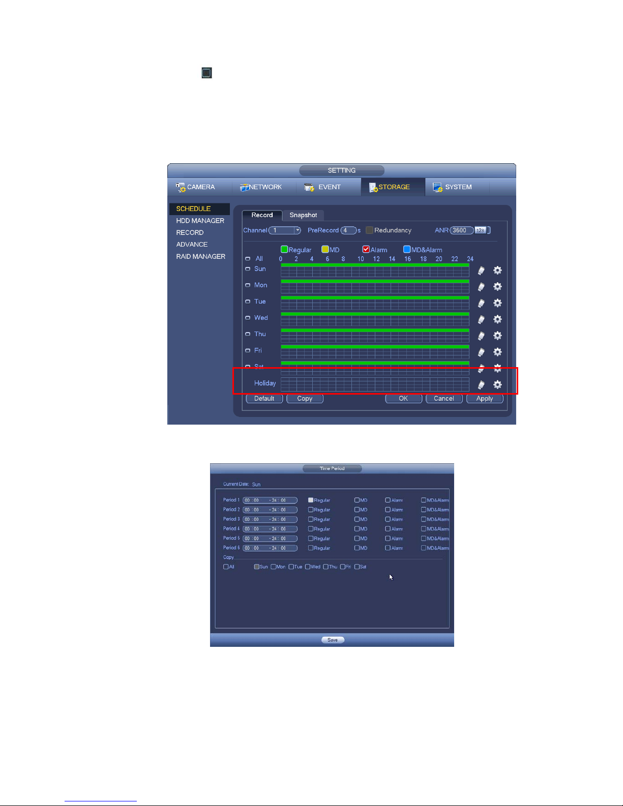
In the main menu, from Main menu->Setting->Storage->Schedule, you can go to schedule menu. See
Figure 2-11. There are total six periods.
Please note you need to go to Main menu->Setting->System->General->Holida y to se t holida y da te fi rst ,
otherwise, there is no holiday setup item.
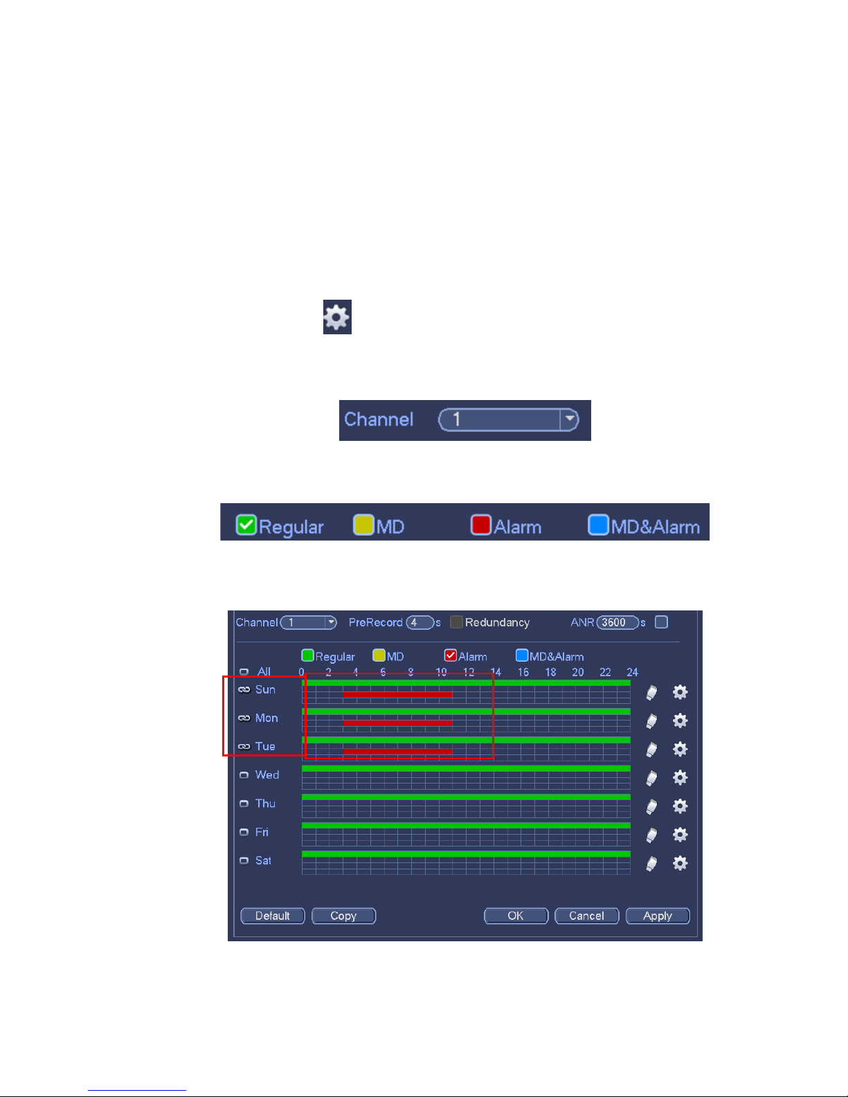
Channel: Please select the channel number first. You can select “all” if you want to set for the whole
channels.
: Sync connection icon. Select icon of several dates, all checked items can be edited or
together. Now the icon is shown as
.
: Click it to delete a record ty pe from on e period.
Record Type: Please check the box to select corresponding record type. There are four types:
Regular/MD (motion detect)/Alarm/MD&Alarm.
Week day: There are eight options: ranges from Saturday to Sunday and all.
Page 18
13
Holiday: It is to set holiday setup. Please note you need to go to the General interface (Main Menu-
>Setting->System->General) to add holiday first. Otherwise you can not see this item.
Pre-record: System can pre-record the video before the event occurs into the file. The value ranges
from 1 to 30 seconds dependi ng on the bit stream.
Redundancy: System supports redundancy backup function. It allows you backup recorded file in two
disks. You can highlight Redundancy button to activate this function. Please note, before enable this
function, please set at least one HDD as redundant. (Main menu->Setting->Storage->HDD Manager).
Please note this function is null if there is only one HDD.
ANR: It is to save video to the SD card of the network camera in case the network connection fails.
The value ranges from 0s~43200s. After the network connection resumed, the system can get the
video from the SD card and there is no risk of record loss.
Period setup: Click button
after one date or a holiday, you can see an interface shown as in
Figure 2-12.There are four record types: regular, motion detection (MD), Alarm, MD & alarm.
Please following the steps listed below to draw the period manually.
a) Select a channel you want to set. See Figure 2-8.
Figure 2-8
b) Set record type. See Figure 2-9.
Figure 2-9
c) Please draw manually to set record period. There are six periods in one day. See Figure 2-10.
Figure 2-10
Page 19
14
Please check the box to select the corresponding function. After completing all the setups plea se click
save button, system goes back to the previous menu.
There are color bars for your reference. Green color stands for regular recording, yellow color stands
for motion detection and red color stands for alarm recording. The white means the MD and alarm
record is valid. Once you have set to record when the MD and alarm occurs, system will not record
neither motion detect occurs nor the alarm occurs.
Figure 2-11
Figure 2-12
2.6 Realtime Playback
Preview control int erface
Page 20
15
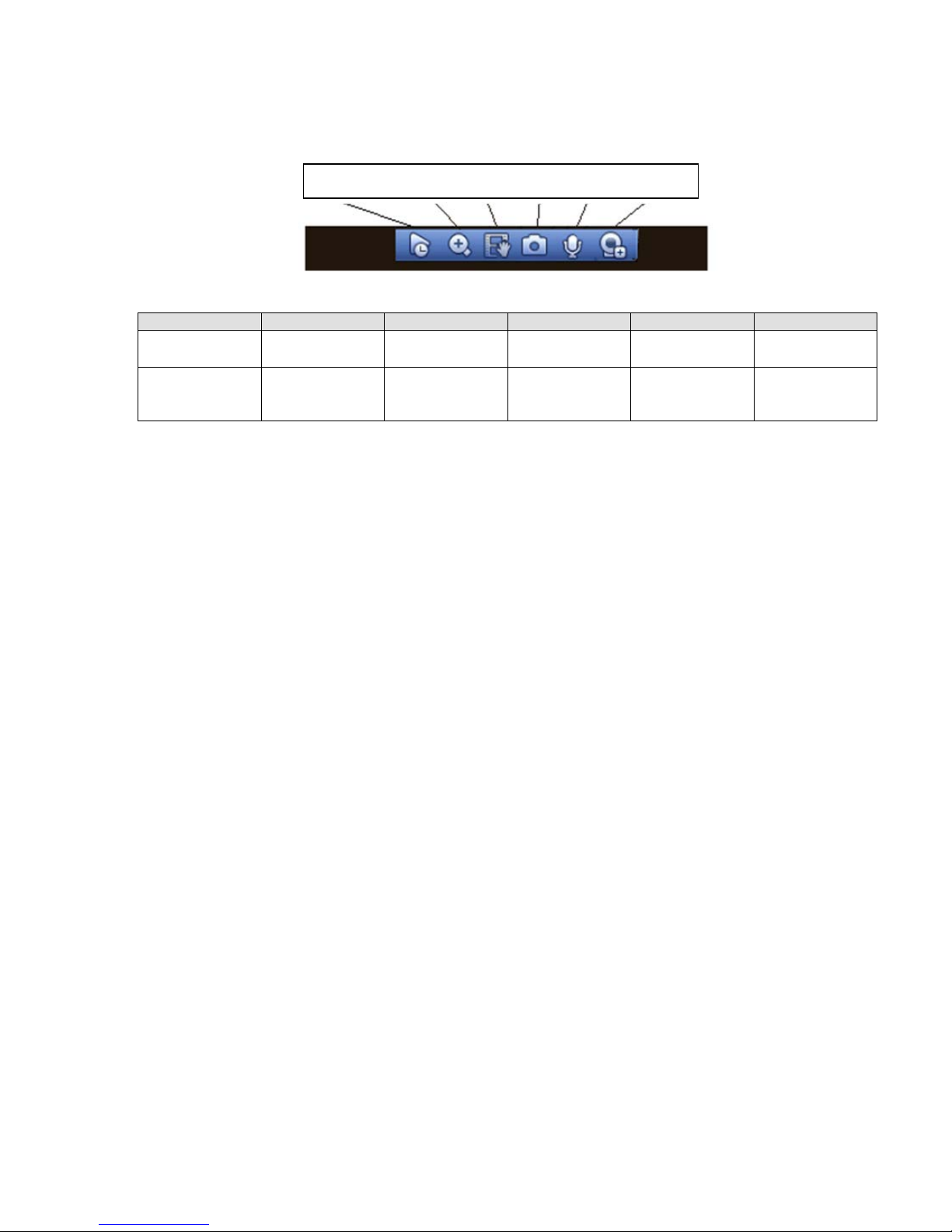
Move you mouse to the top centre of the video of current channel, you can see system pops up the
preview control interface. See Figure 2-13. If your mouse stays in this area for more than 6 seconds
and has no operation, the control bar automatically hides.
Figure 2-13
SN
Name
SN
Name
SN
Name
1
Realtime
playback
2 Digital zoom 3 Manual record
4
Manual
Snapshot
5
Bidirectional
talk
6
Remote device
Realtime playback button is to playback the previous 5-60 minutes record of c urrent channel.
Please go to the Main Menu->Setting->System->General to set real-time playback time.
System may pop up a dialogue box if there is no such record in current channel.
1 2 3 4 5 6
Page 21

16
3 Web Operation
Important
Slightly difference may be found in the interface due to different series.
The following operation is base d on 32-c ha nnel seri es product.
This series NVR product support the Web access and management via PC.
Web includes several modules : Monitor channel preview, recor d sear ch, alarm setup, system con f iguration,
PTZ control, monitor window and etc.
3.1 Network Connection
Before web client operation, please check the following items:
Network connection is right
NVR and PC network setup is right. Please refer to networ k setup(ma in menu->setting->network)
Use order ping ***.***.***.***(* NVR IP address) to check connection is OK or not . Usually the return
TTL value should be less than 255.
Open the IE and then input NVR IP address.
System can automatically download latest web control and the new version can over w r ite the previous
one.
If you want to un-install the w eb cont r ol, please run uninstall webrec2.0.bat. Or you can go to
C:\Program Files\webrec to remove single folder. Please note, before you un-install, please close all
web pages, otherwise the un-installation might result in err or .
Current series product su ppor t s various browsers such as Safari, firebox browser, Google browser.
Device only support 1-channel monitor on the Apple PC.
About PoE addre s s s etup, operation and allocati on.
1) Insert PoE
After you insert PoE, device may try t o set a corr esponding IP address of the Switch networ k ad apt er . First ,
system tries to set via arp ping. It then uses DHCP if it finds the DHCP is en abled. After successfully set IP
address, system may use Sw itch t o s end out broadcast, syst em thin k s t he connection is OK when there i s
any response. Now system is t rying to login the newly found IPC. N ow please check the interface, you can
see the corresponding digit al channel is active now. You can see a small PoE icon at the top left corner.
You can see the PoE channel, Po E por t in formation and etc from the connect ion list of the remote device
interface (Chapter 5.6.11 in the User’s Manual). For the IP search list, you need to click the IP searc h t o
display or refresh.
2) Remove PoE
After you removed PoE, you can see the corresponding digita l channel becomes idle (disable). On the
remote device interface, it is removed from the connected list. For the I P search list, you need to click the
IP search to refresh.
3) After you insert PoE, syst em fo ll ow s t he pr inciples listed below to map channel.
a) If it is your first time to insert PoE, system can map it to the first idle channel. After map, the
channel can memorize the MAC address of the IPC. It is a <Channel>---<IPC mac> map. If
current channel does not conn ect t o other device, system can memor ize current MAC
Page 22
17
address, otherwise it can r efresh to the newly added device and memorize the <PoE port>--<Channel>.
b) If it is your second time to insert t he PoE, system can check the saved MAC address
according to <Channel>---<IPC mac> map to make sure curr ent I PC has connected or not. If
system finds the previous in formation and the channel is idle, system can map it to the
previously used channel. Otherwise system goes to the next step.
c) Thirdly, according to the <PoE port>---<Channel> map, system can know the prev ious
mapping channel of curre nt PoE port. System can select curre nt channel if it is free.
Otherwise, it goes to the next st ep:
d) Fourthly, system goes to fi nd t he f ir st id le channel it can get.
Generally speaking, once you insert PoE, system follow t he s t eps listed above to find the channel
available.
4) When you insert PoE, all channels are in use now.
System can pop up a dialogue box f or you to select a channel to overwr it e. The title of the pop-up interf ace
is the name of the current operation PoE port. In this interface, All PoE c hannel become grey and can no t
select.
3.2 Login
Open IE and input NVR address in the address column. For exa m ple, i f your NVR IP is 10.10.3.16, then
please input http:// 10.10.3.16 in IE address column.
System pops up warning information to ask you whether install Web plug-in or not. Please click yes button.
If you can’t download the ActiveX file, please modify your IE security setup.
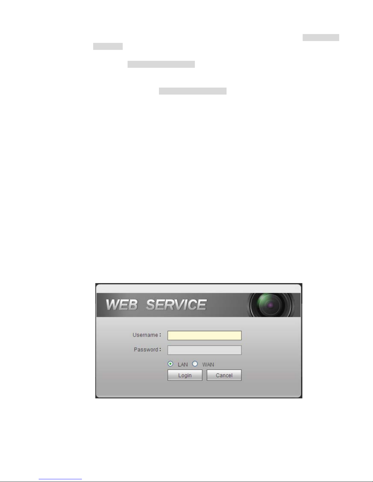
After installation, the interface is shown as below. See Fi gure 3-1.
Please input your user name a nd password.
Default factory name is admin and password is admin.
Note: For security reasons, please modify your password after you first login.
Figure 3-1
3.3 Main Window
3.3.1 LAN Login
Page 23
18
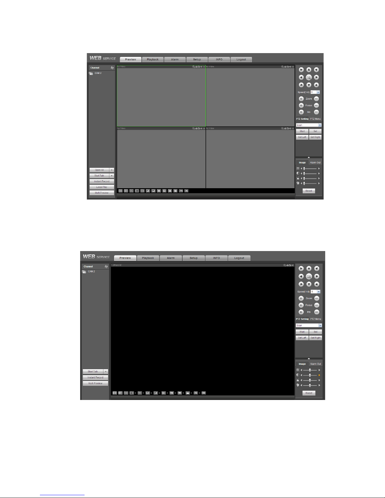
For the LAN mode, after you logged in, you can see the main window. See Figure 3-2.
Click the channel name on the le ft side; you can view the real-ti me v ide o.
Figure 3-2
3.3.2 WAN Login
In WAN mode, after you logged in, t he i nterface is shown as below. See Figure 3-3.
Figure 3-3
For detailed operation information, please refer to the User’s Manual included in the resources CD.
Note
Page 24

19
For detailed opera t ion introducti on, please refer t o our resource CD i ncluded in your pa ckage
for electronic version of the User’s Manual.
Slight difference may be found in user i nt er f ace.
All the designs and softwar e her e are subject to change with out pri or written notice.
All trademarks and registered trademarks are the properties of their respective owners.
If there is any uncertaint y or controversy, please refer to the final explanation of us.
Please visit our website or co nt act your local service engine er f or m ore information.
 Loading...