

Page 1
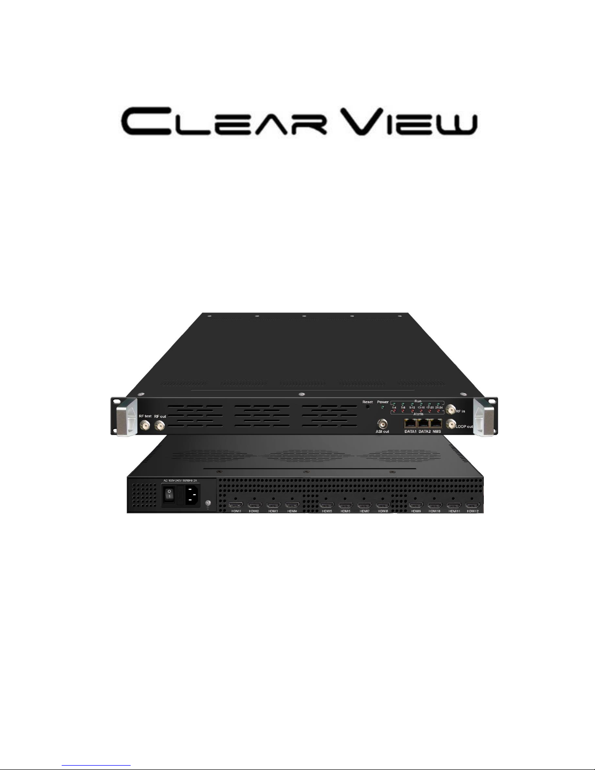
KR423I
Encoder Modulator User Manual
Page 2

About This Manual
Intended Audience
This user manual has been written to help people who have to use, to integrate and to
install the product. Some chapters require some prerequisite knowledge in electronics and
especially in broadcast technologies and standards.
Disclaimer
No part of this document may be reproduced in any form without the written permission of
the copyright owner.
The contents of this document are subject to revision without notice due to continued
progress in methodology, design and manufacturing. CLEARVIEW shall have no liability
for any error or damage of any kind resulting from the use of this document.
Copy Warning
This document includes some confidential information. Its usage is limited to the owners
of the product that it is relevant to. It cannot be copied, modified, or translated in another
language without prior written authorization from CLEARVIEW.
Page 3

KR423I Encoder Modulator User Manual
Directory
CHAPTER 1 INTRODUCTION ................................................................................................................... 1
1.1 PRODUCT OVERVIEW ............................................................................................................................... 1
1.2 KEY FEATURES ........................................................................................................................................ 1
1.3 SPECIFICATIONS ....................................................................................................................................... 2
1.4 PRINCIPLE CHART .................................................................................................................................... 2
CHAPTER 2 INSTALLATION GUIDE ........................................................................................................... 6
2.1 GENERAL PRECAUTIONS .......................................................................................................................... 6
2.2 POWER PRECAUTIONS .............................................................................................................................. 6
2.3 DEVICE’S INSTALLATION FLOW CHART ILLUSTRATED AS FOLLOWING ..................................................... 6
2.4 ENVIRONMENT REQUIREMENT ................................................................................................................ 6
2.5 GROUNDING REQUIREMENT .................................................................................................................... 7
CHAPTER 3 WEB NMS OPERATION ......................................................................................................... 8
4.1 ENCODER LOGIN ...................................................................................................................................... 8
4.2 ENCODER OPERATION .............................................................................................................................. 9
CHAPTER 4 TROUBLESHOOTING ........................................................................................................... 24
CHAPTER 5 PACKING LIST ..................................................................................................................... 25
Page 4

Page 5

ClearView Corp. Ltd. Page 1 / 29
KR423I Encoder Modualtor User Manual
Chapter 1 Introduction
1.1 Product Overview
KR423I is a professional high integration device which includes encoding,
multiplexing, scrambling and DVB-C/T modulation. It supports 12 HDMI (8 HDMI
optional) input, one DVB-C tuner input and 128 IP input with Data1(GE) and
Data2(FE) port. It also support DVB-C/T RF out with 4 adjacent carries
(50MHz~960MHz), and support Data1(GE) output port to support 4 MPTS out. This
full function device makes it ideal for small CATV head end system, and it’s a smart
choice for hotel TV system, entertainment system in sports bar, hospital, apartment…
1.2 Key Features
• 12 HDMI input, 1DVB-C tuner input
• 128 IP input over UDP and RTP protocol
• MPEG-4 AVC/H.264 Video encoding
• MPEG1 Layer II Audio encoding and support audio gain adjustment
• 4 groups multiplexing, 4 groups scrambling and 4 DVB-C RF carriers out
• 4 groups multiplexing and 4 DVB-T RF carriers out
• Support IP(MPTS only, DATA1 port only) output over UDP and RTP
• Support QR code, LOGO, OSD insertion
• Support “Null PKT Filter” function
• Excellent RF output performance index, MER≥40dB
• Support PID remapping
• Support accurate PCR adjusting
• Support PSI/SI editing and inserting
• Control via web management, and easy updates via web
• Lowest cost per channel, breakthrough price
Page 6
Page 2 / 29 ClearView Corp. Ltd.
KR423I Encoder Modulator User Manual
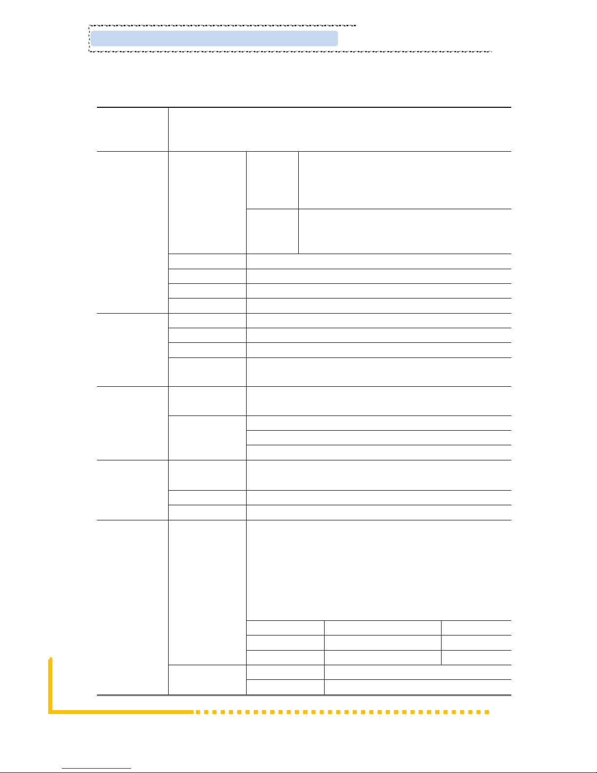
1.3 Specifications
Input
12 HDMI inputs(8 HDMI optional)
1 DVB-C Tuner, F type interface
DATA1 and DATA2,RJ45
Video
Resolution
In-put
1920×1080_60P, 1920×1080_60i,
1920×1080_50P, 1920×1080_50i,
1280×720_60P, 1280×720_50P,
720×576_50i,720×480_60i,
Out-put
1920×1080_30P, 1920×1080_25P,
1280×720_30P, 1280×720_25P,
720×576_25P,720×480_30P,
Encoding
MPEG-4 AVC/H.264
Bit-rate
1Mbps~13Mbps each channel
Rate Control
CBR/VBR
GOP Structure
IP…P (P Frame adjustment, without B Frame )
Audio
Encoding
MPEG-1 Layer 2
Sampling rate
48KHz
Resolution
24-bit
Bit-rate
64kbps,128Kbps,192kbps,224kbps,256kbps,320kbps,384
kbps
Multiplexing
Maximum PID
Remapping
180 input per channel
Function
PID remapping ( automatically or manually)
Accurate PCR adjusting
Generate PSI/ SI table automatically
Scrambling
Maximum
simulcrypt CA
4
Standard
EN300 429/ITU-T J.83A/B
Connection
Local/remote connection
Modulation
DVB-C
QAM Channel: 4
Standard: EN300 429/ITU-T J.83A/B
MER: ≥40db
RF frequency: 50~960MHz, 1KHz step
RF output level: -26~-1dBm (81~106 dbµV), 0.1dBm
Symbol Rate: 5.0Msps~7.0Msps, 1ksps stepping
Constellation: 16/32/64/128/256QAM
J.83A
J.83B
Constellation
16/32/64/128/256QAM
64/256 QAM
Bandwidth
8M
6M
DVB-T
Standard
EN300744
FFT mode
2K,
Page 7
ClearView Corp. Ltd. Page 3 / 29
KR423I Encoder Modualtor User Manual
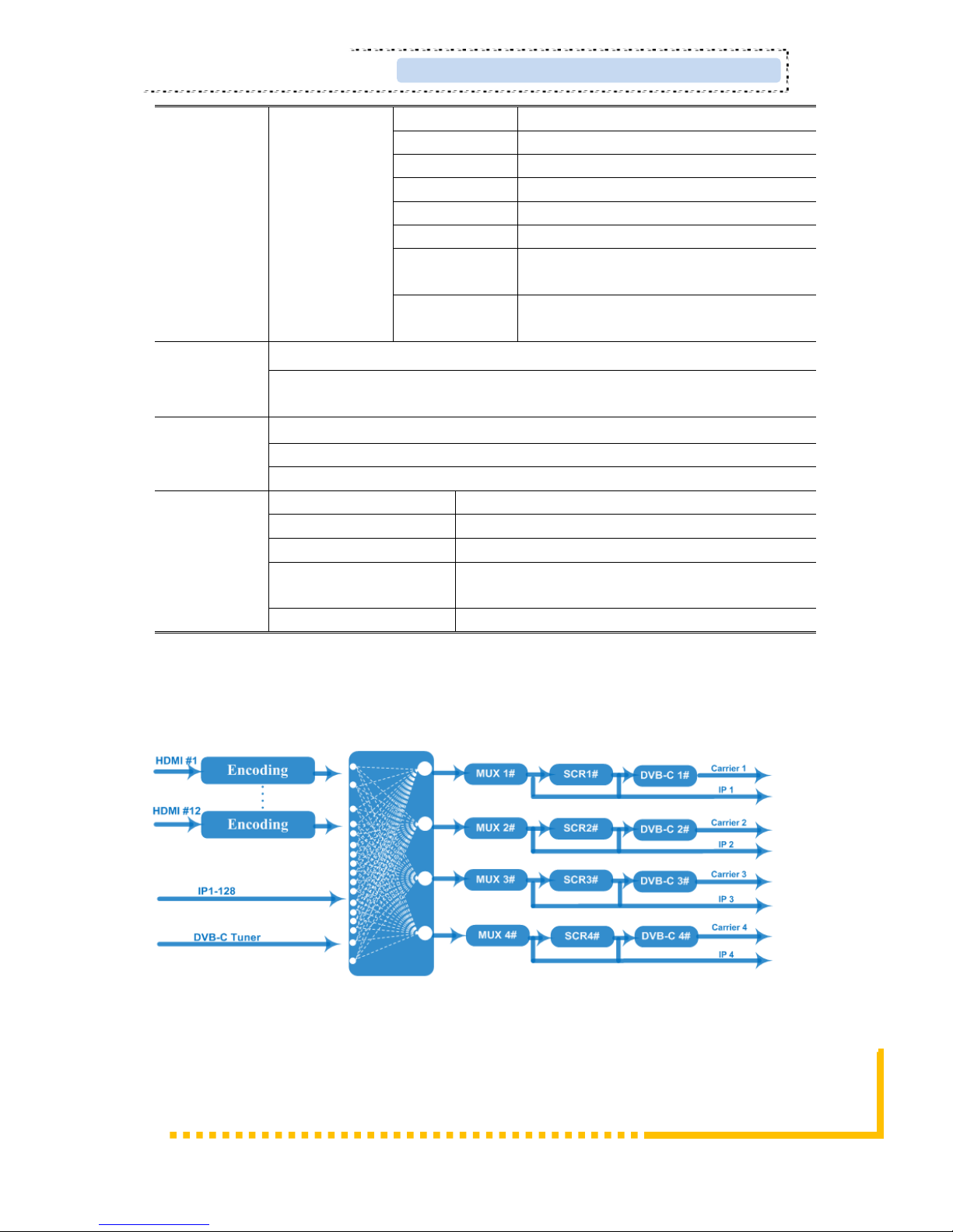
Bandwidth
6M, 7M, 8M
Constellation
QPSK, 16QAM, 64QAM
Guard Interval
1/4, 1/8, 1/16, 1/32
FEC
1/2, 2/3, 3/4, 5/6, 7/8
MER
≥42 dB
RF frequency
50~960MHz, 1KHz step
RF out
4*RF COFDM DVB-T out (4 carriers
combined output)
RF output
level
-28~ -3 dBm (77~97 dbµV), 0.1db step
Stream
output
RF output (F type interface)
4 IP output over UDP/RTP, 1*1000M Base-T Ethernet interface(Data1
only)
System
function
Network management(WEB)
Chinese and English language
Ethernet software upgrade
Miscellaneo
us
Dimension(W×L×H)
482mm×410mm×44mm
Approx weight
8kg
Environment
0~45℃(work);-20~80℃(Storage)
Power requirements
AC 110V± 10%, 50/60Hz, AC 220
±10%,50/60Hz
Power consumption
70W
1.4 Principle Chart
DVB-C RF out
Page 8
Page 4 / 29 ClearView Corp. Ltd.
KR423I Encoder Modulator User Manual
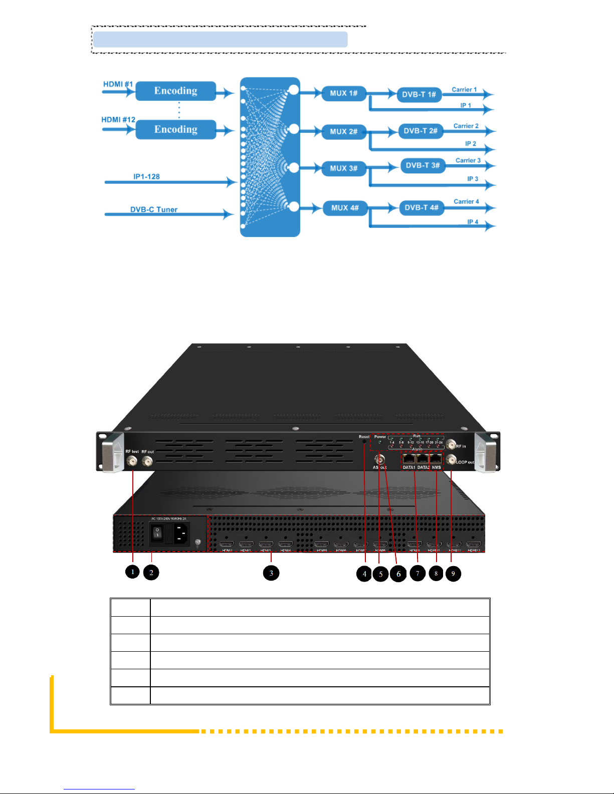
DVB-T RF out
1.5 Appearance and Description
Front and Rear Panel Illustration
1
RF test and RF out port
2
Port Power supply and Grounding Pole
3
12HDMI input
4
Reset Key/Data Port Indicator
5
Indicator
6
ASI output port(optional)
Page 9
ClearView Corp. Ltd. Page 5 / 29
KR423I Encoder Modualtor User Manual
7
DATA Port (for IP stream input/output)
8
NMS/CAS
9
RF in and Loop out
Page 10
Page 6 / 29 ClearView Corp. Ltd.
KR423I Encoder Modulator User Manual
Chapter 2 Installation Guide
This section is to explain the cautions the users must know in some case that possible
injure may bring to users when it’s used or installed. For this reason, please read all
details here and make in mind before installing or using the product.
2.1 General Precautions
✓ Must be operated and maintained free of dust or dirty.
✓ The cover should be securely fastened, do not open the cover of the products when the
power is on.
✓ After use, securely stow away all loose cables, external antenna, and others.
2.2 Power precautions
✓ When you connect the power source, make sure if it may cause overload.
✓ Avoid operating on a wet floor in the open. Make sure the extension cable is in good
condition
✓ Make sure the power switch is off before you start to install the device
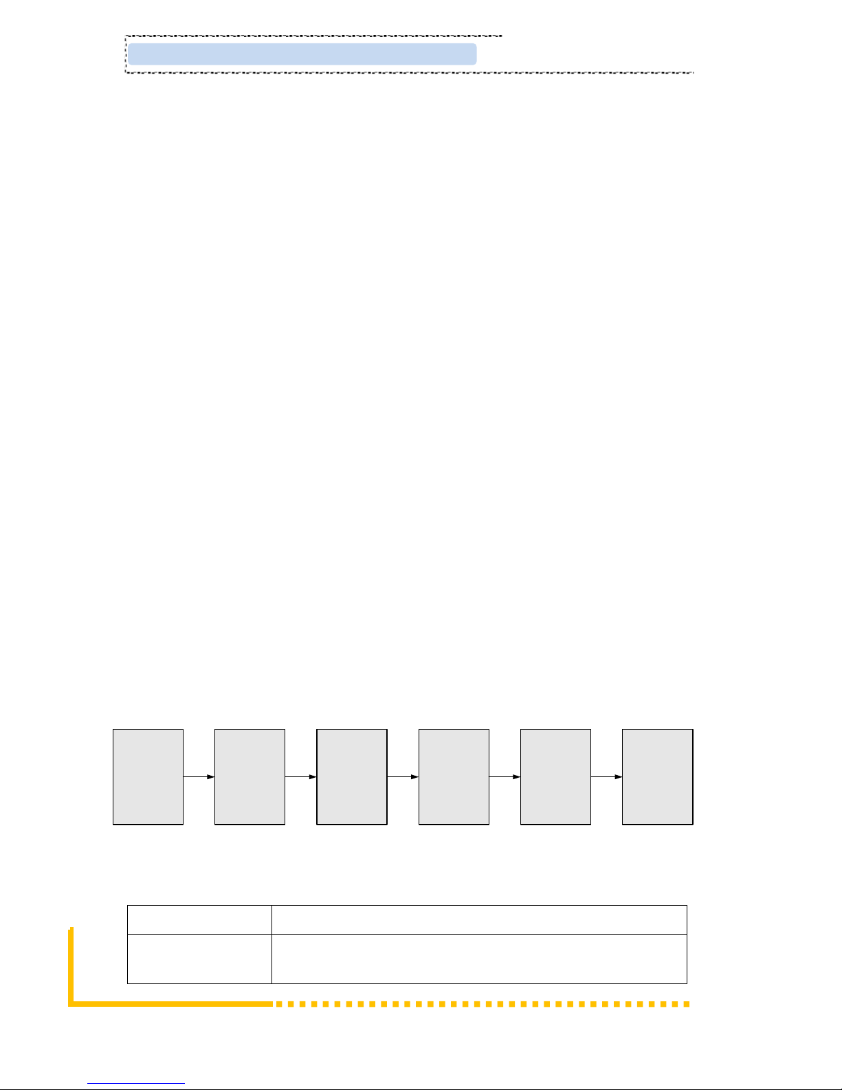
2.3 Device’s Installation Flow Chart Illustrated as following
Connecting
Grouding
Wire and
Power
Cord
Acquisition
Check
Installing
Device
Setting
Parameter
Running
Device
Connecting
Signal
cable
2.4 Environment Requirement
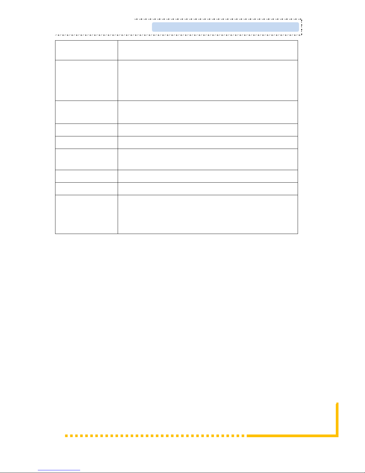
Item
Requirement
Machine Hall
Space
When user installs machine frame array in one machine hall,
the distance between 2 rows of machine frames should be
Page 11
ClearView Corp. Ltd. Page 7 / 29
KR423I Encoder Modualtor User Manual
1.2~1.5m and the distance against wall should be no less than
0.8m.
Machine Hall Floor
Electric Isolation, Dust Free
Volume resistivity of ground anti-static material:
1X10⁷~1X10¹⁰,Grounding current limiting resistance: 1M
(Floor bearing should be greater than 450Kg/㎡)
Environment
Temperature
5~40℃(sustainable ),0~45℃(short time),
installing air-conditioning is recommended
Relative Humidity
20%~80% sustainable 10%~90% short time
Pressure
86~105KPa
Door & Window
Installing rubber strip for sealing door-gaps and dual level
glasses for window
Wall
It can be covered with wallpaper, or brightness less paint.
Fire Protection
Fire alarm system and extinguisher
Power
Requiring device power, air-conditioning power and lighting
power are independent to each other. Device power requires
AC 110V±10%, 50/60Hz or AC 220V±10%, 50/60Hz. Please
carefully check before running.
2.5 Grounding Requirement
✓ All function modules’ good grounding is the basis of reliability and stability of devices.
Also, they are the most important guarantee of lightning arresting and interference
rejection. Therefore, the system must follow this rule.
✓ Grounding conductor must adopt copper conductor in order to reduce high frequency
impedance, and the grounding wire must be as thick and short as possible.
✓ Users should make sure the 2 ends of grounding wire well electric conducted and be
antirust.
✓ It is prohibited to use any other device as part of grounding electric circuit
✓ The area of the conduction between grounding wire and device’s frame should be no
less than 25 mm2.
Page 12
Page 8 / 29 ClearView Corp. Ltd.
KR423I Encoder Modulator User Manual
Chapter 3 WEB NMS Operation
User not only can use front buttons to set configuration, but also can control and set
the configuration in computer by connecting the device to web NMS Port. User
should ensure that the computer’s IP address is different from the NDS3542’s IP
address; otherwise, it would cause IP conflict.
4.1 Encoder login
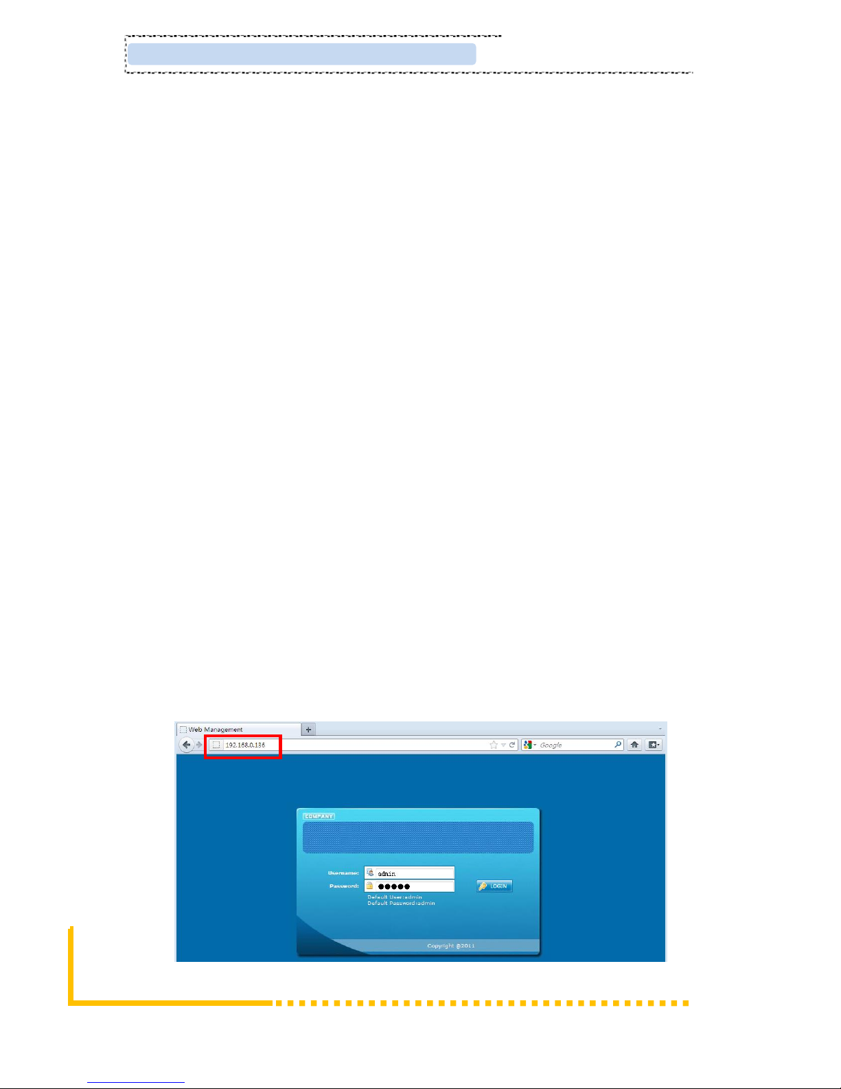
The default IP address of this device is 192.168.0.136. (We can modify the IP
through the front panel.)
Connect the PC (Personal Computer) and the device with net cable, and use ping
command to confirm they are on the same network segment.
I.G. the PC IP address is 192.168.99.252, we then change the device IP to
192.168.99.xxx (xxx can be 1 to 254 except 252 to avoid IP conflict).
Use web browser to connect the device with PC by inputting the Encoder &
Modulator’s IP address in the browser’s address bar and press Enter.
It will display the Login interface as Figure-1. Input the Username and Password
(Both the default Username and Password are “admin”.) and then click “LOGIN” to
start the device setting.
Figure-1
Page 13
ClearView Corp. Ltd. Page 9 / 29
KR423I Encoder Modualtor User Manual
4.2 Encoder Operation
Status
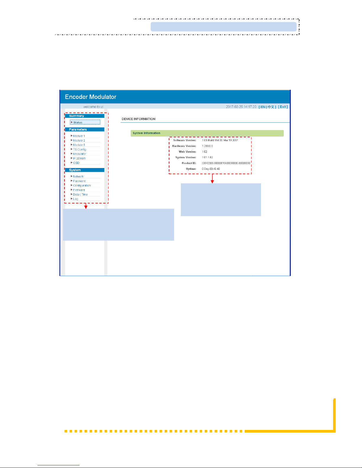
When we login into encoder module, it displays the status interface as Figure-2.
Figure-2
Parameters → Module 1-3
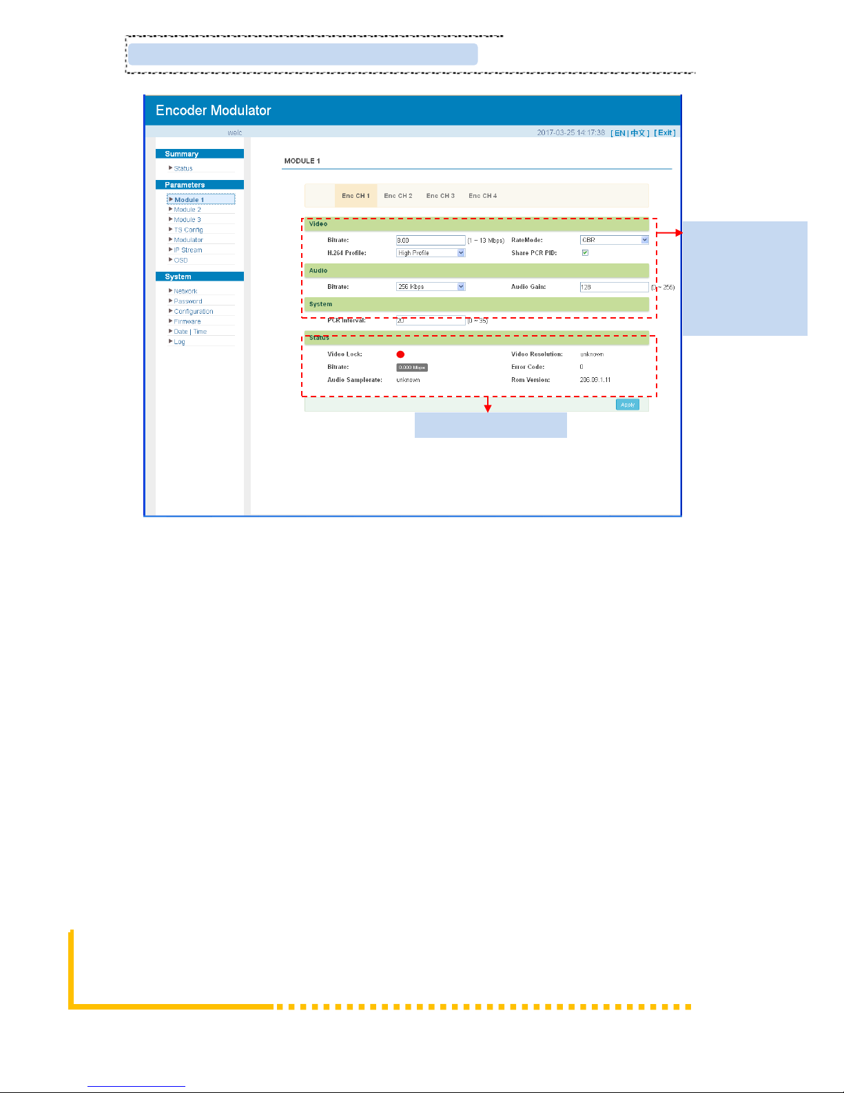
KR423Imaximum support up to 3 modules with 12 HDMI input. From the menu on left
side of the webpage, clicking “Module1-3”, it displays the information of each encoding
channel as Figure-3.
User can click any item here to enter
the corresponding interface to check
information or set the parameters.
Current software version
information
Page 14
Page 10 / 29 ClearView Corp. Ltd.
KR423I Encoder Modulator User Manual
Figure-3
Parameters → TS Config:
From the menu on left side of the webpage, clicking “TS Config”, it displays the interface
where users can configure the TS output parameters.
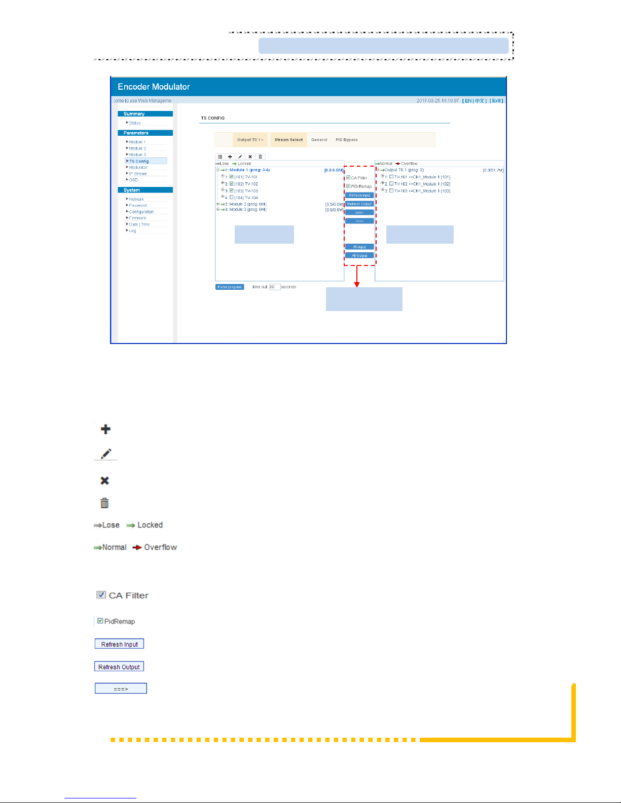
➢ TS Config→Stream select:
From the menu on up side of the webpage, clicking “Stream select”, it displays the
interface where users can select program(s) to multiplex out and modify program info.
(Figure-4)
General settings for
the Encoding
program: User can
edit any item listed
as needed.
Video Status read area
Page 15
ClearView Corp. Ltd. Page 11 / 29
KR423I Encoder Modualtor User Manual
Figure-4
Configure ‘Input Area’ and ‘Output Area’ with buttons in ‘Operation Area’. Instructions are
as below:
: To add input channel which can from GE1/GE2/Connector
: To edit the input channel
: To delete the input channel
: To delete all inputs channel
: To check input IP lock or not, green means current IP locked
: To check current TS overflow or not, red color means current TS
overflow, need reduce program
: To filter/not filter the source CA information
: To enable/disable the PID remapping
To refresh the input program information
To refresh the output program information
Select one input program first and click this button to transfer the selected
program to the right box to output.
Input Area
Output Area
Operation Area
Page 16
Page 12 / 29 ClearView Corp. Ltd.
KR423I Encoder Modulator User Manual
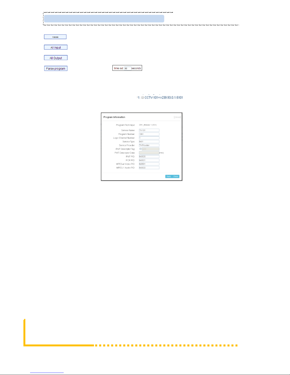
Similarly, user can cancel the multiplexed programs from the right box.
To select all the input programs
To select all the output programs
To parse programs time limitation of parsing input programs
➢ Program Modification:
The multiplexed program information can be modified by clicking the program in the
‘output’ area. For example, when clicking , it triggers a dialog box
(Figure 5) where users can input new information.
Figure-5
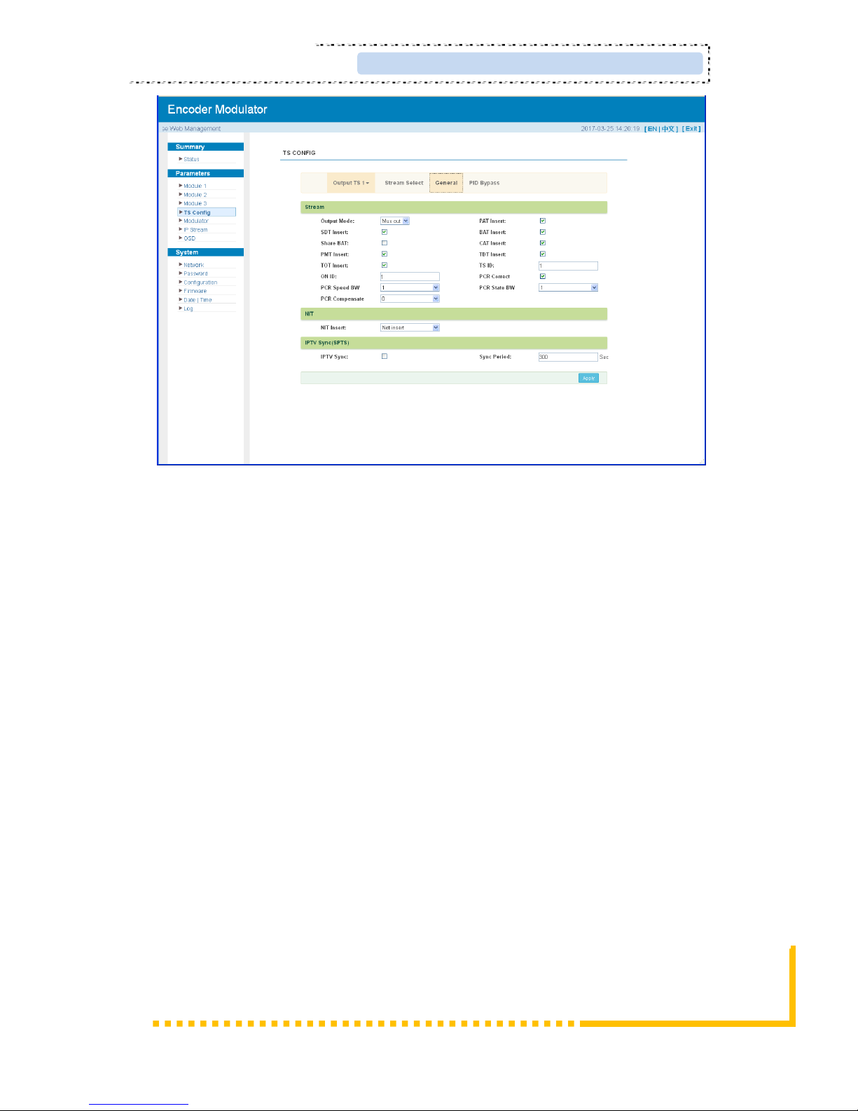
➢ TS Config→General:
From the TS Config menu on up side of the webpage, clicking “General”, it displays the
interface where users can set output mode, enable PSI/SI table out, NIT insert/VCT insert,
PCR correction. (Figure-6)
Page 17
ClearView Corp. Ltd. Page 13 / 29
KR423I Encoder Modualtor User Manual
Figure-6
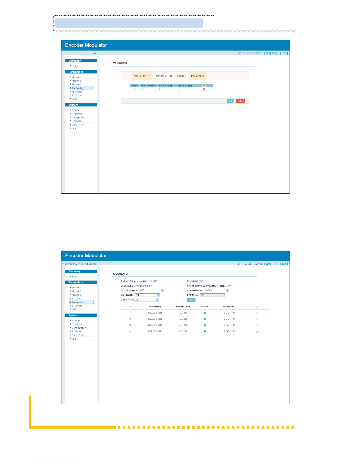
➢ TS Config→PID Bypass:
From the TS Config menu on up side of the webpage, clicking “PID Bypass”, it displays
the interface as Figure-7 where user can add PIDs to be passed, click the “+” symbol, input
current IP channel number, then input current IP source Pid and output Pid which is
customer needed , then click “set”
Page 18
Page 14 / 29 ClearView Corp. Ltd.
KR423I Encoder Modulator User Manual
Figure-7
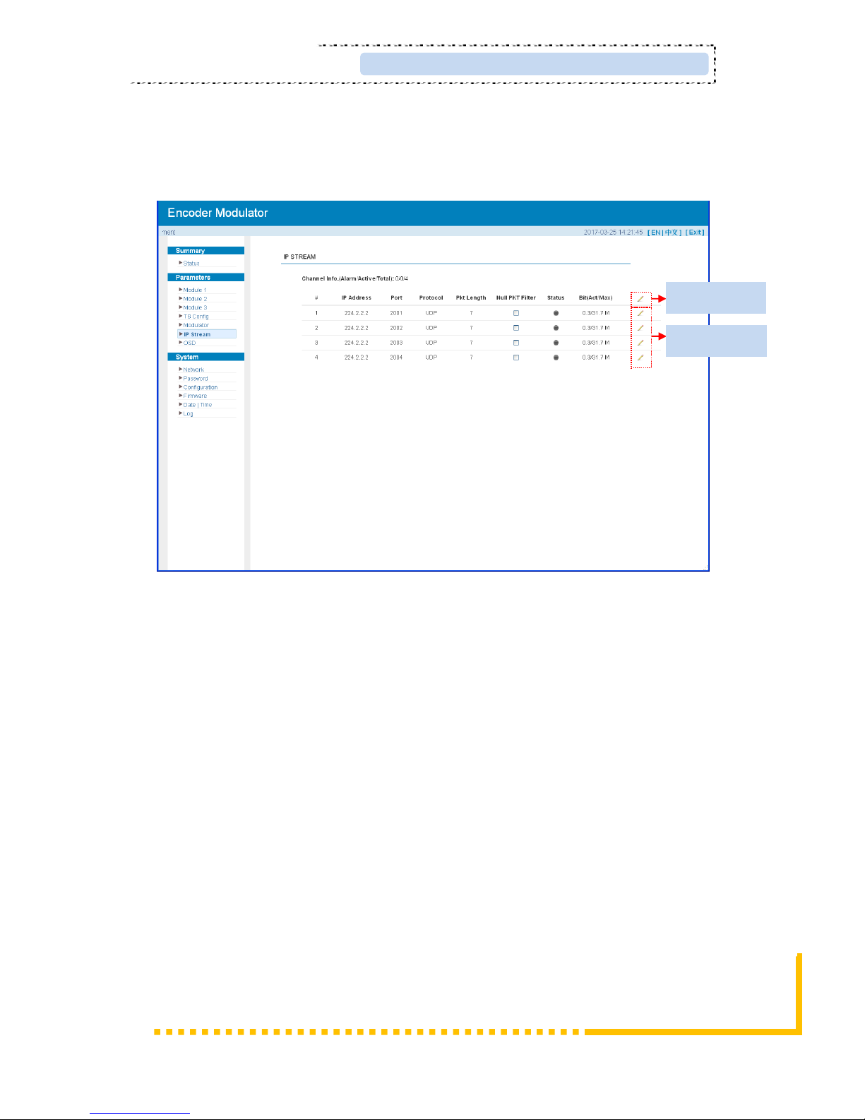
Parameters → Modulator:
From the menu on left side of the webpage, clicking “Modulator”, it will display the
Modulator Configuration screen as Figure-8. Here user can set modulation parameters.
Figure-8
Page 19
ClearView Corp. Ltd. Page 15 / 29
KR423I Encoder Modualtor User Manual
Parameters → IP Stream:
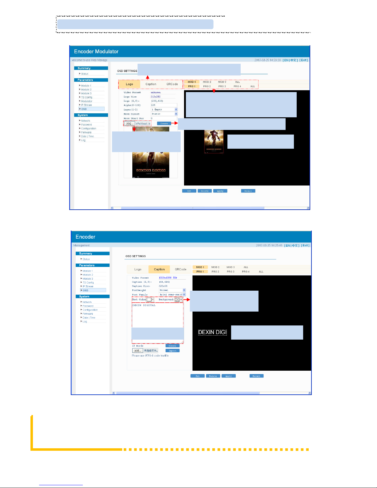
KR423Isupports TS to output in IP (4*MPTS) format through the DATA1 port.
Click ‘IP Stream’, it will display the interface where to set IP out parameters (Figure-9).
Figure-9
Parameters→ OSD:
Click ‘OSD’, it will display the interface where to configuration the OSD parameters
(Figure-10)
Quickly Config
Channel Config
Page 20
Page 16 / 29 ClearView Corp. Ltd.
KR423I Encoder Modulator User Manual
Figure-10
Figure-11
Enter your text here
Select the text color and
background color
Put your caption anywhere
Select to configure logo, caption or QRcode
Browse and select the Logo
which has been created
Put your logo everywhere
Click here to comfirm the LOGO you selected
Select program1/2/3/4 of Module1/2/3 to apply
the logo insertion, or you can select all to apply
all programs and all modules
Page 21
ClearView Corp. Ltd. Page 17 / 29
KR423I Encoder Modualtor User Manual
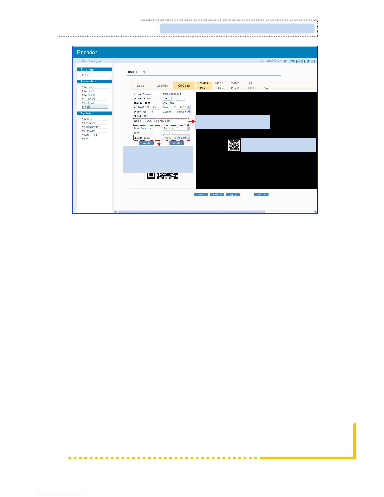
Figure-12
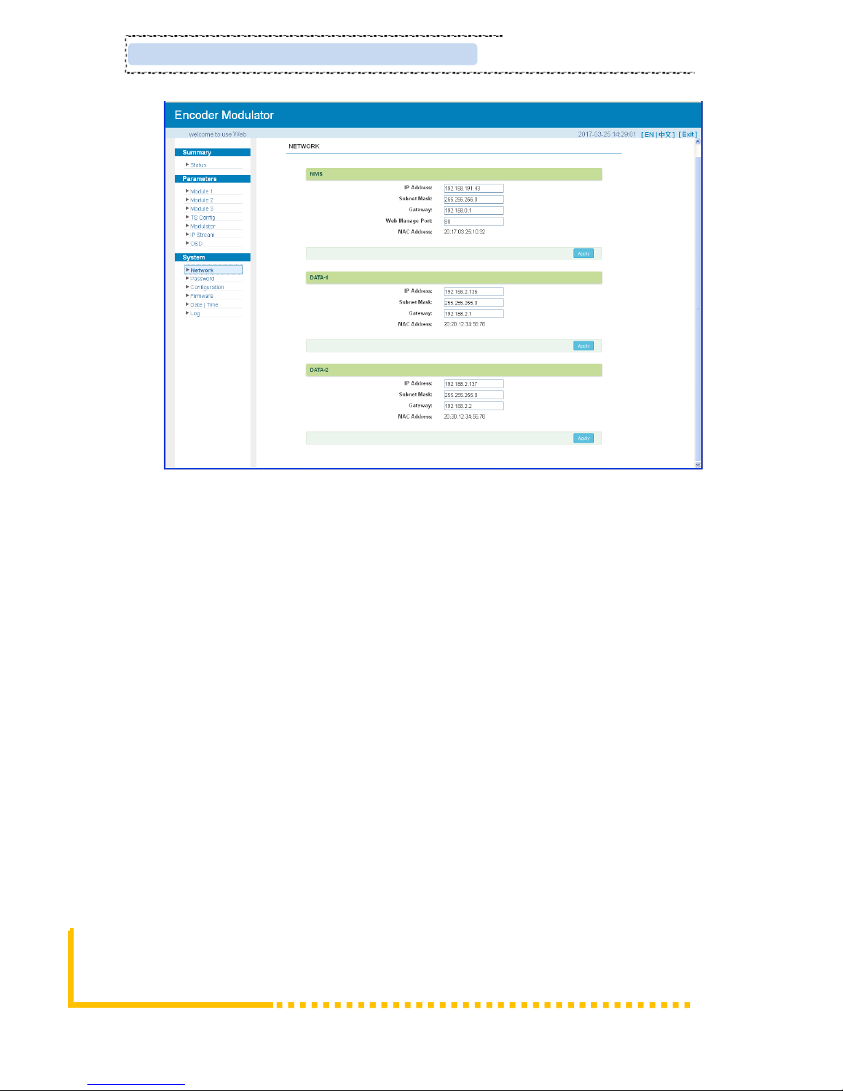
System → Network:
Click ‘Network’, it will display the interface as Figure-13 where to set network parameters.
Put your QRcode everywhere
Browse and select the
QRcode which has been
created
Put your QRcode URL here
Page 22
Page 18 / 29 ClearView Corp. Ltd.
KR423I Encoder Modulator User Manual
Figure-13
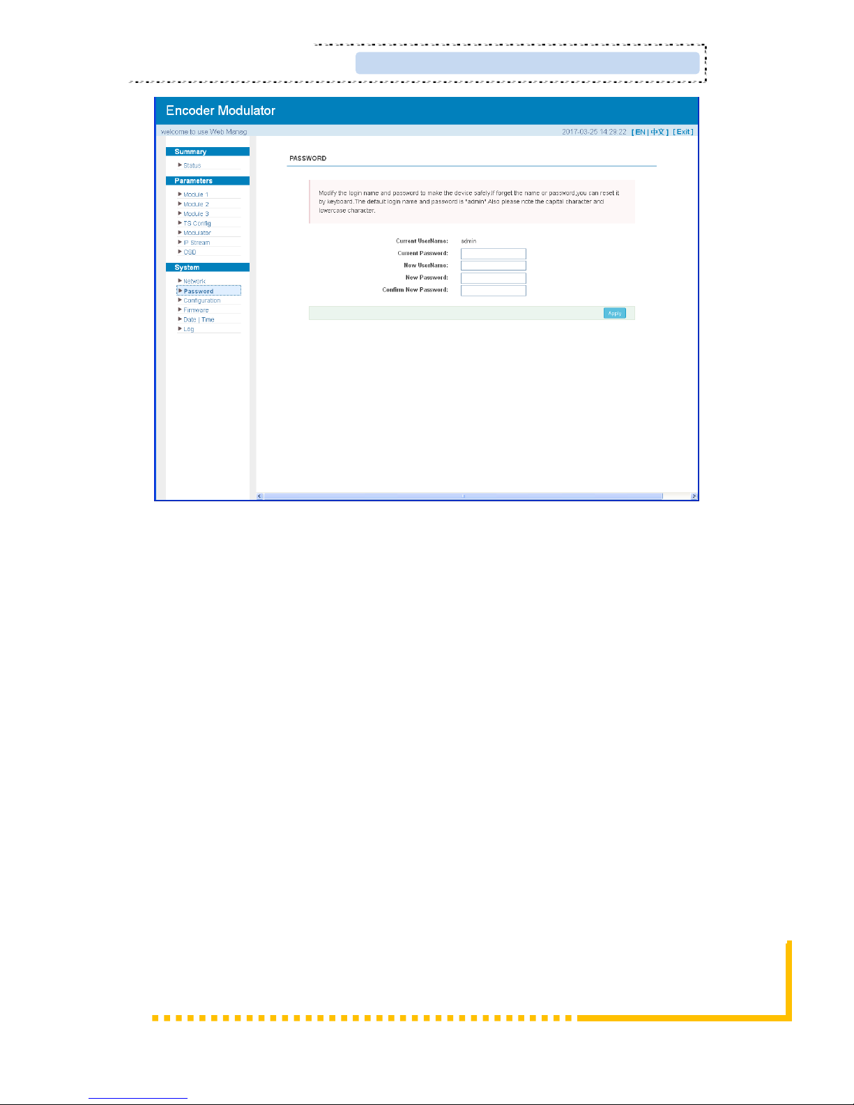
System → password
From the menu on left side of the webpage, clicking “Password”, it will display the
screen as Figure-14 where to set the login account and password for the web NMS.
Page 23
ClearView Corp. Ltd. Page 19 / 29
KR423I Encoder Modualtor User Manual
Figure-14
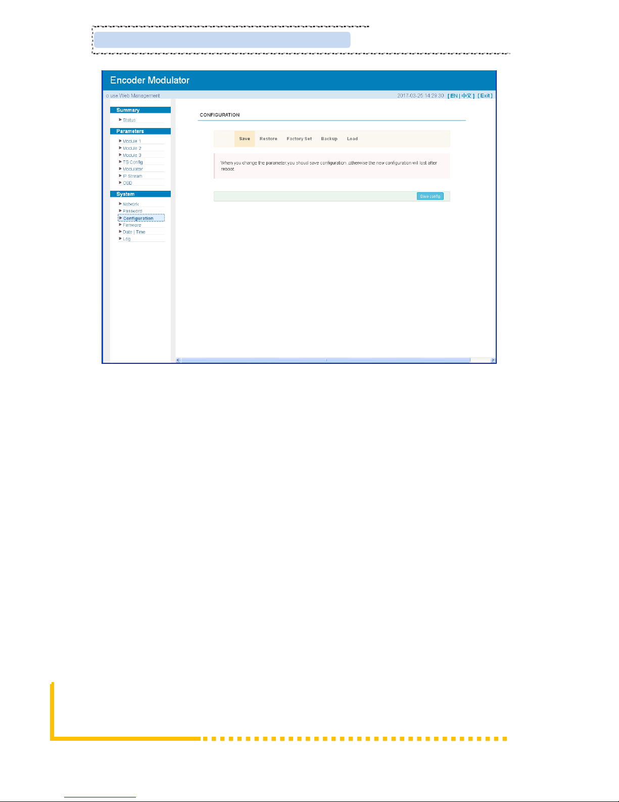
System → Configuration:
From the menu on left side of the webpage, clicking “Configuration”, it will display the
screen as Figure-15 where to save/ restore/factory setting/ backup/ load your
configurations.
Page 24
Page 20 / 29 ClearView Corp. Ltd.
KR423I Encoder Modulator User Manual
Figure-15
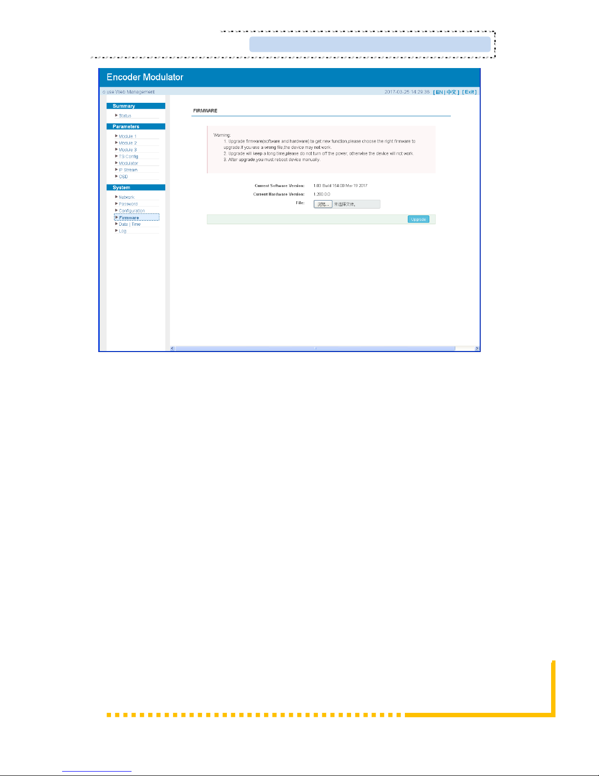
System → Firmware:
From the menu on left side of the webpage, clicking “Firmware”, it will display the
screen as Figure-16 where to update firmware for the modulator.
Page 25
ClearView Corp. Ltd. Page 21 / 29
KR423I Encoder Modualtor User Manual
Figure-16
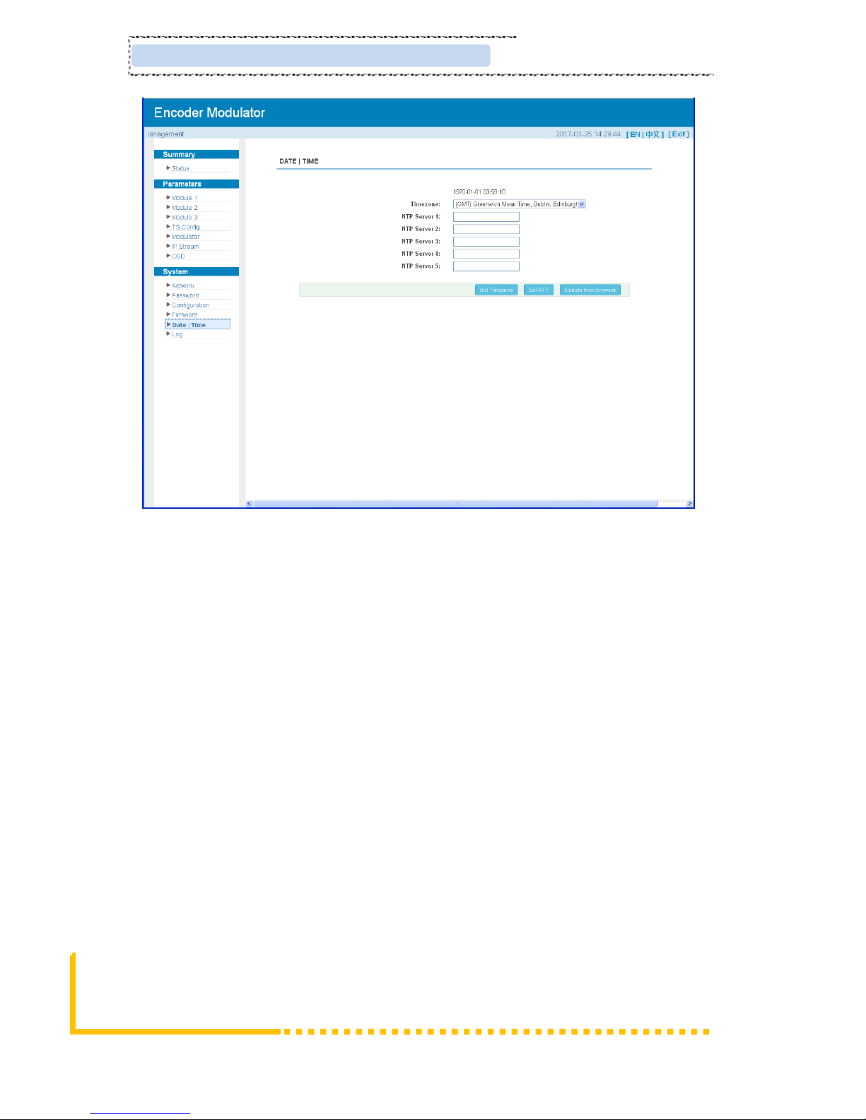
System→ Date/Time:
From the menu on left side of the webpage, clicking “Date/Time”, it will display the
screen as Figure-17 where to set date and time for the device.
Page 26
Page 22 / 29 ClearView Corp. Ltd.
KR423I Encoder Modulator User Manual
Figure-17
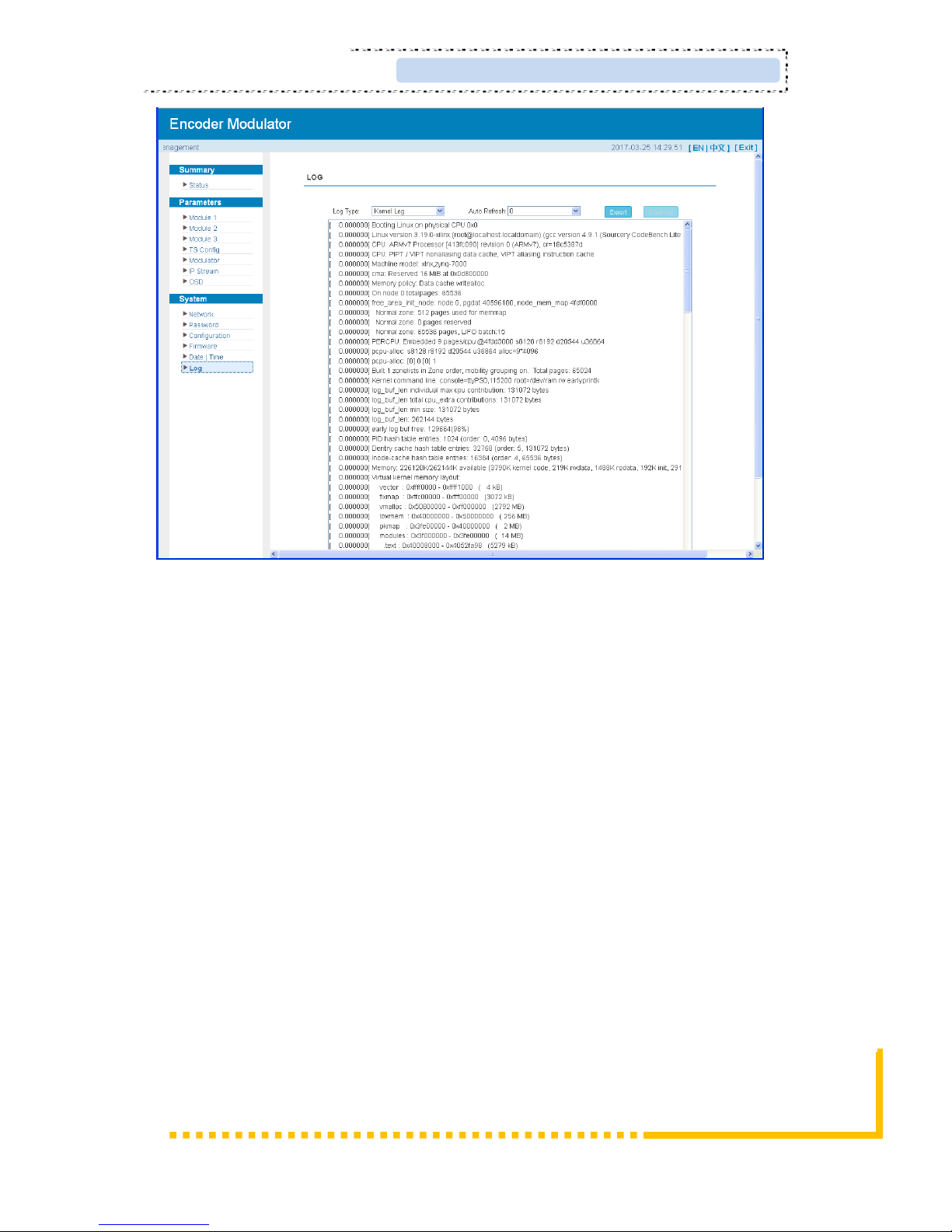
System→ Log:
From the menu on left side of the webpage, clicking “Log”, it will display the log
interface as Figure-18 where to check or export the Kernel/System log.
Page 27
ClearView Corp. Ltd. Page 23 / 29
KR423I Encoder Modualtor User Manual
Figure-18
Page 28

Page 24 / 29 ClearView Corp. Ltd.
KR423I Encoder Modulator User Manual
Chapter 4 Troubleshooting
CLEARVIEW’s ISO9001 quality assurance system has been approved by CQC
organization. For guarantee the products’ quality, reliability and stability. All
CLEARVIEW products have been passed the testing and inspection before ship out
factory. The testing and inspection scheme already covers all the Optical, Electronic
and Mechanical criteria which have been published by CLEARVIEW. To prevent
potential hazard, please strictly follow the operation conditions.
Prevention Measure
➢ Installing the device at the place in which environment temperature between 0 to
45 °C
➢ Making sure good ventilation for the heat-sink on the rear panel and other heat-sink
bores if necessary
➢ Checking the input AC within the power supply working range and the connection
is correct before switching on device
➢ Checking the RF output level varies within tolerant range if it is necessary
➢ Checking all signal cables have been properly connected
➢ Frequently switching on/off device is prohibited; the interval between every
switching on/off must greater than 10 seconds.
Conditions need to unplug power cord
➢ Power cord or socket damaged.
➢ Any liquid flowed into device.
➢ Any stuff causes circuit short
➢ Device in damp environment
➢ Device was suffered from physical damage
➢ Longtime idle.
➢ After switching on and restoring to factory setting, device still cannot work properly.
➢ Maintenance needed
Page 29

ClearView Corp. Ltd. Page 25 / 29
KR423I Encoder Modualtor User Manual
Chapter 5 Packing List
KR423IEncoder Modulator 1 pcs
User Manual 1 pcs
HDMI Cables 4 pcs
Power Cord 1pcs
 Loading...