

Page 1

Clearview HD IR Waterproof Network Dome Camera
Quick Start Guide
Version 1.2.0
Page 2

i
Welcome
Thank you for purchasing our network camera!
This quick start guide is designed to be a reference tool for your system.
Please keep this start guide well for future reference.
Please open the accessory bag to check the items one by one in accordance with the list below.
Contact your local retailer ASAP if something is missing or damaged in the bag.
Before your operation please read the following instructions carefully.
1᧪᧪Electrical safety
All installation and operation here should conform to your local electrical safety codes.
The power shall conform to the requirement in the SELV (Safety Extra Low Voltage) and the Limited
power source is rated 12V or 24V AC DC in the IEC60950-1. (Refer to general introduction)
Please note: Do not connect two power supplying sources to the device at the same time; it may
result in device damage!
We assume no liability or responsibility for all the fires or electrical shock caused by improper handling
or installation.
We are not liable for any problems caused by unauthorized modification or attempted repair.
2᧪Transportation security
Heavy stress, violent vibration or water splash are not allowed during transportation, storage and
installation.
3᧪Installation
Do not apply power to the camera before completing installation.
Please install the proper power cut-off device during the installation connection.
Always follow the instruction guide the manufacturer recommended.
4᧪Qualified engineers needed
All the examination and repair work should be done by the qualified service engineers.
We are not liable for any problems caused by unauthorized modifications or attempted repair.
5᧪Environment
This series network camera should be installed in a cool, dry place away from direct sunlight,
inflammable, explosive substances and etc.
Please keep it away from the electromagnetic radiation object and environment.
Please make sure the CCD (CMOS) component is out of the radiation of the laser beam device.
Otherwise it may result in CCD (CMOS) optical component damage.
Please keep the sound ventilation.
Do not allow the water and other liquid falling into the camera.
Page 3
ii
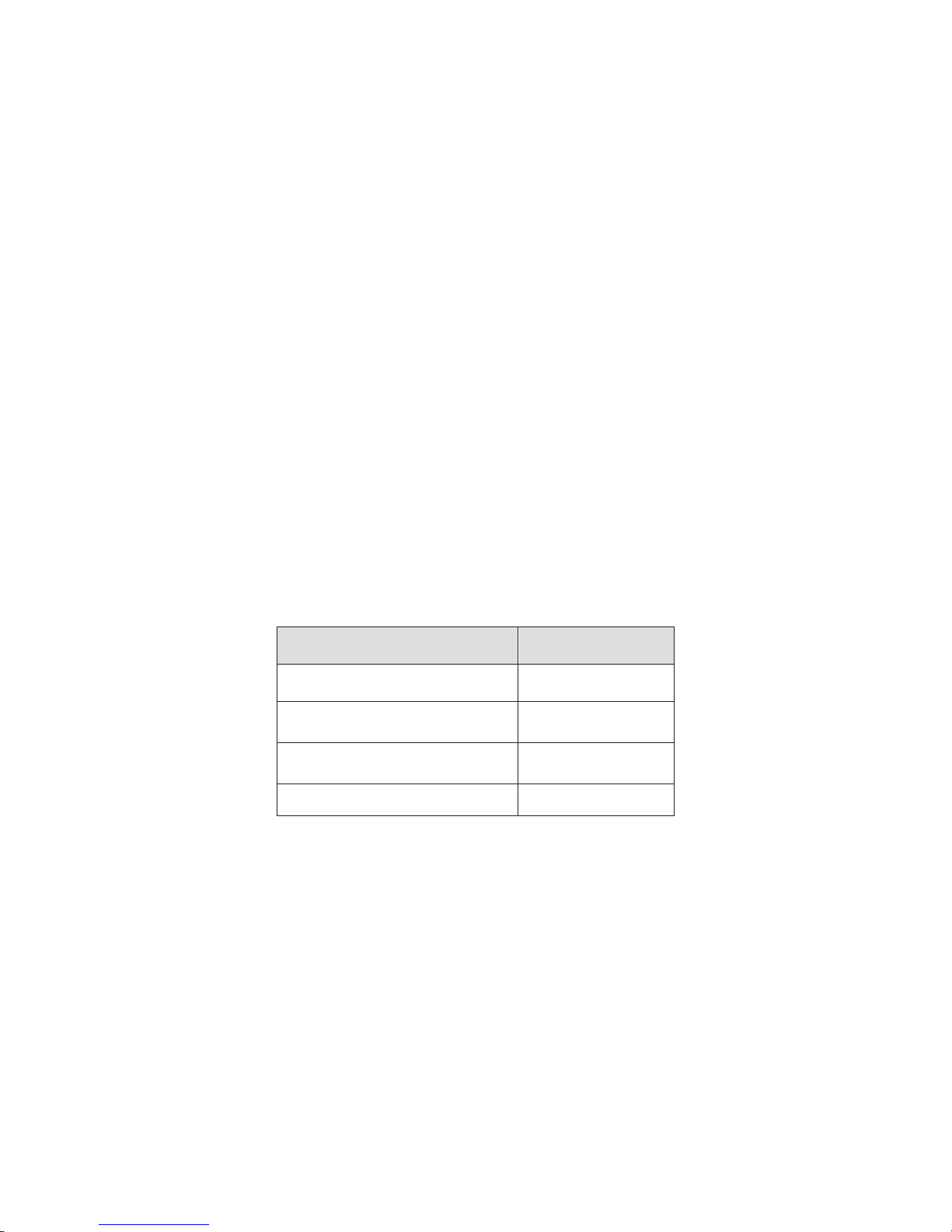
Accessory Name
Amount
N
1
Quick Start Guide
1
Installation
1
CD
1
Thunder-proof device is recommended to be adopted to better prevent thunder.
The grounding studs of the product are recommended to be grounded to further enhance the reliability
of the camera.
6. Daily Maintenance
Please shut down the device and then unplug the power cable before you begin daily maintenance
work.
Do not touch the CCD (CMOS) optic component. You can use the blower to clean the dust on the lens
surface.
Always use the dry soft cloth to clean the device. If there is too much dust, please use the water to
dilute the mild detergent first and then use it to clean the device. Finally use the dry cloth to clean the
device.
Please put the dustproof cap to protect the CCD (CMOS) component when you do not use the camera.
Dome enclosure is the optical component, do not touch the enclosure when you are installing the
device or clean the enclosure when you are doing maintenance work. Please use professional optical
clean method to clean the enclosure. Improper enclosure clean method (such as use cloth) may result
in poor IR effect of camera with IR function.
7. Accessories
Be sure to use all the accessories recommended by manufacturer.
Before installation, please open the package and check all the components are included.
Contact your local retailer ASAP if something is broken in your package.
etwork Camera Unit
Accessories Bag
Page 4

iii
Table of Contents
6WUXFWXUH ................................................................................................................................. 1
&RPSRQHQWV ............................................................................................................. 1
)UDPHZRUNDQG'LPHQVLRQ ..................................................................................... 1
'HYLFH,QVWDOODWLRQ ................................................................................................................. 3
,QVWDOODWLRQ6WHSV ...................................................................................................... 3
5HVWRUH)DFWRU\'HIDXOW6HWXS,QWURGXFWLRQ .......................................................... 5
3 Quick Configuration Tool ...................................................................................................... 6
3.1 Overview ................................................................................................................... 6
3.2 Operation .................................................................................................................. 6
4 Web Operation ....................................................................................................................... 8
4.1 Network Connection................................................................................................. 8
4.2 Login and Main Interface ......................................................................................... 8
$SSHQGL[7R[LFRU+D]DUGRXV0DWHULDOVRU(OHPHQWV ............................................................. 11
Page 5
1
6WUXFWXUH
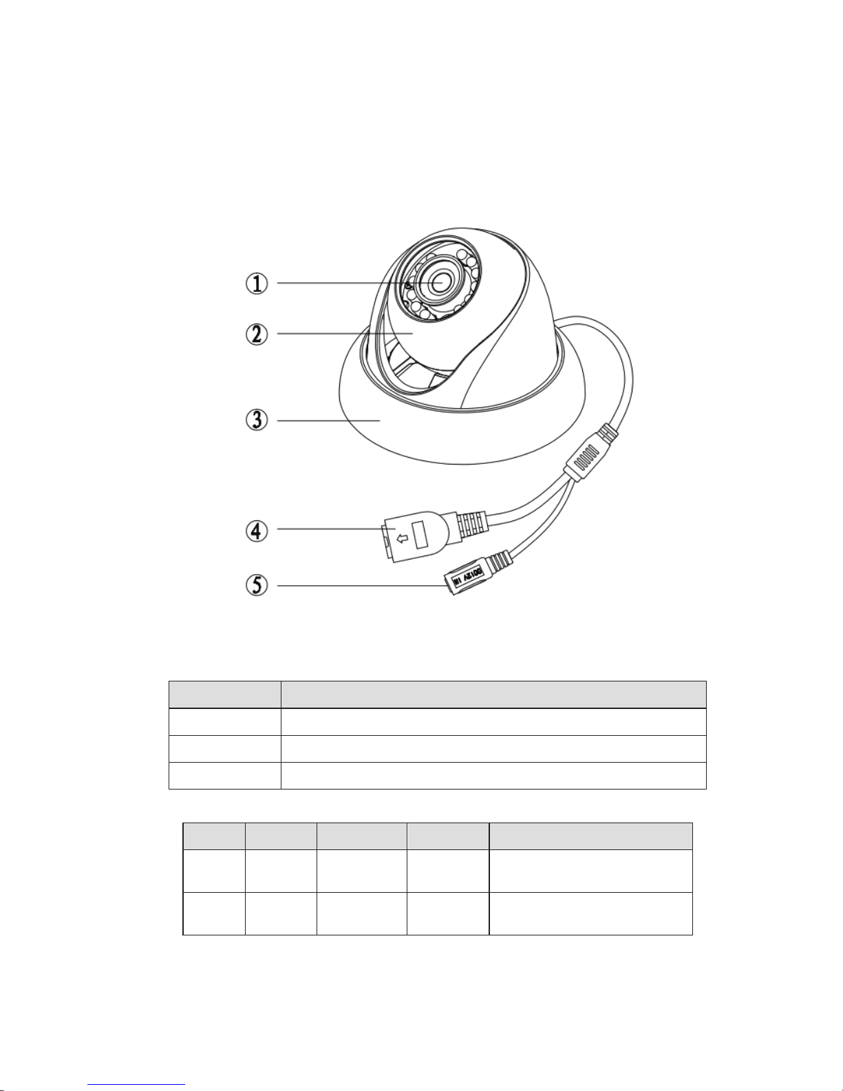
&RPSRQHQWV
No. Port Name
Connector
Note
4
LAN
Network
port
Ethernet
To connect to standard
Ethernet.
5
DC12V
DC 12V
power
To connect to
power
supply.
)UDPHZRUNDQG'LPHQVLRQ
Component
Component Name
Component 1
Device lens
Component 2
Dome body
Component 3
Dome enclosure
You can refer to the following figure for multiple-function combination cable information. See Figure
1-1
.
Figure 1-1 Multiple-function combination cable
Please refer to the following sheet for detailed information.
DC12V
Page 6
2
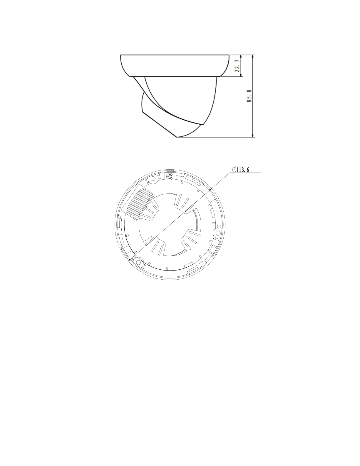
Please refer to the following two figures for dimension information. The unit is mm. See Figure 1-2 and
Figure 1-3.
Figure 1-2 Dimension illustration 1
Figure 1-3 Dimension illustration 2
Page 7
3
'HYLFH,QVWDOODWLRQ
,QVWDOODWLRQ6WHSV
Important
Before the installation, please make sure the installation environments can at least support 3x weight
of the camera.
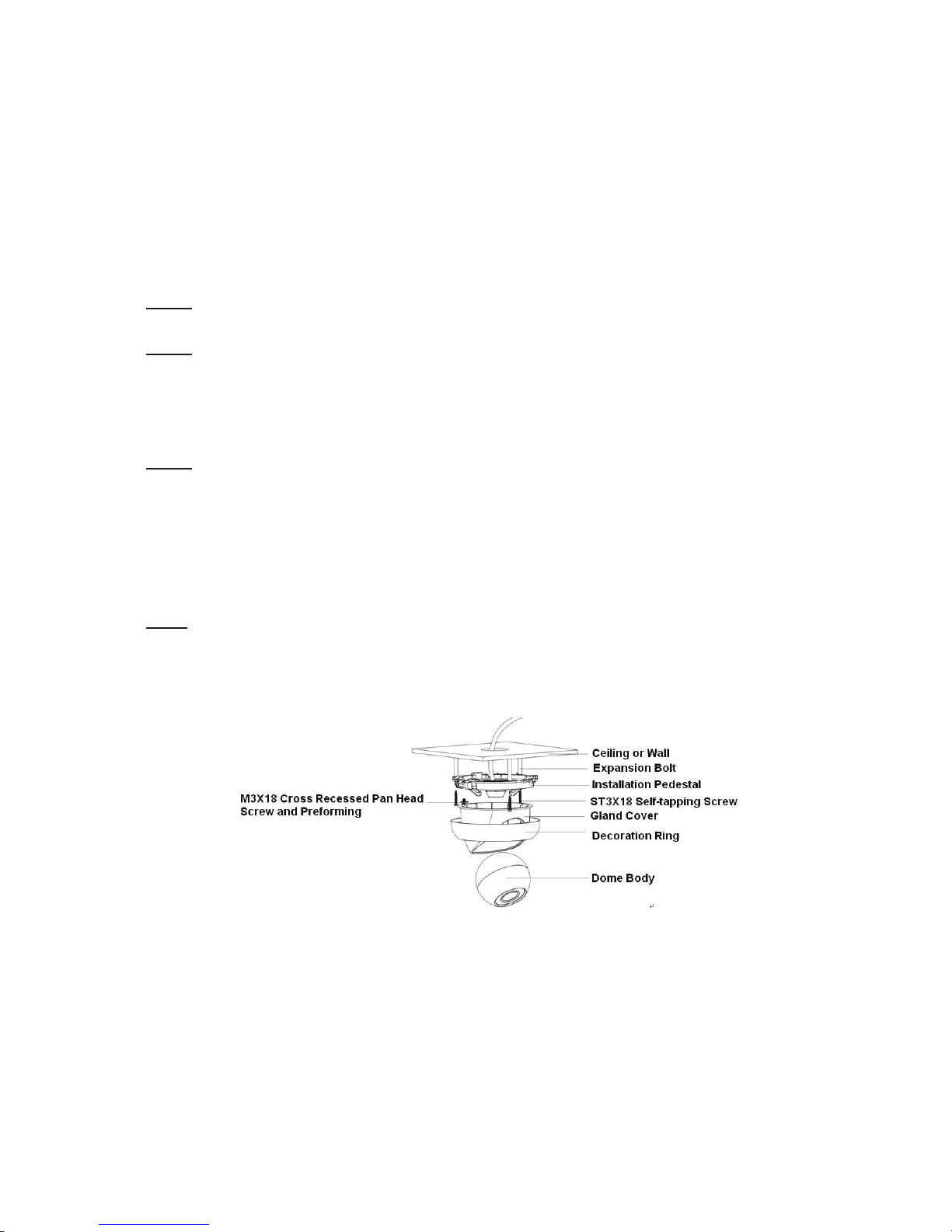
Please follow the steps listed below to install the device. Please refer to Figure 2-1 for reference.
Step 1
Turn clockwise to remove the decoration ring from the snap joints.
Step 2
Please take the installation position map in the accessories bag, and then paste it on the ceiling or the
wall according to your monitor area requirements. Draw and then dig three plastic expansion bolts
holes in the installation surface and then insert three expansion bolts in the holes. Secure these three
bolts firmly. Please draw the cable out from the cable exit when you install the device.
Step 3
Adjust the device installation pedestal to the proper position and then line up the three screw holes in
the device pedestal to the three plastic expansion bolt holes in the installation position. Put the three
self-tapping screws in the three plastic expansion bolts firmly. Loosen the M3X8 cross recessed pan
head slot screw of the pedestal to unfasten the preforming. (Do not remove, loosen a little bit will be
OK.). Adjust the lens to the proper monitor angle and then use the original preforming to turn the M3X8
cross recessed pan head slot screw back.
Step4
Line up the three spigots of the decoration ring to the jags from the bottom to the top and then turn
clockwise until you hear a clear sound ”KA”. Now the installation is complete.
Important
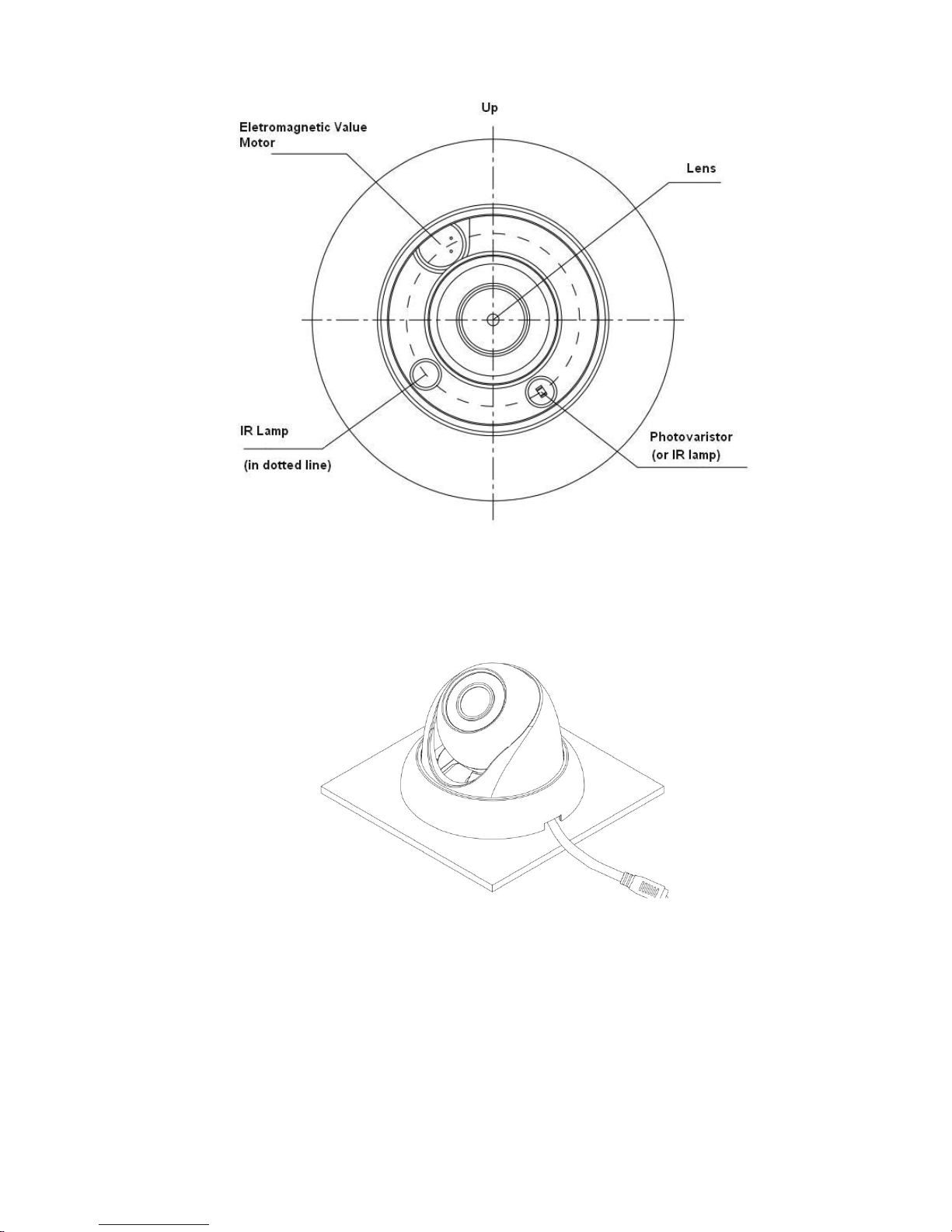
Please pay attention to the dome camera direction when you are installing. Please refer to the
following figure for detailed information. See Figure 2-2.
Figure 2-1 Device installation illustration 1
Page 8
4
Figure 2-2 Device installation illustration 2
Note
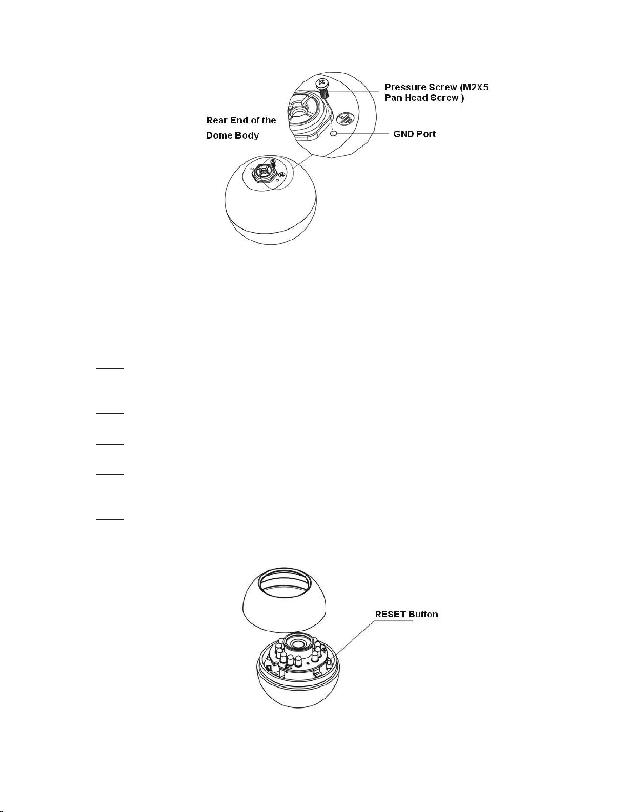
This series product supports two cable exits. One is from the bottom and the other is from the side.
Please refer to the following figure for cable exit from the side information.
Figure 2-3 Device installation illustration 3
Please earth the GND port of the device to enhance the device reliability. The GND port is near the
cable exit port on the rear of the dome. The GND screw uses the M2X5 pan screw.
Page 9
5
5HVWRUH)DFWRU\'HIDXOW6HWXS,QWURGXFWLRQ
Figure 2-4 Device installation illustration 4
Important
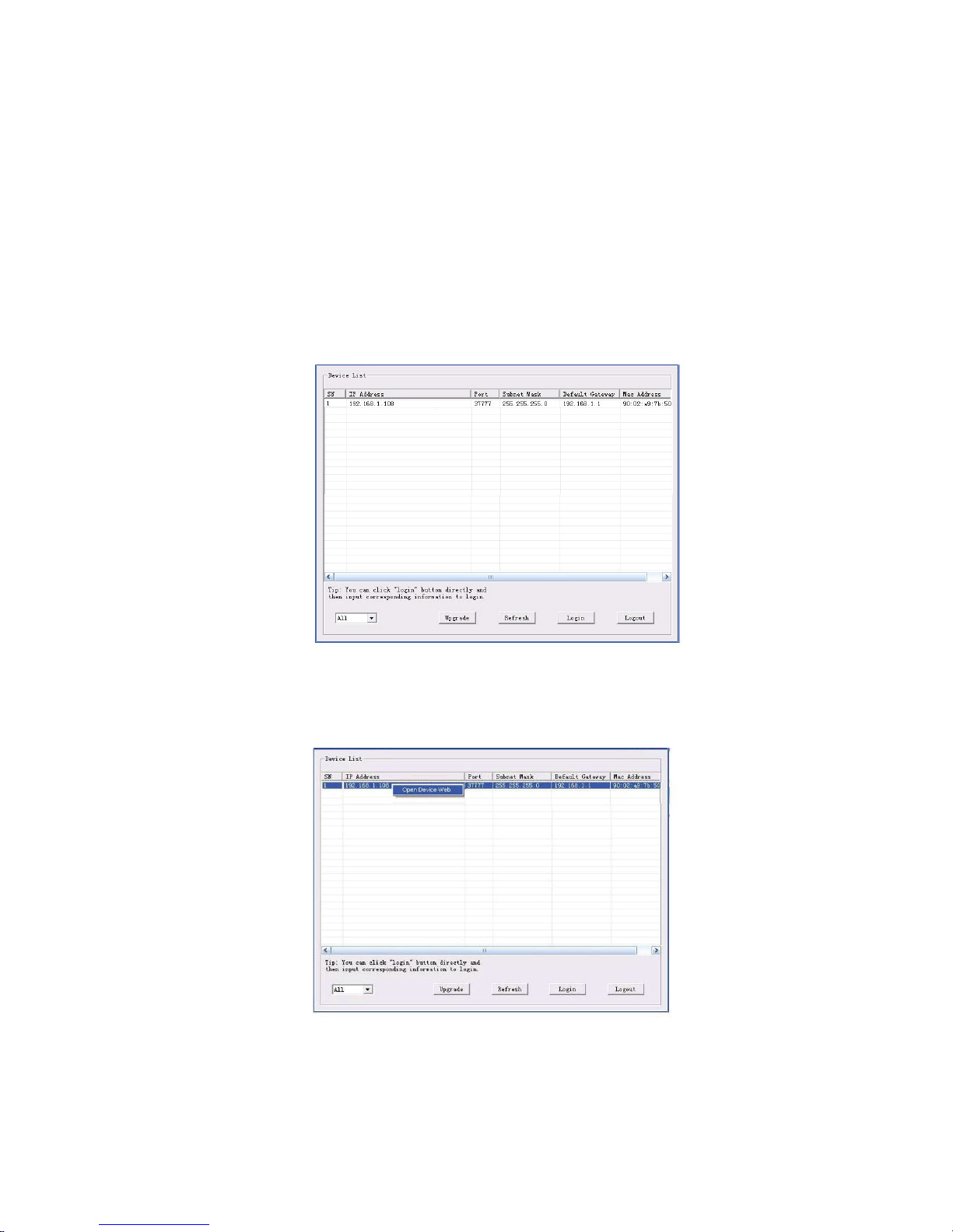
Please use RESET button when device is running.
Step1
Please refer to step1 and step2 in chapter 2.1to loose the dome body. Push a little bit; you can take
the dome body from the gland cover.
Step2
Take the dome body out and then turn the top cover hard to remove.
Step3
Slightly press the RESET button to complete the reset function. See Figure 2-5.
Step4
Turn the top cover back to the original position. Please make sure it reaches the original position,
otherwise it may result in water leakage!
Step5
Put the dome back to the gland cover. Please refer to step4 in chapter 2.1 to install the decoration ring
back.
Figure 2-5 Reset
Page 10
6
3 Quick Configuration Tool
3.1 Overview
Quick configuration tool can search current IP address, modify IP address. At the same time, you can
use it to upgrade the device.
Please note the tool only applies to the IP addresses in the same segment.
3.2 Operation
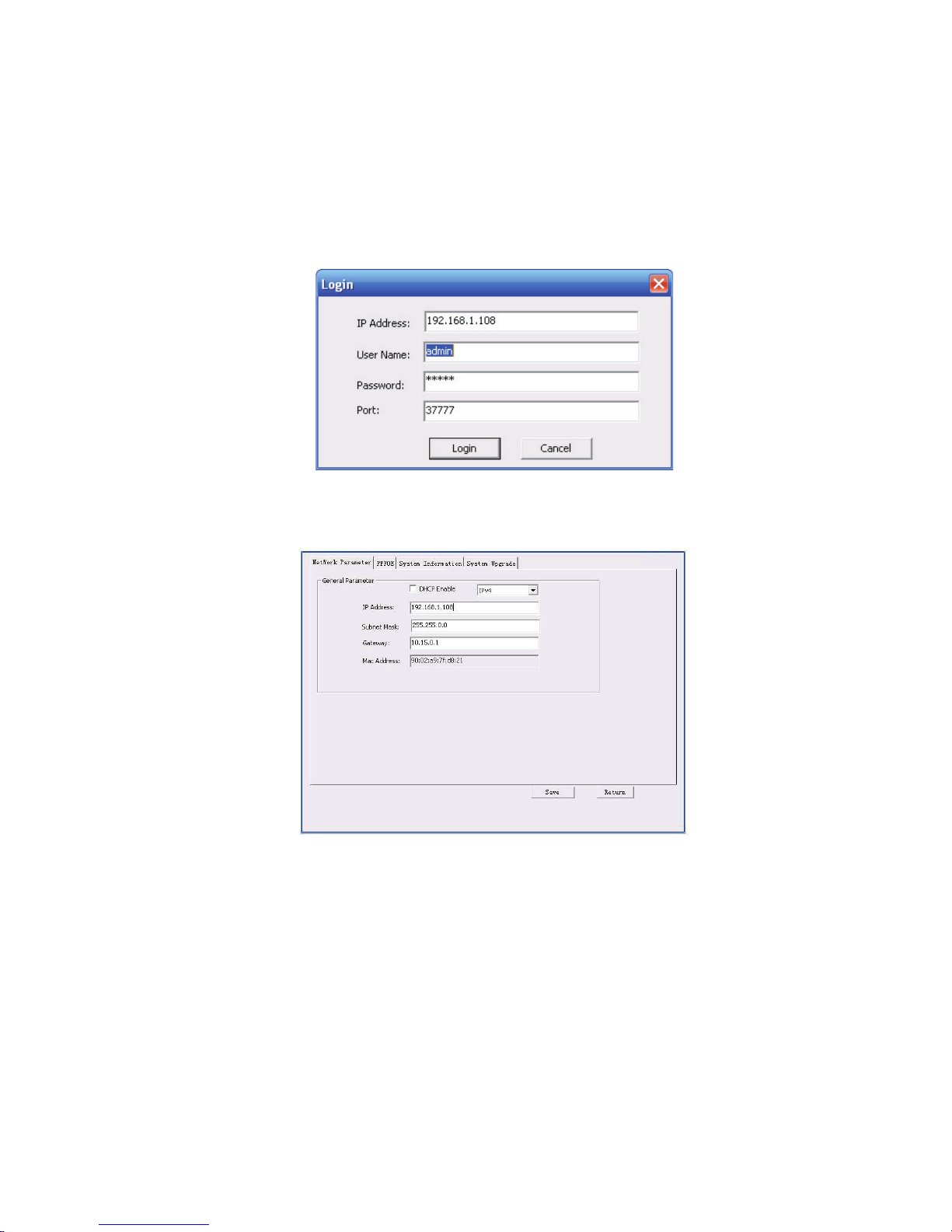
Double click the “ConfigTools.exe” icon, you can see an interface is shown as in Figure 3-1.
In the device list interface, you can view device IP address, port number, subnet mask, default
gateway, MAC address and etc.
Figure 3-1 Search interface
Select one IP address and then right click mouse, you can see an interface is shown as in Figure 3-2.
Select the “Open Device Web” item; you can go to the corresponding web login interface.
Figure 3-2 Search interface 2
If you want to modify the device IP address without logging in the device web interface, you can go to
the configuration tool main interface to set.
Page 11
7
In the configuration tool search interface (Figure 3-1), please select a device IP address and then
double click it to open the login interface. Or you can select an IP address and then click the Login
button to go to the login interface. See Figure 3-3.
In Figure 3-3, you can view device IP address, user name, password and port. Please modify the
corresponding information to login.
Please note the port information here shall be identical with the port value you set in TCP port in Web
Network interface. Otherwise, you cannot login the device.
If you are using device background upgrade port 3800 to login, other setups are all invalid.
Figure 3-3 Login prompt
After you logged in, the configuration tool main interface is shown as below. See Figure 3-4.
Figure 3-4 Main interface
For detailed information and operation instruction of the quick configuration tool, please refer
to the Quick Configuration Tool User’s Manual included in the resources CD.
Page 12
8
Input your IP
address here
4 Web Operation
This series network camera products support the Web access and management via PC.
Web includes several modules: Monitor channel preview, system configuration, alarm and etc.
4.1 Network Connection
Please follow the steps listed below for network connection.
z Make sure the network camera has connected to the network properly.
z Please set the IP address, subnet mask and gateway of the PC and the network camera
respectively. Network camera default IP address is 192.168.1.108. Subnet mask is 255.255.255.0.
Gateway is 192.168.1.1
z Use order ping ***.***.***.***(* network camera address) to check connection is OK or not.
4.2 Login and Main Interface
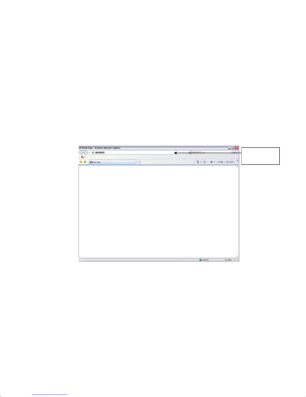
Open IE and input network camera address in the address bar. See Figure 4- 1.
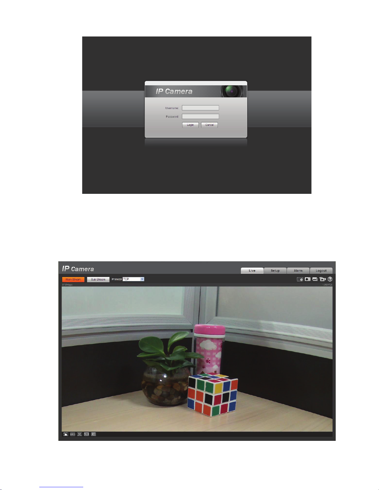
The login interface is shown as below. See Figure 4- 2.
Please input your user name and password.
Default factory name is admin and password is admin.
Note: For security reasons, please modify your password after you first login.
Figure 4- 1 IP address
Page 13
9
Figure 4- 2 Web login
If it is your first time to log in, system pops up warning information to ask you whether install web plug-
in or not after you logged in for one minute. For detailed plug-in installation, please refer to the Web
Operation Manual included in the resource CD.
After you logged in, you can see the main window. See Figure 4- 3.
Figure 4- 3 Web monitoring window
Page 14

10
Please refer to the Web Operation Manual included in the resource CD for detailed operation
instruction.
Page 15
11
$SSHQGL[7R[LFRU+D]DUGRXV0DWHULDOVRU(OHPHQWV
Component
Cr VI
Circuit Board
Component
Case
Wire and Cable
Packing
Components
Accessories
○ ○ ○ ○ ○
○
$
Toxic or Hazardous Materials or Elements
Name
Device
O: Indicates that the concentration of the hazardous substance in all homogeneous materials in the
parts is below the relevant threshold of the SJ/T11363-2006 standard.
X: Indicates that the concentration of the hazardous substance of at least one of all homogeneous
materials in the parts is above the relevant threshold of the SJ/T11363-2006 standard. During the
environmental-friendly use period (EFUP) period, the toxic or hazardous substance or elements
contained in products will not leak or mutate so that the use of these (substances or elements) will not
result in any severe environmental pollution, any bodily injury or damage to any assets. The consumer
is not authorized to process such kind of substances or elements, please return to the corresponding
local authorities to process according to your local government statutes.
Note:
Pb Hg Cd
○ ○ ○ ○ ○ ○
○
○
○ ○ ○ ○ ○ ○
○ ○ ○ ○ ○
○ ○ ○ ○ ○
PBB
PBDE
z This quick start guide is for reference only. Slight difference may be found in user interface.
z All the designs and software here are subject to change without prior written notice.
z All trademarks and registered trademarks mentioned are the properties of their respective
owners.
z If there is any uncertainty or controversy, please refer to the final explanation of us.
z Please visit our website or contact your local service engineer for more information.
Page 16

Clearview HD IR Waterproof Network Dome Camera
User’s Manual
Version 4.0.1
Page 17

i
Welcome
Thank you for purchasing our Network camera!
This user’s manual is designed to be a reference tool for your system.
Please read the following safeguard and warnings carefully before you use this series product!
Please keep this user’s manual well for future reference!
Page 18

ii
Important Safeguards and Warnings
1᧪᧪Electrical safety
All installation and operation here should conform to your local electrical safety codes.
The power shall conform to the requirement in the SELV (Safety Extra Low Voltage) and the Limited
power source is rated 12V or 24V AC DC in the IEC60950-1. (Refer to general introduction)
Please note: Do not connect two power supplying sources to the device at the same time; it may
result in device damage!
We assume no liability or responsibility for all the fires or electrical shock caused by improper handling
or installation.
We are not liable for any problems caused by unauthorized modification or attempted repair.
2᧪Transportation security
Heavy stress, violent vibration or water splash are not allowed during transportation, storage and
installation.
3᧪Installation
Do not apply power to the camera before completing installation.
Please install the proper power cut-off device during the installation connection.
Always follow the instruction guide the manufacturer recommended.
4᧪Qualified engineers needed
All the examination and repair work should be done by the qualified service engineers.
We are not liable for any problems caused by unauthorized modifications or attempted repair.
5᧪Environment
This series network camera should be installed in a cool, dry place away from direct sunlight,
inflammable, explosive substances and etc.
Please keep it away from the electromagnetic radiation object and environment.
Please make sure the CCD (CMOS) component is out of the radiation of the laser beam device.
Otherwise it may result in CCD (CMOS) optical component damage.
Please keep the sound ventilation.
Do not allow the water and other liquid falling into the camera.
Thunder-proof device is recommended to be adopted to better prevent thunder.
The grounding studs of the product are recommended to be grounded to further enhance the reliability
of the camera.
6. Daily Maintenance
Please shut down the device and then unplug the power cable before you begin daily maintenance
work.
Page 19
iii
Accessory Name
Amount
N
1
Quick Start Guide
1
Installation
1
CD
1
Do not touch the CCD (CMOS) optic component. You can use the blower to clean the dust on the lens
surface.
Always use the dry soft cloth to clean the device. If there is too much dust, please use the water to
dilute the mild detergent first and then use it to clean the device. Finally use the dry cloth to clean the
device.
Please put the dustproof cap to protect the CCD (CMOS) component when you do not use the camera.
Dome enclosure is the optical component, do not touch the enclosure when you are installing the
device or clean the enclosure when you are doing maintenance work. Please use professional optical
clean method to clean the enclosure. Improper enclosure clean method (such as use cloth) may result
in poor IR effect of camera with IR function.
7. Accessories
Be sure to use all the accessories recommended by manufacturer.
Before installation, please open the package and check all the components are included.
Contact your local retailer ASAP if something is broken in your package.
etwork Camera Unit
Accessories Bag
Page 20

iv
Table of Contents
*HQHUDO,QWURGXFWLRQ .............................................................................................................. 1
2YHUYLHZ ................................................................................................................... 1
)HDWXUHV .................................................................................................................... 1
6SHFLILFDWLRQV ........................................................................................................... 2
)DFWRU\'HIDXOW6HWXS .............................................................................................. 3
6WUXFWXUH ................................................................................................................................. 9
&RPSRQHQWV ............................................................................................................. 9
)UDPHZRUNDQG'LPHQVLRQ ..................................................................................... 9
'HYLFH,QVWDOODWLRQ ............................................................................................................... 11
,QVWDOODWLRQ6WHSV .................................................................................................... 11
5HVWRUH)DFWRU\'HIDXOW6HWXS,QWURGXFWLRQ ........................................................ 13
4 Quick Configuration Tool .................................................................................................... 14
4.1 Overview ................................................................................................................. 14
4.2 Operation ................................................................................................................ 14
5 Web Operation ..................................................................................................................... 16
5.1 Network Connection............................................................................................... 16
5.2 Login and Main Interface ....................................................................................... 16
)$4 ....................................................................................................................................... 19
$SSHQGL[7R[LFRU+D]DUGRXV0DWHULDOVRU(OHPHQWV ............................................................. 20
Page 21

1
*HQHUDO,QWURGXFWLRQ
2YHUYLHZ
)HDWXUHV
Management
z Different user rights for each group, one user belongs to one group.
Function
z Support central server backup function in accordance with your configuration
end
z Support network storage function such as FTP.
Network
Monitor
z Network camera supports one-channel video data transmit to network
(network bandwidth
, TCP, UDP,
z Support web access.
Network
Management
z Realize network camera configuration and management via Ethernet.
Support device management via web or client-end.
Power
z External power adapter DC 12V.
Warning
ʽ
D
same time; it may result in device damage!
Assistant
Function
z Log function
time display.
shutter and gain setup.
compensation
z The enclosure conforms to the IP 66 protection. Has the waterproof function.
This series network camera integrates the traditional camera and network video technology. It adopts
video data collection, transmission together. It can connect to the network directly without any auxiliary
device.
This series network camera uses standard H.264 video compression technology, which maximally
guarantees the video quality.
It supports the IR night vision function. In the night environments, the device can use the IR light to
highlight the object which is suitable for the surveillance function in the low illumination environments.
The waterproof design conforms to the IP 66 level. It has the sound waterproof function suitable for
use in the outdoor environments.
It can be used alone or used in a network area. When it is used lonely, you can connect it to the
network and then use a network client-end. Due to its multiple functions and various uses, this series
network camera is widely used in many environments such office, bank, road monitor and etc.
User
Storage
z The user right shall not exceed the group right.
and setup in alarm or schedule setting
z Support record via Web and the recorded file are storage in the client-
PC.
terminal and then decode. Delaying time is within 270ms
support needed)
z Max supports 20 connections.
z Adopt the following video transmission protocol: HTTP
MULTICAST, RTP/RTCP, RTSP and etc.
z
z Support PoE.
o not connect these two power supplying sources to the device at the
z Support system resource information and running status real-
z Day/Night mode auto switch.
z Support picture parameter setup such as electronic
z Support motion detect.
z Backlight compensation: screen auto split to realize backlight
z Support video watermark function to avoid vicious video modification.
z Built-in IR light. Support IR night vision.
to adjust the bright.
Page 22
2
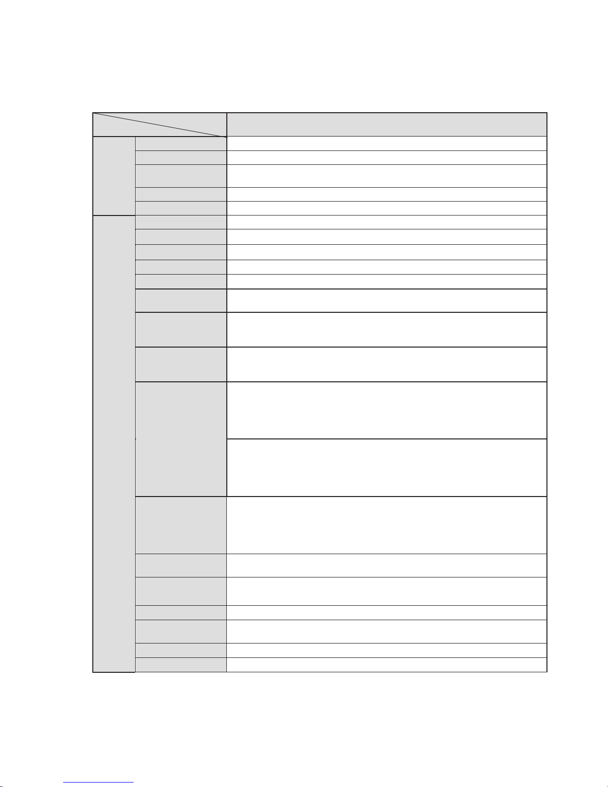
6SHFLILFDWLRQV
Model
Parameter
IP
System
Main Processor
TI Davinci high performance DSP
OS
Embedded LINUX
System
Resources
Support real-time network, local record, and remote operation at the
same time.
User Interface
Remote operation interface such as WEB, DSS, PSS
System Status
Bit stream statistics, log, and software version.
Video Parameter
Image Sensor
1/3-inch CMOS
Pixel
1280(H)*960(V)
Day/night
Support IR-CUT switch
Gain Control
Fixed/Auto
White Balance
Manual/Auto
BLC
Off/BLC/WDR (1-100 adjustable)/HLC(anti-flicker is outdoor and is
valid only when exposure mode is auto with range 1-100)
Exposure Mode
Manual/Auto
PAL: It ranges from 1/
NTSC: It ranges from 1/4 to 1/10000
Video
Compression
Standard
H
Video Frame
Rate
PAL:
Main stream
extra stream
Main stream
extra stream ( 704*576@25fps)
NTSC:
Main stream
extra stream
Main stream
extra stream ( 704*480@30fps)
Video Bit Rate
H.264: 56Kbps-6144Kbps
H.264H
H.264B 56Kbps
MJPEG
Support customized setup.
Video Flip
Support mirror.
Support flip function.
Snapshot
Max 1f/s snapshot. File extension name is JPEG.
Privacy Mask
Supports max 4 privacy mask zones
Video Setup
Support parameter setup such as bright, contrast.
Video
Information
Channel
Lens
2.8mm, 3.6mm, 6mm, 8mm. Fixed focus.
Lens Interface
M12. Lens is the default accessories
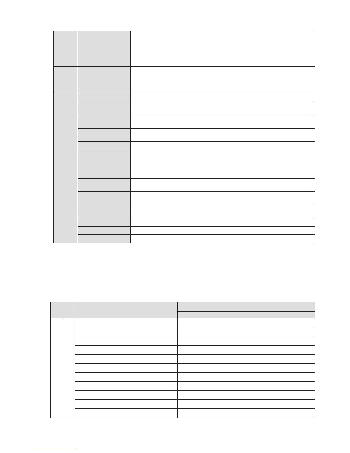
Please refer to the following sheet for network camera performance specification.
-73
3 to 1/10000
.264/H.264H/H.264B/MJPEG
(1280*960@15fps),
( 704*576@15fps)
(1280*720@25fps),
(1280*960@15fps),
( 704*480@15fps)
(1280*720@30fps),
: 16Kbps-6144Kbps
-6144Kbps
: adjustable and bit rate is adjustable.
title, time title, motion detect, camera masking.
Page 23
3
Video
Motion Detect
396 (18*22) detection zones; sensitivity level ranges from 0 to 10 0;
area threshold ranges from 0 to
Activation event: video storage, image snapshot, log, email function
and etc.
Record
Record Priority
Manual>External alarm >Video detect>Schedule
Wire Network
1-ch 10/100 M Ethernet , RJ45 port
Network Protocol
HTTP, TCP/IP, ARP, RTSP, RTP,UDP, RTCP, SMTP, FTP, DHCP,
DNS, DDNS, PPPOE, IPv4/6, SNMP, UPNP, NTP
Remote
Operation
Monitor, system setup, file download, log information, maintenance ,
upgrade and etc
Restore Default
Setup
Built
IR light
IR light 15M.
Power
DC12V power and PoE.
Warning
Do not connect these two power supplying sources to the device
at the same time; it may result in device damage!
Power
Consumption
4.5
Working
Temperature
-10
Working
Humidify
10%~90%
Dimensions(mm)
Φ 113h86
Weight
280g(Excluding box)
Installation
Fixed on the wall, ceiling and etc.
)DFWRU\'HIDXOW6HWXS
Setup
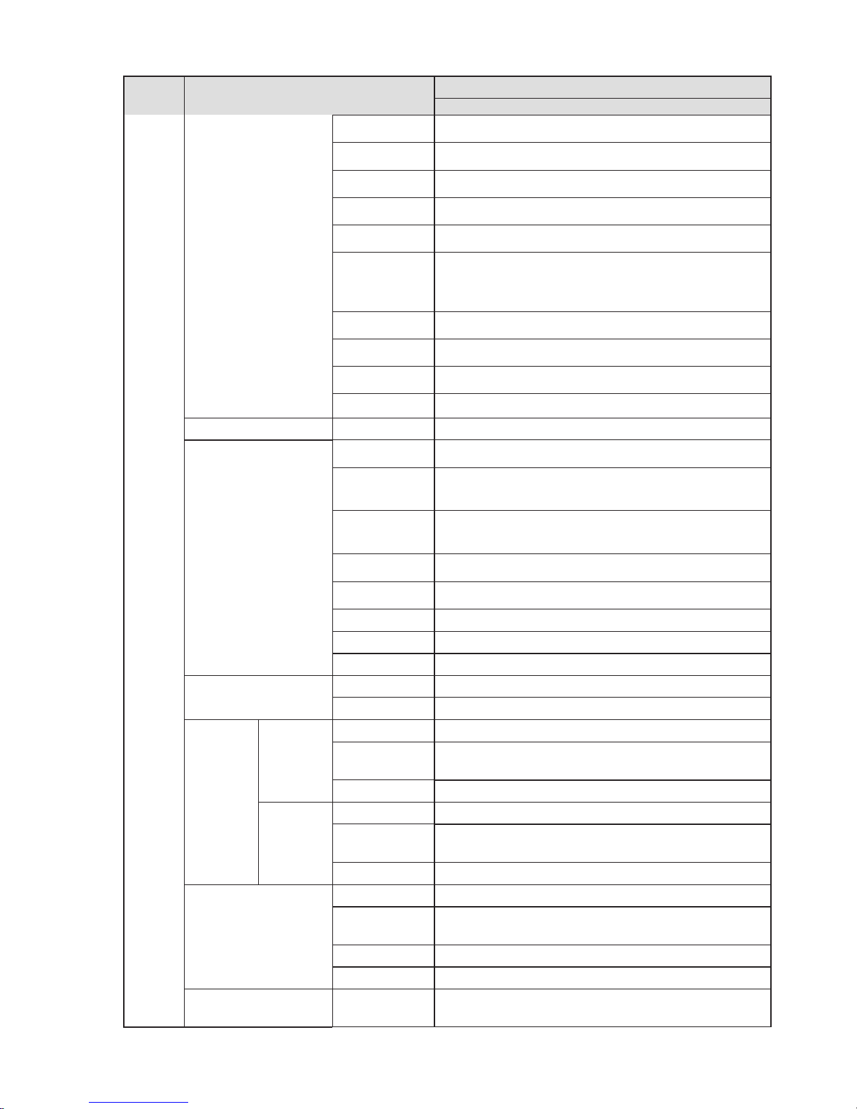
Item
Default Setup
IP-73
Camera Conditions
Config File
Normal
Brightness
50
Contrast
50
Sharpness
50
Saturation
50
Anti-flicker
Outdoor
Exposure Mode
Auto
Scene Mode
Auto
Day/night Mode
Auto
BLC
Off
Mirror
Off
Network
-in Reset button
General Parameter
ʽʽ
W MAX
100.
ć~+60ć
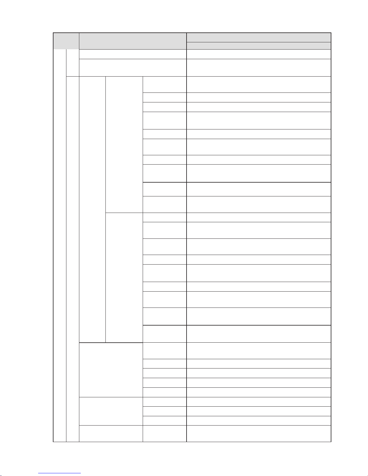
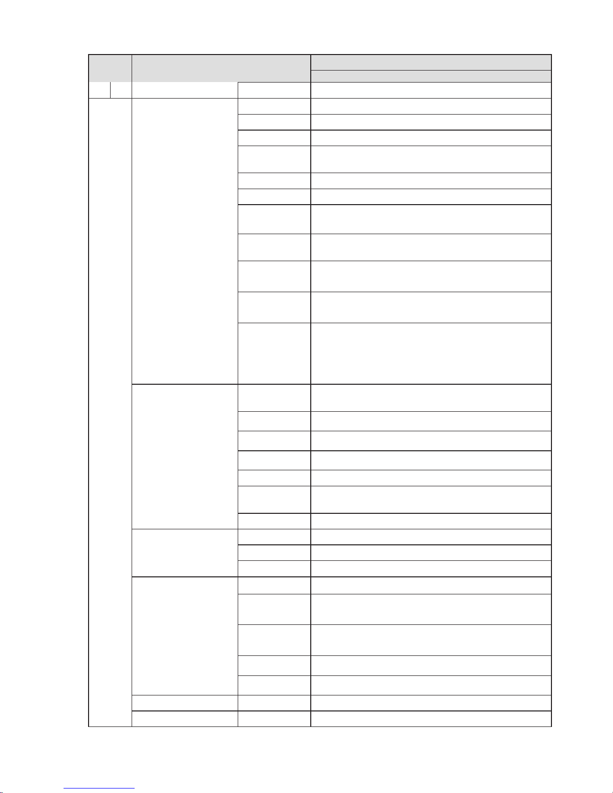
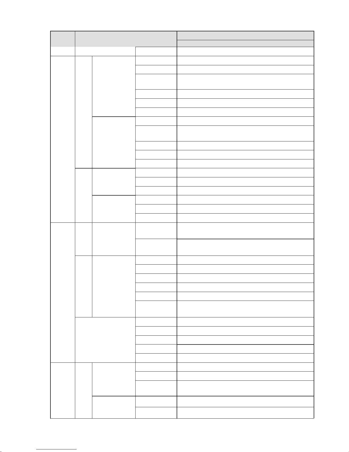
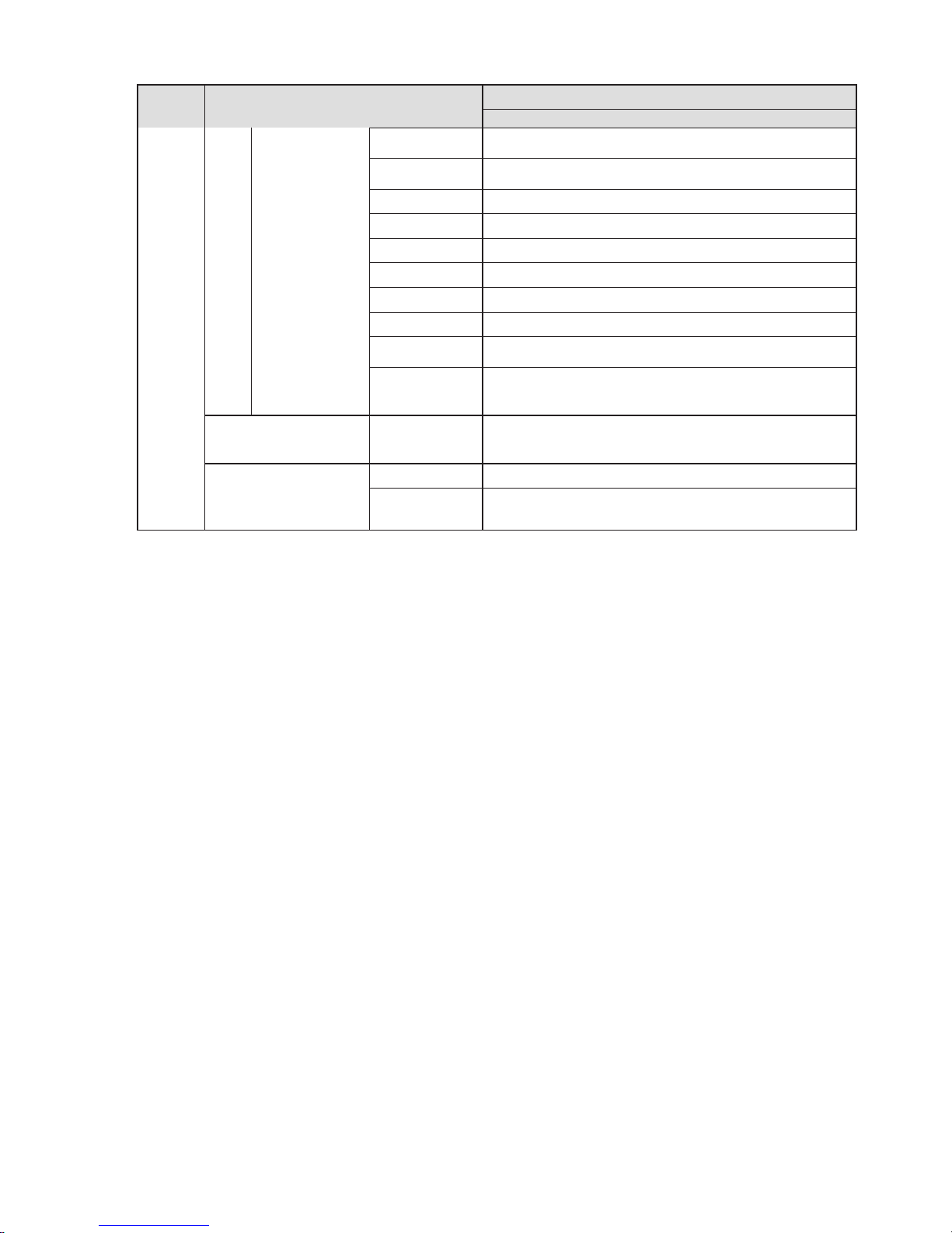
Please refer to the following sheet for factory default setup information.
Page 24
4
Setup
Item
Default Setup
IP-73
Flip
Off
Prof
Normal
Video
Video bit stream
Main
Stream
Bit stream
type
General
Encode mode
H.264
Resolution
720P (1280*720)
Frame
Rate(FPS)
PAL: 25
NTSC:30
Bit Rate Type
CBR
Recommende
d Bit
1536
Bit Rate
4096
I Frame
interval
50
Watermark
Enable
Watermark
character
DigitalCCTV
Sub
Stream
Enable
Enable
Bit stream
type
General
Encode
mode
H.264B
Resolution
CIF(352*288)
Frame
Rate(FPS)
PAL: 25
NTSC:30
Bit Rate Type
CBR
Recommend
ed Bit
192
Bit Rate
512
I Frame
interval
50
Snapshot
Snapshot
Type
General
Image Size
720P (1280*720)
Quality
Better
Bit Rate
Main stream
Interval
1s
Video Overlay
Privacy Mask
Disable
Channel Title
Enable
Time Title
Enable
Path
Snapshot
Path
C:
ile Management
-6124Kb/S
-1024Kb/S
\PictureDownload
Page 25
5
Setup
Item
Default Setup
IP-73
Record Path
C:\RecordDownload
Network
TCP/IP
Host Name
IPC
Ethernet Card
Wire
Mode
Static
Mac Address
Device MAC address when it is shipped out of the
factory
IP Version
IPV4
IP Address
192.168.1.108
Subnet Mask
255.255.255.0
Default
Gateway
192.168.1.1
Preferred
DNS
8.8.8.8
Alternate
DNS
8.8.8.8
Enable
ARP/Ping set
device IP
address
service
Enable
Connection
Max
Connection
10
TCP Port
37777
UDP Port
37778
HTTP Port
80
RTSP Port
554
Enable
HTTPs
Disable
HTTPs Port
443
PPPoE
Enable
Disable
Username
none
Password
N/A
DDNS
Server Type
DisableˈCN99 DDNS
Server
Address
www.3322.org
Domain
Name
none
Username
none
Password
****
IP Filter
Trusted sites
Disable
SMTP(Email)
SMTP Server
none
Page 26
6
Setup
Item
Default Setup
IP-73
Port
25
Anonymity
Disable
User Name
anonymity
Password
****
Sender
none
Authenticatio
n (Encryption
mode)
N/A
Title (Subject)
IPC M
Attachment
Enable
Mail Receiver
0
Email Test
Disableˈinterval=60 seconds
UPnP
Enable UPnP
Disable
SNMP
SNMP Port
161
Read
Community
public
Write
Community
private
Trap Address
N/A
Trap Port
162
SNMP v1
Disable
SNMP v2
Disable
SNMP v3
Disable
Bonjour
Enable
Enable
Server Name
Device factory SN
Multicast
Main
Stream
Enable
Enable
Multicast
Address
239.255.42.42
Port
36666
Extra
Stream
Enable
Disable
Multicast
Address
239.255.42.42
Port
36667
IEEE802
Enable
Disable
Authenticatio
n
PEAP
Username
None
Password
****
QoS
Real-time
Monitor
0
essage
seconds
Page 27
7
Setup
Item
Default Setup
IP-73
Command
0
Event
Video detect
Motion Detect
Enable
Disable
Anti-dither
5 seconds
Record
Channel
Enable
Record Delay
10 seconds
Send Email
Disable
Snapshot
Disable
Video
Ma
Enable
Disable
Record
Channel
Enable
Record Delay
10 seconds
Send Email
Disable
Snapshot
Disable
Abnormity
Disconnection
Enable
Disable
Record
Enable
Record Delay
10 seconds
IP Conflict
Enable
Disable
Record
Enable
Record Delay
10 seconds
Storage
Schedule
H
Schedule
Record
Disable
Snapshot
Disable
Storage
FTP
Enable FTP
Disable
Server IP
N/A
Port
21
Username
anonymity
Password
N/A
Remote path
Share
Record Control
Pack Duration
8 minutes
Pre-record
5 seconds
Disk Full
Overwrite
Record Mode
Auto
Bit Stream
Main Stream
System General
Local Host
Device No
Device factory SN
Language
English
Video
Standard
PAL/NTSC
Date and time
Date Format
Y
Time Format
24H
sking
oliday
-M-D
Page 28
8
Setup
Item
Default Setup
IP-73
Time Zone
GMT+08:00
System Time
Sync
DST
Disable
DST Type
Date
Start Time
00:00:00 of Jan.1st
End Time
00:00:00 of Jan.2nd
NTP
Disable
NTP Server
clock.isc.org
Port
123
Update
Perio
10 minutes
Account
Anonymous
Login
Disable
Auto Maintenance
Auto Reboot
Enable, Tuesday 02:00
Auto Delete
Old Files
Disable
d
Page 29
9
6WUXFWXUH
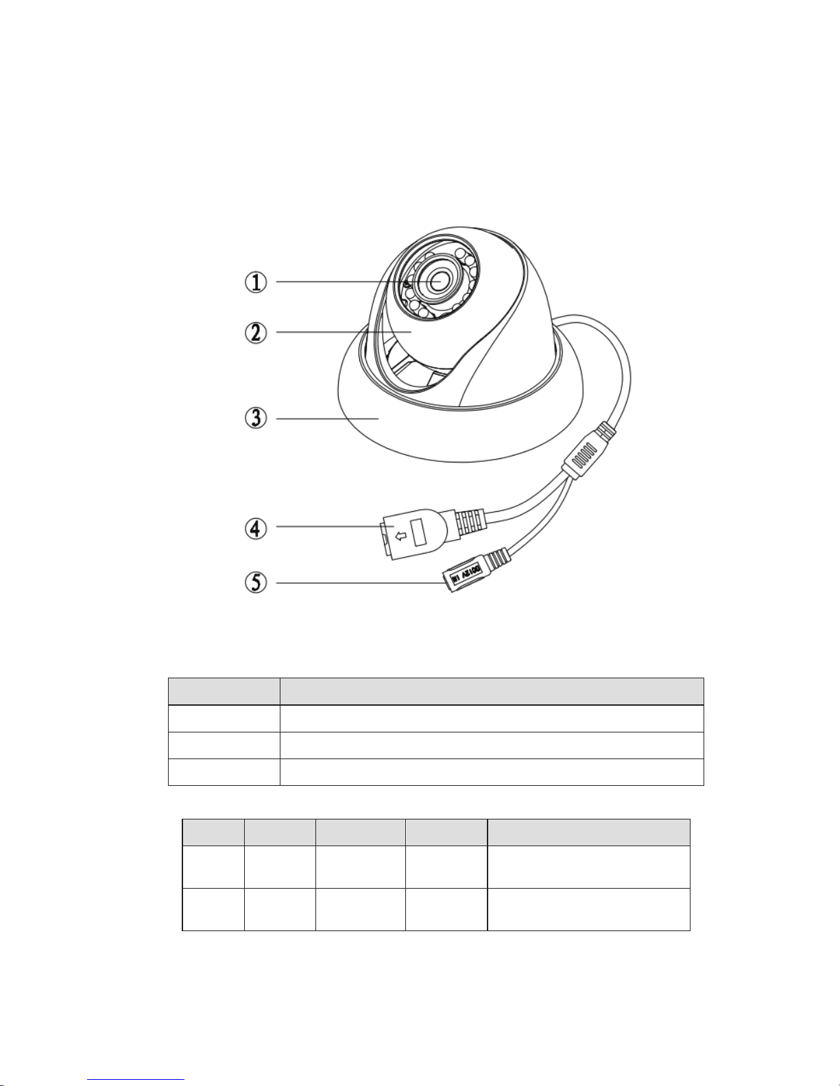
&RPSRQHQWV
No. Port Name
Connector
Note
4
LAN
Network
port
Ethernet
To connect
standard
Ethernet.
5
DC12V
DC 12V
power
To connect to
power
supply.
)UDPHZRUNDQG'LPHQVLRQ
Component
Component Name
Component 1
D
Component 2
Dome body
Component 3
Dome enclosure
You can refer to the following figure for multiple-function combination cable information. See Figure
2-1
.
Figure 2-1 Multiple-function combination cable
Please refer to the following sheet for detailed information.
evice lens
to
DC12V
Page 30
10
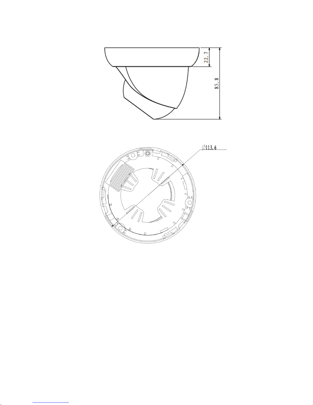
Please refer to the following two figures for dimension information. The unit is mm. See Figure 2-2 and
Figure 2-3.
Figure 2-2 Dimension illustration 1
Figure 2-3 Dimension illustration 2
Page 31
11
'HYLFH,QVWDOODWLRQ
,QVWDOODWLRQ6WHSV
Important
Before the installation, please make sure the installation environments can at least support 3x weight
of the camera.
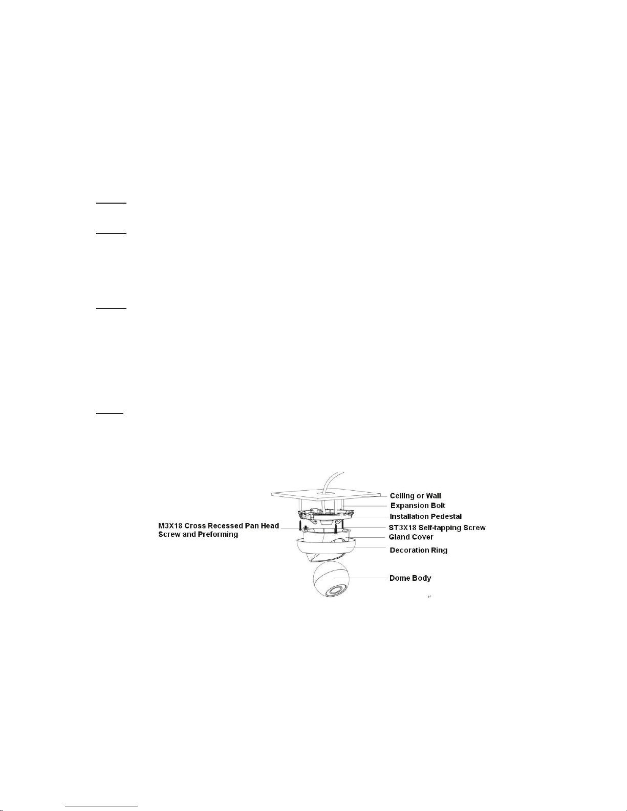
Please follow the steps listed below to install the device. Please refer to Figure 3-1 for reference.
Step 1
Turn clockwise to remove the decoration ring from the snap joints.
Step 2
Please take the installation position map in the accessories bag, and then paste it on the ceiling or the
wall according to your monitor area requirements. Draw and then dig three plastic expansion bolts
holes in the installation surface and then insert three expansion bolts in the holes. Secure these three
bolts firmly. Please draw the cable out from the cable exit when you install the device.
Step 3
Adjust the device installation pedestal to the proper position and then line up the three screw holes in
the device pedestal to the three plastic expansion bolt holes in the installation position. Put the three
self-tapping screws in the three plastic expansion bolts firmly. Loosen the M3X8 cross recessed pan
head slot screw of the pedestal to unfasten the preforming. (Do not remove, loosen a little bit will be
OK.). Adjust the lens to the proper monitor angle and then use the original preforming to turn the M3X8
cross recessed pan head slot screw back.
Step4
Line up the three spigots of the decoration ring to the jags from the bottom to the top and then turn
clockwise until you hear a clear sound ”KA”. Now the installation is complete.
Important
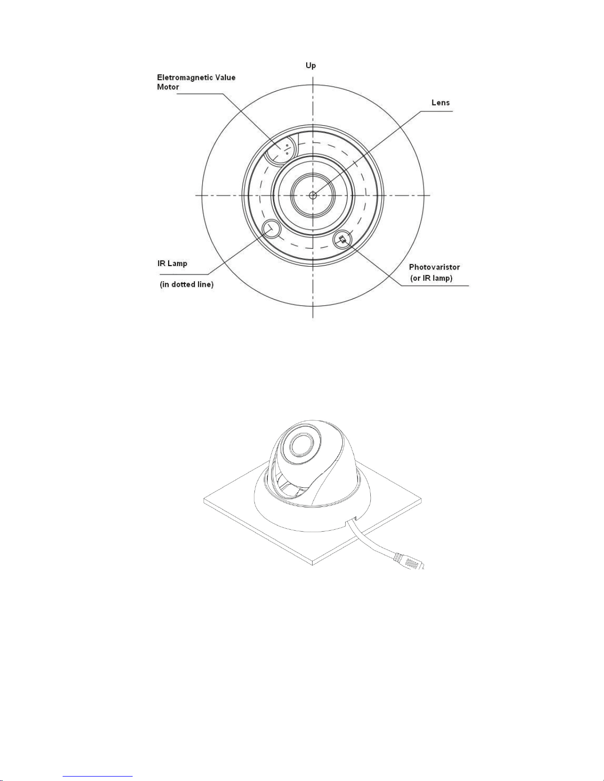
Please pay attention to the dome camera direction when you are installing. Please refer to the
following figure for detailed information. See Figure 3-2.
Figure 3-1 Device installation illustration 1
Page 32
12
Figure 3-2 Device installation illustration 2
Note
This series product supports two cable exits. One is from the bottom and the other is from the side.
Please refer to the following figure for cable exit from the side information.
Figure 3-3 Device installation illustration 3
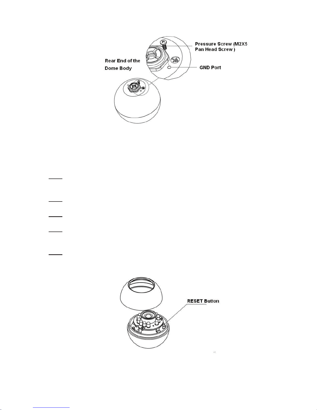
Please earth the GND port of the device to enhance the device reliability. The GND port is near the
cable exit port on the rear of the dome. The GND screw uses the M2X5 pan screw.
Page 33
13
5HVWRUH)DFWRU\'HIDXOW6HWXS,QWURGXFWLRQ
Figure 3-4 Device installation illustration 4
Important
Please use RESET button when device is running.
Step1
Please refer to step1 and step2 in chapter 3.1to loose the dome body. Push a little bit; you can take
the dome body from the gland cover.
Step2
Take the dome body out and then turn the top cover hard to remove.
Step3
Slightly press the RESET button to complete the reset function. See Figure 3-5.
Step4
Turn the top cover back to the original position. Please make sure it reaches the original position,
otherwise it may result in water leakage!
Step5
Put the dome back to the gland cover. Please refer to step4 in chapter 3.1 to install the decoration ring
back.
Figure 3-5 Reset
Page 34
14
4 Quick Configuration Tool
4.1 Overview
Quick configuration tool can search current IP address, modify IP address. At the same time, you can
use it to upgrade the device.
Please note the tool only applies to the IP addresses in the same segment.
4.2 Operation
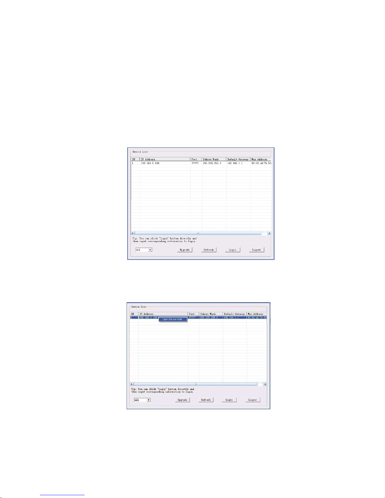
Double click the “ConfigTools.exe” icon, you can see an interface is shown as in Figure 4-1.
In the device list interface, you can view device IP address, port number, subnet mask, default
gateway, MAC address and etc.
Figure 4-1 Search interface
Select one IP address and then right click mouse, you can see an interface is shown as in Figure 4-2.
Select the “Open Device Web” item; you can go to the corresponding web login interface.
Figure 4-2 Search interface 2
If you want to modify the device IP address without logging in the device web interface, you can go to
the configuration tool main interface to set.
Page 35
15
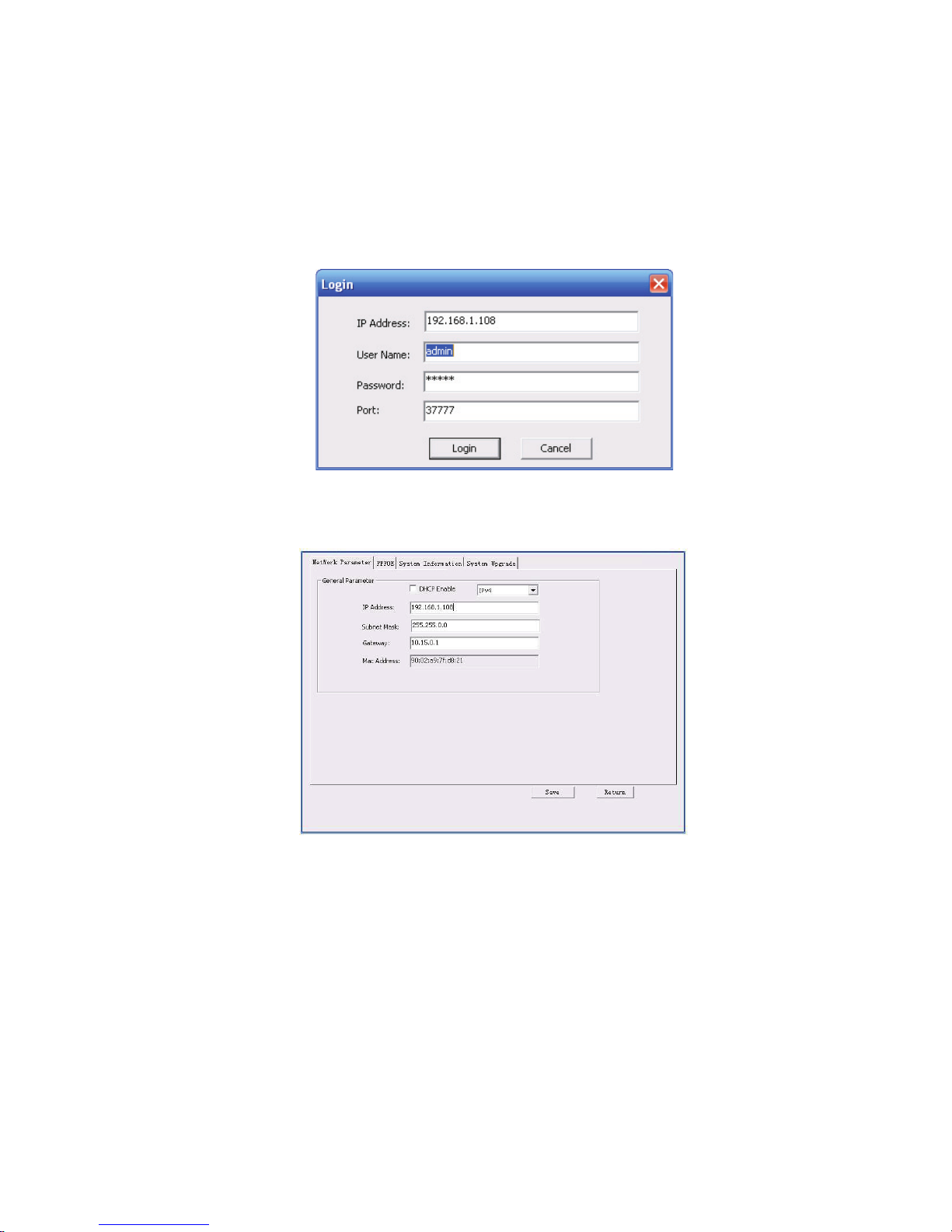
In the configuration tool search interface (Figure 4-1), please select a device IP address and then
double click it to open the login interface. Or you can select an IP address and then click the Login
button to go to the login interface. See Figure 4-3.
In Figure 4-3, you can view device IP address, user name, password and port. Please modify the
corresponding information to login.
Please note the port information here shall be identical with the port value you set in TCP port in Web
Network interface. Otherwise, you cannot login the device.
If you are using device background upgrade port 3800 to login, other setups are all invalid.
Figure 4-3 Login prompt
After you logged in, the configuration tool main interface is shown as below. See Figure 4-4.
Figure 4-4 Main interface
For detailed information and operation instruction of the quick configuration tool, please refer
to the Quick Configuration Tool User’s Manual included in the resources CD.
Page 36
16
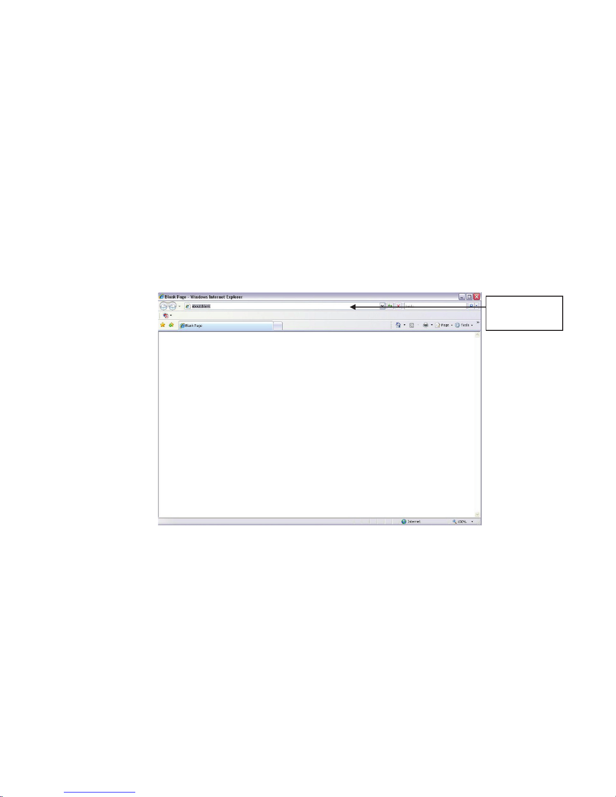
Input your IP
address here
5 Web Operation
This series network camera products support the Web access and management via PC.
Web includes several modules: Monitor channel preview, system configuration, alarm and etc.
5.1 Network Connection
Please follow the steps listed below for network connection.
z Make sure the network camera has connected to the network properly.
z Please set the IP address, subnet mask and gateway of the PC and the network camera
respectively. Network camera default IP address is 192.168.1.108. Subnet mask is 255.255.255.0.
Gateway is 192.168.1.1
z Use order ping ***.***.***.***(* network camera address) to check connection is OK or not.
5.2 Login and Main Interface
Open IE and input network camera address in the address bar. See Figure 5- 1.
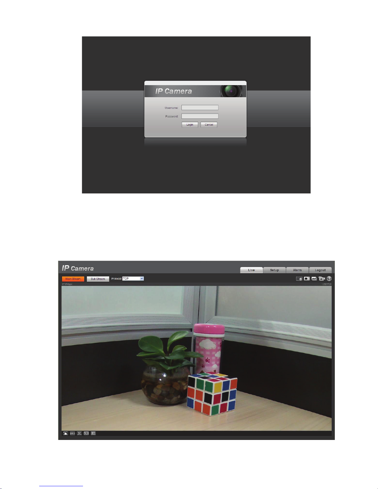
The login interface is shown as below. See Figure 5- 2.
Please input your user name and password.
Default factory name is admin and password is admin.
Note: For security reasons, please modify your password after you first login.
Figure 5- 1 IP address
Page 37
17
Figure 5- 2 Web login
If it is your first time to log in, system pops up warning information to ask you whether install web plug-
in or not after you logged in for one minute. For detailed plug-in installation, please refer to the Web
Operation Manual included in the resource CD.
After you logged in, you can see the main window. See Figure 5- 3.
Figure 5- 3 Web monitoring window
Page 38

18
Please refer to the Web Operation Manual included in the resource CD for detailed operation
instruction.
Page 39

19
)$4
Bug
I can not boot up
the device
operate properly.
Please click RESET button for at least five seconds to restore
factory default setup.
The water leakage
occurred.
The unauthorized front or rear cap remove many result in water
leakage.
The glass front
The
IR video is poor.
Do not use the proper
power. The IR light can not turn on
completely.
The object is out of the IR distance range of current device.
IR
of
the front
I can not upgrade
the device via
network.
W
ou can use port 3800 to
continue upgrade.
I can not login the
client
end or the
WEB.
For Windows OS 98 or Windows ME user, if you can not install the
client
end or can not view after the installation. We recommend the
w
The Active X control is blocked.
The display card version shall
Network connection error
Invalid network setup.
Invalid user name or password.
I can not play the
download file.
There is no player.
There is no DX8.1 or higher.
For the MEDIA PLAYER, there shall be Div X503Bundle.exe plugin
if you play the .AVI file.
For Windows XP user, you need to install the plugin
DivX503Bundle.exe and ffdsho
To guarantee
setup update
After you modified the important setup, please reboot the device via
the software to make sure the setu
storage medium.
Power adapter
The
The
device
when the temperature
exceeds the working temperature
Please replace an industry-level power adapter if you are using in
the harsh environments.
or
in2000sp4 OS or install the client-end of the low version.
waterproof plug of the rear cap becomes loosen.
-CUT does not turn to the night mode. The photosensitive chip
-end can not sense the IR light.
hen network upgrade operation failed, y
-
cap has sustained heavy push or strike.
supplying
be dx8.1 or higher.
occurred.
general power adapter can work ranging from 0ć to 40 ć.
may result in unstable power supply
-2004 1012.exe.
p has been updated to the
.
Page 40
20
$SSHQGL[7R[LFRU+D]DUGRXV0DWHULDOVRU(OHPHQWV
Component
Cr VI
Circuit Board
Component
ase
Wire and Cable
Packing
Components
Accessories
○ ○ ○ ○ ○
○
$
Toxic or Hazardous Materials or Elements
Name
Device C
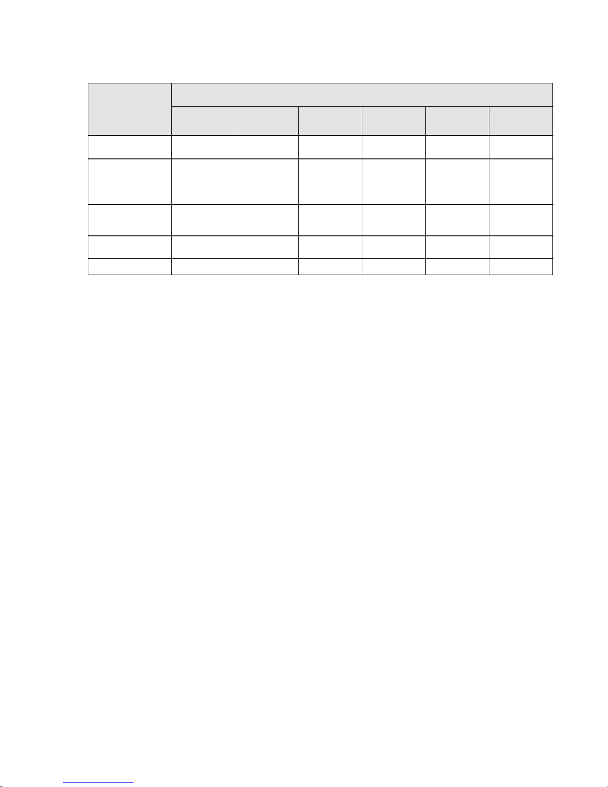
O: Indicates that the concentration of the hazardous substance in all homogeneous materials in the
parts is below the relevant threshold of the SJ/T11363-2006 standard.
X: Indicates that the concentration of the hazardous substance of at least one of all homogeneous
materials in the parts is above the relevant threshold of the SJ/T11363-2006 standard. During the
environmental-friendly use period (EFUP) period, the toxic or hazardous substance or elements
contained in products will not leak or mutate so that the use of these (substances or elements) will not
result in any severe environmental pollution, any bodily injury or damage to any assets. The consumer
is not authorized to process such kind of substances or elements, please return to the corresponding
local authorities to process according to your local government statutes.
Note
Pb Hg Cd
○ ○ ○ ○ ○ ○
○ ○ ○ ○ ○ ○
○ ○ ○ ○ ○ ○
○ ○ ○ ○ ○ ○
PBB
PBDE
z This user’s manual is for reference only. Slight difference may be found in user interface.
z All the designs and software here are subject to change without prior written notice.
z All trademarks and registered trademarks mentioned are the properties of their respective
owners.
z If there is any uncertainty or controversy, please refer to the final explanation of us.
z Please visit our website for more information.
Page 41
software
•
NOT
FOR
SALE
Page 42

POWERED BY
ClearView
A Clear Choice
ClearView CCTV products are professional quality equipment, and we stand behind our products with a 7 Year Warranty.
ClearView CCTV will replace, or at its sole discretion repair without charge, any DVR (Digital Video Recorder),
NVR (Network Video Recorder) Camera or accessory proved defective in material, workmanship or operation for a period of
If during the warranty period, we cannot repair your product, we will replace the product with a working product of the
seven (7) years, subject to warranty conditions and exceptions below.
same model, or if the same model is not available, with a comparable product.
Seven (7) Year Warranty
Conditions & Exceptions:
1. Dated proof of purchase with covered unit serial numbers is required for warranty service.
Please include a copy of your receipt with your return.
2. All goods requiring warranty repair require acquiring an authorized Return Materials Authorization (RMA) number.
RMA numbers can only be issued by ClearView CCTV technical representatives via email ([email protected])
or by calling the support line at (786) 454-9372.
3. Service returns must have the issued RMA number displayed on the return shipment carton or label.
Returns received without an RMA number visible will be refused and returned to the sender unopened.
4. Service returns must be sent prepaid via a package or freight method that provides a tracking number, to:
ClearView CCTV Inc.
RMA# (use your issued RMA number)
3010 N Andrews Ave EXT
Pompano Beach, FL 33064
5. ClearView CCTV Inc assumes no risk and shall be subject to no liability for damages or loss resulting from the specic use or application
made of the Products. ClearView CCTV’s liability for any claim, whether based on breach of contract, negligence, infringement of any
rights of any party or product liability, relating to the Products shall not exceed the price paid to ClearView CCTV Inc for such Products
or the published MSRP, whichever is less.
6. In no event will ClearView CCTV Inc be liable for any special, incidental or consequential damages (including loss of use, loss of prot
and claims of third parties) however caused, whether by the negligence of ClearView CCTV Inc or otherwise.
7. For warranty repaired or replaced products, ClearView CCTV Inc will warrant all replacement parts and repairs for the remainder of the
original warranty, or 90 days from the date of ClearView CCTV repair/replacement return shipment, whichever is longer.
8. Service and warranty repairs are prorated from the end user date of purchase. For Three (3) years (36 months) after purchase ClearView
covers 100% of replacement or repair costs. After 3 years (36 months), replacement or repair value will prorate for normal wear & tear
by 2.04% per month from date of purchase through the end of warranty period. Warranty is non-transferrable.
9. Repairs made necessary by reason of misuse, alteration, or accident, or cosmetic damage such as nish fading or scratches & scus are
not covered under this warranty.
10. This warranty is void if the product defect is caused by:
• Cracks and/or leaks caused as a result of abnormal normal wear and/or accident, vandalism or abuse;
• Use with non-ClearView CCTV Inc hardware products or software not licensed by ClearView CCTV Inc
(including but not limited to adaptors and power supply sources) or which are otherwise not compatible;
• Unauthorized modication or tampering; opening, disassembly, attempted repair, modied,
or alteration by other than ClearView CCTV Inc authorized repair centers.
• Damage by Acts of God, lighting, power surge, misuse, abuse, over exposure to the sun or elements, negligence, accident,
wear and tear, mishandling, misapplication, intrusion of or exposure to liquids, or other causes unrelated to
defective materials or workmanship;
• If serial number is defaced, altered, or removed;
• Malicious software, programs, data, viruses, or les;
• Use not in accordance with the accompanying documentation and use instructions; or
The above warranty provides the Dealer and consumer with specic legal rights. The Dealer or consumer may also have
additional rights, which are subject to variation from state to state.
 Loading...