

Page 1
HD4112 Manual Rev 2
HD4112 Quad HDMI MPEG2
HD DVBT
Encoder Modulator
U S E R M A N U A L
Page 2

HD4112 Manual Rev. 2
Contents
1. GENERAL
1.1 Description
1.2 Specifications
2. INSTALLATION
2.1 What’s in the Box
2.2 Connection
2.2.1 DEVICE Programming and Setup
3.
OPERATING
INSTRUCTIONS
3.1 Description of controls and components
3.2 Starting
3.2.1 Beginning Setup
3.2.2 Step 1: Login and Adjust RF and stream settings
3.2.3 Step 2: Adjust System Settings
4. FLOW CHART
5.
QUICK MENU GUIDE
5.1 Sub Menu
6. OPERATION VIA FRONT BUTTONS
6.1 System and Info
6.2 Modulation Setting
6.3 Streaming Settings
7. SYSTEM SETTINGS
Page 3

HD4112 Manual Rev. 2
DIGITAL MODULATOR
1. GENERAL
1.1 Description
The HD4112 modulator is able to generate 4 x RF signals in DVB-T format
(Digital Terrestrial Television) from 4 x HDMI inputs.
HD4112 is MPEG-2 encoding, 1080p, DVB-T modulation integrated into one
device to convert 4 x HDMI signals to 4 DVB-T RF out.
The HD4112 is HDCP Compliant and works up to 1080p resolution.
Page 4
HD4112 Manual Rev. 2
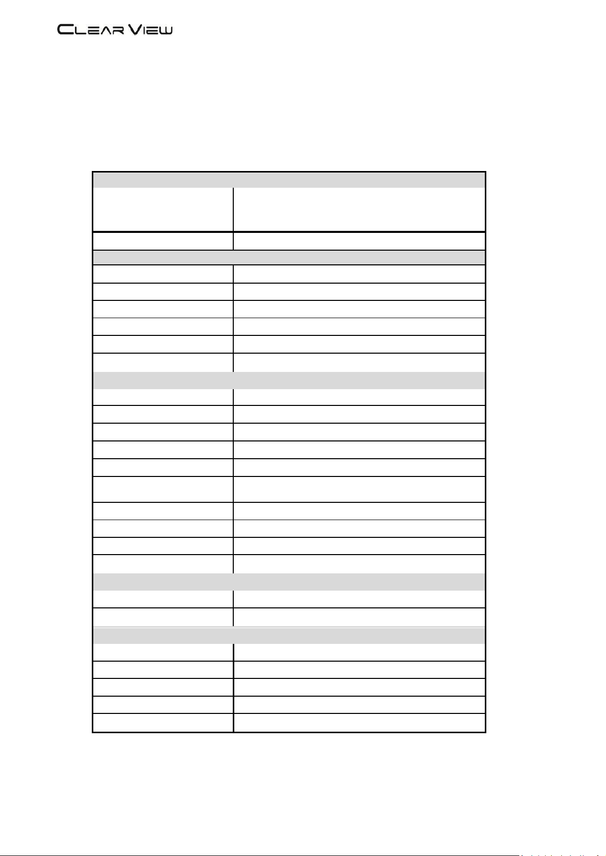
1.2 Specifications
INPUT
Video Input
1080P25, 1080P30,1080i,576i,480i
Input Connectors
4 x HDMI
OUT PUT
Frequency Range
177 -226.5 MHz, 522.5 -816.5 MHz, 4 Carriers Out
Output Level
102 dBuV Max
Channel Bandwidth
7-8 MHz
RF Level Adjustment
70 to 102 dBuV
Attenuation step
1dB per step
MER
36 dB typically
MODULATION
Video Resolution
1920 x 1080, 30p
Video Compression
MPEG2
Audio Compression
MPEG2, AAC
Video Bit Rate
Adjustable 1 to 22Mb/sec
Audio Bit Rate
384Kbits
Editable Field
Service Name, Network ID, Original NET ID,
LCN, Network Name, Bitrate, Modulation Parameters.
Carrier (OFDM Mode)
2K/8K
Guard Intervals
¼, 1/8, 1/16, 1/32
Code Rate (FEC)
½, 2/3, ¾, 5/6, 7/8
Constellation
QPSK/16QAM/64 QAM
MANAGEMENT / CONTROL
Front panel LCD control
6 Local keys on front panel
Web Management
RJ-45 Ethernet port
GENERAL
Power Supply
AC 100~240V 50/60Hz
Consumption
20 W
Languages
English
Dimensions
19” x 12.5” x 1.75”
Weight
1.8Kg
*Specifications subject to change without prior notice.
Page 5

HD4112 Manual Rev. 2
CLEARVIEW
A06, (177.5MHz)
2. INSTALLATION
2.1 What’s in the Box
One HD4112 Encoder / Modulator
One power cable
2.2 Connection
The HD4112 unit comes standard with 4 x HDMI inputs.
Use a quality 75Ω coaxial cable with “F” connectors from the unit’s RF OUT jack to the
distribution system or directly to a television.
Connect the power cord to an appropriately rated AC power outlet.
Once connected to power, the device turns on and it takes about 80 seconds to be
operational. Then the message “Initial Please wait” appears on the display. After 80
seconds the message “CLEARVIEW and the Frequency Out” will be displayed
from RF output 1. Other output channels can be displayed by pressing right or left arrow
buttons.
2.2.1 DEVICE Programming and Setup
Connect an Ethernet cable directly (no Cross Over cable required) to the Ethernet Port
on the rear panel of the encoder and then connect the Ethernet cable to an Ethernet switch
or connect an Ethernet Cable to your PC. The default IP address is 192.168.1.138
Make sure your PC has the same first 3 IP sections, eg. 192.168.1.xx and the 4th is different
from 138.
Page 6

HD4112 Manual Rev. 2
2 3 7
1 4 5
9 10 8 11
3. OPERATING INSTRUCTIONS
3.1 Description of controls and components
HD168A
Description
1 LCD Display
Configuration and system status
2 Key PAD / Left
Exit from previous menu.
3
Key PAD / Up
Move between menu selections.
4 Key Centre
OK Button to select item
5 Key PAD / Down
Move between menu selections.
7 Key PAD / Right
Move between menu selections.
8 Ethernet Port
RJ-45 Chrome
9
AC input
AC 100 to 240V / 50~60Hz
10
HDMI Inputs
Up to 1080p resolution
11
RF output
“F”-Female 75Ω
ATTENTION!
FOR THIS CONFIGURATION YOU SHOULD USE OUTPUT FREQUENCIES DIFFERENT FROM THE ONES THAT YOUR TV IS CURRENTLY USING
Page 7

3.2 Starting
3.2.1 Beginning Setup
DEVICE Programming and Setup
1. Apply power.
2. Connect Audio / Video source
Connecting to the GUI Interface:
1. Connect an Ethernet cable directly to the Ethernet port on the rear panel of the encoder
and then connect the Ethernet cable to an Ethernet switch /router or connect an
Ethernet Cable to your PC.
2. Using a Windows-based PC Select Windows Icon
3. The default IP address is 192.168.1.138 Make sure your PC has the same 3 first section IP
range.
4. Key in the IP address in web browser 1 9 2 . 1 6 8 . 1 . 1 3 8
3.2.2 Step 1: Login and Adjust RF and Stream Settings
Login Password:
Default Password: 1 2 3 4
Encoder Programming and Setup via GUI Interface and click on SETUP then on
SETUP/RF Out:
Set your channel here for each channel. Once set press the Save Settings button to the left.
It is the same with Output Level, QAM, LCNs, CN, FFT and GI. After setting parameters and
Saving, make sure you press ‘Save Setting & Reboot System’ so settings are permanently
stored.
Page 8

3.2.3 Step 2: Adjust Transport Stream Settings
Click on SETUP then on SETUP/TS:
Set your TS settings for each channel then press Save Settings at the left-hand side.
Once you have set all parameters and pressed Save Settings, finally press
Save Setting and Reboot System to store permanently. The Bitrate setting must not exceed
The allowable amount according to your modulator parameter settings. Please use the
Chart below to determine the maximum bitrate value.
CR GI QPSK 16QAM 64QAM
1/2 1/32 4.486 8.972 13.458
1/16 4.354 8.708 13.062
1/8 4.112 8.224 12.336
1/4 3.701 7.401 11.103
2/3 1/32 5.981 11.962 17.945
1/16 5.805 11.611 17.414
1/8 5.483 10.965 16.449
1/4 4.934 9.869 14.804
3/4 1/32 6.729 13.458 20.188
1/16 6.531 13.062 19.594
1/8 6.168 12.336 18.506
1/4 5.551 11.103 16.654
5/6 1/32 7.477 14.954 22.431
1/16 7.257 14.514 21.771
1/8 6.854 13.707 20.562
1/4 6.168 12.336 18.506
7/8 1/32 7.851 15.702 23.552
1/16 7.620 15.239 22.859
1/8 7.196 14.393 21.590
1/4 6.477 12.954 19.431
Page 9

4. Flow Chart
Page 10

5. Quick Menu Guide
Page 11

5.1 Sub Menu
Page 12

6. Operation Via Front Buttons
6.1 System & Info
6.2 Modulation Setting
Page 13

6.3 Stream Setting
USB Upgrade
1) Download software to USB disk. Unzip. Only 'image.hex' from the HD4112 folder should
be on the USB stick.
2) Insert the USB stick to the slot of USB Upgrade while HD4112 is powered off.
3) Keep pressing the OK button and power on HD4112. One LED illuminates and flickers.
4) Release the OK button. LED continues to flicker. Software upgrade is finished when LED
stops flickering, and the unit says upgrade complete on the LCD panel.
5) Power off HD4112 and then power on again.
Page 14

7. System Setting
Press Setup then Setup System
You can reset the unit to Factory Default or just Hardware Reset by clicking on this
dropdown here. Be sure to always press the Save Settings to the left after selecting your
option. The IP Address of the unit can be adjusted in the 192.168 range. The last 2 sections
are adjustable here.
You can save the Modulator Config by pressing This Button.
It can be re-loaded by Choosing the File then uploading it into the Modulator.
After all settings have been adjusted always press theStore Settings and Reboot System for them to be saved completely.
When using more than one unit in an installation, use the RACK POSITION feature
To set parameters differently in each modulator in the rack so they do not interfere with
each other. The values can be overridden and saves in the SETUO RF and TS menus if you
have other units in the system with same parameters. Press Rack Position SAVE SETTINGS
to save rack position. It will take a little time to re-boot and save.
If the buttons turn grey while you are adjusting settings, Log out then back in again
To activate them.
The STATUS but only shows you status of the device and changes cannot be made in this
menu.
 Loading...