

Page 1
- --
·-
-.-·--··
Analog Camera
·-~--
..
·---·
··
·····-
··
····-·-
·
----
·
z··-
\
K)
·-
···
·
···
-··
·
·--
·-·
··-·
·-········-···-
-
··
/ User's Manual
...
·--·-
·
-',.,;"
" '>;'
-":-c""'-'""
·
?'·
'':'
.
-.-
,.,.-
_
,-,_.
,
,
,
--~~--,..,·_,,.,
.... .
(
,"
c
-
,
,.
1""
"'.-,.,-
,
.""".
.,.
.
..,
.
~
...
~
,..,
{l!.~
.:f
'
'"
··-···--·-·-····
..
··
·
·
..
Version 1.0.0
Page 2
Welcome
!I
, I
i l
i i
Thank you for purchasing our analog camera!
::
::
This
~ ~
; I
~
:
I
~
i
i l
i!
H
I'
I'
!l
I I,
...,<·
-~-~ ~-~
-
..
- .
.................
user's
Please read the following safeguard and warnings carefully before you
use this series product!
Please keep this
-
'·
-~··---
~
----~-
.
........
.
~----·
.....
~
--
........
. . . - .... ..............
manual
.........
.. -........ ···
...
.. • • • •• .......... .....
user's
··
--..
...
....... ... .....
. .. ................ ..
is
designed to be a reference tool for your system.
manual well for future reference!
. ..
......
._
... " ...
...
.. "'
......
'• " -.
........
....
..
"..
. . --------...
................
'"
...................
·--------
···
·--
·-
·
-·--
·-..
............
·-··--
--
...............
..
"· "
. .. . ....
...................
• . .
................
......
. . .
...
. .. -.......
.. .... ......
. .
....
_ . ............. , ......
.................
. . ................. - - -- -·- ·· -
..............
······
·· ·· ··
·····""
.....
......
"· ·· ·--, .
I'
•'
I '
, .
• '
;I
,.
;;
,,
·
,r
; I
i (
/!
·---~···-
. h . . . ..... . . .
'./
.....
.. .
... .
........
Important
•'
• I
1.
Electrical safety
All installation and operation here should conform
Saf.eguards
and
Warnings
to
your local electrical
!!
safety codes.
1[
, i ll
::
The power shall conform to the requirement
;;
::
Low Voltage) and the Limited power source
:
~
ii
in
; :
i l
!i
::
ii
II
i;
ii
H
i!
li
li
n
ii
rt
!I
n Do not apply power to the camera before completing installation.
the IEC60950-1. ;;
We
assume no liability or responsibility for all the fires or electrical shock !i
caused by improper handling or installation. i!
2.
Transportation security
Heavy stress, violent vibration or water splash are not allowed during
transportation, storage and installation.
3.
Installation
in
the
SELV
is
rated 12V DC or 24V AC
(Safety Extra
::
H
i!
H
~
;i
; I
;l
j l
!!
!!
!!
q
li
l!
!i
!
ll
!i
H :;
ii
Please install the proper power
n
ii
connection.
.,
!i
Always follow the instruction guide the manufacturer recommended. ii
ll
ii
If this product
is
installed
in
cut-off
device during the installation
ii
~ ~
!!
H
I'
the ceiling, please make sure the installation il
i
~
li
position can sustain the min
i
~
n n
'<"
': ....
~::~~::;:
:
::::
:::::~~:::::::::::~~:::-::::::::
::
:::-
.~
:::::::::
~~.-
:.~::::::::::·"
_::~
.~::~.::
:::
::~:::~~-~::.
~:~.:.:::
:
~ . .-:::;::
::::
:::~;:::::-
.::::
SON.
:::~~
-:·
..
: ..
::-.:.
::.
:::::
~h::::-.
:::
:
::::
::
.:~~.-:::
::::::::~:~-:::::::::::
:
~-:::
:
: . ..:::::.:::
:
:::
·.::.:.::::~
::.
:
::.
::::
:~~:
.
:::
::::~:
::.:::
:::·:
·.:
::::.:::
:
::::-~~~~:
~::::·
:.::: :::
:::::
:::::
:
::::-
.:::~"-
User's Manual ( K )
!!
p
::.
::~::
:::::::::::~-:
::::::~:
:.·:~/
01
Page 3

...
·-·
~
·•·
..
Anal9g
9a~~r?
.
....
·
1'
,.
lmporta·nt
J•l
I 1 / I 1 I I
4.
Qualified engineers needed
Safeguards
' '
, I I
1
and
Warnings
All the examination and repair work should be done by the qualified
service engineers.
We
are not liable for any problems caused by unauthorized modifications
i ;
or attempted repair.
..
5.
'
Environment
This series analog camera should
away from direct sunlight or
strong
be
installed in a cool,
light,
inflammable,
dry
explosive
substances and etc.
The working temperature ranges from -300C to
+600C.
Please keep
it away from the electromagnetic radiation object and environment.
is
Please make sure the CCD component
, :
beam device. Otherwise
,.
,,
,,
it
may result
out of the radiation of the laser
in
CCD optical component damage. ;;
Please keep the sound ventilation.
Do not allow the water and other liquid falling into the camera .
·,
;
·,
, ,
6. Accessories
Be sure to use all the accessories recommended by manufacturer.
; :
"
,.
Before installation, please
open
the
package
and
check
components are included.
Contact your local retailer
7.
Daily Maintenance
ASAP
if something
is
broken
in
your package.
Please shut down the device and then unplug the power cable before
you begin daily maintenance work.
Do not touch the CCD optic component.
i i
,,
:;
the dust
on
the lens surface.
Always use the dry soft cloth to clean the device. If there
You
can use the blower to clean !!
is
place
all the
too much
; ,
•
,:
,.
"
"
"
, .,
;,
,,
! '
~
;
,.
;;
,,
"
il
"
,,
"
! I
;;
. ;
, ;
"
;;
il
"
H
:;
II
~
:
.,
"
"
q
i l
:
~
!'
{I
i
~
; I
,.
) !
"
/I
q
d
i !
" ! j
;:
; I
I I
,,
;
~
/ i
I !
:
~
~
~
~
i
dust, please use the water to dilute the mild detergent first and then
~
j
;;
use it to clean the device. Finally use the dry cloth to clean the device.
H
1:
H
Please put the dustproof cap to protect the CCD component when you
!!
i !
:i
do
not use the camera.
n
··
,_
---
-·····--·---------
·-•
""""'"""'
"•"'"'
""
Analog
--
Camera
--------
-------
......... , ............. --...... -.........
--------
. --
...
....... . ...
......
02
-
......
--
.........
...............
...
.......
....
.
..
,..
....................
. ..,
..
. -
......
-,.
.-
..
,.
......
-.. -.
..................
...............
.........................
----
-----
--
---
..
.....
.......
...
---
----------
.........
..........
__
..
___
---------
·-.
......
..........
..
-.------~----·-.·------
..
,._/
Page 4
.,.
,.
__
__
_
__
___ ;___
___
___
__
__
___________ _
'''
,,/,
''
I '
,
r'
I
''
I
1
' '
---
User's Manuai(K)
- -
--
--
..
- - ·-
---
---
--
- ---
-·-··
---- ----
....
-------
--·
-··-
I '
, I
:
--
---
J
f
Table
1
Generallntroduction
' I
1.1 Overview .................
1.2 Features ...
1.3 Functions
1.4 Specifications
1.4.1 700
1.4.2 700
2
Framework
2.1
Dimensions .
2.1.1
2.1
.2
2.2 Structure
..
..
..
............
..
..
.........
....
TVL
ICR Day/Night WDR Dome Camera
TVL ICR Day/Night
................................................................................... 1 0
...
..
...........
700
TVL
ICR
700
TVL
ICR Day/Night
..
.
..
.
...
........
,
...................................................................
..
...
..
....
.. ..
.........
.........
...
..
................
Day/Night
..
....
..
ot
/f
,
................
..
..
..
...
.
...
..
.
..
.
...
....
..
......
............
WDR
WDR
WDR
.
..
.
..
..............
Contents· · ·
..
...........................................
..
.. ..
..
.....................
..
..
...
...
........
..
...
.. ..
.......
.. ....
...
...
...
...
.
.............
..
....
..................
..
...
....
..
.
..
...
..
Vandal Proof Dome Camera
...
.
..
.
....
.
..
.
..
..
..
.......
...
.
...
.........
Dome Camera ......
..
..
........
Vandal Proof Dome Camera
...
..
........
..
.....
..
.
..
.....
..
.
..
..
..
...
.
..
......
.....
..
...
.
.
..
..........
..
..
..
...
...
..
..
..
.
..
..
..
......
....
...
....
.....
.......
.
..
..
....
.......
..
...
...
..
.. ..
..
..
..
...
...
...
...
..
.
..
..
..
05
05
..
05
05
07
.
07
.
08
10
1
1
.
11
0
0
3
lnstallation ................................................................................... 12
3.1
3.2
700 TVL
700
ICR Day/Night WDR Dome Camera Installation
TVL
ICR Day/Night WDR
4 Menu .............................................................................................
4.1
Main Menu
4.2 Main Interface
4.3
Detailed
4.3.1
4.3.2
4.3.3
LE
SHUTIER GAIN .
PICTURE
...
.........................
..........
Operation ...............................................
NS
......
...
ADJUST
........
..
...
.
...
..
...
..
.....
..
.
...
..
..........
..........
...
..
..
Vandal
..
...
Proof Dome Camera
..
...
..
...
.................
...
.......
...
..
..............
...
...
.
..
......
...
..
.......
...
..
..
..
...
..
...
...............
..
..
....................
..
...........
..
.......
..
.......
.
..
.
...
.............
.......
..
..
.
.....
..
Installation
...
..............
..
..
..
..
......................
..
...
................... 24
..
...........
..
......
..
.....
..
..
12
..
16
20
..
.
...
.
20
.................. 23
.
..
...
....
.. ..
..
.. 23
...
24
.....
..
..
.
..
..
...
25
User's
Manual
(
K)
03
Page 5
4.3.4
4.3 .5 WDR .
4.3.6 NR
4.3 . 7
4.3.8 DAY/NIGHT
4.3.9
WHITE BALANCE (WB) ..............................................
...............
..
...
...
(NOISE REDUCE/DE-NOISE)
HLC/BLC ............................
...............................
DIGITAL ZOOM ..........
0 PRIVACY MASK
4.3.1
MOTION DETECT
11
4.3.
4.3.12
4.3.13
SYNC MODE ...........................
CAMERA ID
........................................
............................................. ....................................
4.3.14 LANGUAGE ............
4.3 .15
CAMERA RESET
4.3.16 OTHERS
......
.....................
............
..
.
...
..
..
.
..
.... ....
...
.............
............
...
.............
...
..
......................
..
..
..............
...
...
..
...
.. ..
...
.
..
...
..
...
..
.
..
............
...
.................................... .
..
......
...
..
.......
...........
..
...
..............
....
.................... ...........................
..
....
....
.
..
.........................................
..
.
..
...
......
........................... 26
..
..
.......... ........ 27
...........
..
......................................... 27
...
..
........
..
...
.
.................
.........................................
..
..
...............................
..
.....................
...
..
......
..
...
.
...
............
..
.
..
...
..
..
.............
..................
..
..
..
..
.......
...
...
.......
...
.
..
..
..
....
.
..
..
..
......
.......
..
....
..........
...
................
.... 27
28
..
29
...
.
29
30
30
....
31
..
31
31
..
...
31
Appendix Toxic or Hazardous
Materials or
Elements
.................
32
-
~~
~
-
1'!1
-
~~
.
0.9
-
~~~'
04
Page 6
Overview
1.1
---
---
-
··
···
Manuai(K)
··-.
--
·-
··---
---
-
·-
···--
-·
--
-
--
User's
~-
·
~
General Introduction
·
---
--'
l
This series analog camera adopts the high sensitivity
featuring the high quality video, the lowest distortion, low
is
design.
etc. This series product
It
suitable to be used
is
surveillance
in
process system.
1.2 Features
Support
•
75d8
WDR
range suitable for the
environments.
TVL resolution.
• Clear
Support
•
(BLC)
Support
•
video, over
WDR,
and etc.
and
20
700
high
30
compensation (HLC),
light
de-noise.
High signal to noise ratio (SNR),
impressive video.
Support advanced applications such as digital zoom,
•
stabilization, privacy mask, and motion detect.
surveillance
backlight compensation
CCD and advanced circuit
noise and
system and video
the backlight
in
and
digital
clear
image
Support
•
Support auto white balance function. Restore high definition and more vivid
•
OSD
(on-screen
video.
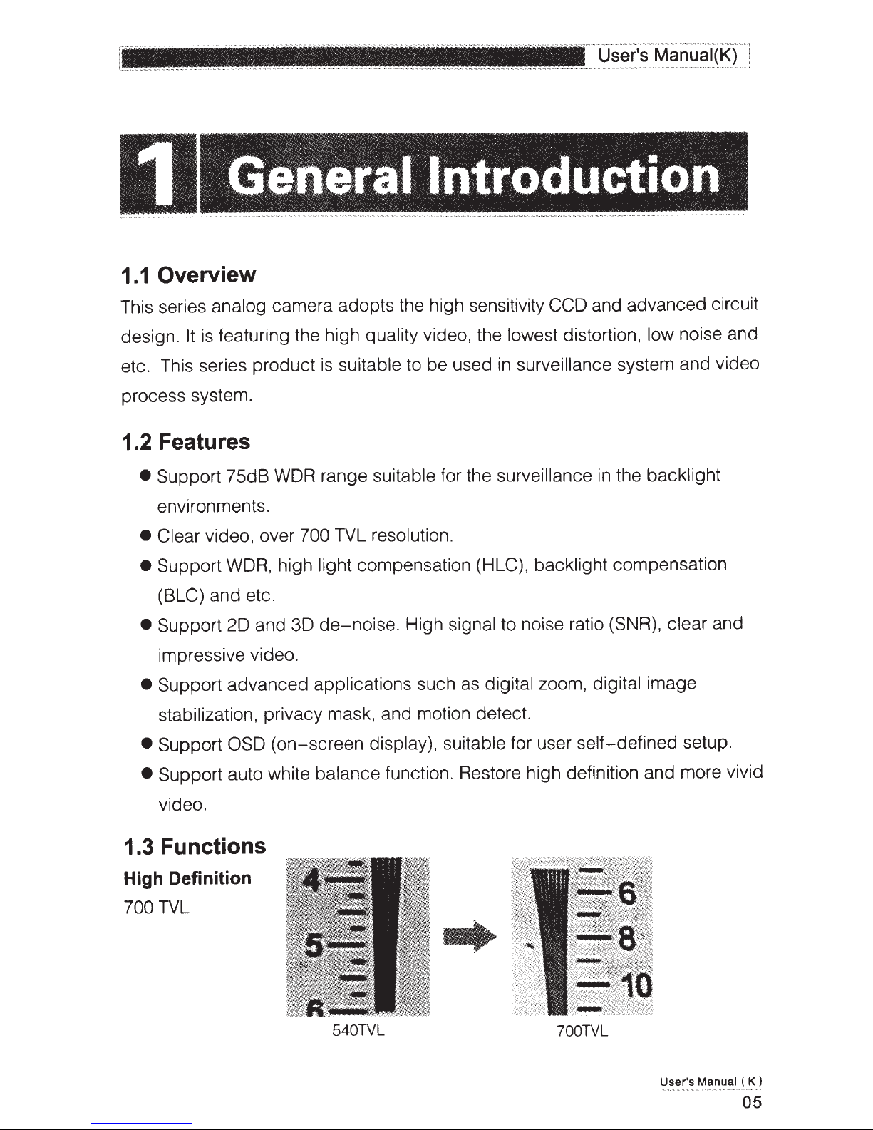
1.3 Functions
High Definition
TVL
700
display), suitable for user self-defined setup.
540TVL
700TVL
User's
Manua
( K )
l
05
Page 7
_
Analog
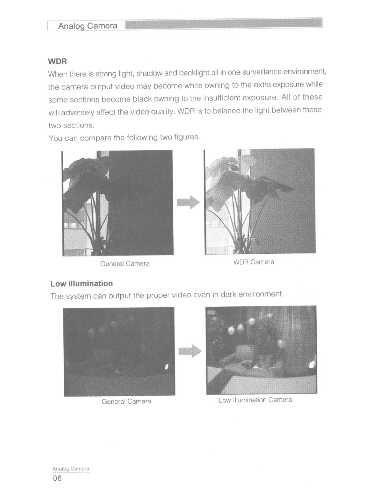
WDR
When there is strong light, shadow and backlight
the camera output video may become white owning to the extra exposure while
some sections become black owning to the insufficient exposure.
Camera
__
all
in
surveillance
one
environment,
these
of
All
adversely affect the video quality.
will
two sections.
following two figures .
You can
illumination
Low
compare
the
General
Camera WDR Camera
WDR
is to balance the light between these
..
The system can output the proper video even in dark environment.
General
Camera
Ana'og
06
Camera Low
Illumination
Camera
Page 8
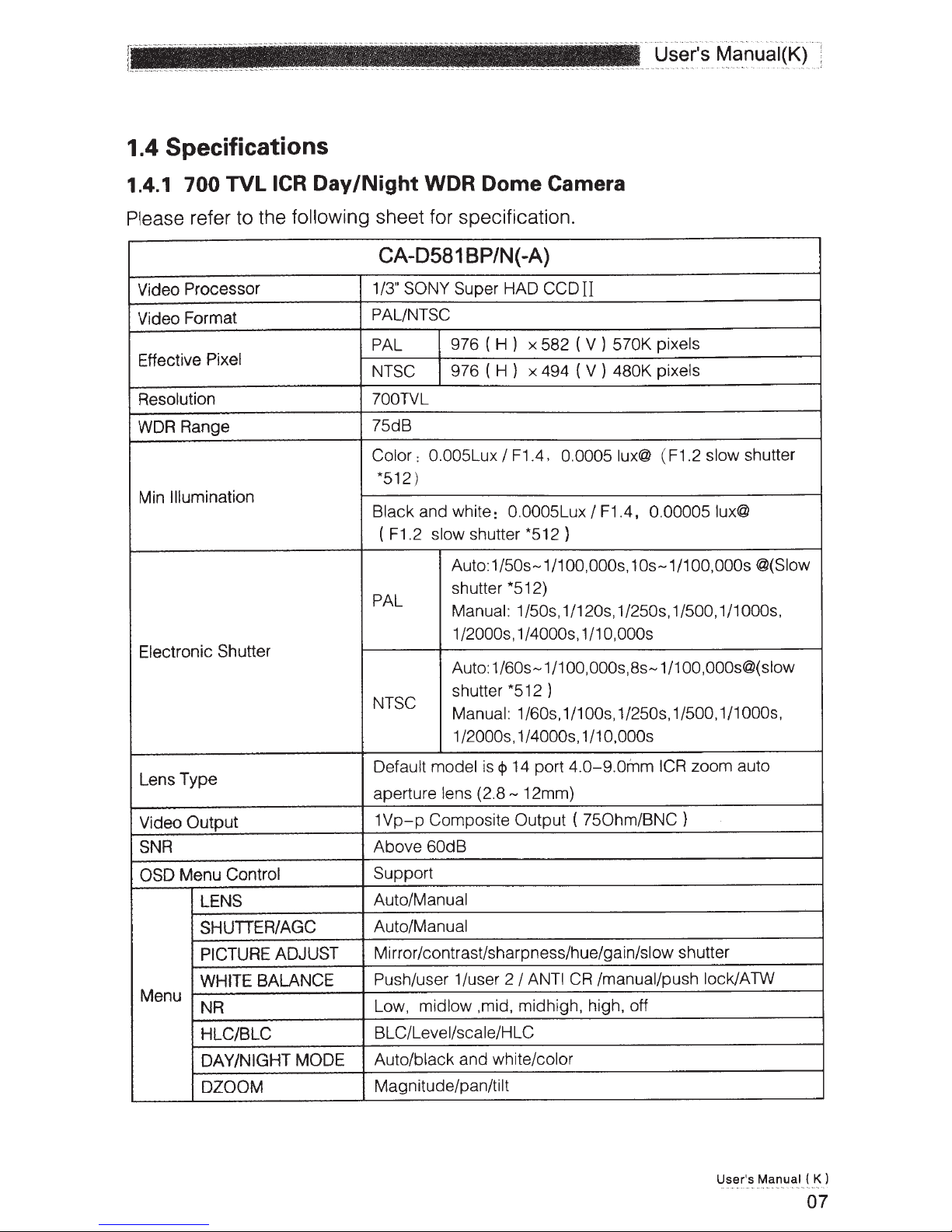
1.4 Specifications
1.4.1 700
Please
Video
Video Format
Effective
Resolution
WDR Range
Min Illumination
Electronic Shutter
TVL
refer to the
Processor 1/3" SONY Super
Pixel
ICR Day
following
/Night
WDR Dome
sheet for specification.
CA-0581 BP/N(-A)
HAD
PALINTSC
(H)
PAL
NTSC
?OOTVL
75dB
Color
*512)
Black and white: 0.0005Lux
F1.2
(
PAL
NTSC
976
976
0.005Lux
:
shutter
slow
Auto:1/50s-1/1
shutter
Manual:
1/2000s, 1/4000s, 1/10,000s
Auto:
shutter *512 )
Manual:
1/2000s, 1/4000s, 1/10,000s
x 582 ( V )
(H)
x 494 ( V )
F1.4,
I
*512)
*512)
1/50s, 1/120s, 1/250s, 1/500, 1/1000s,
1/60s-1/1 00,000s,
1/60s, 1/100s, 1/250s, 1/500, 1/1000s,
Camera
II
CCD
0.0005
F1.4, 0.000051ux@
I
OO,OOOs
pixels
570K
480K pixels
( F1.2 slow shutter
lux@
, 10s-1/100,000s @(Slow
8s-1/100
,000s@(slow
Lens Type
Video
SNR
OSD
Menu
Output
Menu Control
LENS
SHUTIER/AGC
PICTURE ADJUST
WHITE BALANCE
NR
HLC/BLC
DAY/NIGHT MODE
DZOOM
zoom auto
0-9.0inm
12mm)
ANTI
4.
750hm/BNC)
(
/manual/push lock/ATW
CR
14 port
Default model is
aperture lens
1Vp-p
Above
Support
Auto/Manual
Auto/Manual
Mirror/contrast/sharpness/hue/gain/slow shutter
Push/user
Low, midlow ,mid, midhigh, high, off
BLC/Level/scale/H
Auto/black and white/color
Magnitude/pan/tilt
Composite
60dB
cp
(2.8-
1/user 2
Output
I
LC
ICR
User's
Manual
K)
(
07
Page 9
--·---
·····
.
.....
-
..
· ·
-
·
··-
•·
""
~·
·
-
~
'
·
~
·~
~
·
·
·
~--
.
·~~
-·.
r-
'!l~f.9
_
g~
~D~!c:>g
..
...
..
L
_
DIS On/off
PRIVACY MASK
MOTION
Menu
Mode
Sync
Camera
ID
Language
Working Temperature
Power
Power
Consumption
Dimension (mm)
Weight
.
...
.
....
....
.
__ ..
DETECT
Area selection/mode/position/color/transparent/mosaic
Detect sensitivity/block
display/ monitor area /area
selection
INT
Character/position
English/Chinese
-A
5W
140.8
- +60"C
10%
±
) series
Max
120
X
-A:
(
product
)
450g
support
AC24V
10% /DC 12V
±
±
-30"C
DC12V
(
3.
cp
400g
10%
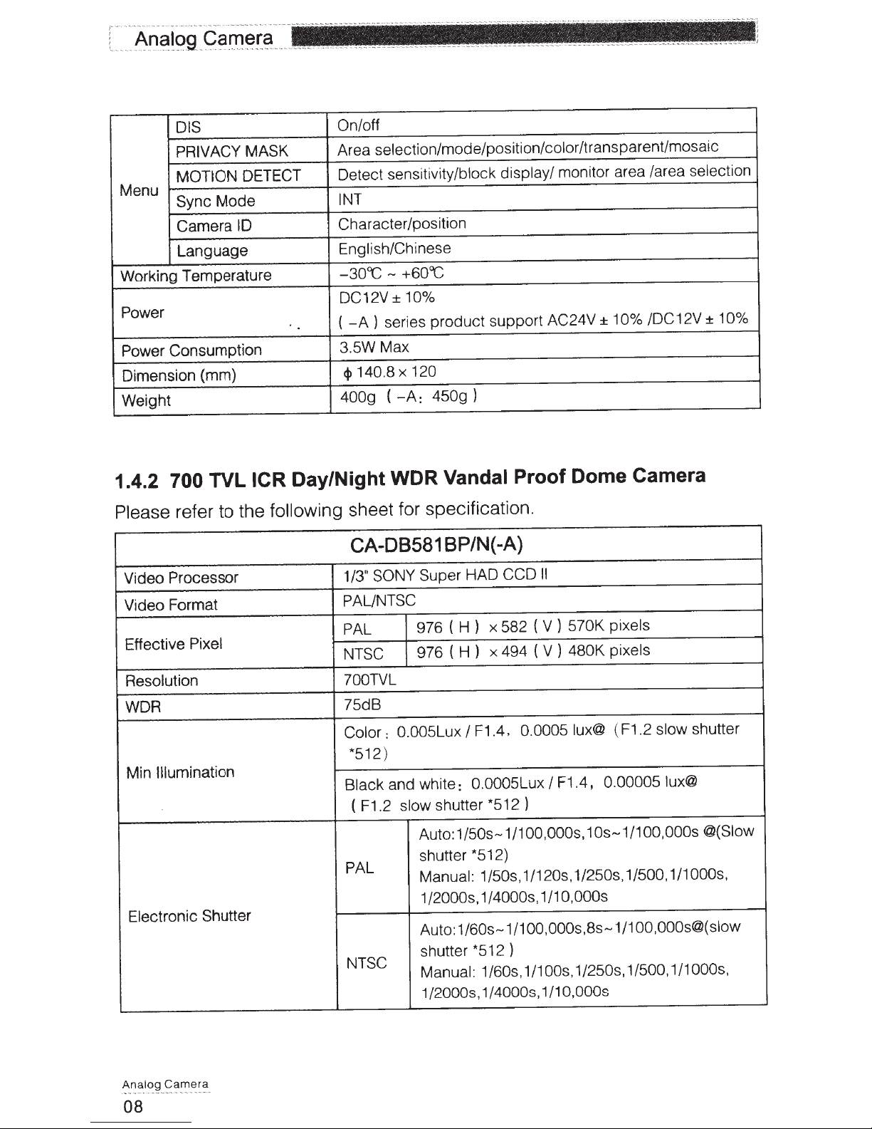
1.4.2
Please
Video
700
refer to the
Processor
Video Format
Effective
Pixel
Resolution
WDR
Illumination
Min
Electronic
TVL
Shutter
Day/Night WDR
ICR
following
sheet for specification.
CA-08581 BP/N{ -A)
/3" SONY Super HAD
1
PAUNTSC
PAL
NTSC
700TVL
75dB
Color:
*512)
Black
( F1.2
PAL
NTSC
Vandal
(H)
976
(H)
976
0.005Lux
and white:
shutter *512 )
slow
Auto:
I
0 .0005Lux
1/50s-1/1
Proof Dome Camera
II
CCD
pixels
570K
x 582 (
x 494 ( V )
F1.4.
V)
480K
F1.4,
I
lux@
0.0005
OO,OOOs,
pixels
( F1.2
0.00005 lux@
10s-1/100
slow
shutter *512)
Manual: 1/50s, 1/120s, 1/250s, 1/500, 1/1000s,
1/2000s, 1/4000s, 1/10,000s
OO,OOOs@(slow
1/1
Auto:
1/60s-1/1
OO,OOOs,Bs
-
shutter *512 )
Manual: 1/60s ,
1/1
, 1/250s, 1/500,1/1
OOs
1/2000s, 1/4000s, 1/10,000s
shutter
,000s @(Slow
,
OOOs
Ana
-·--
·
---
-·-
·
--
08
-
--
----
·-
a
Camer
log
Page 10
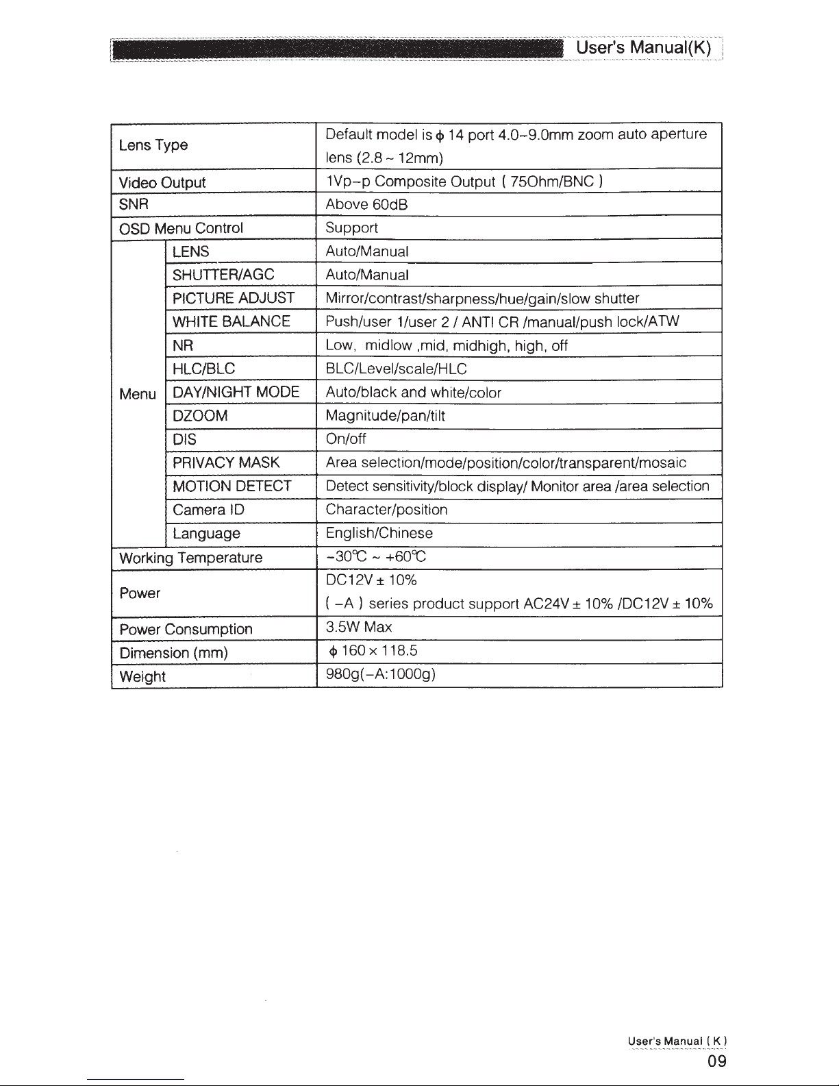
Lens Type
=:=========c
Default model is
lens
(2.8-
12mm)
<P
14 port
,_
__ , _______ .. __ . ______ .,_. __
4.0-9.0mm
User's Manuai(K) :
..
,.
....
. _
...
........
...
...
......
.........
.,_ .,_~----·--··-··-··-"
·-·-
zoom auto aperture
1
Video Output
1Vp-p
Composite Output (
SNR Above 60dB
OSD Menu Control
LENS
SHUTIER/AGC
PICTURE ADJUST
WHITE BALANCE
NR
HLC/BLC
Menu
DAY /NIGHT MODE Auto/black and white/color
DZOOM
DIS
Support
Auto/Manual
Auto/Manual
Mirror/contrast/sharpness/hue/gain/slow shutter
Push/user 1/user 2
Low, midlow ,mid, midhigh, high, off
BLC/Level/scale/HLC
Magnitude/pan/tilt
On/off
PRIVACY MASK Area selection/mode/pas
MOTION DETECT
Camera ID
Language
Working Temperature
Detect sensitivity/block display/ Monitor area /area selection
Character/position
English/Chinese
-30CC -
+60CC
DC12V ± 10%
Power
Power Consumption
Dimension (mm)
Weight
(-A)
series product support AC24V ± 10% /DC12V ± 10%
3.5W Max
<j>
160 X 118.5
-A:
980g(
1
OOOg)
I ANTI
750hm/BNC)
CR
/manual/push lock/ATW
it
ion/color /transparent/mosaic
User's
Manual ( K)
09
Page 11
..
...
~-
·-
~---
.
....
.
.....
.
..
._
...
'
~
..
..
!
11~!gg_g9
.
t-
...
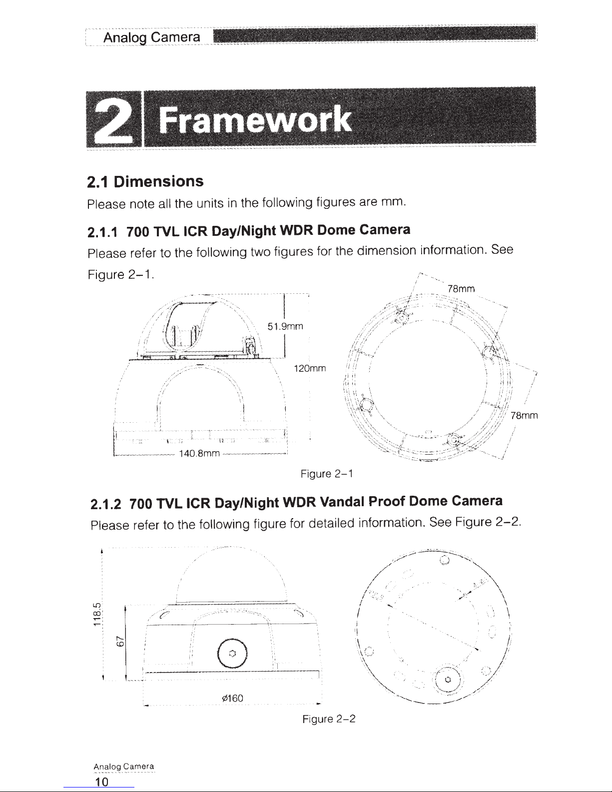
Framework
Dimensions
2.1
Please note
2.1.1
700
Please
Figure
all
TVL
refer to the following two figures for the dimension information.
.
2-1
.
..
"
~
..
.. .
-
..
..
..
...
_
.,
.,,
--
'!1~!:~
_
.
the units
Day/Night WDR Dome Camera
ICR
the following figures are mm.
in
See
2.1.2 700 TVL
Please
refer to the following figure for
Day/Night WDR
ICR
.
·-
.
·~--·"
: -
...
.
.
·-:
::·
-.~
-
:
-
-'":
.·
~
-
.._
.
;._
-
..
.
.
120mm
Figure
2-1
Vandal Proof Dome Camera
detailed
--
-
~
information. See
Figure
2-2.
-
~~~
_
t?.a!"'
.
l?9
_
f'!<i
.
~
10
¢160
'I
Figure
2-2
Page 12

2.2 Structure
. .
.
..
~~er's
_
f\11anu~I(J()
.
Please
700 TVL
refer to the
.----
ICR
Day/Night WDR
following
l
1
_,/
I
--
·'
·.J
....,.
.
---®
.
~
'(J~--;-
.
.
'i
.:
~s;.;.c;r
-·<r.:
Dome
figure for
·"---.
,__
®
~cz,
Camera
Figure
detailed information. See Figure
700 TVL
Dome
2-3
ICR
Day/Night WDR
Camera
Vandal Proof
2-3.
Please
Name
SN
Device
1
Dome
2
X-
3
Dome
4
Dome
5
Power
6
Video
7
You
refer to the
lens
camera
Y
-Z
rotation
camera
camera
input
port.
output
can
port.
connect
following
side
enclosure
module
external enclosure
pedestal
It
connects
It
is the
to
the
sheet for
to the
BNC
devices
port to output the
such as the DVR or the NVR.
detailed information.
DC
12V
power
to
input the power.
analog
video
signal.
User's
Manual
( K )
11
Page 13

--1
~
The dome camera usually mainly uses the
Important
Please
the
of
700
3.1
Mini
A
A 1 Ex
A2
make
sure
camera
TVL
dome
Pedestal
scr
pedestal
pansion
hole
ew
the
the
and
ICR
lt
bo
secure
installation
bracket.
/Night
Day
Installation
surface
WDR
in-ceiling installation.
min
can
Dome
support
Camera
the
Installation
AS
weight
3X
C elllng Or wall
mera
scre
ra
Ca
secure
w
Dome
A 3
Pedestal
A4 Pedestal
Ca_m_!l
A_r:_c:lo9
12
Figure
3-1
Page 14

8
- -
·-
User's Manual(KJ
Pedestal cable
81
exit hole
82 Side hole
B3 Pedestal secure
screw hole
1
1
C Mini dome component
Figure
3-2
\
Figure 3- 3
U
ser
's Manual ( K )
13
Page 15

0
Turn
the
camera
the
proper
lens
position
to
Important
turn
When
which
you
you have
sure
m3e
re$Uit
may
performance.
lens X-Y-Z axis.
the
touch
not
camera low
th•
in
the
pluse
lens.
Dome camera
E
enclosure
Installation
dome eamerJ
the
Push
intern<:~!
make
X-Y-Z
module.
enclosure
perfectly
it
rotation
axis
external
and pedestal
to
the
fit
Figure
3-4
E2
e~a
m
c:;a
log
~
An
14
Figure
3-5
Dome-
E1
internal
Dome-
E2
•xternal
camera
enclosure
camera
Enclosure
Page 16

Step1
User's Manuai(K)
...
...
.. ..
"'
' ''"'" ''' "''" ''• "· ·· - ··· ··
Please take the installation position map
on
paste it
the ceiling or the wall you want to install the dome camera. Dig four
holes in the installation surface and then insert four expansion bolts
If
Secure these four bolts firmly.
you want to push the cable through the
installation surface, you still need to dig a bottom cable exit hole
in
the accessories bag, and then
in
the hole.
in
the
installation surface.
Step 2
Turn the dome camera external enclosure counter clockwise and the remove.
Push the two sides of the dome camera internal enclosure (Please refer to C2
in
Figure
the dome camera internal enclosure. Please refer to Figure
3-3)
so that the hook drops from the X-Y
-Z
axis module. Remove
3-3.
Step 3
Please set the dial switch according to the information
in
chapter 2.3
Step4
Use the proper tool to open the cable exit side hole
82
refer to
refer to
in Figure
82
in Figure
3-2),
3-2)
and then draw the cable from the cable exit (Please
and fix the cable
in
in
the pedestal (Please
the pedestal cable channel.
Draw the cable port out of the cable channel side hole of the pedestal (Please
refer to the
in Figure
3-2
).
82
Step 5
Line
up
the four screw holes
ceiling (wall), then input the four secure screws
holes. Fix the screws firmly to secure the dome camera
in
the pedestal to the holes you just dug
in
the pedestal screw secure
in
the ceiling (wall).
in
the
Step 6
Turn the lens or the ring to adjust the camera to the proper direction. Adjust
X-Y -X
the
refer to the Figure
axis to turn the camera lens to the proper monitor angle. Please
3-4.
Step 7
Push the hooks (Please refer to C4
enclosure to the slot (Please refer to C5
in
Figure
in
3-3)
Figure
of two sides of the internal
3-3)
of the X-Y
User's Manual ( K )
-Z
axis to
15
Page 17

----------
--
-----
-
·
···
--------
-----.
-
~---
~!!1
.
9
..
Q9
_
A!'.l91
...
....
...
L
make the internal enclosure perfectly fit the
.
.
_
a
_
~r.
-
X-
axis. After the installation,
-Z
Y
please make sure the lens port of the internal enclosure
fit the camera lens.
is
Please
refer to Figure 3- 5 for proper adjustment if necessary.
Step 8
the pedestal.
fasten it
Turn dome camera enclosure clockwise
Step
9
to
Connect the device video output port to the terminal devices such as the
and etc. Then connect the power cable
NVS
to the device.
on
DVR,
Now you have completed the day and night high resolution dome camera
can use the terminal devices such as
installation and cable connection.
and etc to view the monitor video.
NVS
,
DVR
the
3.2 700 TVL
ICR Day/Night
You
WDR
Vandal Proof Dome Camera
Installation
Please refer to the steps listed below.
Step
1
Use the inner hexagonal wrench (provided) to loose the three inner hexagon
.
screws
the dome cover and then open the cover.
in
gure 3
Fi
-6
See
Figure
M
r~c.~
3-6
Inner Hexagonal Wrench
Inner Hexagon Screw
Camera
Analog
---
-
-
·-~
-
~
16
-.
~-
-
·-
-
-
-
·
-
-
Page 18

Step2
Use the inner hexagonal wrench (provided) to loose the three inner hexagon
screws
Figure
the dome and then remove the device
in
.
3-7
==-
~
=
r
(i
1(
-----------------
Figure
-
=oa-
----
-
--
3-7
installation
Q
·----
--
-
--
----- -
---
j)
nr
1:5
pedestal. See
] Inner Hexagonal
.
H S
' l
nner exagon crew
~
c
Wrench
Step3
Take out the installation
paste it on the ceiling or the
cable
exit and four plastic expansion bolt holes
according to the device
cable exit.
Insert the four plastic expansion bolts into the screw holes
positioning map from the accessories bag and then
to identify the installation area. Draw out the
wall
position
pedestal.
installation
the
in
Dig the four plastic expansion bolt holes and
Step4
Adjust the device installation pedestal to the proper position and then draw the
cable through the cable exit you just dug
in
ceiling (wall).
the
screw holes in the device pedestal to the four plastic expansion bolt holes
installation
the
position. Put
the four self-
tapping
screws
Line up the four
the four plastic
in
in
expansion bolts firmly.
Step 5
Adjust the device position and then line up the three inner hexagon screws of
the device to the three holes
in
installation ceiling (wall). Put
the
the three inner
User's
Manual
( K )
17
Page 19

hexagon screws to the screw holes
of the device
pedestal
and then use the
inner
hexagonal
~---------------
wrench to secure firmly.
---
--
-
--
-
Figure
--
3-8
Step6
Push the two sides of the inside enclosure
-
--·
·
--
· -
--
-----
---
-
---
C 4
Inner
Hexagon Screw
C:
S Inner
Hexagonal Wrench
of the dome to remove the tab
(02).
Loose the fixed screws
adjust the camera lens
~
-~~
j
1
'
\
"-
(04)
and then turn the
X-Y-Z
rotation
to the proper monitor angle. See Figure
----
---
--
-------
-----
-----
--
--
DJ
X-Y-Z
.-.Jj;;::::::-
- --
--
--
------
----
--
-----
lJ
2
Tab
~
/1
i]
l
//
/!
J··
··
·····
··
····
··
~
...
-
~
~:
-:-::
/;
:"
.....
/ '
···
··
L1
Dome
module
3-9
.
Rotation
Insi
de
Enclosure
(03)
Module
to
Analog
Camera
..
.
-
~
~·
--------------
18
~
-
-
Figure 3- 9
Page 20

·
-
-
~
- ·
·
·
..
User's
~
-~
-
~
--·
-
-
~
~
.• - ----- - --- .• - - --- -- ---
.•
----
~
--
..
.
---
-
·
--·
-
-
~---~-
--~~-
--
-
-
--
---
Manuai(K) ;
-·-
--
--···-1
-
~.
·
-
...
-------
--
_1
--
--
--
----
--
-- ·
Step
Put
7
the done inside
enclosure
back
the three inner hexagon screws to the
wrench to secure the screws to
complete
and then put the dome cover
holes
of the device. Use the inner
installation. See
the
Figure
back
3-10.
. Line
up
hexagonal
Figure
3-10
User's
Manual
K )
(
19
Page 21

Menu
4.1
Main Menu
THE
1•t
MENU
LENS
SHUTTER/AGC
AUTO._l
MANUAL
AUTO.-l
THE
2ND
MENU
TYPE
DC
MODE AUTO, ON, OFF
SPEED
000-255
HIGH LUMINANCE
MODE
SHUTTER+AUTO IRIS
AUTO IRIS
BRIGHTNESS
0-255
LOW LUMINANCE
AGC->SLOW
AGC->SLOW->AGC
MODE
OFF
AGC
SLOW
MANUAL.-J
PICT ADJUST
Analog
Cam
-
-
.·
~
-
-
·
era
-
--
-
----
·-
--
- ··
20
._!
BRIGHTNESS
MODE
SHUTTER
AGC
MIRROR
CONTRAST
SHARPNESS
X
0.25,
X
1.
00
X
0.50,
SHUTTER,SLOW
WDR+SHUTTER
1/53-1/10,000
6.
00-44
.
80
OFF
V-FLIP
H-FLIP
HV-FLIP
0-63
0- 15
X
0.75,
SHUTTER,
Page 22

User's Manuai(K)
ADJUST
PICT
WHITE
BALANCE
._J
MANUAL._l
ANTI CR
PUSH LOCK
PUSH
USER
USER
ATW
1._l
2._l
._l
HUE
AGC
SLOW
LEVEL
LEVEL
UP
DOWN
PRESET
B-GAIN
R-GAIN
B-GAIN
R-GAIN
SPEED
DELAY CNT
ATW FRAME
ENVIRON
MENT
0- 100
0-255
0-511
._J
._J
0- 255
0-255
0- 255
0- 255
0- 255
0-255
00
2.
X
.50-
0
X
INDOOR OUTDOOR
WDR
NR
HLC/BLC
DAY/NIGHT
AUTO
._J
._J
._J
._l
MODE
CONTRAST
VEL
LE
HLC
EL
LEV
CLIP
SCALE
BLC
BURST
DELAY CNT
NIGHT
-+
DAY
DAY
NIGHT
-+
OFF,WDR,ATR,ON
LOW,MIDLOW ,MID,
MID HIGH, HIGH
OFF,LOW,MIDLOW .
MID
MIDHIGH, HIGH
AUTO
I
OFF
I
ON
000- 255
00-15
ON
OFF
ON,OFF
000- 255
55
0-2
00
255
000-
COLOR
Use
r's
Manual
( K
21
)
Page 23

DAY/NIGHT
BN.J
DZOOM
~~
.
DIS
PRIVACY MASK
ON
OFF
._J
OFF
._J
MAGNITUDE
PAN
TILT
AREA SEL
MODE ON ,OFF
POS
COLOR
TRANSPARENT
MOSAIC
DETECT
SENSE
000-255
0000-1023
000-511
1/15-15/15
BLACK, RED,
GREEN,BLUE,
YELLOW,CYAN,
MAGENTA,
0.
00-1
ON,OFF
000-127
.
00
WHITE
MOTION
SYNC
CAMERA
LANGUAGE
CAMERA RESET
DETECT
ID
ON.-J
INT
ON+l
OFF
ENGLISH ,
CHINESE
BLOCK DISPLAY ON,OFF
DETECT AREA
AREA
MODE ON,OFF
TOP
BOTIOM
LEFT
RIGHT
SEL
1/4-4/4
00-15
00-15
00-23
00-23
·
:":~~
-
~
~
~9
-
~~
~
~
-
~~
a
-
22
Page 24

4.2 Main Interface
Press
monitor.
the menu button for 2 seconds ; you can see the
menu appear
OSD
in
the
LENS
SHUITER/AGC
PICT ADJUST
WHITE BALANCE
WD
NR
._t
NEXT
._t
EXIT
MENU
._1
._1
._1
SAVE
._t
ALL
AUTO
AUTO._~
PUSH
SYNC
CAMERAID
LANGUAGE
CAMERA RESET
MENU
MENU
HLC/BLC
DAY/N IGHT AUTO._l
DZOOM
DIS OFF
PRIVACY MASK
MOTION
BACK._~
EXIT._~
INT
OFF
ENGLISH
DETECT
._t
._t
._t
._t
ON._~
._t
NEXT
ALL
SAVE
4.3 Detailed Operation
Use the up/down button to move the cursor to the 1
button to set the corresponding parameter.
go to the
go
to
sub-menu
back to previous menu.
EXIT
._t
._t
SAVE
You
ALL
can
sr
click
BACK
if current parameter checked with
MENU, Use the left/right
the confirm button to
.J
Select
.
the BACK
Manual
User's
.J
K
(
23
I
Page 25

4.3.1
LENS
AUTO
TYPE
SPEED
Auto.J
• Type: The parameter
Mode:
•
Speed:
•
It includes
Click
auto/on/off.
left/right button
the
Manual
is the manual
It
iris lens.
4.3.2 SHUTTERIAGC
The parameter
Auto
.J
includes:
IRIS
DC
MODE
AUTO
040
RETURN
includes DCNIDEO.It
to
auto.J
AUTO sETUP
HIGH LUMINANCE
MODE
BRIGHTNESS
LOW LUMINANCE
MODE
BRIGHTNESS
RETURN
,manuai.J
set the
value.
AUTO
129
AGCAGC->SLOW
OFF
AGC,
SLOW
the direct current drive auto iris.
is
The
value
ranges from
.
IRIS
W.
>SLO
GC,
->A
.
0
to
255.
High
•
Mode: The high
•
low luminance
luminance/low
luminance
parameter
->slow->AGC.
Brightness: The high luminance parameter ranges from 0
•
the left/right button to set. The
1.00.
0.75,
0.50,
X
Camera
Analog
24
X
X
luminance:
parameter
includes AGC, off,
is the high brightness/low brightness.
It
includes
shutter+auto iris, auto iris. The
slow
shutter,
AGC->slow,
to 255. Please
low luminance
parameter
includes
0.25,
x
AGC
use
Page 26

Important
User's Manuai(K)
!
low luminance
The
is
when it is
null
in
WDR
mode.
Manuai.J
MANUAL SETUP
MODE
SHUTIER
AGC
RETURN
Mode: Right now the system supports shutter, slow
•
• Shutter: The parameter
includes 1/50, 1/120, 1/250, 1/500, 1/1000, 1/2000,
SHUTIER,SLOW SHUTIER
SHUTIER+AGC
1/53(8)
6.00(DB)
1/4000, 1/10,000.
Auto gain: The parameter
•
42.00, and
4.3.3
PICTURE
44.80.
ADJUST
Click the confirm button to
includes 6.00, 12.00, 18.00,
go
to the
sub-menu.
shutter, and WDR+shutter.
24.00, 30 .00, 36.00,
PICT
MIRROR
CONTRAST
SHARPNESS
HUE
GAIN
SLOWSHUTIER
RETURN
set the horizontal
to
is
•
Mirror:
It
• Contrast: The value
Sharpness: The value
•
Hue: The value
•
Gain: The
•
(Note: It is the
• Slow
shutter: The
ranges from 0
value ranges from
color gain.)
value
ADJUST
mirror, vertical
ranges from 0
ranges from 0
to 100. Please
to 255. Please
0
ranges from
OFF
032
009
046
122
005
mirror and
to 63. Please
Please
15.
to
use the
use the
to 511.
0
Please
horizontal+vertical
use the
use the
left/right
left/right
left/right
left/right
use the left/right
mirror.
button to set.
button to set.
button to set.
button to set.
button
to set.
User's
Manual
K )
(
25
Page 27

4.3.4 WHITE
The parameter
ATW~
Manual~
User1~
BALANCE (WB)
includes:
manual~,
MANUAL
LEVEL UP
LEVEL DOWN
PRESET
RETURN
USER1 WB
8-GAIN
R-GAIN
RETURN
WB
anti cr. push
~
~
029
050
lock,
user1
~
, user2
~
,
8-gain
•
value
R-gain:
•
value
Note:
ATW~
• ATW:
is to adjust the
It
:
ranges from 0
to adjust the red gain. Please use the
is
It
ranges from
user2
The
0
setup
ATW
SPEED
DELAY
ATW FRAME
ENVIRONMENT
RETURN
It is the auto trace white balance.
blue gain.
to 255.
to 255.
the
is
CNT
same
with
temperature according to the actual color
Please
the
239
003
1.00
X
INDOOR
use the
left/right button to set.
left/right button to set. The
user1.
camera
The
hue environments.
can
adjust
The
the color
value
• Speed:
• Delay control:
The
The
to set.
• ATW frame: The parameter
-
~~~
-
~~
_0.9_~
1
~~~
26
ranges from
value
ranges from
includes x
0 to 255.
0 to 255.Piease use the
Please
0.50,
use the left/right
x 1.50,
00,
1.
x
button to set.
left/right
x
button
2.00.
Page 28

• Environment: The parameter includes: indoor, outdoor. Please use the left/
right button to set.
Push lock
It
is
to click the OK button to lock the white balance.
Anti-color roll (ANTI CR)
Click it to enable the color roll control function.
4.3.5WDR
Mode: It includes off/WDR/ATR.
Contrast: It includes: low/midlow/mid/midhigh/high.
4.3.6 NR (NOISE REDUCE/DE-NOISE)
Click the confirm button to
Select the
on
button and then click the confirm button, you can
go
to the
sub-menu.
menu.
~:MODE
.
RETURN
I
LOW
The option includes: low/midlow/mid/midhigh/high.
4.3.7 HLC/BLC
The backlight compensation parameter includes:
HLC/BLC
HLC
LEVEL
SCALE
BLC
RETURN
OFF
000
010
OFF,
go
BLC, HLC.
to the
sub-
• BLC: This
function
environment. Please note the BLC function
•
HLC:
This function allows you to see the vivid video
• Level: The value ranges from 000 to 255. The smaller the value
the dark level of the bright section of the video
allows
you
to
see the
vivid
is
null
video
in
in
the highlight environment.
WDR
in
and
the
backlight
ATR
is,
the higher
is.
User's
mode.
Manual ( K)
27
Page 29

A.nalog
• Scale:
(;~mera
the exposure level.
is
It
__
The value ranges from
000
to
The higher
015.
value is, the higher the bright level of the
the
4.3.8
The parameter
DAY/NIGHT
includes:
auto
.-1,
trigger.
Auto
•
• Delay control:
.-1
DAY/NIGHT MODE
BURST
DEALY
DAY
NIGHT- DAY
RETURN
Burst: The parameter includes on, off.
The value
button to
set
CNT
NIGHT
--+
ranges from
whole
video
color, black and white
ON
003
001
004
to 255. Please
000
is.
,
.-1
use the
and
external-
left/right
is to set the minimum parameter to switch from the day mode
• Day-night:
to the night mode. The
It
value
button to set.
to set the maximum parameter to switch from the night mode
is
Night-day:
•
It
to the day mode. The value
button to
set
Note:
smaller
day-night
In
black and white mode.
the
to
for
hard
If the
in
system
night-day mode larger and the
mode,
camera
the
switches back and forth
the
sWitch
to
ranges from
ranges from
value,
the
night-day
In
color.
the
to
when
value
to 255.
000
to 255.
000
hard for the camera to switch
the
and
mode
Here
in
, the larger the
recommend
we
€Ire
you
the day-night
Please
using,
Please use the left/ri
use the
value
the
please
default
set
left/right
and
is,
value.
value
the
mode smaller.
ght
the
Camera
og
Anal
h···-- ··-
····
··
..
·-
-·
··
-·
·
28
Page 30

4.3.9 DIGITAL ZOOM
' ' ' '
. .
••
'--
._
,
..
.• . , , •
~e
_
y
.• ,
"-'"
"
'"
" " "'
•oH"'"
•
·"'
'•
'
'••
~•·
-
---
·•,
·
•
· ·
•
·
•
•'
~-
~IJ~L
_
~
_
~a.!.l
--
~~s
-
'' 0 0
"•
' " " " '
'"
•'
]
MAG
PAN
TILT
RETURN
Magnitude: The value
•
• Pan:The value
value
• Tilt:
4.3.1
The
Note:
This
0 PRIVACY
function
ranges from
ranges from
MASK
ranges from 000
when
null
is
The parameter includes on, off
Select
the
button and then
on
PRIVACY
AREA
MODE
POSITION
COLOR
TRANP
MOSAIC
RE
TURN
click
SEL
000
512
256
to 255.
to 1023.
000
to 511.
000
on.
the
digital
image stabilization function
is
.J
the confirm button, you can go to the sub-menu.
1/15
OFF
• Area selection: The value
button to set.
System
right button to set.
Mode; It includes on/off.
•
• Position:
Please use the middle button to set the point and then use the up/
down/left/right to set the coordinates.
• Color: The option includes: black/red/green/blue/yellow/cyan/magenta/white.
Please
use the left/right button to set.
• Transparent: The parameter includes:
Mosaic: The parameter includes on, off.
•
ranges from 1/15 to 15/15.
max supports 15 areas.
can set the
It
0.00, 0.50, 0.75,
Please use the left/right
can use the up/down/left/
You
non-rectangle
1.00.
and
User's Manual (
area.
K)
29
Page 31

..
~
-
·
·-
.....
..........
--
1\J'l()J()
, ,
..
.
~
'
. -
.....
..
,
.•
. -.. . -- -· "
..
.
_g
9C3'!1~f(3
.
-
4.3.11
The parameter includes:
MOTION DETECT
on/off~
.
Select the on button and then click the confirm button, you can
menu.
MOTION
DETECT
BLOCK
MONITOR
AREA
TOP
BOTIOM
LEFT
RIGHT
RETURN
• Detect sensitivity: The value ranges from 000 to
DETECT
SENSE
DISP
AREA~
SEL
111
OFF
ON
1/4
000
000
000
000
127.
Please use the lefVright
button to set.
go
to the
sub-
~
• Block: display: The parameter includes on, set
. Click the set button;
you can use the direction buttons to set the area to display the block.
• Monitor area: The parameter includes on, off.
• Area selection: The value ranges from 1/4 to 4/4. Please use the left/right
button to set. System max supports 4 areas. You can use the up/down/left/
right button to set.
to
• Top: The value ranges from 000
• Bottom: The value ranges from 000
015. Please use the left/right button to set.
to
015. Please use the lefVright button
to
• Left: The value ranges from 000 to 013. Please use the left/right button to se
• Right: The value ranges from 000 to 013. Please use the left/right button to set.
MC,)ti;
'thrs
ft.JI'lctidn
islf')v~fi9
when
.
the
·
digrtaf
image
stab.ilization
rOtS)
functionis
_
on.
4.3.12 SYNC MODE
The system supports INT setup.
set.
t.
Analog
Camera
"·--~-"-
~
... -,
,-
..
-·····
-~
.•. , ....• , .
..
30
Page 32

4.3.13 CAMERA
ID
The parameter includes
Select the on button and then click the confirm button, you can
on
...1,
off.
go
to the
submenu. Please use the direction buttons to select the character or the function
and then click the confirm button to select.
CAMERA
00001
ABCDEFGHIJKLMNOPORSTUV
W X Y Z 0 1 2 3 4
! l _·,
__. i 1 CLR
RETURN
~
i l: Select the character you want to modify.
CLR:
POS
Clear current character.
...1:
Select it to go to the camera mask position interface.
10
56
¥:
; < = >?@r·. x
POS~
7 8 9
-!
+I
" #
$%
& '
4.3.14 LANGUAGE
The parameter includes: English, Japanese and etc. The default setup
is
English.
4.3.15 CAMERA RESET
Please select the reset item and then click the confirm button to restore the
factory default setup.
4.3.16 OTHERS
Next : Click it to
Back: click it to return to the previous menu.
Return : click it to exit the menu setup interface.
SAVE
ALL: Click it to save current setup.
Important
After you completed the setup, please click the "SAVE ALL" button to save
current setup and then exit the menu. It
the power failure.
go
to the
sub-menu.
is
to guarantee the camera setup after
User's Manual ( K )
31
Page 33

Appendix Toxic or Hazardous Materials
or
Elements
Toxic
or
Hazardous
Materials
or
Elements
Component
Name
Circuit Board Component
Device Construction
Material
Wire
and
Cable
Packing Components
Accessories
0:
Indicates that the concentration of the hazardous substance
in
materials
X:
Indicates that the concentration
homogeneous materials
the parts is below the relevant threshold
in
Pb
0 0 0
0 0
0 0
Hg
Cd
Cr
VI
0 0
0 0
0 0 0 0
0 0 0 0
0 0 0
of
the SJ{T11363-2006 standard.
of
the hazardous substance of at least one of all
the parts is above the relevant threshold of the
0 0 0
2006 standard. During the environmental-friendly use period (EFUP) period, the toxic
or hazardous substance
elements contained
in
products will not leak or mutate so
or
that the use of these (substances or elements) will not result
environmental pollution, any bodily
inJury
or damage to any assets. The consumer
not authorized to process such kind of substances or elements, please return to the
corresponding local authorities to process according to your local government statutes.
PBB
PBDE
0
0 0
in
all homogeneous
SJ(f11363-
in
any severe
0
0
is
This manual is for reference only. Slight difference
interface.
All the
designs
and software here are subject to
notice.
If there is any uncertainty or controversy, please refer to the final explanation
of
us.
Please visit our website or contact
information.
Analog
Camera
......
~. " ·
~
.........
~
..
•..
.
···~
....
·
~-
..
··
32
Note
your
local service engineer for more
. . ..
..
-...
..
.............
..........
change
... ........
may
be
without prior written
....................................
found in the user
_....
.....
....
...
.......
........
.....
.. .
..
..
......
....
...
......
if
ll
il
l!
l:
ll
;,
J:
i i
l1
i!
:;
H
!I
ii
u
"
"
il
"
"
II
H
i!
il
ll
~
I
ii
..
.......
.....
.))
Page 34

N
C..J1
co
0
()1
w
r..o
Page 35

Screw
Installation
Hole
Day/Night
Extra
High
Resolution
Dome
Camera
Installation
Positioning,ly1ap .
Please
open
the
self-adhesives
label
arid
then
adjust
to
the
proper
position, finally
paste
in
the
installation
surface.
Screw
Installation
Hole
Page 36

POWERED BY
ClearView
A Clear Choice
ClearView CCTV products are professional quality equipment, and we stand behind our products with a 7 Year Warranty.
ClearView CCTV will replace, or at its sole discretion repair without charge, any DVR (Digital Video Recorder),
NVR (Network Video Recorder) Camera or accessory proved defective in material, workmanship or operation for a period of
If during the warranty period, we cannot repair your product, we will replace the product with a working product of the
seven (7) years, subject to warranty conditions and exceptions below.
same model, or if the same model is not available, with a comparable product.
Seven (7) Year Warranty
Conditions & Exceptions:
1. Dated proof of purchase with covered unit serial numbers is required for warranty service.
Please include a copy of your receipt with your return.
2. All goods requiring warranty repair require acquiring an authorized Return Materials Authorization (RMA) number.
RMA numbers can only be issued by ClearView CCTV technical representatives via email (support@clearviewcctv.com)
or by calling the support line at (786) 454-9372.
3. Service returns must have the issued RMA number displayed on the return shipment carton or label.
Returns received without an RMA number visible will be refused and returned to the sender unopened.
4. Service returns must be sent prepaid via a package or freight method that provides a tracking number, to:
ClearView CCTV Inc.
RMA# (use your issued RMA number)
3010 N Andrews Ave EXT
Pompano Beach, FL 33064
5. ClearView CCTV Inc assumes no risk and shall be subject to no liability for damages or loss resulting from the specic use or application
made of the Products. ClearView CCTV’s liability for any claim, whether based on breach of contract, negligence, infringement of any
rights of any party or product liability, relating to the Products shall not exceed the price paid to ClearView CCTV Inc for such Products
or the published MSRP, whichever is less.
6. In no event will ClearView CCTV Inc be liable for any special, incidental or consequential damages (including loss of use, loss of prot
and claims of third parties) however caused, whether by the negligence of ClearView CCTV Inc or otherwise.
7. For warranty repaired or replaced products, ClearView CCTV Inc will warrant all replacement parts and repairs for the remainder of the
original warranty, or 90 days from the date of ClearView CCTV repair/replacement return shipment, whichever is longer.
8. Service and warranty repairs are prorated from the end user date of purchase. For Three (3) years (36 months) after purchase ClearView
covers 100% of replacement or repair costs. After 3 years (36 months), replacement or repair value will prorate for normal wear & tear
by 2.04% per month from date of purchase through the end of warranty period. Warranty is non-transferrable.
9. Repairs made necessary by reason of misuse, alteration, or accident, or cosmetic damage such as nish fading or scratches & scus are
not covered under this warranty.
10. This warranty is void if the product defect is caused by:
• Cracks and/or leaks caused as a result of abnormal normal wear and/or accident, vandalism or abuse;
• Use with non-ClearView CCTV Inc hardware products or software not licensed by ClearView CCTV Inc
(including but not limited to adaptors and power supply sources) or which are otherwise not compatible;
• Unauthorized modication or tampering; opening, disassembly, attempted repair, modied,
or alteration by other than ClearView CCTV Inc authorized repair centers.
• Damage by Acts of God, lighting, power surge, misuse, abuse, over exposure to the sun or elements, negligence, accident,
wear and tear, mishandling, misapplication, intrusion of or exposure to liquids, or other causes unrelated to
defective materials or workmanship;
• If serial number is defaced, altered, or removed;
• Malicious software, programs, data, viruses, or les;
• Use not in accordance with the accompanying documentation and use instructions; or
The above warranty provides the Dealer and consumer with specic legal rights. The Dealer or consumer may also have
additional rights, which are subject to variation from state to state.
 Loading...