

Page 1
Page 2
Page 3

Page 4
Page 5

Page 6

Page 7
Page 8
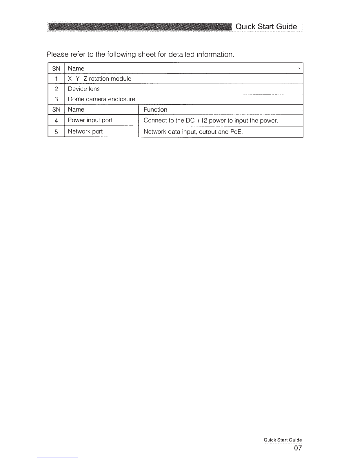
Page 9
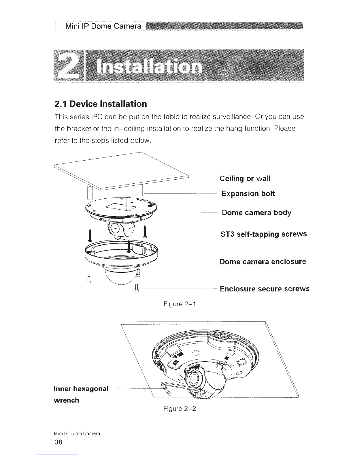
Page 10
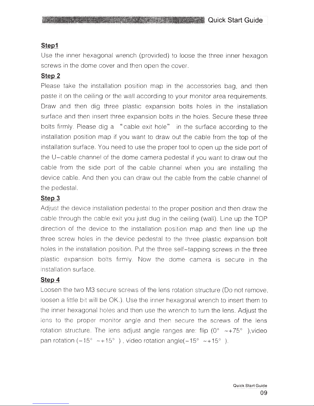
Page 11
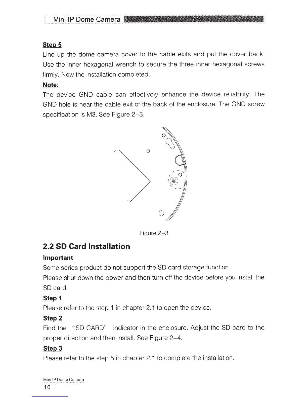
Page 12

Page 13
Page 14
Page 15

Page 16

Page 17
Page 18
Page 19
Page 20
Page 21

Page 22
Page 23

HD IR Waterproof Fixed IP Dome Camera
Quick Start Guide
Version 1.0.0
Page 24

Welcome
Thank you for purchasing our IP camera!
This quick start guide is designed to be a reference tool for your system.
Please keep this start guide well for future reference.
Please open the accessory bag to check the items one by one in accordance with the list below.
Contact your local retailer ASAP if something is missing or damaged in the bag.
Before your operation please read the following instructions carefully.
1᧪Electrical safety
All installation and operation here should conform to your local electrical safety codes.
The power shall conform to the requirement in the SELV (Safety Extra Low Voltage) and the Limited
power source is rated 12V DC in the IEC60950-1.This series product supports PoE too. Please note:
Do not connect these two power supplying sources to the device at the same time; it may result
in device damage!
We assume no liability or responsibility for all the fires or electrical shock caused by improper handling
or installation.
We are not liable for any problems caused by unauthorized modification or attempted repair.
2᧪Transportation security
Heavy stress, violent vibration or water splash are not allowed during transportation, storage and
installation.
3᧪Installation
Do not apply power to the camera before completing installation.
Please install the proper power cut-off device during the installation connection.
Always follow the instruction guide the manufacturer recommended.
4᧪Qualified engineers needed
All the examination and repair work should be done by the qualified service engineers.
We are not liable for any problems caused by unauthorized modifications or attempted repair.
5᧪Environment
This series IP camera should be installed in a cool, dry place away from direct sunlight, inflammable,
explosive substances and etc.
Please keep it away from the electromagnetic radiation object and environment.
Please make sure the CCD (CMOS) component is out of the radiation of the laser beam device.
Otherwise it may result in CCD (CMOS) optical component damage.
Please keep the sound ventilation.
Do not allow the water and other liquid falling into the camera.
i
Page 25

Thunder-proof device is recommended to be adopted to better prevent thunder.
The grounding studs of the product are recommended to be grounded to further enhance the reliability
of the camera.
6. Daily Maintenance
Please shut down the device and then unplug the power cable before you begin daily maintenance
work.
Do not touch the CCD (CMOS) optic component. You can use the blower to clean the dust on the lens
surface.
Always use the dry soft cloth to clean the device. If there is too much dust, please use the water to
dilute the mild detergent first and then use it to clean the device. Finally use the dry cloth to clean the
device.
Please put the dustproof cap to protect the CCD (CMOS) component when you do not use the camera.
7. Accessories
Be sure to use all the accessories recommended by manufacturer.
Before installation, please open the package and check all the components are included.
Contact your local retailer ASAP if something is broken in your package.
Accessory Name Amount
IPC Unit 1
Quick Start Guide 1
CD 1
Installation Accessories Bag 1
ii
Page 26

Table of Contents
6WUXFWXUH ...................................................................................................................................... 1
&RPSRQHQWV..................................................................................................................1
)UDPHZRUNDQG'LPHQVLRQ.........................................................................................1
'HYLFH,QVWDOODWLRQ ......................................................................................................................3
,QVWDOODWLRQ6WHSV ..........................................................................................................3
5HVWRUH)DFWRU\'HIDXOW6HWXS,QWURGXFWLRQ.............................................................5
4XLFN&RQILJXUDWLRQ7RRO........................................................................................................... 6
2YHUYLHZ........................................................................................................................ 6
2SHUDWLRQ ....................................................................................................................... 6
:HE2SHUDWLRQ............................................................................................................................ 9
1HWZRUN&RQQHFWLRQ..................................................................................................... 9
/RJLQDQG/RJRXW.......................................................................................................... 9
)$4 ............................................................................................................................................12
$SSHQGL[7R[LFRU+D]DUGRXV0DWHULDOVRU(OHPHQWV ............................................................... 13
iii
Page 27
6WUXFWXUH
&RPSRQHQWV
)UDPHZRUNDQG'LPHQVLRQ
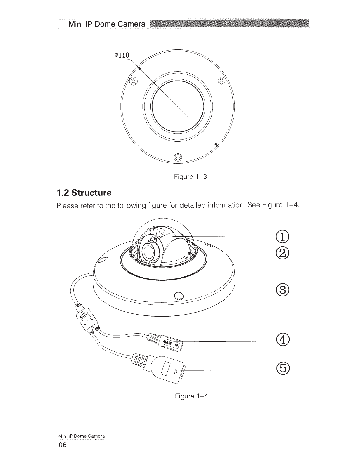
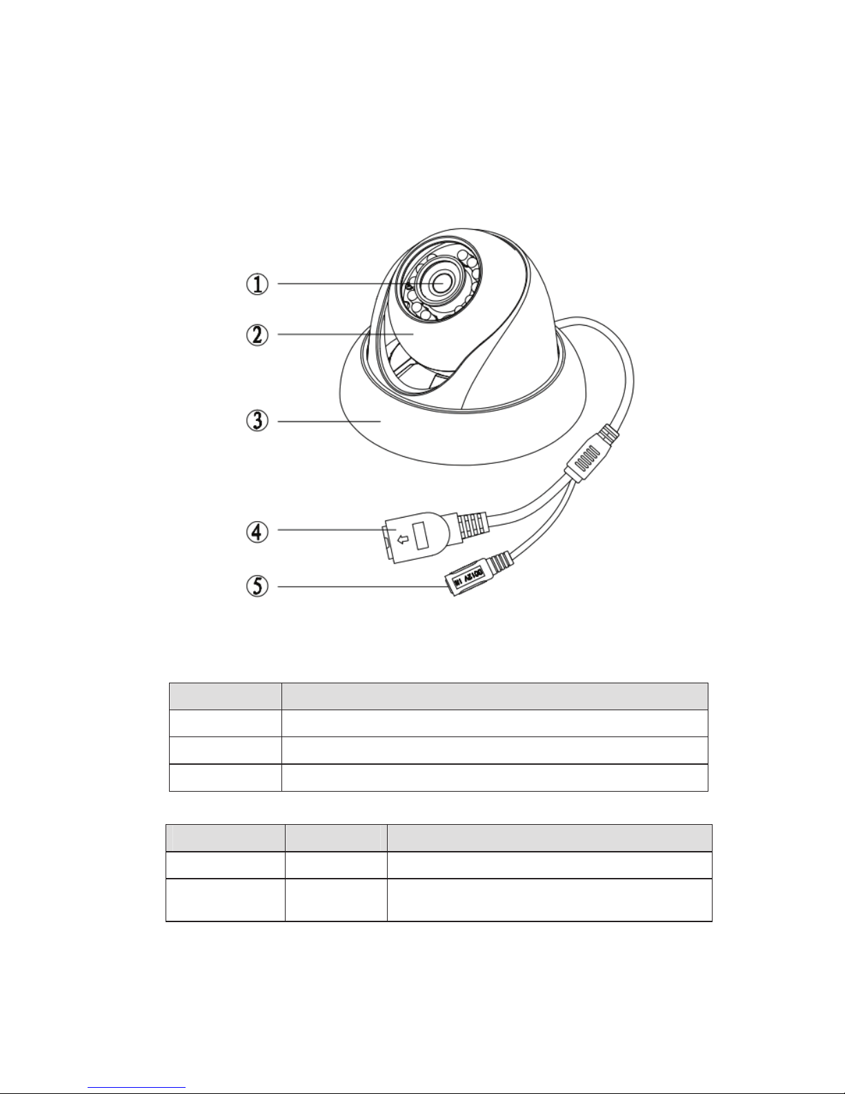
You can refer to the following figure for multiple-function combination cable information. See Figure
1-1
.
Please refer to the following sheet for detailed information.
Component Component Name
Component 1 Device lens
Component 2 Dome body
Component 3 Dome enclosure
Port Name Function Note
Port 4 Network port Connect to standard Ethernet cable.
Port 5
DC 12V
power
Power input port. Input DC 12V.
Figure 1-1
1
Page 28

Please refer to the following two figures for dimension information. The unit is mm. See Figure 1-2 and
Figure 1-3.
Figure 1-2
Figure 1-3
2
Page 29

'HYLFH,QVWDOODWLRQ
,QVWDOODWLRQ6WHSV
Important
Before the installation, please make sure the installation environments can at least support 3x weight
of the camera.
Please follow the steps listed below to install the device. Please refer to Figure 2-1 for reference.
Step 1
Turn clockwise to remove the decoration ring from the snap joints.
Step 2
Please take the installation position map in the accessories bag, and then paste it on the ceiling or the
wall according to your monitor area requirements. Draw and then dig three plastic expansion bolts
holes in the installation surface and then insert three expansion bolts in the holes. Secure these three
bolts firmly. Please draw the cable out from the cable exit when you install the device.
Step 3
Adjust the device installation pedestal to the proper position and then line up the three screw holes in
the device pedestal to the three plastic expansion bolt holes in the installation position. Put the three
self-tapping screws in the three plastic expansion bolts firmly. Loosen the M3X8 cross recessed pan
head slot screw of the pedestal to unfasten the preforming. (Do not remove, loosen a little bit will be
OK.). Adjust the lens to the proper monitor angle and then use the original preforming to turn the M3X8
cross recessed pan head slot screw back.
Step4
Line up the three spigots of the decoration ring to the jags from the bottom to the top and then turn
clockwise until you hear a clear sound ”KA”. Now the installation is complete.
Important
Please pay attention to the dome camera direction when you are installing. Please refer to the
following figure for detailed information. See Figure 2-2.
Figure 2-1
3
Page 30
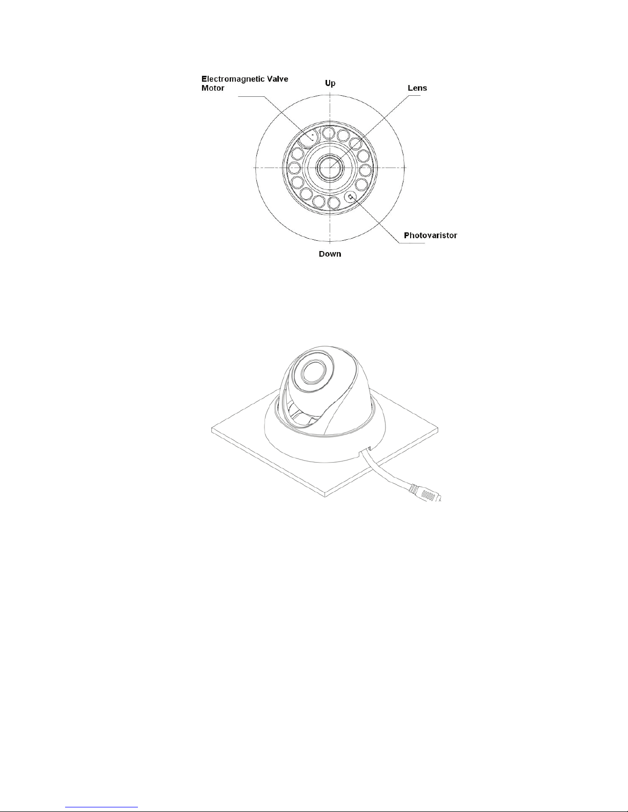
Figure 2-2
Note
This series product supports two cable exits. One is from the bottom and the other is from the side.
Please refer to the following figure for cable exit from the side information.
Figure 2-3
Please earth the GND port of the device to enhance the device reliability. The GND port is near the
cable exit port on the rear of the dome. The GND screw uses the M2X5 pan screw.
4
Page 31
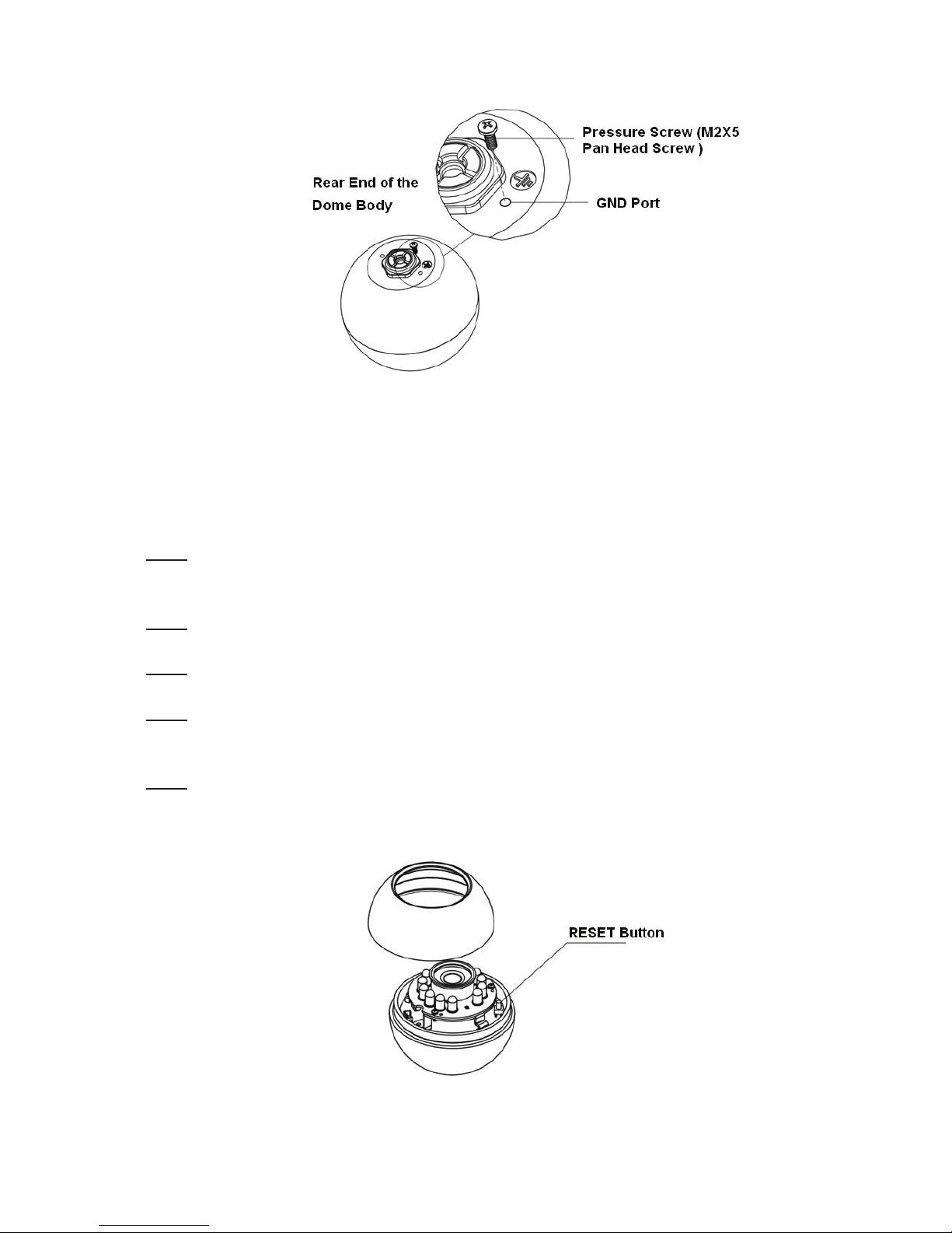
Figure 2-4
5HVWRUH)DFWRU\'HIDXOW6HWXS,QWURGXFWLRQ
Important
Please use RESET button when device is running.
Step1
Please refer to step1 and step2 in chapter 2.1to loose the dome body. Push a little bit; you can take
the dome body from the gland cover.
Step2
Take the dome body out and then turn the top cover hard to remove.
Step3
Slightly press the RESET button to complete the reset function. See Figure 2-5.
Step4
Turn the top cover back to the original position. Please make sure it reaches the original position,
otherwise it may result in water leakage!
Step5
Put the dome back to the gland cover. Please refer to step4 in chapter 2.1 to install the decoration ring
back.
Figure 2-5
5
Page 32
4XLFN&RQILJXUDWLRQ7RRO
2YHUYLHZ
2SHUDWLRQ
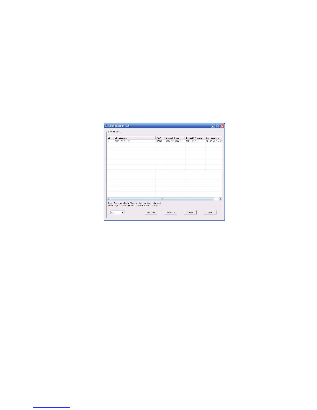
Quick configuration tool can search current IP address, modify IP address. At the same time, you can
use it to upgrade the device.
Please note the tool only applies to the IP addresses in the same segment.
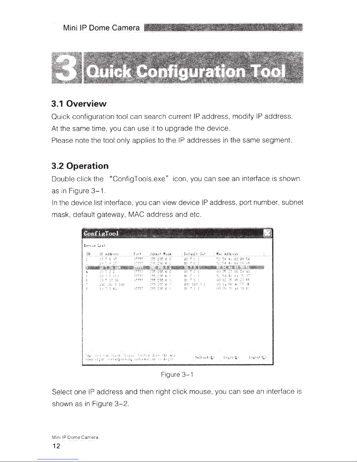
Double click the ĀConfigTools.exeāicon, you can see an interface is shown as in Figure 3-1.
In the device list interface, you can view device IP address, port number, subnet mask, default
gateway, MAC address and etc.
Figure 3-1
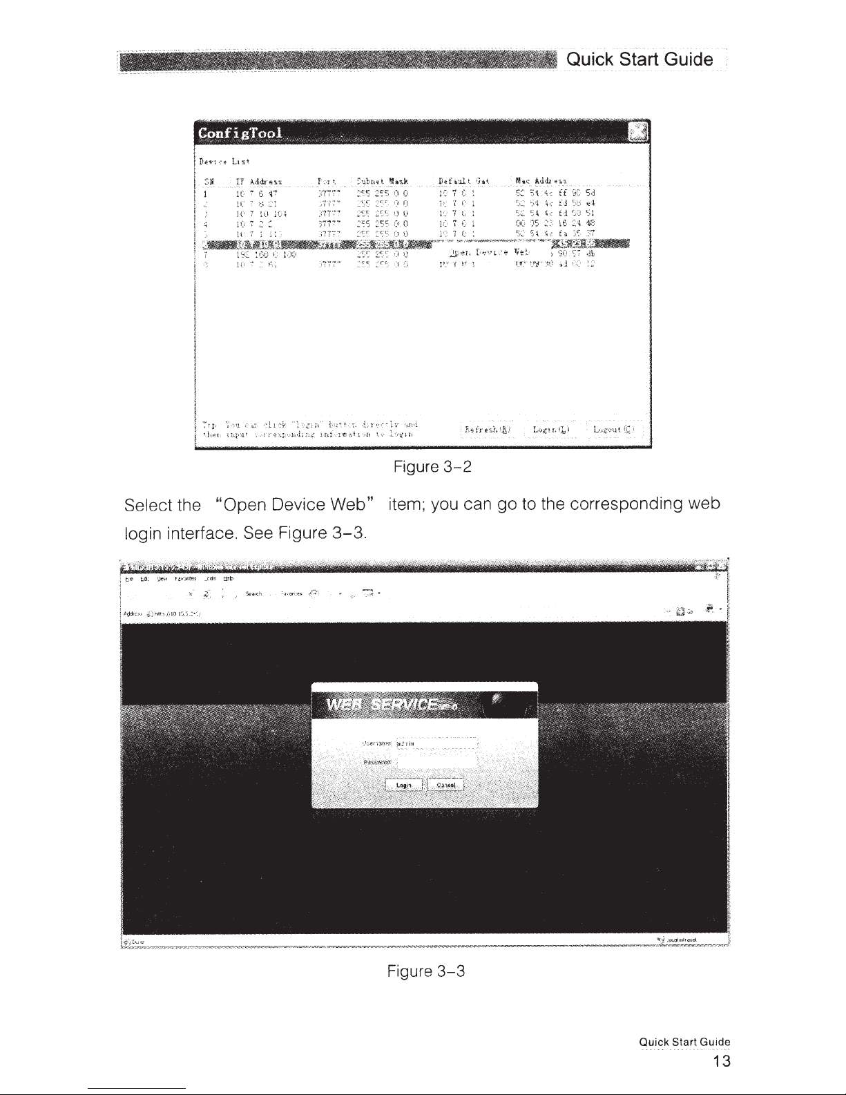
Select one IP address and then right click mouse, you can see an interface is shown as in Figure 3-2.
Note:
You can set the IP address, subnet mask and gateway for the IPC and PC. Please note IPC IP
address and PC IP address shall be in the same network segment if there is no router. IPC default IP
address is 192.168.1.108. If there is a router, please set the corresponding gateway and subnet mask.
The factory default user name is admin and password is admin. For security reasons, please modify
your password after you first login.
For detailed WEB operation, please refer to the IPC Web Operation Manual in the resource CD.
6
Page 33
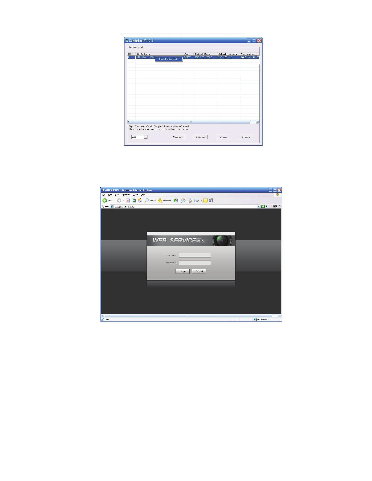
Figure 3-2
Select the “Open Device Web” item; you can go to the corresponding web login interface. See Figure
3-3.
If you want to modify the device IP address without logging in the device web interface, you can go to
the configuration tool main interface to set.
In the configuration tool search interface (Figure 3-1), please select a device IP address and then
double click it to open the login interface. Or you can select an IP address and then click the Login
button to go to the login interface. See Figure 3-4.
In Figure 3-4, you can view device IP address, user name, password and port. Please modify the
corresponding information to login.
Please note the port information here shall be identical with the port value you set in TCP port in Web
Network interface. Otherwise, you can not login the device.
If you are use device background upgrade port 3800 to login, other setups are all invalid.
Figure 3-3
7
Page 34
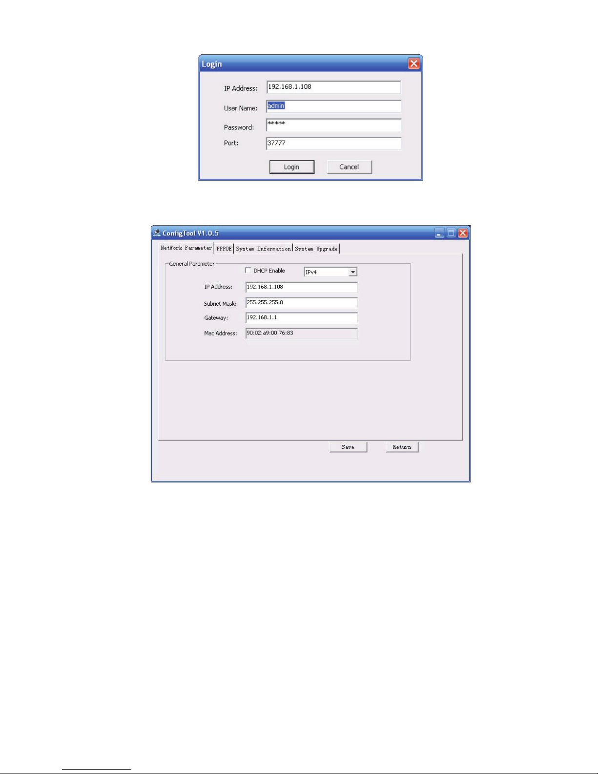
Figure 3-4
After you logged in, the configuration tool main interface is shown as below. See Figure 3-5.
For detailed information and operation instruction of the quick configuration tool, please refer
to the Quick Configuration Tool User’s Manual included in the resources CD.
Figure 3-5
8
Page 35
:HE2SHUDWLRQ
1HWZRUN&RQQHFWLRQ
/RJLQDQG/RJRXW
This series IPC product support the Web access and management via PC.
Web includes several modules includes monitor channel preview, system configuration, alarm and etc.
Please follow the steps listed below for network connection.
z Make sure the IPC has connected to the network properly.
z Please set the IP address, subnet mask and gateway of the PC and the IPC respectively. IPC
default IP address is 192.168.1.108. Subnet mask is 255.255.255.0. Gateway is 192.168.1.1
z Use order ping ***.***.***.***(* IP camera address) to check connection is OK or not.
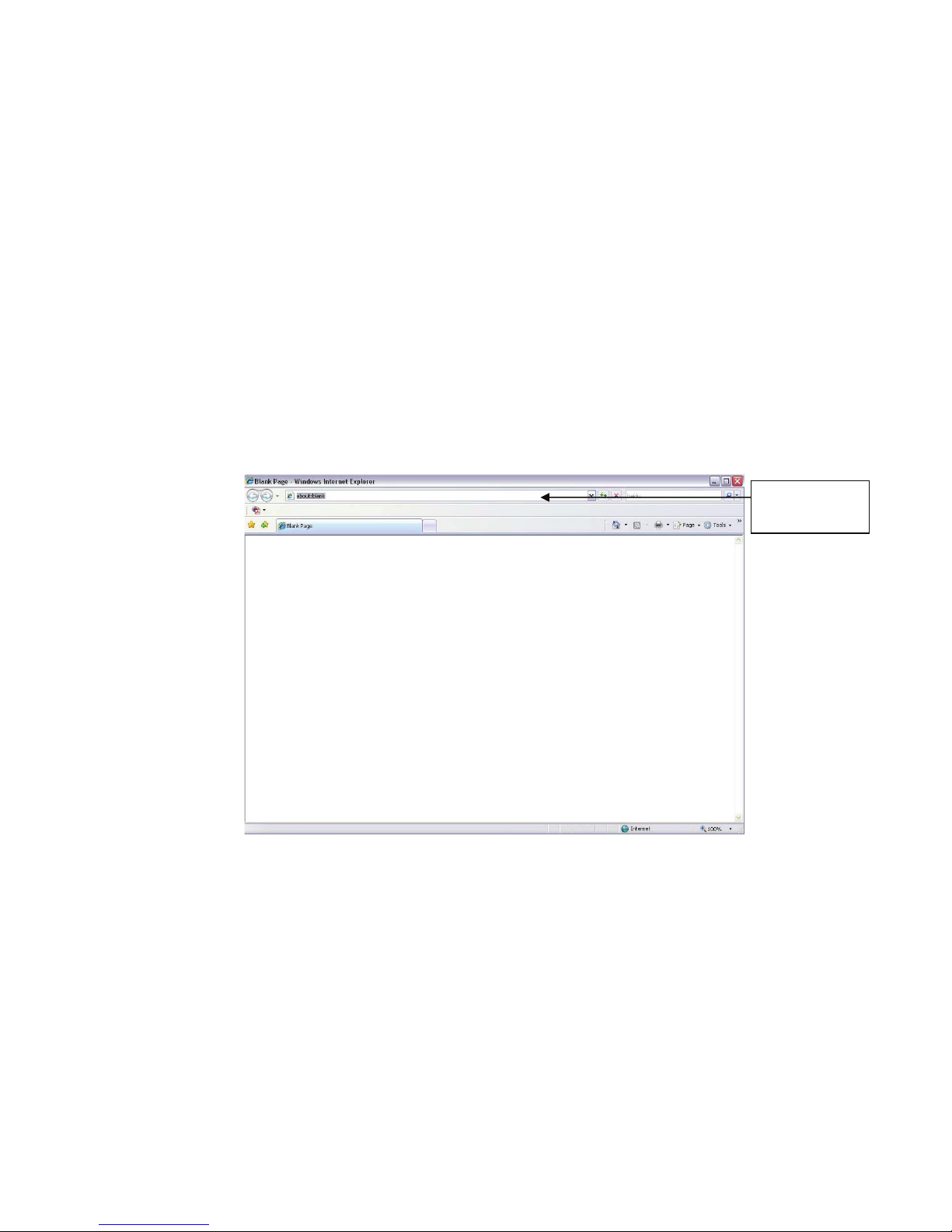
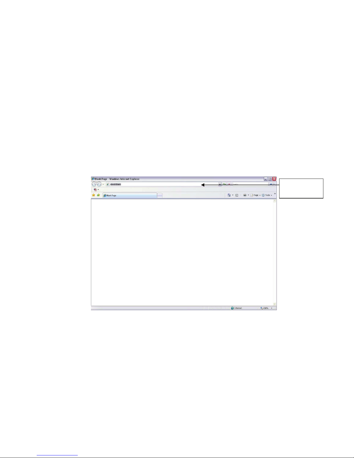
Open IE and input IP camera address in the address bar.
For example, if your camera IP is 192.168.1.108, then please input http:// 192.168.1.108 in IE address
bar. See Figure 4-1.
Input your IP
address here
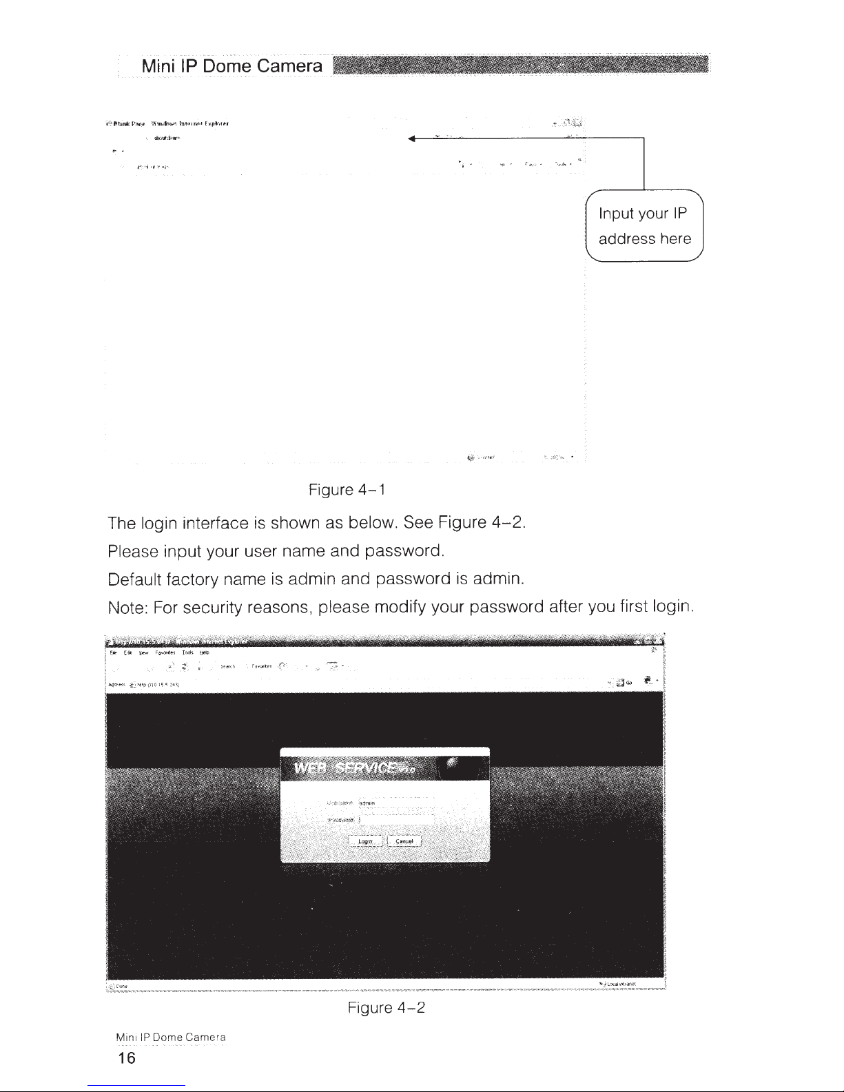
The login interface is shown as below. See Figure 4-2.
Please input your user name and password.
Default factory name is admin and password is admin.
Note: For security reasons, please modify your password after you first login.
Figure 4-1
9
Page 36
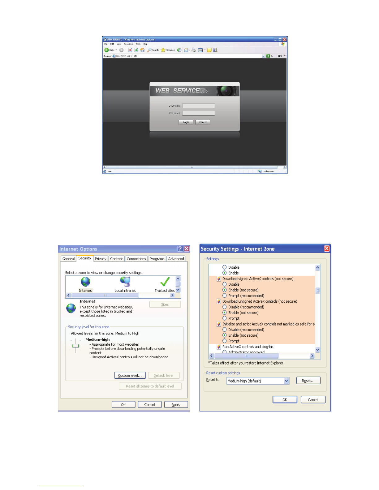
Figure 4-2
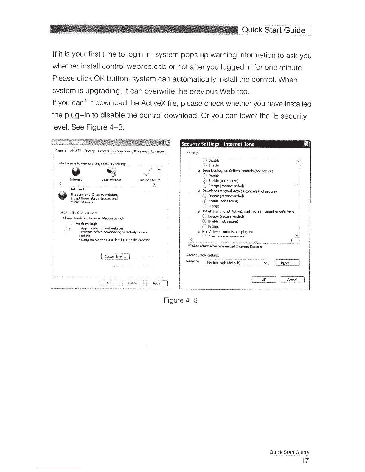
If it is your first time to login in, system pops up warning information to ask you whether install control
webrec.cab
automatically install the control. When system is upgrading, it can overwrite the previous Web too.
If you can’t download the ActiveX file, please check whether you have installed the plug-in to disable
the control download. Or you can lower the IE security level. See Figure 4-3.
or not after you logged in for one minute. Please click OK button, system can
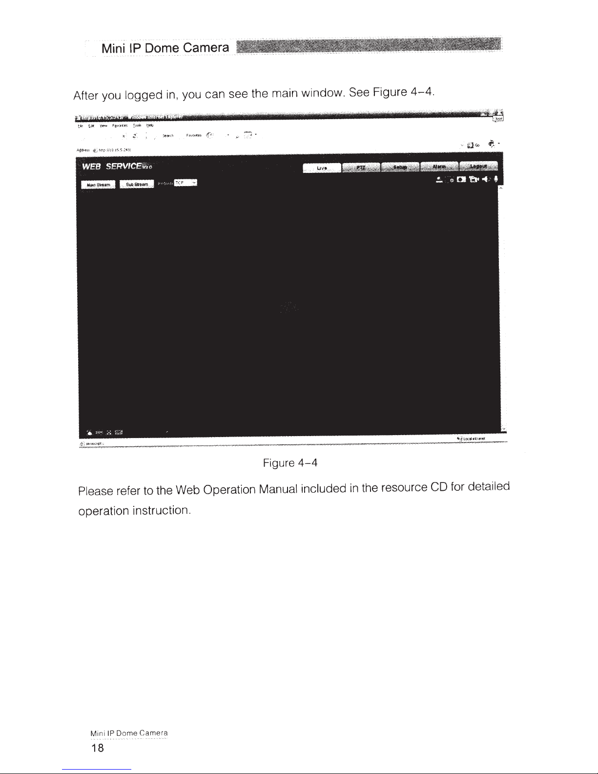
After you logged in, you can see the main window. See Figure 4-4.
Figure 4-3
10
Page 37
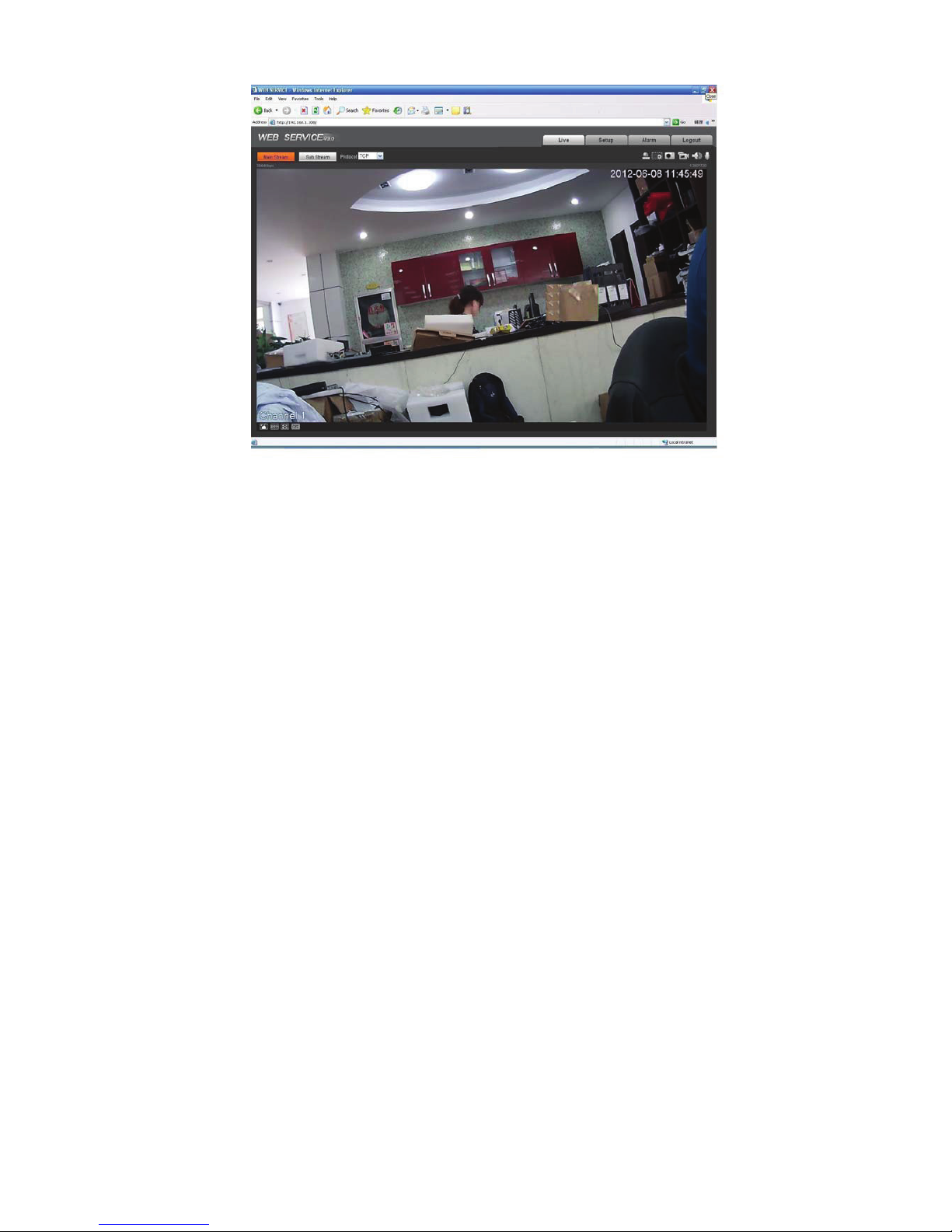
Figure 4-4
Please refer to the Web Operation Manual included in the resource CD for detailed operation
instruction.
11
Page 38

)$4
Bug
I can not boot up
the device or
operate properly.
The water leakage
occurred.
IR video is poor. Do not use the proper supplying power. The IR light can not turn on
I can not upgrade
the device via
network.
I can not login the
client-end or the
WEB.
Please click RESET button for at least five seconds to restore
factory default setup.
The unauthorized front or rear cap remove many result in water
leakage.
The glass front cap has sustained heavy push or strike.
The waterproof plug of the rear cap becomes loosen.
completely.
The object is out of the IR distance range of current device.
IR-CUT does not turn to the night mode. The photosensitive chip of
the front-end can not sense the IR light.
When network upgrade operation failed, you can use port 3800 to
continue upgrade.
For Windows OS 98 or Windows ME user, if you can not install the
client-end or can not view after the installation. We recommend the
win2000sp4 OS or install the client-end of the low version.
The Active X control is blocked.
The display card version shall be dx8.1 or higher.
Network connection error occurred.
Invalid network setup.
Invalid user name or password.
I can not play the
download file.
To guarantee
setup update
Power adapter
There is no player.
There is no DX8.1 or higher.
For the MEDIA PLAYER, there shall be Div X503Bundle.exe plugin
if you play the .AVI file.
For Windows XP user, you need to install the plugin
DivX503Bundle.exe and ffdsho-2004 1012.exe.
After you modified the important setup, please reboot the device via
the software to make sure the setup has been updated to the
storage medium.
The general power adapter can work ranging from 0ć to 40 ć. The
device may result in unstable power supply when the temperature
exceeds the working temperature.
Please replace an industry-level power adapter if you are using in
the harsh environments.
12
Page 39

$SSHQGL[7R[LFRU+D]DUGRXV0DWHULDOVRU(OHPHQWV
Component
Name
Circuit Board
Component
Device
Construction
Material
Wire and Cable
Packing
Components
Accessories ż ż ż ż ż ż
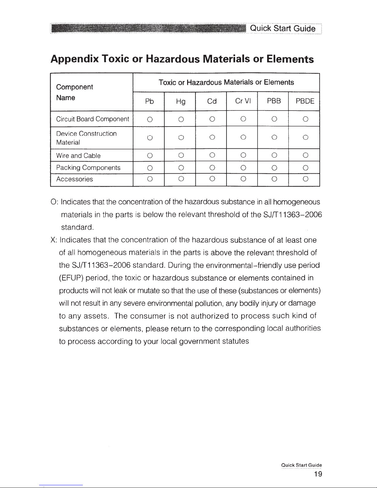
O: Indicates that the concentration of the hazardous substance in all homogeneous materials in the
parts is below the relevant threshold of the SJ/T11363-2006 standard.
X: Indicates that the concentration of the hazardous substance of at least one of all homogeneous
materials in the parts is above the relevant threshold of the SJ/T11363-2006 standard. During the
environmental-friendly use period (EFUP) period, the toxic or hazardous substance or elements
contained in products will not leak or mutate so that the use of these (substances or elements) will not
result in any severe environmental pollution, any bodily injury or damage to any assets. The consumer
is not authorized to process such kind of substances or elements, please return to the corresponding
local authorities to process according to your local government statutes.
Pb Hg Cd Cr VI PBB PBDE
ż ż ż ż ż ż
ż
ż
ż ż ż ż ż ż
Toxic or Hazardous Materials or Elements
ż ż ż ż ż
ż ż ż ż ż
Note:
z This quick start guide is for reference only. Slight difference may be found in user interface.
z All the designs and software here are subject to change without prior written notice.
z All trademarks and registered trademarks mentioned are the properties of their respective
owners.
z If there is any uncertainty or controversy, please refer to the final explanation of us.
z Please visit our website or contact your local service engineer for more information.
13
Page 40

HD IR Waterproof Fixed IP Dome Camera User’s Manual
Version 1.0.0
Page 41

Welcome
Thank you for purchasing our IP camera!
This user’s manual is designed to be a reference tool for your system.
Please read the following safeguard and warnings carefully before you use this series product!
Please keep this user’s manual well for future reference!
i
Page 42

Important Safeguards and Warnings
1᧪Electrical safety
All installation and operation here should conform to your local electrical safety codes.
The power shall conform to the requirement in the SELV (Safety Extra Low Voltage) and the Limited
power source is rated 12V DC in the IEC60950-1.This series product supports PoE too. Please note:
Do not connect these two power supplying sources to the device at the same time; it may result
in device damage!
We assume no liability or responsibility for all the fires or electrical shock caused by improper handling
or installation.
We are not liable for any problems caused by unauthorized modification or attempted repair.
2᧪Transportation security
Heavy stress, violent vibration or water splash are not allowed during transportation, storage and
installation.
3᧪Installation
Do not apply power to the camera before completing installation.
Please install the proper power cut-off device during the installation connection.
Always follow the instruction guide the manufacturer recommended.
4᧪Qualified engineers needed
All the examination and repair work should be done by the qualified service engineers.
We are not liable for any problems caused by unauthorized modifications or attempted repair.
5᧪Environment
This series IP camera should be installed in a cool, dry place away from direct sunlight, inflammable,
explosive substances and etc.
Please keep it away from the electromagnetic radiation object and environment.
Please make sure the CCD (CMOS) component is out of the radiation of the laser beam device.
Otherwise it may result in CCD (CMOS) optical component damage.
Please keep the sound ventilation.
Do not allow the water and other liquid falling into the camera.
Thunder-proof device is recommended to be adopted to better prevent thunder.
The grounding studs of the product are recommended to be grounded to further enhance the reliability
of the camera.
6. Daily Maintenance
Please shut down the device and then unplug the power cable before you begin daily maintenance
work.
ii
Page 43

Do not touch the CCD (CMOS) optic component. You can use the blower to clean the dust on the lens
surface.
Always use the dry soft cloth to clean the device. If there is too much dust, please use the water to
dilute the mild detergent first and then use it to clean the device. Finally use the dry cloth to clean the
device.
Please put the dustproof cap to protect the CCD (CMOS) component when you do not use the camera.
7. Accessories
Be sure to use all the accessories recommended by manufacturer.
Before installation, please open the package and check all the components are included.
Contact your local retailer ASAP if something is broken in your package.
Accessory Name Amount
IPC Unit 1
Quick Start Guide 1
CD 1
Installation Accessories Bag 1
iii
Page 44

Table of Contents
*HQHUDO,QWURGXFWLRQ .................................................................................................................. 1
2YHUYLHZ........................................................................................................................ 1
)HDWXUHV.........................................................................................................................1
6SHFLILFDWLRQV................................................................................................................ 2
)DFWRU\'HIDXOW6HWXS.................................................................................................. 3
6WUXFWXUH ...................................................................................................................................... 8
&RPSRQHQWV..................................................................................................................8
)UDPHZRUNDQG'LPHQVLRQ.........................................................................................8
'HYLFH,QVWDOODWLRQ ....................................................................................................................10
,QVWDOODWLRQ6WHSV ........................................................................................................10
5HVWRUH)DFWRU\'HIDXOW6HWXS,QWURGXFWLRQ...........................................................12
4XLFN&RQILJXUDWLRQ7RRO......................................................................................................... 13
2YHUYLHZ...................................................................................................................... 13
2SHUDWLRQ ..................................................................................................................... 13
:HE2SHUDWLRQ.......................................................................................................................... 16
1HWZRUN&RQQHFWLRQ................................................................................................... 16
/RJLQDQG/RJRXW........................................................................................................ 16
)$4 ............................................................................................................................................19
$SSHQGL[7R[LFRU+D]DUGRXV0DWHULDOVRU(OHPHQWV ............................................................... 20
iv
Page 45

*HQHUDO,QWURGXFWLRQ
2YHUYLHZ
)HDWXUHV
ʽ
This series IP camera integrates the traditional camera and network video technology. It adopts video
data collection, transmission together. It can connect to the network directly without any auxiliary
device.
This series IPC uses standard H.264 video compression technology, which maximally guarantees the
video quality.
It supports the IR night vision function. In the night environments, the device can use the IR light to
highlight the object which is suitable for the surveillance function in the low illumination environments.
The waterproof design conforms to the IP 66 level. It has the sound waterproof function suitable for
use in the outdoor environments.
It can be used alone or used in a network area. When it is used lonely, you can connect it to the
network and then use a network client-end. Due to its multiple functions and various uses, this series
IPC is widely used in many environments such office, bank, road monitor and etc.
User
Management
Storage
Function
Network
Monitor
Network
Management
Power
Assistant
Function
z Different user rights for each group, one user belongs to one group.
z The user right shall not exceed the group right.
z Support central server backup function in accordance with your configuration
and setup in alarm or schedule setting
z Support record via Web and the recorded file are storage in the client-end
PC.
z Support network storage function such as FTP.
z IPC supports one-channel video data transmit to network terminal and then
decode. Delaying time is within 270ms (network bandwidth support needed)
z Max supports 20 connections.
z Adopt the following video transmission protocol: HTTP, TCP, UDP,
MULTICAST, RTP/RTCP, RTSP and etc.
z Support web access.
z Realize IPC configuration and management via Ethernet.
z Support device management via web or client-end.
z External power adapter DC 12V.
z Support PoE.
Warning
Do not connect these two power supplying sources to the device at the
same time; it may result in device damage!
z Log function
z Support system resource information and running status real-time display.
z Day/Night mode auto switch.
z Support picture parameter setup such as electronic shutter and gain setup.
z Support motion detect.
z Backlight compensation: screen auto split to realize backlight compensation
to adjust the bright.
z Support video watermark function to avoid vicious video modification.
z Built-in IR light. Support IR night vision.
z The enclosure conforms to the IP 66 protection. Has the waterproof function.
1
Page 46
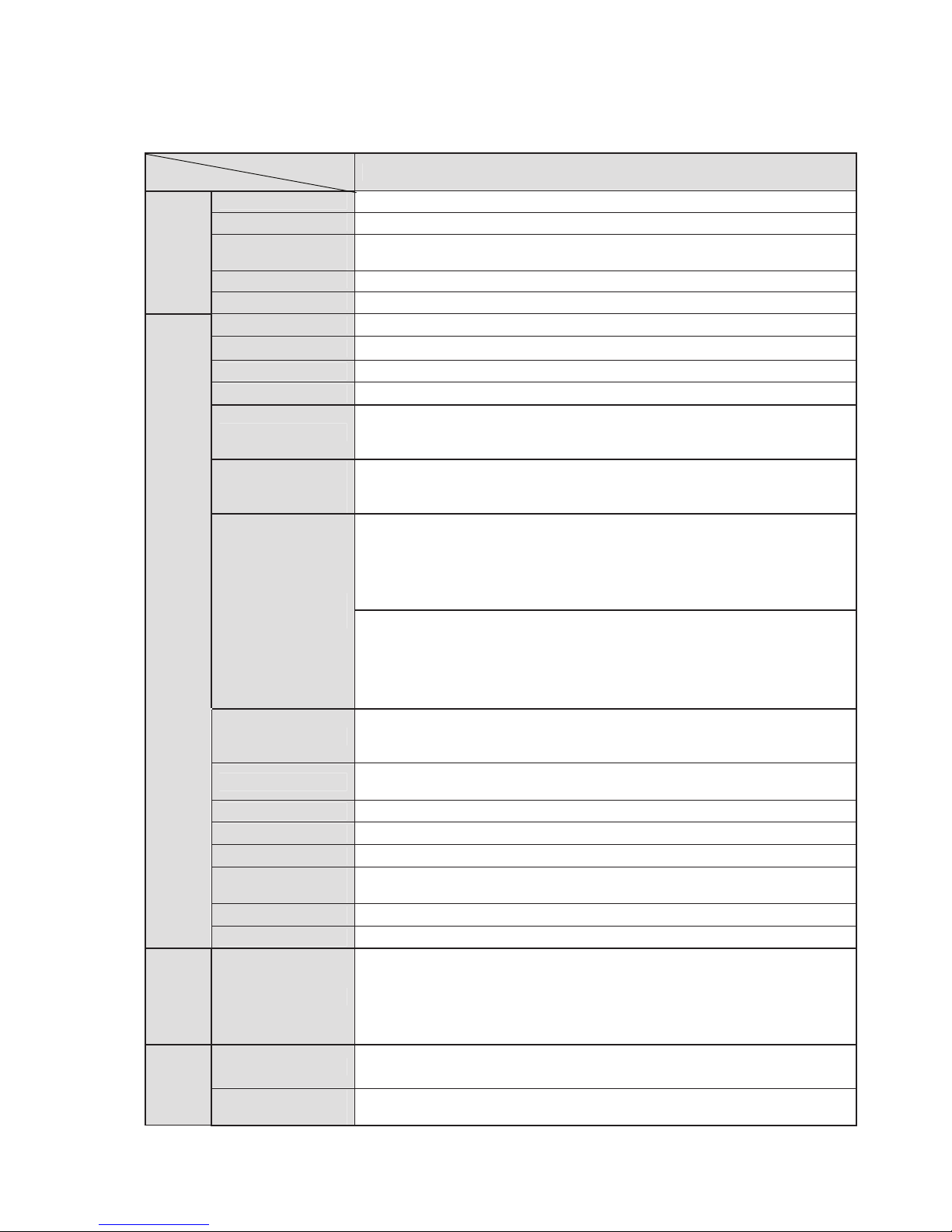
6SHFLILFDWLRQV
Please refer to the following sheet for IPC performance specification.
Model
Parameter
System
Video Parameter
Video
and
Backup
Main Processor TI Davinci high performance DSP
OS Embedded LINUX
System
Resources
User Interface Remote operation interface such as WEB, DSS, PSS
System Status Bit stream statistics, log, and software version.
Image Sensor 1/3-inch CMOS
Pixel 1280(H)*960(V)
Gain Control Fixed/Auto
White Balance Manual/Auto
Exposure Mode
Video
Compression
Standard
Video Frame
Rate
Video Bit Rate
Video Flip
Snapshot Max 1f/s snapshot. File extension name is JPEG.
Privacy Mask Supports max 4 privacy mask zones
Video Setup Support parameter setup such as bright, contrast.
Video
Information
Lens 2.8mm, 3.6mm, 6mm, 8mm. Fixed focus.
Lens Interface M12. Lens is the default accessories
Motion Detect
Record
Record Priority Manual>External alarm >Video detect>Schedule
IPC-HDW2100P/N Series
Support real-time network, local record, and remote operation at the
same time.
Manual/Auto
PAL: It ranges from 1/3 to 1/10000
NTSC: It ranges from 1/4 to 1/10000
H.264/JPEG/MJPG
PAL:
Main stream(1280*960@15fps),
extra stream,˄352*288@15fps)˅
Main stream˄1280*720@25fps˅ˈ
extra stream˄352*288@25fps˅
NTSC:
Main stream˄1280*960@15fps˅ˈ
extra stream˄352*240@15fps˅
Main stream˄1280*720@30fps˅ˈ
extra stream˄352*240@30fps˅
H.264: 56Kbps-8192Kbps.
MJPEG is adjustable and bit rate is adjustable.
Support customized setup.
Support mirror.
Support flip function.
Channel title, time title, motion detect, camera masking.
396 (18*22) detection zones˗sensitivity level ranges from 1 to 6 (The
6th level has the highest sensitivity)
Activation event: video storage, image snapshot, log, email function
and etc.
Storage
Management
Support display local storage status
2
Page 47

Network
ʽ
)DFWRU\'HIDXOW6HWXS
Wire Network
Network Protocol
Remote
Operation
Restore Default
Setup
IR light 12 LED. IR light 20M.
General Parameter
Power DC12V power and PoE.
Power
Consumption
Working
Temperature
Working
Humidify
Dimensions(mm)
Weight
Installation Fixed on the wall, ceiling and etc.
1- channel wire Ethernet port, 10/100 Base-T Ethernet
Standard HTTP, TCP/IP, ARP, IGMP, ICMP, RTSP, RTP,UDP, RTCP,
SMTP, FTP, DHCP, DNS, DDNS, PPPOE, UPNP, NTP, Bonjour,
SNMP.
Monitor, system setup, file download, log information, maintenance ,
upgrade and etc
Built-in Reset button
Warning
Do not connect these two power supplying sources to the device
at the same time; it may result in device damage!
4W MAX
-10ć~+60ć
10%~90%
113h86
280g˄Excluding box˅
Please refer to the following sheet for factory default setup information.
Setup Item
Conditions
Camera
Brightness 50
Contrast 50
Hue 50
Saturation 50
Gain Mode Auto
Gain Limit 50
Exposure Mode Auto
Scene Mode Auto
Day/night Mode Auto
BLC Off
Flip Off
Video
Video bit stream
Main
Stream
Bit stream
type
Encode mode H.264
Resolution 720P˄1280*720˅
Frame Rate
˄FPS˅
Bit Rate Type CBR
Default Setup
IPC-HDW2100P/N Series
General
PAL: 25
NTSC:30
3
Page 48

Setup Item
Default Setup
IPC-HDW2100P/N Series
Recommende
d Bit
2048-6144Kb/S
Bit Rate 4096
I Frame
interval
50
Watermark Enable
Snapshot
Video Overlay
Path
Network
TCP/IP
Sub
Stream
Watermark
character
DigitalCCTV
Enable Enable
Bit stream
type
Encode
mode
General
H.264B
Resolution CIF(352*288/352*240)
Frame Rate
˄FPS˅
PAL: 25
NTSC:30
Bit Rate Type CBR
Recommend
ed Bit
192-1024Kb/S
Bit Rate 1024
I Frame
interval
Snapshot
Type
50
General
Image Size 720P˄1280*720˅
Quality 5
Interval 1s
Privacy Mask Disable
Channel Title Enable
Time Title Enable
Snapshot
Path
Record Path C:\RecordDownload
C:\PictureDownload
Host Name IPC
Ethernet Card Wire(Default)
Mode Static
Mac Address
Device MAC address when it is shipped out of the
factory
IP Version IPV4
IP Address 192.168.1.108
Subnet Mask 255.255.255.0
4
Page 49

Setup Item
Default
Gateway
Default Setup
IPC-HDW2100P/N Series
192.168.1.1
Connection
PPPoE
Preferred
DNS
Alternate
DNS
8.8.8.8
8.8.8.8
Enable
ARP/Ping set
device IP
Enable
address
service
Max
Connection
10
TCP Port 37777
UDP Port 37778
HTTP Port 80
RTSP Port 554
Enable Disable
Username none
Password N/A
Server Type DisableˈCN99 DDNS
Server IP none
Server Port 80
DDNS
Domain
Name
none
User none
Password ****
Update
Period
5 minutes
IP Filter Trusted sites Disable
SMTP(Email)
SMTP Server none
Port 25
Anonymity Disable
User Name anonymity
Password ****
Sender none
Authenticatio
n (Encryption
N/A
mode)
Title (Subject) IPC Message
5
Page 50

Setup Item
UPnP Enable UPnP Disable
Default Setup
IPC-HDW2100P/N Series
Attachment N/A
Mail Receiver 0 seconds
Email Test Disableˈinterval=60 minutes
SNMP v1 Disable
SNMP v2 Disable
SNMP Port 161
Event
SNMP
Bonjour
Multicast
QoS
Video detect
Motion Detect
Video
Masking
Abnormality
Disconnection
IP Conflict
Read
Community
Write
Community
public
private
Trap Address N/A
Trap Port 162
Enable Enable
Server Name Device factory SN
Multicast
Address
239.255.42.42
Port 36666
Real-time
Monitor
0
Command 0
Enable Disable
Anti-dither 5 seconds
Sensitivity 3
Record
Channel
Enable
Record Delay 10 seconds
Send Email Disable
Snapshot Disable
Enable Disable
Record
Channel
Enable
Record Delay 10 seconds
Send Email Disable
Snapshot Disable
Enable Disable
Record Enable
Record Delay 10 seconds
Enable Disable
Record Enable
6
Page 51

Setup Item
Default Setup
IPC-HDW2100P/N Series
Record Delay 10 seconds
Storage
System
Storage
FTP
Record Control
General
Local Host
Enable FTP Disable
Server IP N/A
Port 21
Username anonymity
Password N/A
Remote path share
Emergency
(Local)
Disable
Pack Duration 8 minutes
Pre-record 5 seconds
Disk Full Overwrite
Record Mode Auto
Bit Stream Main Stream
Device No Device MAC address
Language English
Video
Standard
NTSC
Date Format Y-M-D
Time Format 24H
Date and time
Auto Maintenance
Time Zone GMT+08:00
System Time Sync
DST Disable
DST Type Week
Start Time 00:00:00 of the first Sunday of the month
End Time 00:00:00 of the second Monday of the month
NTP Disable
NTP Server clock.isc.org
Port 37
Update
Period
10 minutes
Auto Reboot Enable
Auto Delete
Old Files
Disable
7
Page 52
6WUXFWXUH
&RPSRQHQWV
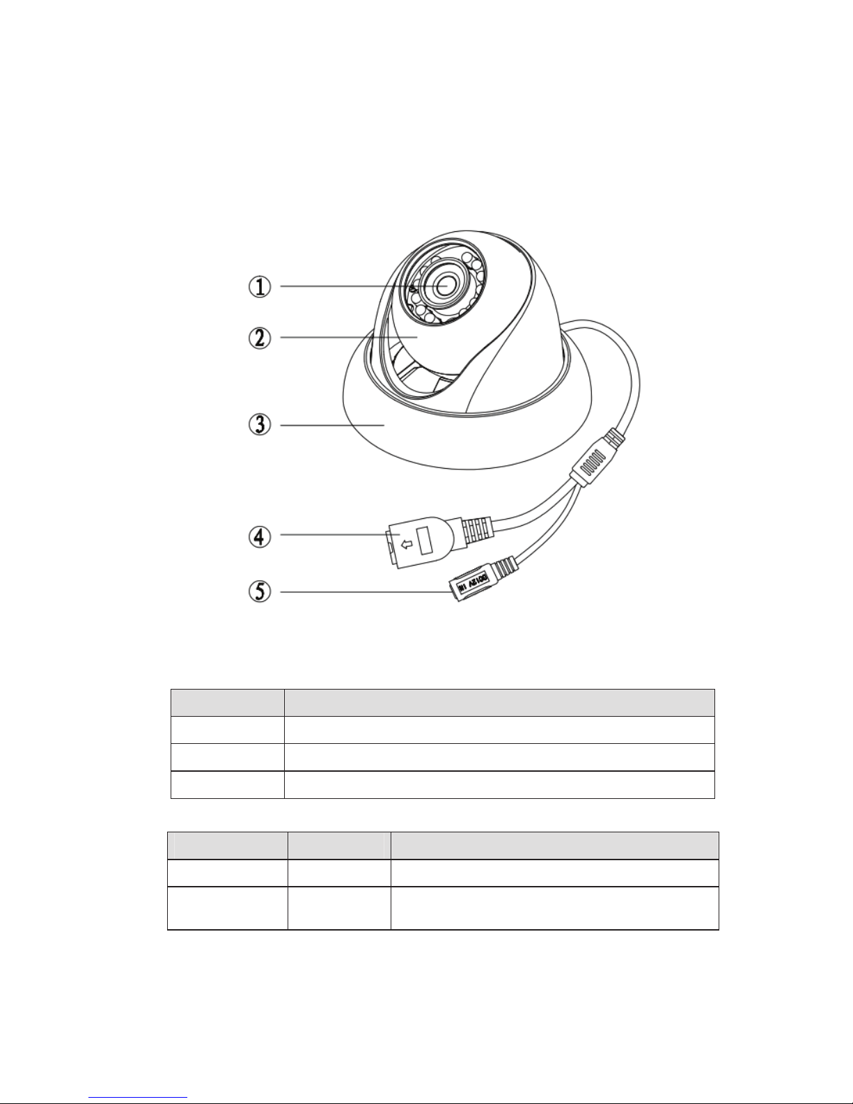
)UDPHZRUNDQG'LPHQVLRQ
You can refer to the following figure for multiple-function combination cable information. See Figure
2-1
.
Please refer to the following sheet for detailed information.
Component Component Name
Component 1 Device lens
Component 2 Dome body
Component 3 Dome enclosure
Port Name Function Note
Port 4 Network port Connect to standard Ethernet cable.
Port 5
DC 12V
power
Power input port. Input DC 12V.
Figure 2-1
8
Page 53
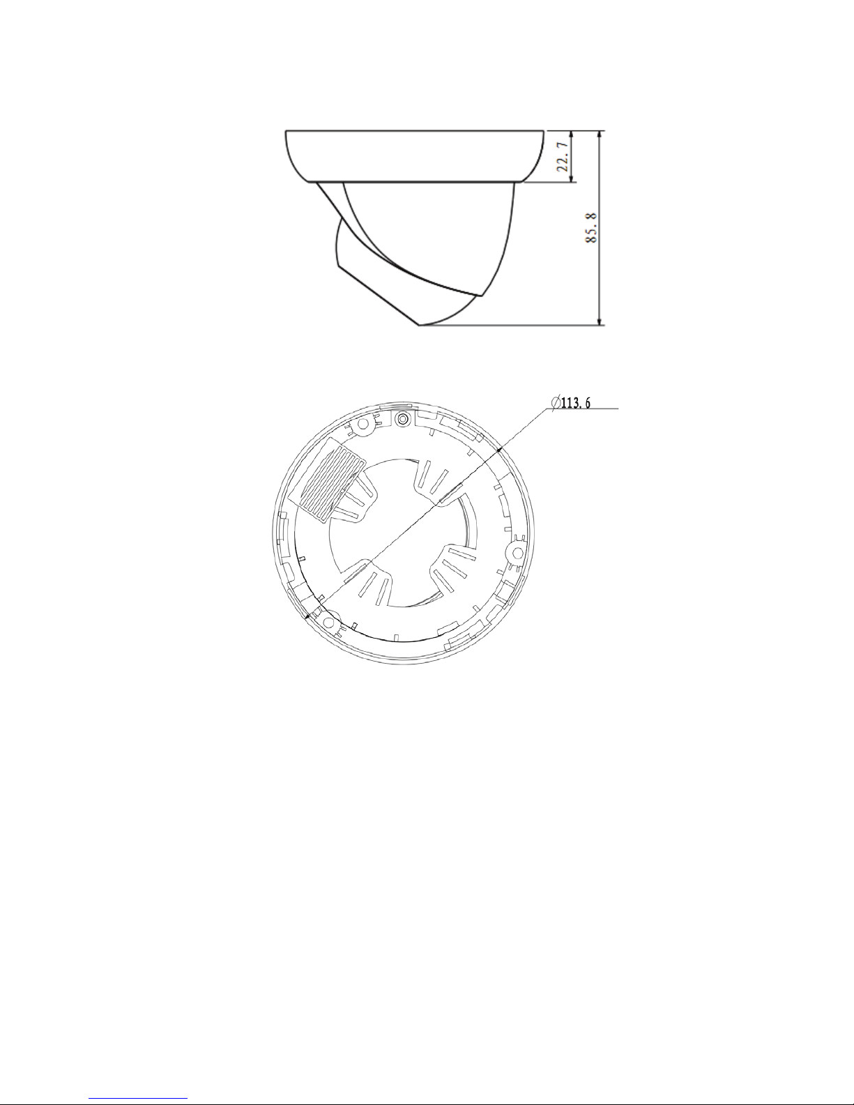
Please refer to the following two figures for dimension information. The unit is mm. See Figure 2-2 and
Figure 2-3.
Figure 2-2
Figure 2-3
9
Page 54

'HYLFH,QVWDOODWLRQ
,QVWDOODWLRQ6WHSV
Important
Before the installation, please make sure the installation environments can at least support 3x weight
of the camera.
Please follow the steps listed below to install the device. Please refer to Figure 3-1 for reference.
Step 1
Turn clockwise to remove the decoration ring from the snap joints.
Step 2
Please take the installation position map in the accessories bag, and then paste it on the ceiling or the
wall according to your monitor area requirements. Draw and then dig three plastic expansion bolts
holes in the installation surface and then insert three expansion bolts in the holes. Secure these three
bolts firmly. Please draw the cable out from the cable exit when you install the device.
Step 3
Adjust the device installation pedestal to the proper position and then line up the three screw holes in
the device pedestal to the three plastic expansion bolt holes in the installation position. Put the three
self-tapping screws in the three plastic expansion bolts firmly. Loosen the M3X8 cross recessed pan
head slot screw of the pedestal to unfasten the preforming. (Do not remove, loosen a little bit will be
OK.). Adjust the lens to the proper monitor angle and then use the original preforming to turn the M3X8
cross recessed pan head slot screw back.
Step4
Line up the three spigots of the decoration ring to the jags from the bottom to the top and then turn
clockwise until you hear a clear sound ”KA”. Now the installation is complete.
Important
Please pay attention to the dome camera direction when you are installing. Please refer to the
following figure for detailed information. See Figure 3-2.
Figure 3-1
10
Page 55
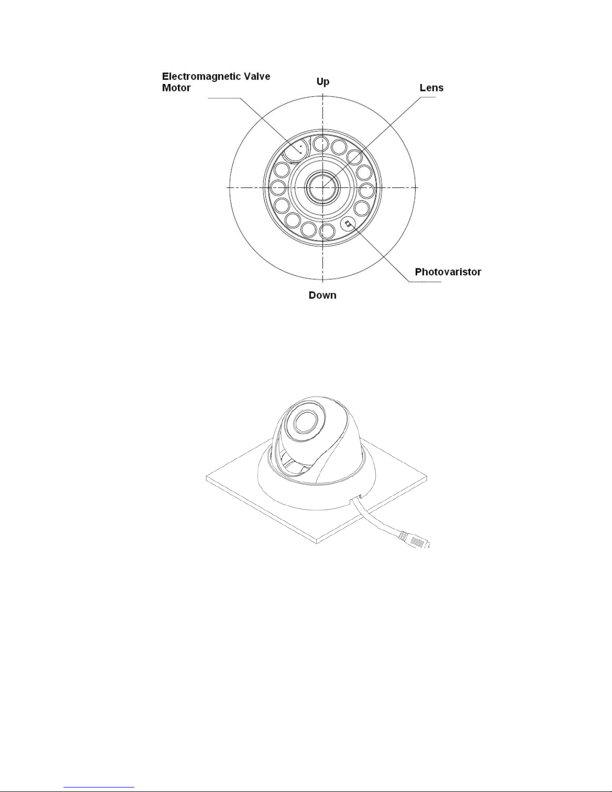
Figure 3-2
Note
This series product supports two cable exits. One is from the bottom and the other is from the side.
Please refer to the following figure for cable exit from the side information.
Figure 3-3
Please earth the GND port of the device to enhance the device reliability. The GND port is near the
cable exit port on the rear of the dome. The GND screw uses the M2X5 pan screw.
11
Page 56
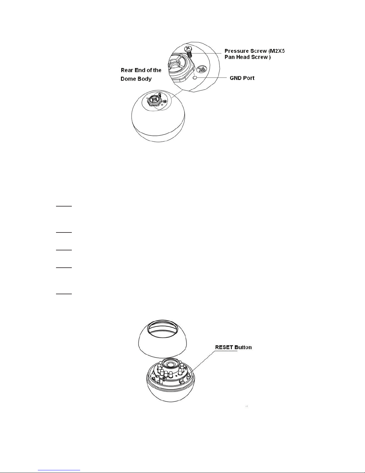
Figure 3-4
5HVWRUH)DFWRU\'HIDXOW6HWXS,QWURGXFWLRQ
Important
Please use RESET button when device is running.
Step1
Please refer to step1 and step2 in chapter 3.1to loose the dome body. Push a little bit; you can take
the dome body from the gland cover.
Step2
Take the dome body out and then turn the top cover hard to remove.
Step3
Slightly press the RESET button to complete the reset function. See Figure 3-5.
Step4
Turn the top cover back to the original position. Please make sure it reaches the original position,
otherwise it may result in water leakage!
Step5
Put the dome back to the gland cover. Please refer to step4 in chapter 3.1 to install the decoration ring
back.
Figure 3-5
12
Page 57
4XLFN&RQILJXUDWLRQ7RRO
2YHUYLHZ
2SHUDWLRQ
Quick configuration tool can search current IP address, modify IP address. At the same time, you can
use it to upgrade the device.
Please note the tool only applies to the IP addresses in the same segment.
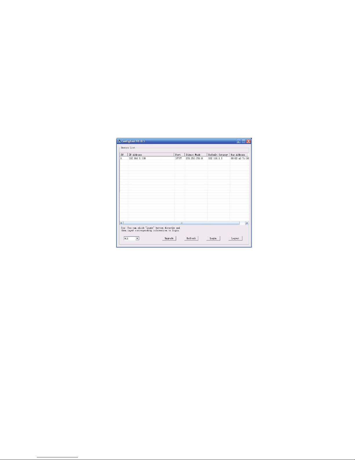
Double click the ĀConfigTools.exeāicon, you can see an interface is shown as in Figure 4-1.
In the device list interface, you can view device IP address, port number, subnet mask, default
gateway, MAC address and etc.
Figure 4-1
Select one IP address and then right click mouse, you can see an interface is shown as in Figure 4-2.
Note:
You can set the IP address, subnet mask and gateway for the IPC and PC. Please note IPC IP
address and PC IP address shall be in the same network segment if there is no router. IPC default IP
address is 192.168.1.108. If there is a router, please set the corresponding gateway and subnet mask.
The factory default user name is admin and password is admin. For security reasons, please modify
your password after you first login.
For detailed WEB operation, please refer to the IPC Web Operation Manual in the resource CD.
13
Page 58
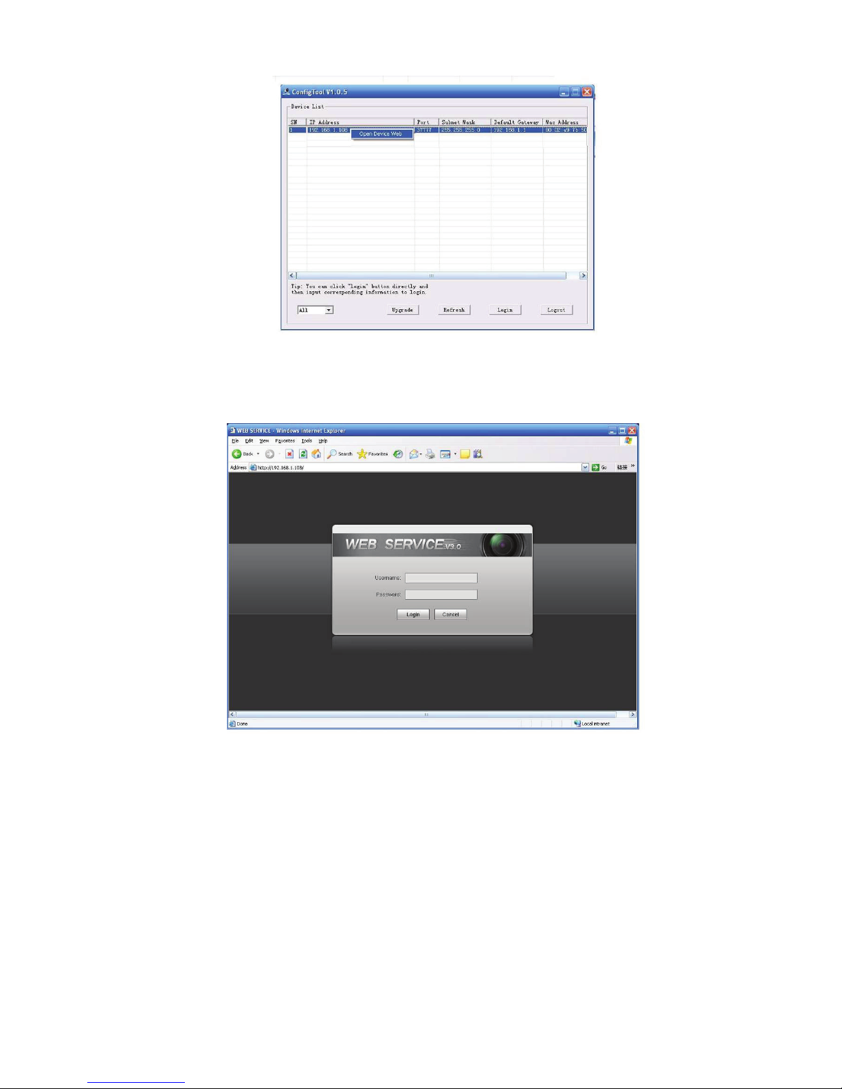
Figure 4-2
Select the “Open Device Web” item; you can go to the corresponding web login interface. See Figure
4-3.
If you want to modify the device IP address without logging in the device web interface, you can go to
the configuration tool main interface to set.
In the configuration tool search interface (Figure 4-1), please select a device IP address and then
double click it to open the login interface. Or you can select an IP address and then click the Login
button to go to the login interface. See Figure 4-4.
In Figure 4-4, you can view device IP address, user name, password and port. Please modify the
corresponding information to login.
Please note the port information here shall be identical with the port value you set in TCP port in Web
Network interface. Otherwise, you can not login the device.
If you are use device background upgrade port 3800 to login, other setups are all invalid.
Figure 4-3
14
Page 59
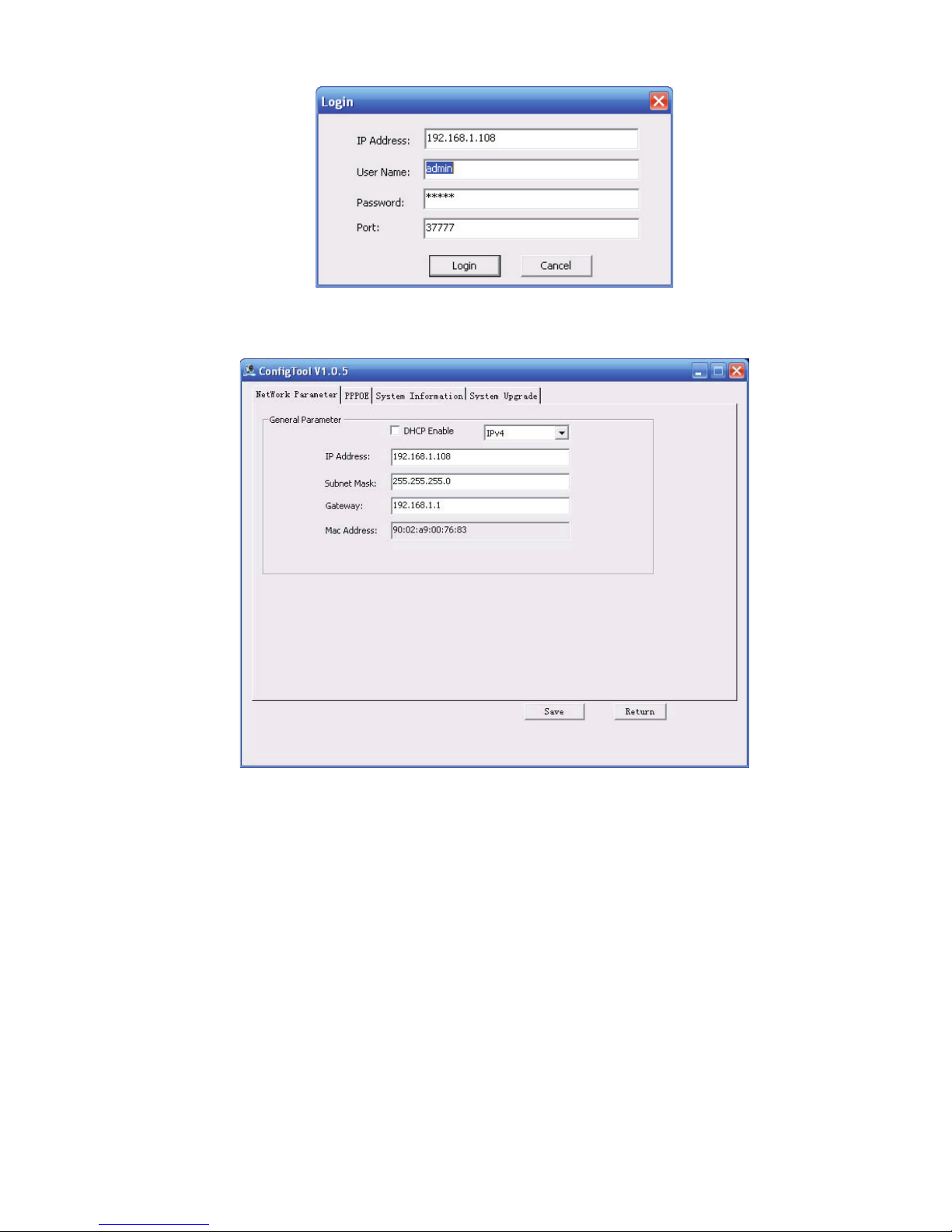
Figure 4-4
After you logged in, the configuration tool main interface is shown as below. See Figure 4-5.
For detailed information and operation instruction of the quick configuration tool, please refer
to the Quick Configuration Tool User’s Manual included in the resources CD.
Figure 4-5
15
Page 60
:HE2SHUDWLRQ
1HWZRUN&RQQHFWLRQ
/RJLQDQG/RJRXW
This series IPC product support the Web access and management via PC.
Web includes several modules includes monitor channel preview, system configuration, alarm and etc.
Please follow the steps listed below for network connection.
z Make sure the IPC has connected to the network properly.
z Please set the IP address, subnet mask and gateway of the PC and the IPC respectively. IPC
default IP address is 192.168.1.108. Subnet mask is 255.255.255.0. Gateway is 192.168.1.1
z Use order ping ***.***.***.***(* IP camera address) to check connection is OK or not.
Open IE and input IP camera address in the address bar.
For example, if your camera IP is 192.168.1.108, then please input http:// 192.168.1.108 in IE address
bar. See Figure 5-1.
Input your IP
address here
The login interface is shown as below. See Figure 5-2.
Please input your user name and password.
Default factory name is admin and password is admin.
Note: For security reasons, please modify your password after you first login.
Figure 5-1
16
Page 61
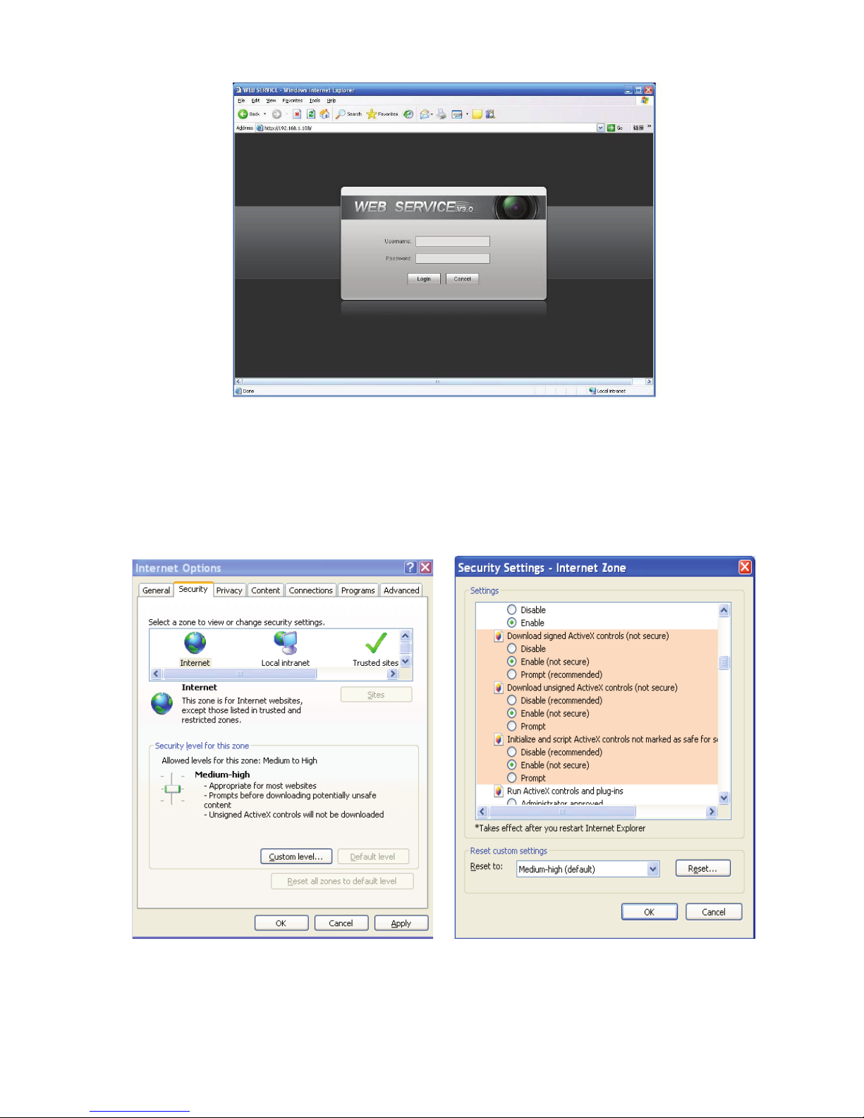
Figure 5-2
If it is your first time to login in, system pops up warning information to ask you whether install control
webrec.cab
automatically install the control. When system is upgrading, it can overwrite the previous Web too.
If you can’t download the ActiveX file, please check whether you have installed the plug-in to disable
the control download. Or you can lower the IE security level. See Figure 5-3.
or not after you logged in for one minute. Please click OK button, system can
After you logged in, you can see the main window. See Figure 5-4.
Figure 5-3
17
Page 62
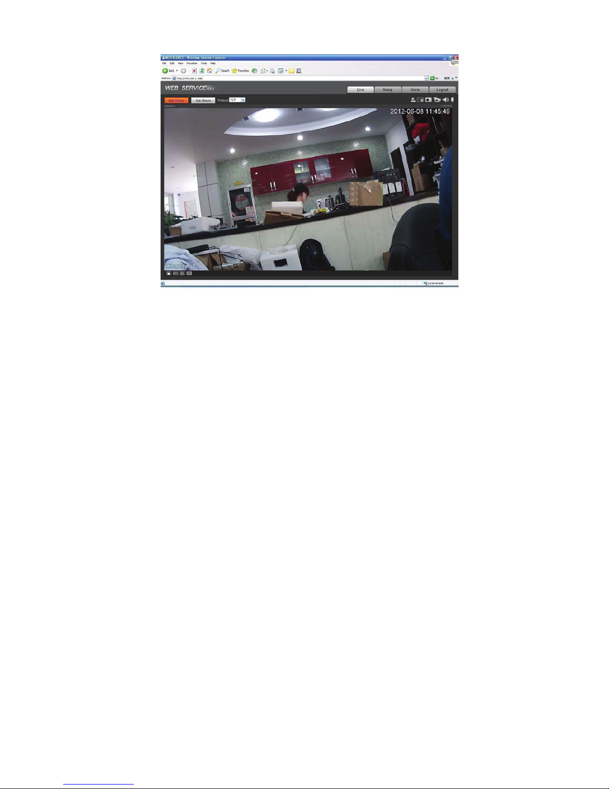
Figure 5-4
Please refer to the Web Operation Manual included in the resource CD for detailed operation
instruction.
18
Page 63

)$4
Bug
I can not boot up
the device or
operate properly.
The water leakage
occurred.
IR video is poor. Do not use the proper supplying power. The IR light can not turn on
I can not upgrade
the device via
network.
I can not login the
client-end or the
WEB.
Please click RESET button for at least five seconds to restore
factory default setup.
The unauthorized front or rear cap remove many result in water
leakage.
The glass front cap has sustained heavy push or strike.
The waterproof plug of the rear cap becomes loosen.
completely.
The object is out of the IR distance range of current device.
IR-CUT does not turn to the night mode. The photosensitive chip of
the front-end can not sense the IR light.
When network upgrade operation failed, you can use port 3800 to
continue upgrade.
For Windows OS 98 or Windows ME user, if you can not install the
client-end or can not view after the installation. We recommend the
win2000sp4 OS or install the client-end of the low version.
The Active X control is blocked.
The display card version shall be dx8.1 or higher.
Network connection error occurred.
Invalid network setup.
Invalid user name or password.
I can not play the
download file.
To guarantee
setup update
Power adapter
There is no player.
There is no DX8.1 or higher.
For the MEDIA PLAYER, there shall be Div X503Bundle.exe plugin
if you play the .AVI file.
For Windows XP user, you need to install the plugin
DivX503Bundle.exe and ffdsho-2004 1012.exe.
After you modified the important setup, please reboot the device via
the software to make sure the setup has been updated to the
storage medium.
The general power adapter can work ranging from 0ć to 40 ć. The
device may result in unstable power supply when the temperature
exceeds the working temperature.
Please replace an industry-level power adapter if you are using in
the harsh environments.
19
Page 64

$SSHQGL[7R[LFRU+D]DUGRXV0DWHULDOVRU(OHPHQWV
Component
Name
Circuit Board
Component
Device
Construction
Material
Wire and Cable
Packing
Components
Accessories ż ż ż ż ż ż
O: Indicates that the concentration of the hazardous substance in all homogeneous materials in the
parts is below the relevant threshold of the SJ/T11363-2006 standard.
X: Indicates that the concentration of the hazardous substance of at least one of all homogeneous
materials in the parts is above the relevant threshold of the SJ/T11363-2006 standard. During the
environmental-friendly use period (EFUP) period, the toxic or hazardous substance or elements
contained in products will not leak or mutate so that the use of these (substances or elements) will not
result in any severe environmental pollution, any bodily injury or damage to any assets. The consumer
is not authorized to process such kind of substances or elements, please return to the corresponding
local authorities to process according to your local government statutes.
Pb Hg Cd Cr VI PBB PBDE
ż ż ż ż ż ż
ż
ż
ż ż ż ż ż ż
Toxic or Hazardous Materials or Elements
ż ż ż ż ż
ż ż ż ż ż
Note
z This user’s manual is for reference only. Slight difference may be found in user interface.
z All the designs and software here are subject to change without prior written notice.
z All trademarks and registered trademarks mentioned are the properties of their respective
owners.
z If there is any uncertainty or controversy, please refer to the final explanation of us.
z Please visit our website for more information.
20
Page 65

IPC Web3.0 Operation Manual
Version 3.0.2
Page 66

Table of Contents
1HWZRUN&RQQHFWLRQ ...................................................................................................................1
0DLQ,QWHUIDFH,QWURGXFWLRQ........................................................................................................2
/RJLQ .............................................................................................................................. 2
/LYH,QWHUIDFH .................................................................................................................4
(QFRGH6HWXS ................................................................................................................4
6\VWHP0HQX.................................................................................................................5
9LGHR:LQGRZ)XQFWLRQ2SWLRQ .................................................................................. 5
9LGHR:LQGRZ6HWXS ....................................................................................................6
37=&RQWURO.................................................................................................................................. 8
6HWXS...........................................................................................................................................11
&DPHUD ......................................................................................................................... 11
4.1.1 Conditions .............................................................................................................11
4.1.2 Video ......................................................................................................................14
4.1.3 Audio ......................................................................................................................19
1HWZRUN.........................................................................................................................20
4.2.1 TCP/IP ...................................................................................................................20
4.2.2 Connection ............................................................................................................22
4.2.3 PPPoE ...................................................................................................................23
4.2.4 DDNS .....................................................................................................................23
4.2.5 IP filter....................................................................................................................24
4.2.6 SMTP ˄e-mail˅ .................................................................................................25
4.2.7 UPnP......................................................................................................................27
4.2.8 SNMP.....................................................................................................................28
4.2.9 Bonjour ..................................................................................................................30
4.2.10 Multicast .........................................................................................................30
i
Page 67

4.2.11 WIFI................................................................................................................. 31
4.2.12 Qos..................................................................................................................33
(YHQW ............................................................................................................................. 34
4.3.1 Video detect ..........................................................................................................34
4.3.2 Alarm......................................................................................................................39
4.3.3 Abnormity ..............................................................................................................42
6WRUDJH .........................................................................................................................44
4.4.1 Record schedule and snapshot schedule ........................................................ 44
4.4.2 Destination ............................................................................................................44
4.4.3 Record control ......................................................................................................47
6\VWHP..........................................................................................................................48
4.5.1 General ..................................................................................................................48
4.5.2 Account..................................................................................................................50
4.5.3 PTZ.........................................................................................................................54
4.5.4 Default.................................................................................................................... 54
4.5.5 Import/Export ........................................................................................................55
4.5.6 Auto maintenance ................................................................................................ 55
4.5.7 Firmware update ..................................................................................................56
,QIRUPDWLRQ ...................................................................................................................56
4.6.1 Version...................................................................................................................56
4.6.2 Log..........................................................................................................................57
$ODUP...........................................................................................................................................59
/RJRXW........................................................................................................................................60
Important
The following functions are for reference only. Some series products may not
support all the functions listed below.
ii
Page 68

1HWZRUN&RQQHFWLRQ
This series IPC product support the Web access and management via PC.
Web includes several modules includes monitor channel preview, PTZ control, system configuration,
alarm and etc.
Please follow the steps listed below for network connection.
z Make sure the IPC has connected to the network properly.
z IPC IP address and PC IP address shall be in the same network segment. If there is router, please
set the corresponding gateway and subnet mask.
z Use order ping ***.***.***.***(* IP camera address) to check connection is OK or not.
1
Page 69
0DLQ,QWHUIDFH,QWURGXFWLRQ
/RJLQ
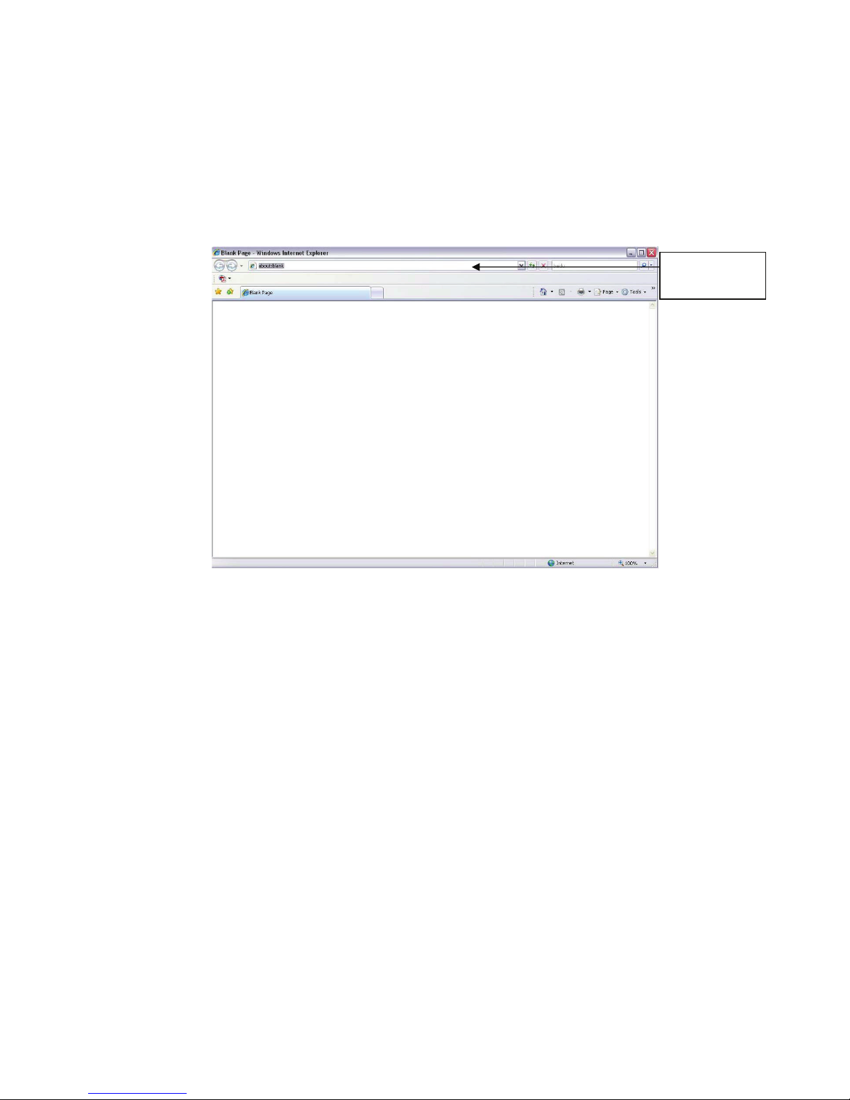
Open IE and input IP camera address in the address bar.
For example, if your camera IP is 192.168.1.108, then please input http:// 192.168.1.108 in IE address
bar. See Figure 2-1.
Input your IP
address here
Figure 2-1 IE
The login interface is shown as below. See Figure 2-2.
Please input your user name and password.
Default factory name is admin and password is admin.
Note: For security reasons, please modify your password after you first login.
2
Page 70
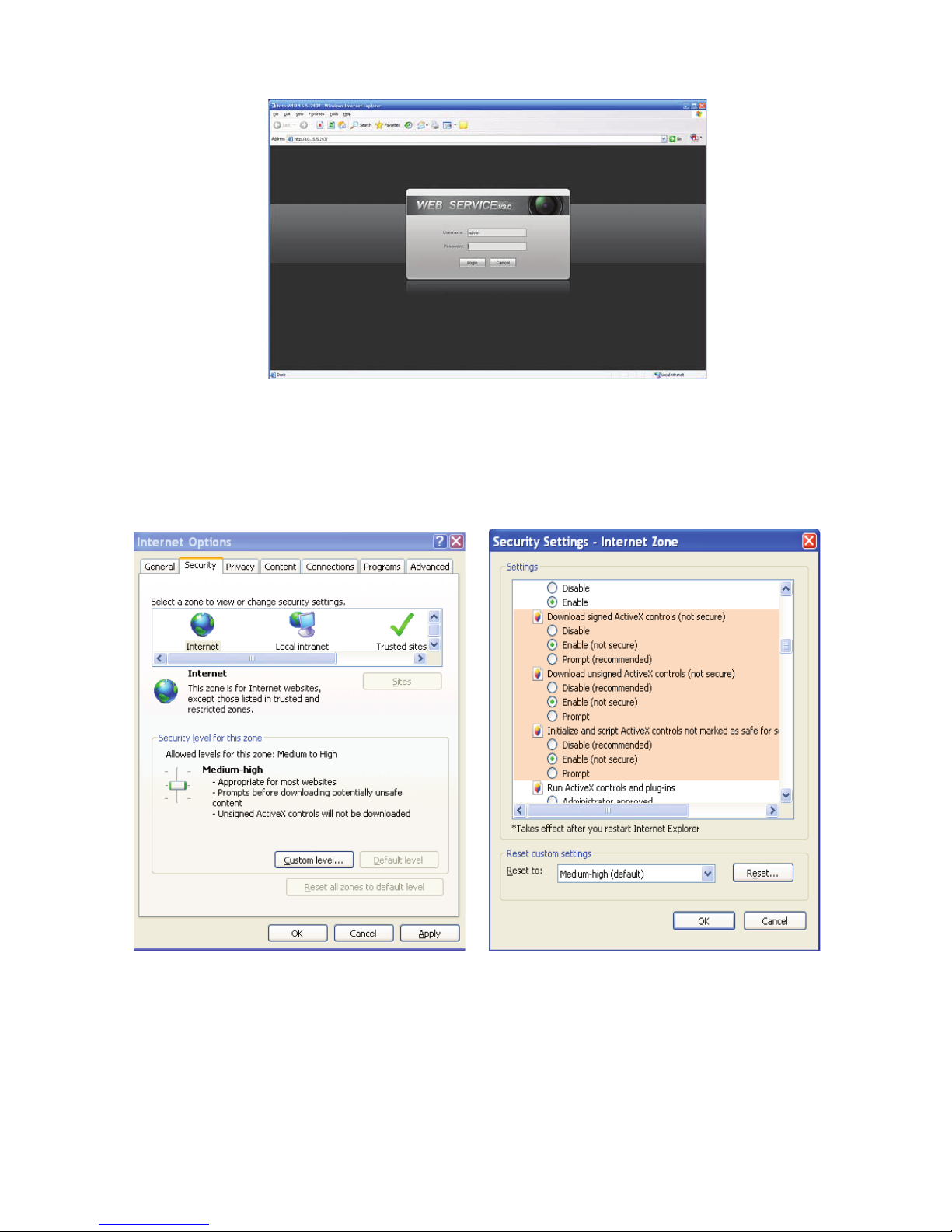
Figure 2-2 Login Interface
If it is your first time to login in, system pops up warning information to ask you whether install control
webrec.cab
upgrading, it can overwrite the previous Web too.
If you can’t download the ActiveX file, please check whether you have installed the plug-in to disable the
control download. Or you can lower the IE security level. See Figure 2-3.
or not. Please click OK button, system can automatically install the control. When system is
Figure 2-3 Security Settings
3
Page 71
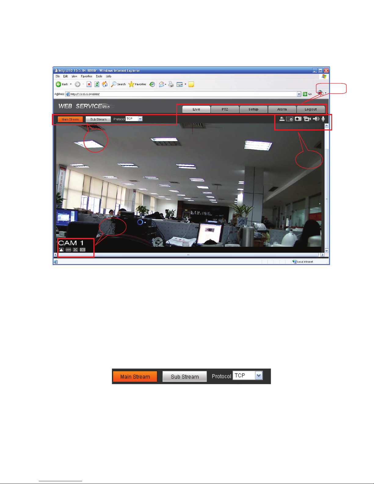
/LYH,QWHUIDFH
(QFRGH6HWXS
ķ
ĺ
ĸ
Ĺ
After you logged in, you can see the live monitor window. See Figure 2-4.
Figure 2-4 Live Interface
There are four sections:
z Section 1: Encode setup bar
z Section 2: System menu
z Section 3: Window function option bar
z Section 4: Window adjust bar
The encode setup interface is shown as in Figure 2-5.
4
Page 72
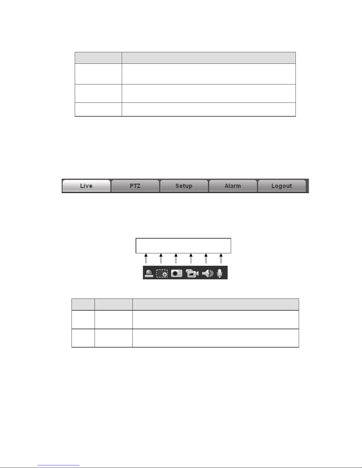
Figure 2-5 Encode setup
6\VWHP0HQX
9LGHR:LQGRZ)XQFWLRQ2SWLRQ
Please refer to the following sheet for detailed information.
Parameter Function
Main stream
Sub (Extra)
stream
Protocol
In normal network width environment, main stream can record
audio/video file and realize network monitor.
You can set the main stream resolution if your device supports.
If network width is not sufficient, you can use sub stream to
realize network monitor.
You can select stream media protocol from the dropdown list.
There are three options: TCP/UDP/Multicast
System menu is shown as in Figure 2-6.
Please refer to chapter 2.2 Live, chapter 3 PTZ, chapter 4 Setup, chapter 5 Alarm, chapter 6 Log out
for detailed information.
Figure 2-6 System Menu
The interface is shown as below. See
Figure 2-7.
1 2 3 4 5 6
Figure 2-7 Video Window Function
Please refer to the following sheet for detailed information.
SN Parameter Function
1 Alarm
output
2 Digital
zoom
Click it to generate an alarm output.
Click this button and then left drag the mouse in the zone to
zoom in. Right click mouse system restores original status.
5
Page 73
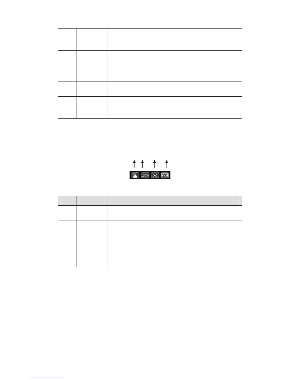
3 Snapshot
9LGHR:LQGRZ6HWXS
4 Record
5 Audio
output
You can snapshoot important video. All images are
memorized in system folder: \ picture download (default).
You can go to Setup->Camera->Video->Path to modify the
local record save path.
When you click local record button, the system begins
recording. The recorded file is saved to system folder: \
RecordDownload(default).
You can go to Setup->Camera->Video->Path to modify the
local record save path.
Turn on or off audio when you are monitoring.
Some series product does not support this function.
6 Bidirectional
talk
Click it to begin audio talk. You can go to Setup->Camera>Audio to set bidirectional talk mode.
Some series product does not support this function.
The interface is shown as in Figure 2-8.
1 2 3 4
Figure 2-8 Video Window Setup
Please refer to the following sheet for detailed information.
SN Parameter Function
1 Image
control
2 Original
size
3 Full screen Click it to go to full-screen mode. Double click the mouse or
Click it to open picture setup interface. See Figure 2-9. This
interface is on the top right pane.
Click this button to go to original size. It is to display the actual
size of the video stream. It depends on the resolution of the
bit stream.
click the Esc button to exit the full screen.
4 Width and
height ratio
The picture setup interface is shown as in Figure 2-9.
Click it to restore original ratio or suitable window.
6
Page 74
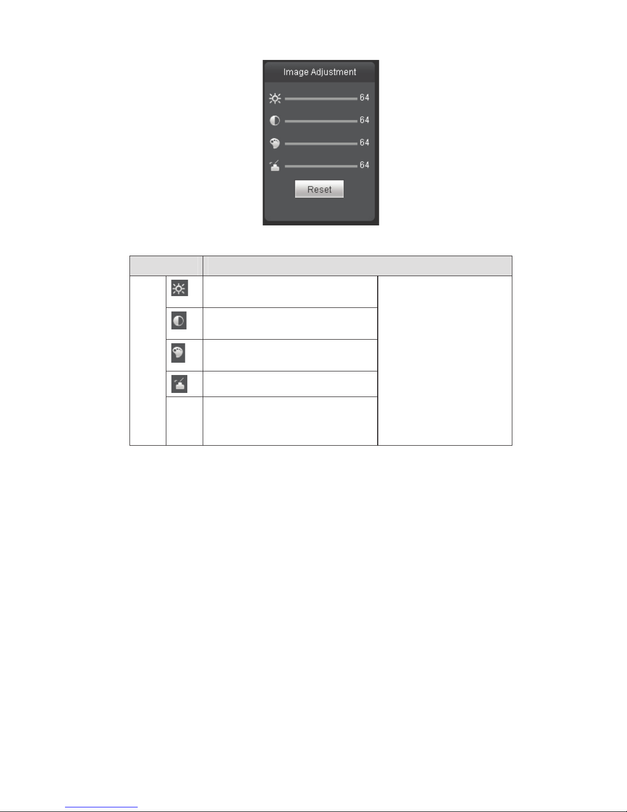
Figure 2-9
Please refer to the following sheet for detailed information.
Parameter Function
Video
setup
It is to adjust monitor video
brightness.
It is to adjust monitor video contrast
ness.
It is to adjust monitor video
saturation.
It is to adjust monitor video hue.
Reset Restore brightness, contrastness
saturation and hue to system default
setup.
Note:
z All the operations here
apply to WEB end
only.
z Please go to Setup-
>Camera->Conditions
to adjust
corresponding items.
7
Page 75
37=&RQWURO
Please note some series product does not support this function.
Before PTZ operation, please make sure you have properly set PTZ protocol. (Please go to Setup-
>System->PTZ to set.).
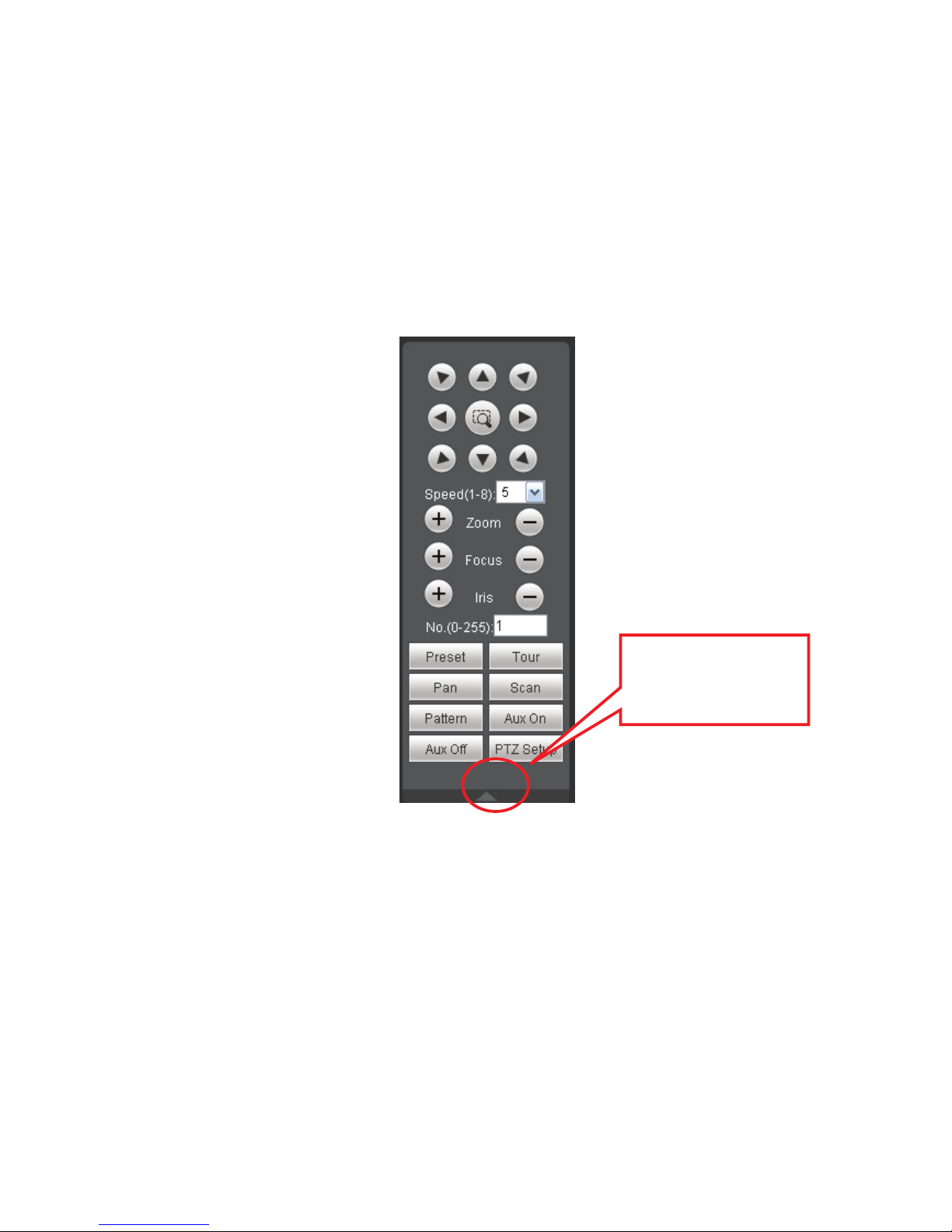
Here you can view direction keys, speed, zoom, focus, iris, preset, tour, pan, scan, pattern, aux close,
and PTZ setup button. See Figure 3-1.
z PTZ direction: PTZ supports eight directions: left/right/up/down/upper left/upper right/bottom
left/bottom right.
z Speed: The step 8 speed is faster than step 1.
Figure 3-1 PTZ Interface
Click PTZ set button, the interface is shown as in Figure 3-2.
You can click this icon to
display or hide the PTZ
control platform.
8
Page 76
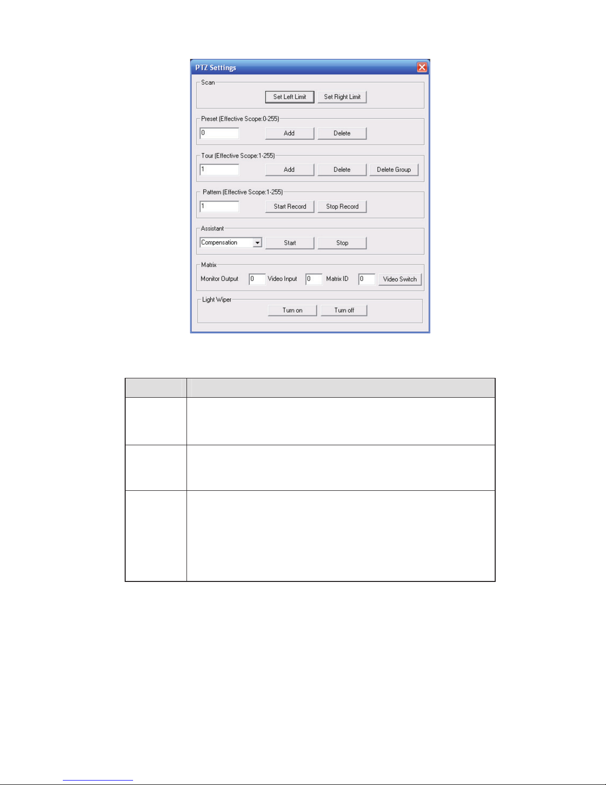
Figure 3-2 PTZ Setup
Please refer to the following sheet for PTZ setup information.
Parameter Function
Scan
Preset
Tour
z Move the camera to you desired location and then click left limit
button.
z Then move the camera again and then click right limit button to
set a right limit.
Use direction keys to move the camera to your desired location and
then input preset value. Click add button, you have set one preset.
The preset value ranges from 1 to 80. (It may vary due to different
protocols.)
z Input auto tour value and preset value. Click add button, you
have added one preset in the tour.
z Repeat the above procedures you can add more presets in one
tour.
z Or you can click delete button to remove one preset from the
tour.
The tour value ranges from 1 to 255. (It may vary due to different
protocols.)
9
Page 77

Parameter Function
Pattern
You can input pattern value and then click start record button to
begin PTZ movement. Please go back to Figure 3-1 to implement
camera operation. Then you can click stop record button in Figure
3-2. Now you have set one pattern.
Assistant
Matrix
Light and
wiper
The assistant items include: BLC, Digital zoom, night vision, camera
brightness, flip.
You can select one option and then click start or stop button.
Please select the matrix X, and then input the corresponding monitor
output number, video input channel number, and then you can click
video switch button to complete the operation.
You can enable or disable the light/wiper.
10
Page 78
6HWXS
&DPHUD
4.1.1 Conditions
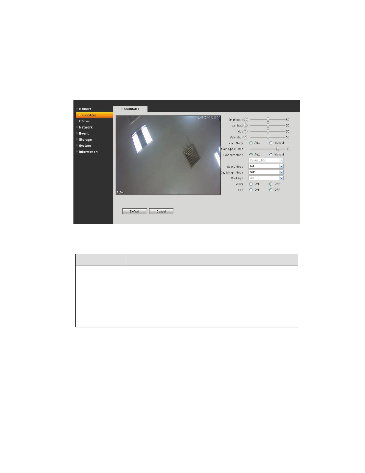
Here you can view device property information. Slight differences may be found due to different IPC
series. The setups become valid immediately after you set. See Figure 4-1.
Figure 4-1
Please refer to the following sheet for detailed information.
Parameter Function
Brightness It is to adjust monitor window bright. The value ranges from 0 to
100. The default value is 50.
The larger the number, the bright the video is. When you input
the value here, the bright section and the dark section of the
video will be adjusted accordingly. You can use this function
when the whole video is too dark or too bright. Please note the
video may become hazy if the value is too high. The
recommended value ranges from 40 to 60.
11
Page 79

Contrast It is to adjust monitor window contrast. The value ranges from 0
to 100. The default value is 50.
The larger the number, the higher the contrast is. You can use
this function when the whole video bright is OK but the contrast
is not proper. Please note the video may become hazy if the
value is too low. If this value is too high, the dark section may
lack brightness while the bright section may over exposure .The
recommended value ranges from 40 to 60.
Hue It is to adjust monitor window hue. The value ranges from 0 to
100. The default value is 50.
The input value will adjust the hue but has no effect on the
general brightness of the whole video. Such as turn the red
color to the blue color. There is a default value according to the
sensitization of the sensor. Usually you do not need to do some
major setup. The recommended value ranges from 40 to 60.
Saturation It is to adjust monitor window saturation. The value ranges from
0 to 100. The default value is 50.
The larger the number, the strong the color is. This value has
no effect on the general brightness of the whole video. The
video color may become too strong if the value is too high. For
the grey part of the video, the distortion may occur if the white
balance is not accurate. Please note the video may not be
attractive if the value is too low. The recommended value
ranges from 40 to 60.
Gain Mode
Gain Adjust
There are two options: manual/auto.
The gain adjust is to set the gain value. The default value may
vary due to different device models. The smaller the value, the
low the noise. But the brightness is also too low in the dark
environments. It can enhance the video brightness if the value
is high. But the video noise may become too clear.
Exposure Mode There are two modes: Auto exposure (AE) and Manual
exposure (ME).
There are several values for the manual exposure mode. You
can select from the dropdown list, It support the long exposure.
It supports customized setup too. The device can auto exposure
according to the exposure time you set here. The value ranges
from 0.1 to 80ms. The exposure time is fixed if the max and min
value are the same.
Customized value: System can auto exposure according to the
value you set here. The value ranges from 0.1 to 80ms.
12
Page 80

Auto Iris Before the setup, please make sure you have installed the auto
iris.
You can check the box before ON to enable this function. The
auto iris may change if the light becomes different.
When you disable this function, the iris is at the max. System
does not add the auto iris function in the exposure control.
This function is on by default.
Some series product does not support this function.
Scene Mode It is to set the white balance mode. It has effect on the general
hue of the video. This function is on by default.
You can select the different scene mode such as auto, sunny,
cloudy, home, office, night, disable and etc to adjust the video
to the best quality.
z Disabled: The white balance function is off. The video will
be output at the original color.
z Auto: The auto white balance is on. System can auto
compensate the color temperature to make sure the vide
color is proper.
z Sunny: The threshold of the white balance is in the sunny
mode.
z Night: The threshold of the white balance is in the night
mode.
z Customized: You can set the gain of the red/blue channel.
The value reneges from 0 to 100.
Day/Night Mode It is to set device color and the B/W mode switch. The default
setup is on.
z Color: Device outputs the color video.
z Auto: Device auto select to output the color or the B/W
video according to the device feature (The general bright of
the video or there is IR light or not.)
z B/W: The device outputs the black and white video.
z Switch by periods: You can se the day/night mode switch
time. For example, you can set the sunrise time as
06:00:00 and the sunset time as 18:00:00. The video in the
specified period will be color while the video in the rest
period will be black and white.
13
Page 81
BLC This function can make the target clearer. It can make the
details of the dark section become clear when the background
is too bright.
This function is disabled by default.
Please note only the IPC-HF3101//IPC-HFW3101C series
product supports the WDR function. The default setup is
WDR and the value ranges from 1 to 100. When you switch the
camera from no-WDR mode to the WDR mode, system may
lose several seconds record video. It does not support long-time
exposure when it is in WDR mode.
Flip It is to switch video up and bottom limit.
This function is disabled by default.
Mirror It is to switch video left and right limit.
This function is disabled by default.
Some series product does not support this function.
4.1.2 Video
4.1.2.1 Video bit stream
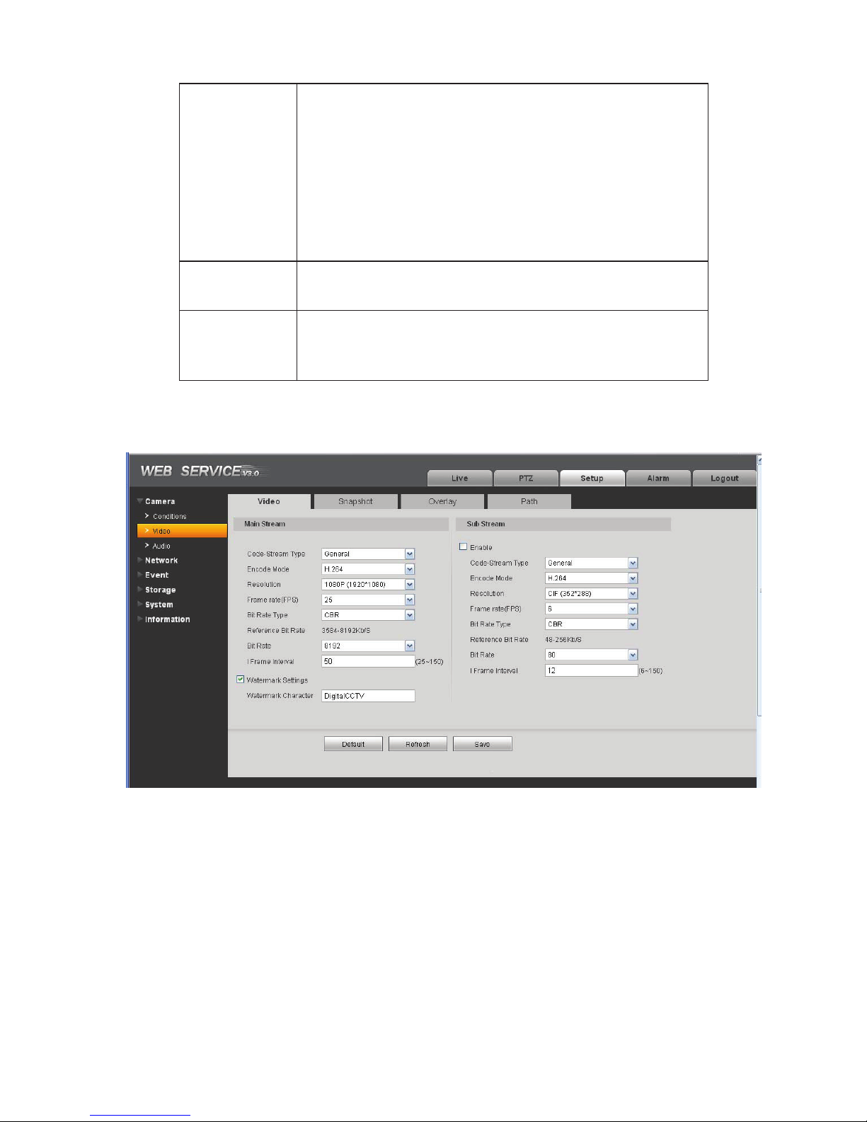
The video bit stream interface is shown as below. See Figure 4-2.
Please refer to the following sheet for detailed information.
Figure 4-2
14
Page 82

Parameter Function
Main
stream
Bit stream type
It includes general stream, motion stream and alarm
stream. You can select different encode frame rates
form different recorded events.
System supports active control frame function (ACF). It
allows you to record in different frame rates.
For example, you can use high frame rate to record
important events, record scheduled event in lower
frame rate and it allows you to set different frame rates
for motion detection record and alarm record.
Encode mode
There are three options: H.264(main profile standard,
H.264B(baseline standard˅encode and MJPG encode.
z The H.264 and H.264B both are H264 bit stream.
H.264 is the Main Profile encode and the H.264B is
the Baseline Profile encode mode. H.264B is for
Blackberry cell phone to realize the monitor.
z MJPEG: In this encode mode, the video needs to
large bit stream to guarantee the video definition.
You can use the max bit stream value in the
recommend bit to get the better video output effect.
Resolution There are multiple resolutions. You can select from the
dropdown list.
For each resolution, the recommended bit stream value
is different.
Frame Rate
PAL: 125f/sˈNTSC: 130f/s..
The frame rate may vary due to different resolutions.
Bit Rate Type
Recommended
Bit
Bit Rate
There are two options: VBR and CBR.
Please note, you can set video quality in VBR mode.
Recommended bit rate value according to the resolution
and frame rate you have set.
z
In CBR, the bit rate here is the max value. In dynamic
video, system needs to low frame rate or video quality
to guarantee the value.
z
The value is null in VBR mode.
z
Please refer to recommend bit rate for the detailed
information.
I Frame Here you can set the P frame amount between two I
frames. The value ranges from 1 to 150. Default value
is 50.
Recommended value is frame rate *2.
15
Page 83

Parameter Function
Watermark
This function allows you to verify the video is tampered
or not.
Here you can select watermark bit stream, watermark
mode and watermark character. Default character is
DigitalCCTV. The max length is 85-digit. The character
can only include number, character and underline.
Sub
stream
Enable
Bit stream type
Encode mode
Please check the box here to enable extra stream
function.
This function is enabled by default.
General bit stream.
There are three options: H.264(main profile standard,
H.264B(baseline standard˅encode and MJPG encode.
z The H.264 and H.264B both are H264 bit stream.
H.264 is the Main Profile encode and the H.264B is
the Baseline Profile encode mode. H.264B is for
Blackberry cell phone to realize the monitor. You
need to enable the sub stream function in your
camera and set the resolution as CIF. Then you
can monitor via the Blackberry cell phone.
z MJPEG: In this encode mode, the video needs to
large bit stream to guarantee the video definition.
You can use the max bit stream value in the
recommend bit to get the better video output effect.
Resolution There are multiple resolutions. You can select from the
dropdown list.
For each resolution, the recommended bit stream value
is different.
Frame Rate
Bit Rate Type
Recommended
Bit
Bit Rate
PAL: 125f/sˈNTSC: 130f/s..
The frame rate may vary due to different resolutions.
There are two options: VBR and CBR.
Please note, you can set video quality in VBR mode.
Recommended bit rate value according to the resolution
and frame rate you have set.
z
In CBR, the bit rate here is the max value. In dynamic
video, system needs to low frame rate or video quality
to guarantee the value.
z
The value is null in VBR mode.
z
Please refer to recommend bit rate for the detailed
information.
16
Page 84
Parameter Function
I Frame Here you can set the P frame amount between two I
frames. The value ranges from 1 to 150. Default value
is 50.
Recommended value is frame rate *2.
4.1.2.2 Snapshot
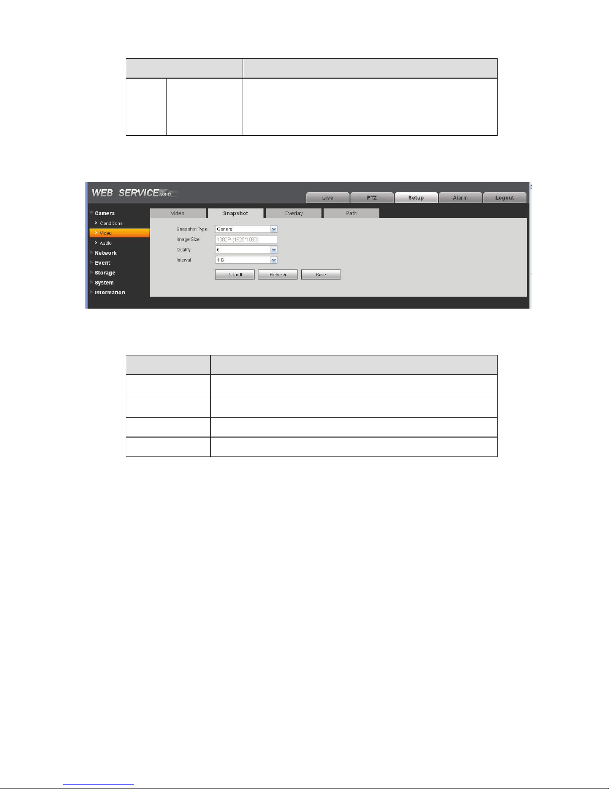
The snapshot interface is shown as in Figure 4-3.
Figure 4-3
Please refer to the following sheet for detailed information.
Parameter Function
Snapshot type
Image size It is the same with the resolution of the main stream.
Quality
Interval
There are two modes: general (schedule) and Event
(activation).
It is to set the image quality. There are six levels.
It is to set snapshot frequency. The value ranges from 1s to 7s.
4.1.2.3 Video Overlay
The video overlay interface is shown as in Figure 4-4.
17
Page 85
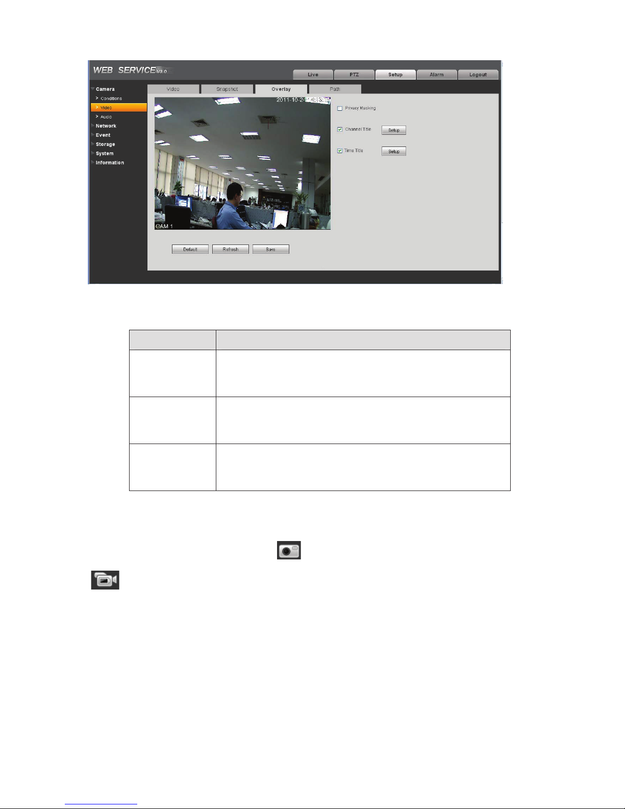
Figure 4-4
Please refer to the following sheet for detailed information.
Parameter Function
Privacy mask
z
Here you can privacy mask the specified video in the monitor
video.
z
System max supports 4 privacy mask zones.
Time Title
z
You can enable this function so that system overlays time
information in video window.
z
You can use the mouse to drag the time tile position.
Channel Title
z
You can enable this function so that system overlays channel
information in video window.
z
You can use the mouse to drag the channel tile position.
4.1.2.4 Path
The storage path interface is shown as in Figure 4-5.
Here you can set snap image saved path (
(
in the preview interface).The default setup is C:\PictureDownload.
Please click the Save button to save current setup.
in the preview interface) and the record storage path
18
Page 86
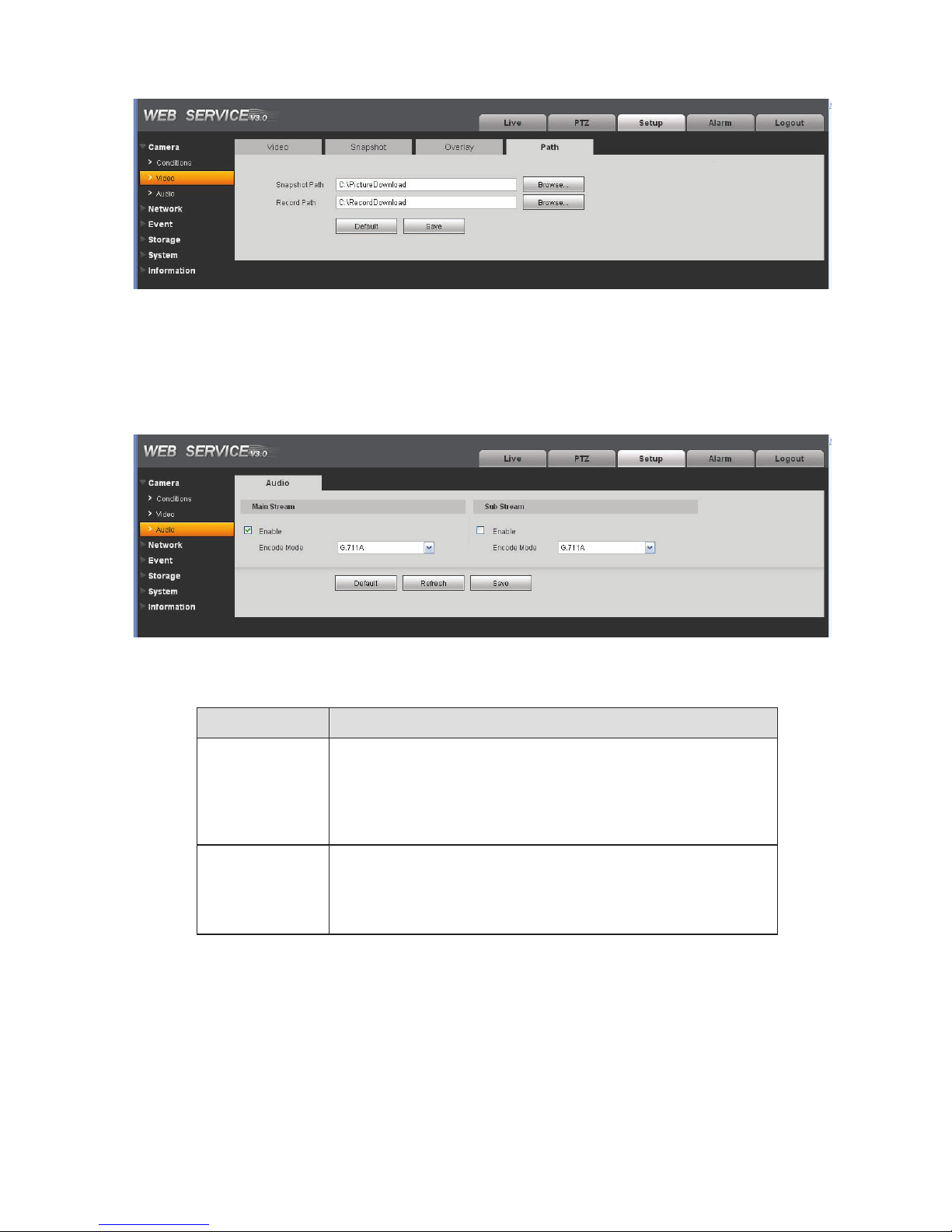
Figure 4-5
4.1.3 Audio
Please note some series product does not support this function.
The audio interface is shown as below. See Figure 4-6.
Figure 4-6
Please refer to the following sheet for detailed information.
Parameter Function
Audio enable Main stream: Recorded file only contains video by default. You
need to check the audio box here to enable audio function.
Sub (Extra) stream: Recorded file only contains video by
default. You need to check the audio box here to enable audio
function.
Encode mode The encode mode of the main stream and extra stream include
PCM, G.711A and G.711Mu.
The setup here is for audio encode mode and the bidirectional
talk encode both.
19
Page 87
1HWZRUN
4.2.1 TCP/IP
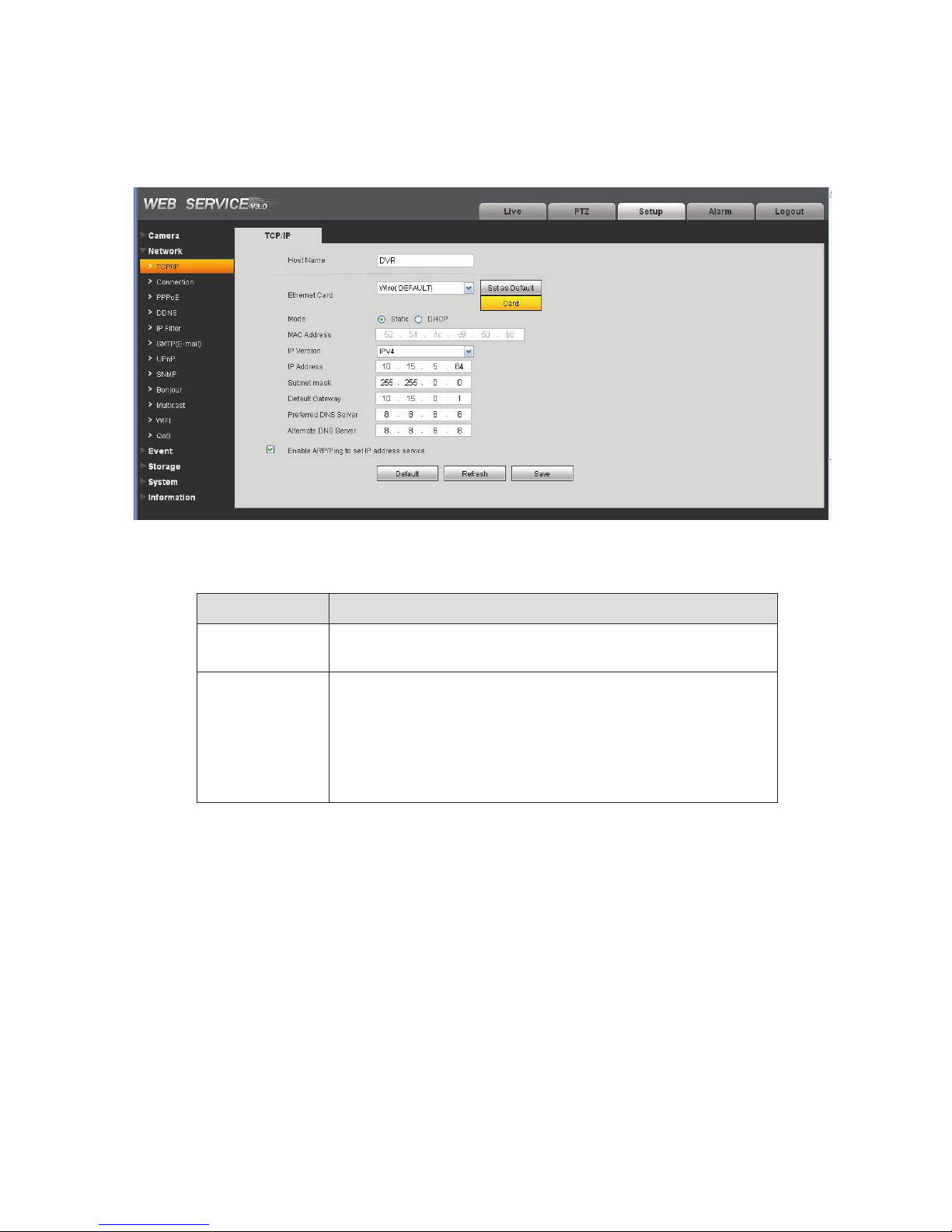
The TCP/IP interface is shown as in Figure 4-7.
Figure 4-7
Please refer to the following sheet for detailed information.
Parameter Function
Host Name It is to set current host device name. It max supports 32-digit
character.
Ethernet Card Please select the Ethernet port. It is for the wire LAN by default.
Please note for the -W series product, it has the wireless
network card, and you can modify the default Ethernet port
setup.
Please note the device needs to reboot to activate the new
setup once you modify the default setup.
20
Page 88

Mode There are two modes: static mode and the DHCP mode.
z The IP/submask/gateway are null when you select the
DHCP mode to auto search the IP.
z If you select the static mode, you need to set the
IP/submask/gateway manually.
z If you select the DHCP mode, you can view the
IP/submask/gateway from the DHCP.
z If you switch from the DHCP mode to the static mode, you
need to reset the IP parameters.
z Besides, IP/submask/gateway and DHCP are read-only
when the PPPoE dial is OK.
Mac Address It is to display hose Mac address.
IP Version It is to select IP version. IPV4 or IPV6.
You can access the IP address of these two version.
IP Address Please use the keyboard to input the corresponding number to
modify the IP address and then set the corresponding subnet
mask and the default gateway.
Preferred DNS DNS IP address.
Alternate DNS Alternate DNS IP address.
Enable
ARP/Ping set
device IP
address service.
You can use ARP/Ping command to modify or set the device IP
address if you know the device MAC address.
Before the operation, please make sure the IPC and the PC in
the same LAN. This function is on by default.
You can refer to the steps listed below.
Step 1: Get an IP address. Set the IPC and the PC in the same
LAN.
Step 2: Get the physical address from the label of the IPC.
Step 3: Go to the Run interface and then input the following
commands.
arp–s<IPAddress><MAC>
ping–l480–t<IPAddress>
Suchas˖arpͲs192.168.0.12511Ͳ40Ͳ8cͲ18Ͳ10Ͳ11
pingͲl480Ͳt192.168.0.125
Step 4: Reboot the device.
Step 5: You can see the setup is OK if you can see there are
output information such as “Reply from 192.168.0.125 …” from
the command output lines. Now you can close the command
line.
Step 6: Open the browse and then input http://<IP addres>.
Click the Enter button, you can access now.
21
Page 89
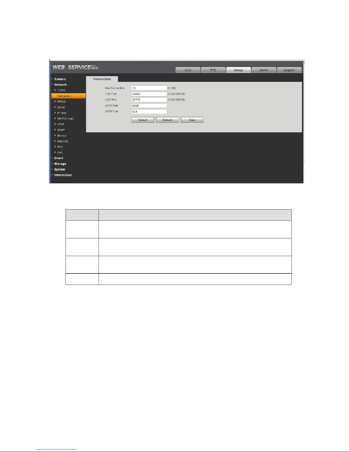
4.2.2 Connection
The connection interface is shown as in Figure 4-8.
Figure 4-8
Please refer to the following sheet for detailed information.
Parameter Function
Max
connection
TCP port The default value is 37777. You can input the actual port number if
UDP port The default value is 37778. You can input the actual port number if
HTTP port The default value is 80. You can input the actual port number if necessary.
It is the max Web connection for the same device. The value ranges from 1
to 20. The max connection amount is 20.
necessary.
necessary.
22
Page 90
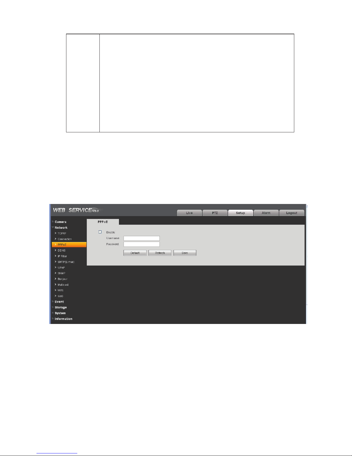
RTSP port The default value is 554. Rtsp streay query format is:
Main stream:
rtsp://username:password@ip:port/cam/realmonitor?channel=1&subtype=0
Sub stream:
rtsp://username:password@ip:port/cam/realmonitor?channel=1&subtype=1
You need to input the following four items manually.
Username/password/IP and port.
The IP is device IP and the port default value is 554. You can leave it in
blank if it is the default value.
You do not need to input the user name and password if you do not need
to the verification. Such as:
rtsp://ip:port/cam/realmonitor?channel=1&subtype=0
4.2.3 PPPoE
The PPPoE interface is shown as in Figure 4-9.
Input the PPPoE user name and password you get from the IPS (internet service provider) and enable
PPPoE function. Please save current setup and then reboot the device to get the setup activated.
Device connects to the internet via PPPoE after reboot. You can get the IP address in the WAN from
the IP address column.
Please note, you need to go to the IP address item to via the device current device information.
You can access the client-end via this address.
Figure 4-9
4.2.4 DDNS
The DDNS interface is shown as in Figure 4-10.
23
Page 91
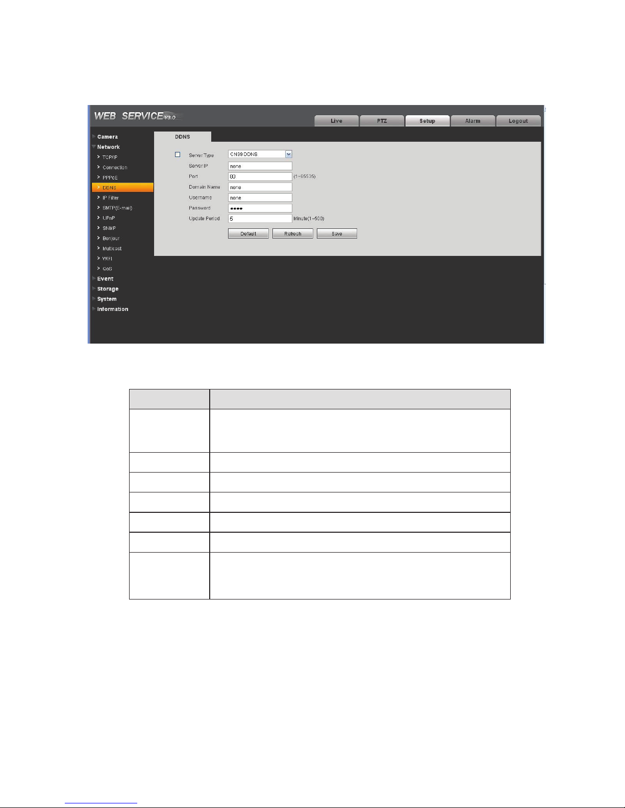
The DDNS is to set to connect the various servers so that you can access the system via the server.
Please go to the corresponding service website to apply a domain name and then access the system
via the domain. It works even your IP address has changes.
Figure 4-10
Please refer to the following sheet for detailed information.
Parameter Function
Server Type You can select DDNS protocol from the dropdown list and then
enable DDNS function. The private DDNS protocol means you
use your self-defined private protocol to realize DDNS function.
Server IP DDNS server IP address
Server Port DDNS server port.
Domain Name Your self-defined domain name.
User The user name you input to log in the server.
Password The password you input to log in the server.
Update period zDevice sends out alive signal to the server regularly.
z
You can set interval value between the device and DDNS
server here.
4.2.5 IP filter
The IP filter interface is shown as in Figure 4-11.
24
Page 92
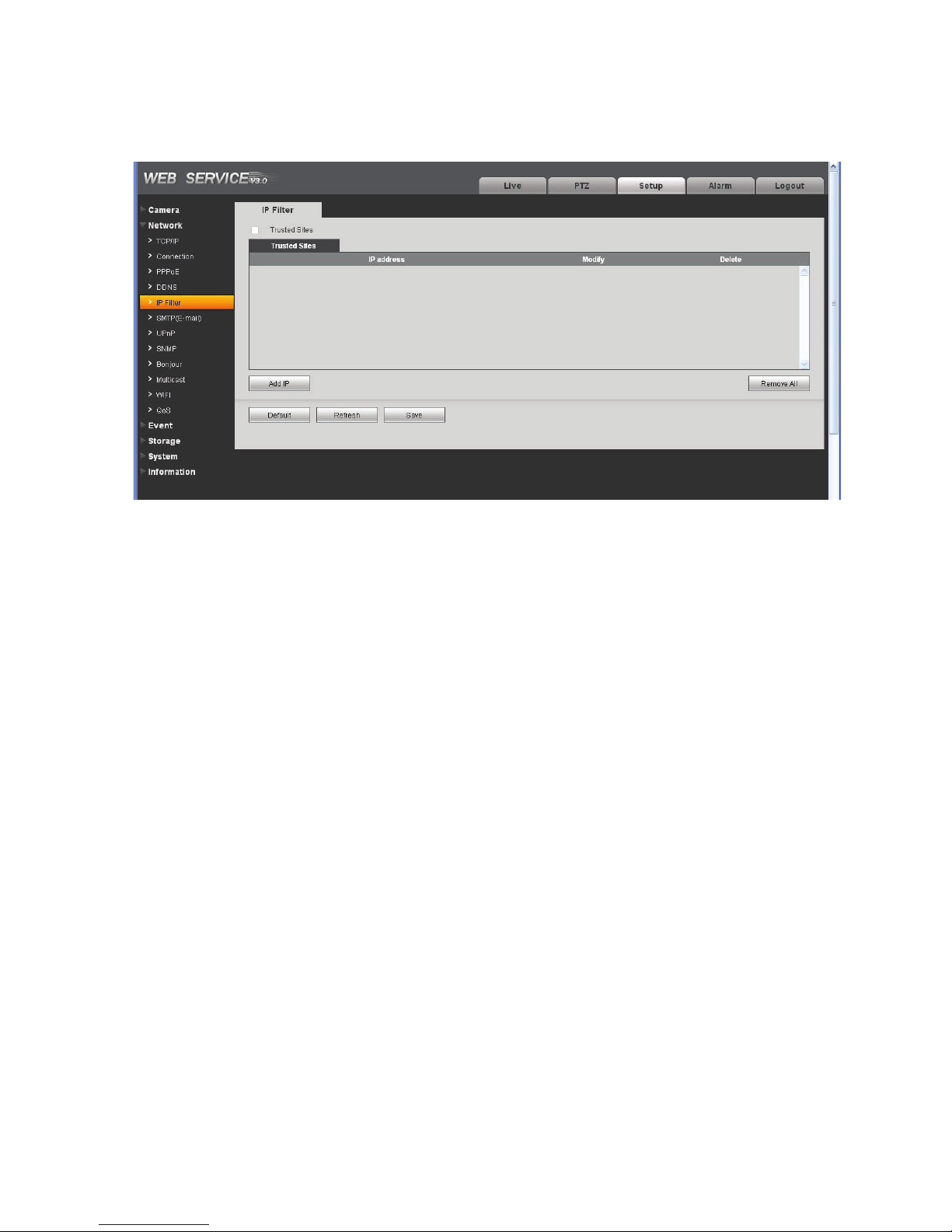
You can enable IP filter function so that some specified IP user can access the IPC.
˄
˅
You can add IP address or IP address section.
If you do not check the box here, it means there is on access limit.
Figure 4-11
4.2.6 SMTP
The SMTP interface is shown as in Figure 4-12.
e-mail
25
Page 93
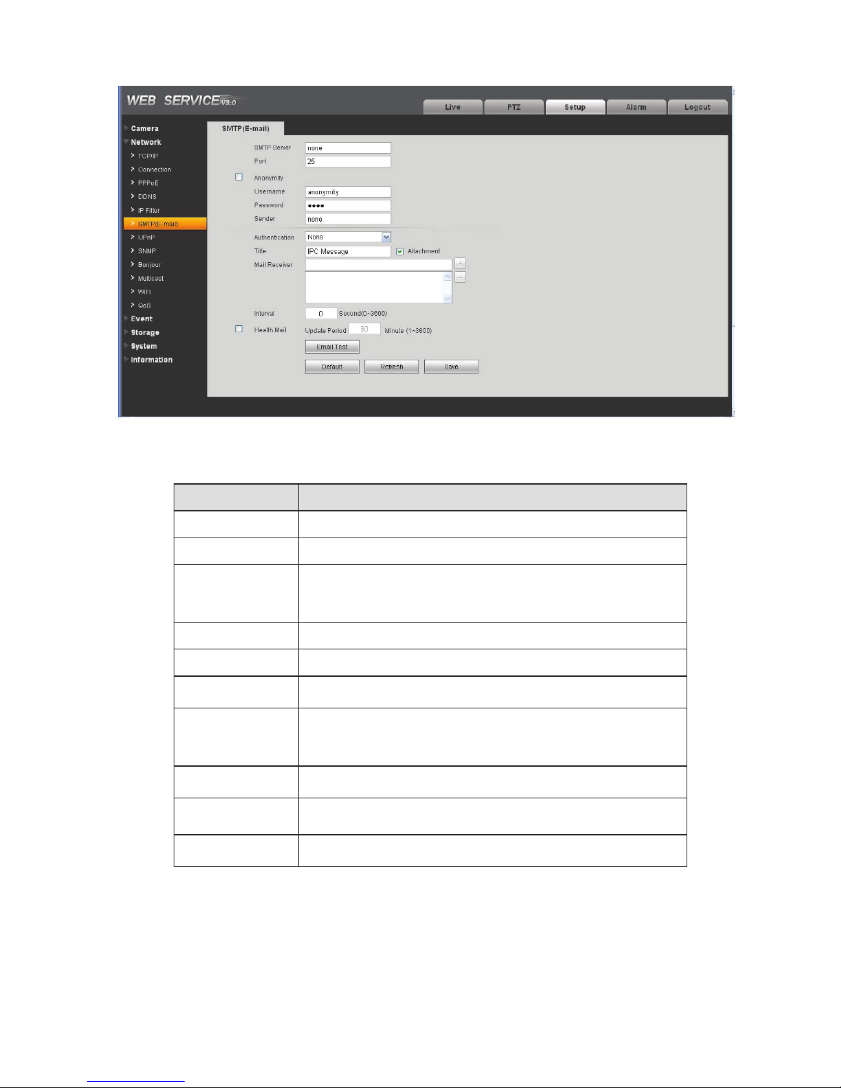
Figure 4-12
Please refer to the following sheet for detailed information.
Parameter Function
SMTP Server
Port Default value is 25. You can modify it if necessary.
Anonymity For the server supports the anonymity function. You can auto
User Name
Password
Sender
Input server address and then enable this function.
login anonymously. You do not need to input the user name.
password and the sender information.
The user name of the sender email account.
The password of sender email account.
Sender email address.
Authentication
(Encryption
mode)
Title (Subject)
Attachment
Mail receiver
You can select SSL or none.
Input email subject here.
System can send out the email of the snapshot picture once
you check the box here.
Input receiver email address here. Max three addresses.
26
Page 94

Parameter Function
Interval
Health mail
enable
Update period
(interval)
Email test
The send interval ranges from 0 to 3600 seconds. 0 means
there is no interval.
Please note system will not send out the email immediately
when the alarm occurs. When the alarm, motion detection or
the abnormity event activates the email, system sends out the
email according to the interval you specified here. This
function is very useful when there are too many emails
activated by the abnormity events, which may result in heavy
load for the email server.
Please check the box here to enable this function.
This function allows the system to send out the test email to
check the connection is OK or not.
Please check the box to enable this function and then set the
corresponding interval.
System can send out the email regularly as you set here.
The system will automatically sent out a email once to test the
connection is OK or not .Before the email test, please save
the email setup information.
4.2.7 UPnP
It allows you to establish the mapping relationship between the LAN and the public network.
Here you can also add, modify or remove UPnP item. See Figure 4-13.
In the Windows OS, From Start->Control Panel->Add or remove programs. Click the “Add/Remove
Windows Components” and then select the “Network Services” from the Windows Components Wizard.
Click the Details button and then check the “Internet Gateway Device Discovery and Control client” and
“UPnP User Interface”. Please click OK to begin installation.
Enable UPnP from the Web. If your UPnP is enabled in the Windows OS, the IPC can auto detect it via
the “My Network Places”
27
Page 95
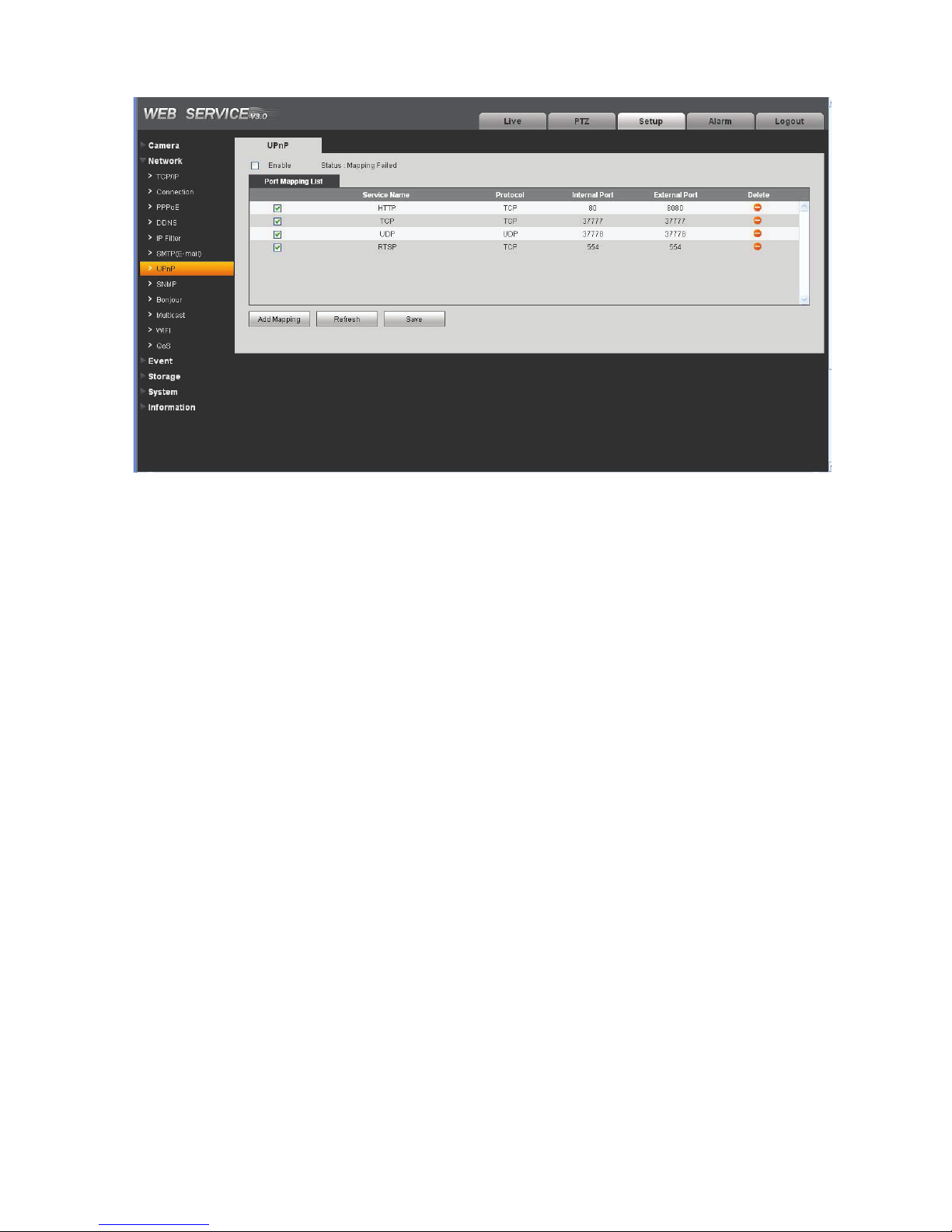
Figure 4-13
4.2.8 SNMP
The SNMP interface is shown as in Figure 4-14.
The SNMP allows the communication between the network management work station software and the
proxy of the managed device. Please install the software such as MG MibBrowser 8.0c software or
establish the SNMP service before you use this function. You need to reboot the device to activate the
new setup.
28
Page 96
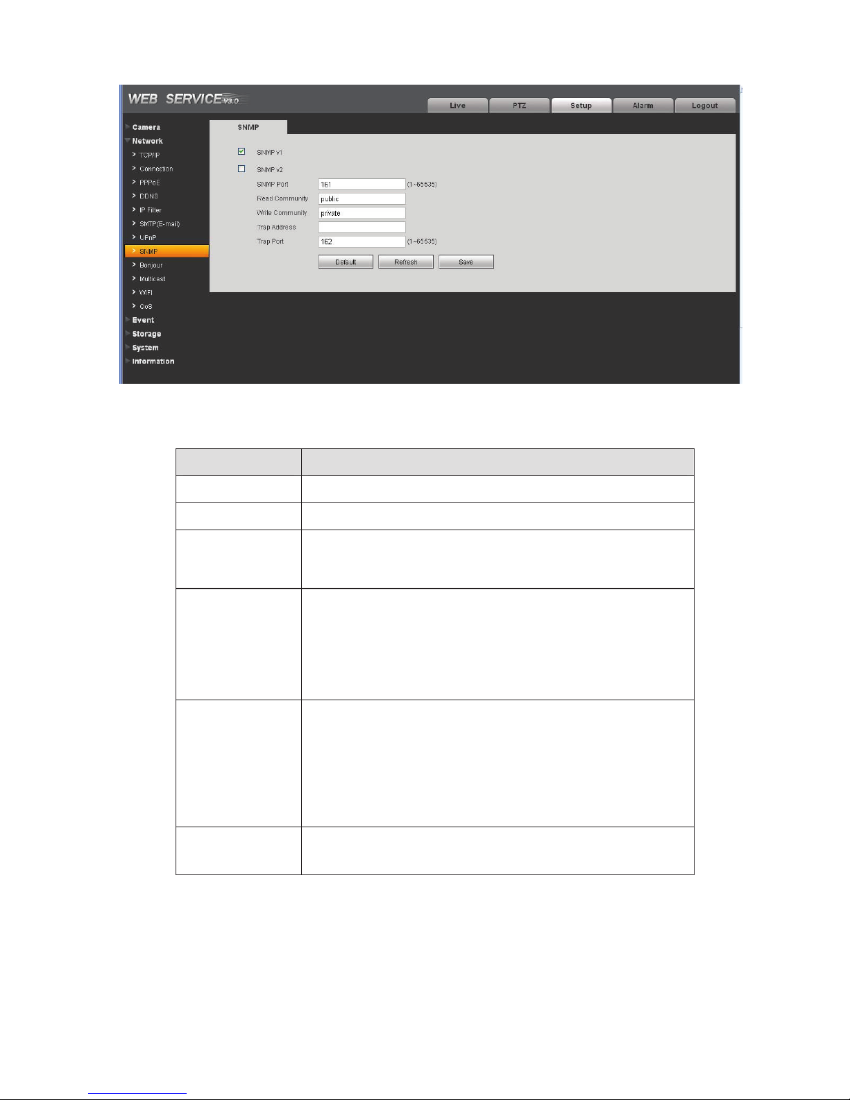
Figure 4-14
Please refer to the following sheet for detailed information.
Parameter Function
SNMP V1
SNMP V2 System only processes the information of V2.
SNMP Port The listening port of the proxy program of the device. It is a
Read Community
Write Community
Trap address
System only processes the information of V1.
UDP port not a TCP port. The value ranges from 1 to 65535.
The default value is 161
It is a string. It is a command between the manage process
and the proxy process. It defined the authentication, access
control and the management relationship between one proxy
and one group of the managers. Please make sure the device
and the proxy are the same.
The read community will read all the objects the SNMP
supported in the specified name. The default setup is public.
It is a string. It is a command between the manage process
and the proxy process. It defined the authentication, access
control and the management relationship between one proxy
and one group of the managers. Please make sure the device
and the proxy are the same.
The read community will read/write/access all the objects the
SNMP supported in the specified name. The default setup is
write.
The destination address of the Trap information from the
proxy program of the device.
29
Page 97
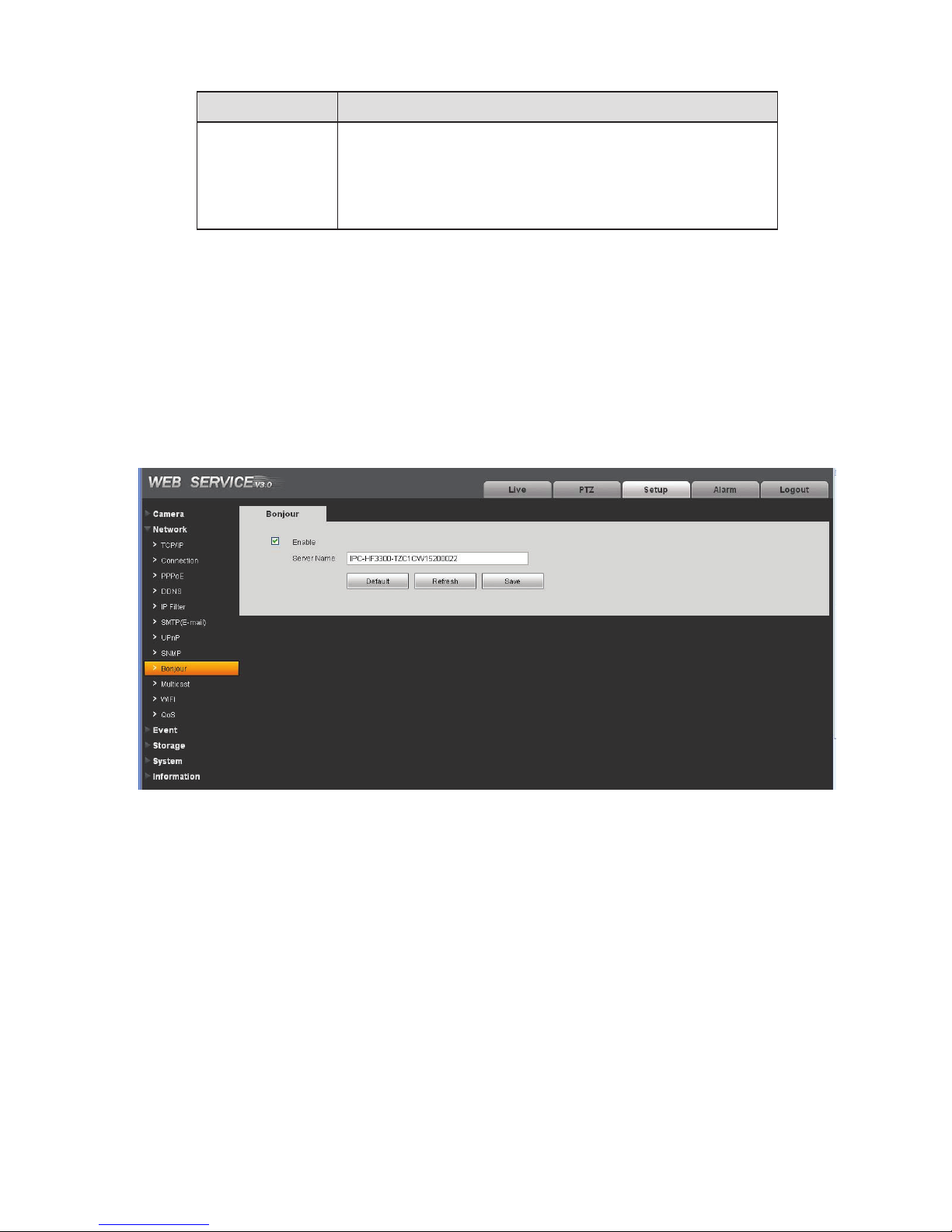
Parameter Function
Trap port
The destination port of the Trap information from the proxy
program of the device. It is for the gateway device and the
client-end PC in the LAN to exchange the information. It is a
non-protocol connection port. It has no effect on the network
applications. It is a UDP port not TCP port. The value ranges
from 1 to 165535. The default value is 162.
4.2.9 Bonjour
The Bonjour interface is shown as below. See Figure 4-15.
Bonjour is based on the multicast DNS service from the Apple. The Bonjour device can automatically
broadcast its service information and listen to the service information from other device.
You can use the browse of the Bonjour service in the same LAN to search the IPC device and then
access if you do not know the IPC information such as IP address.
You can view the server name when the IPC is detected by the Bonjour. Please note the safari browse
support this function. Click the “Display All Bookmarks: and open the Bonjour, system can auto detect
the IPC of the Bonjour function in the LAN.
4.2.10 Multicast
The multicast interface is shown as in Figure 4-16.
Multicast is a transmission mode of data packet. When there is multiple-host to receive the same data
packet, multiple-cast is the best option to reduce the broad width and the CPU load. The source host
Figure 4-15
30
Page 98
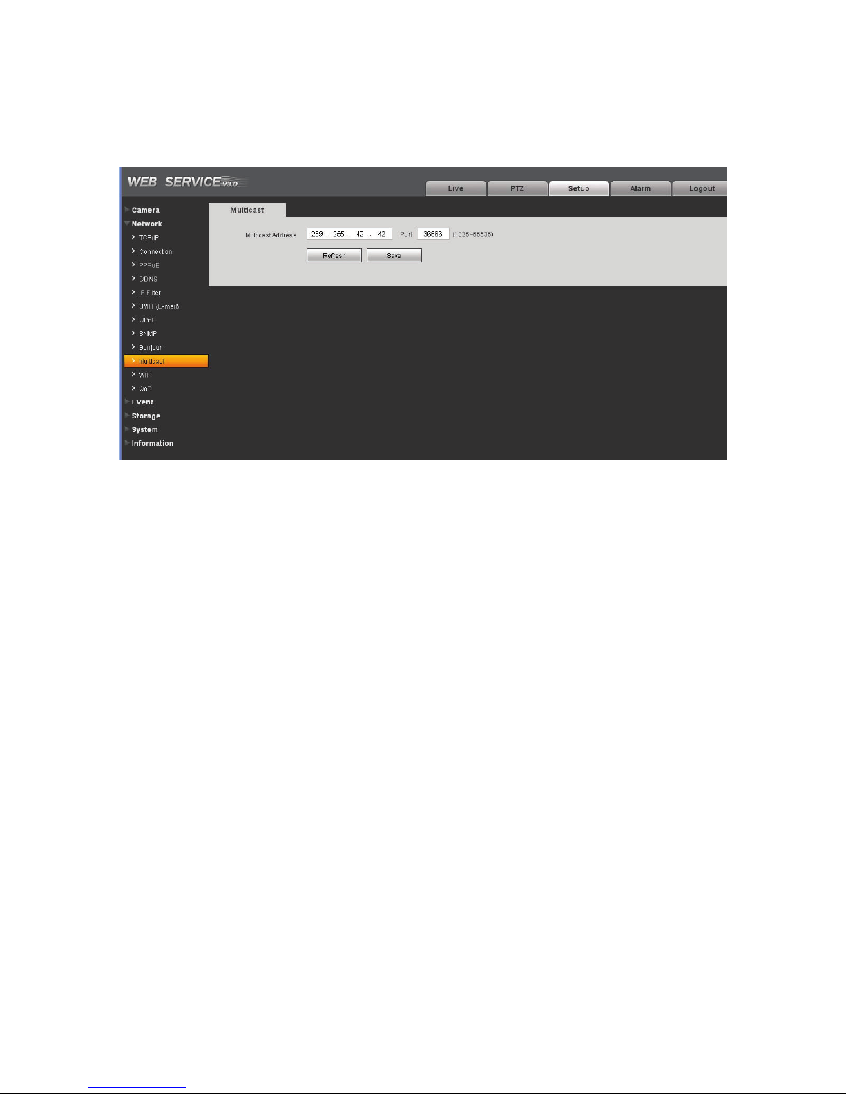
can just send out one data to transit. This function also depends on the relationship of the group
member and group of the outer.
Here you can set multicast address and port. You also need to go to Live interface to set the protocol as
Multicast.
Figure 4-16
4.2.11 WIFI
Please note this function is for the device of WIFI module.
The WIFI interface is shown as in Figure 4-17.
31
Page 99
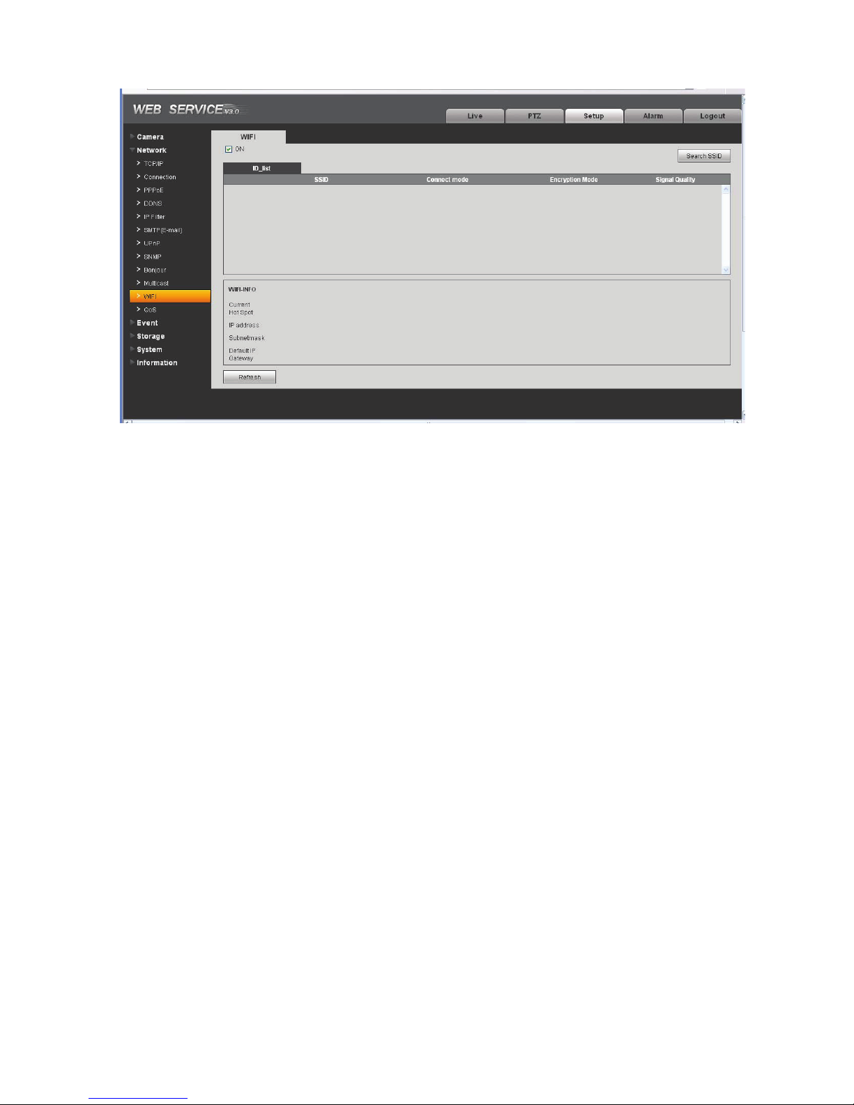
Figure 4-17
Please check the box to enable WIFI function and then click the Search SSID button. Now you can view
all the wireless network information in the following list. Double click a name to connect to it. See Figure
4-18.
32
Page 100
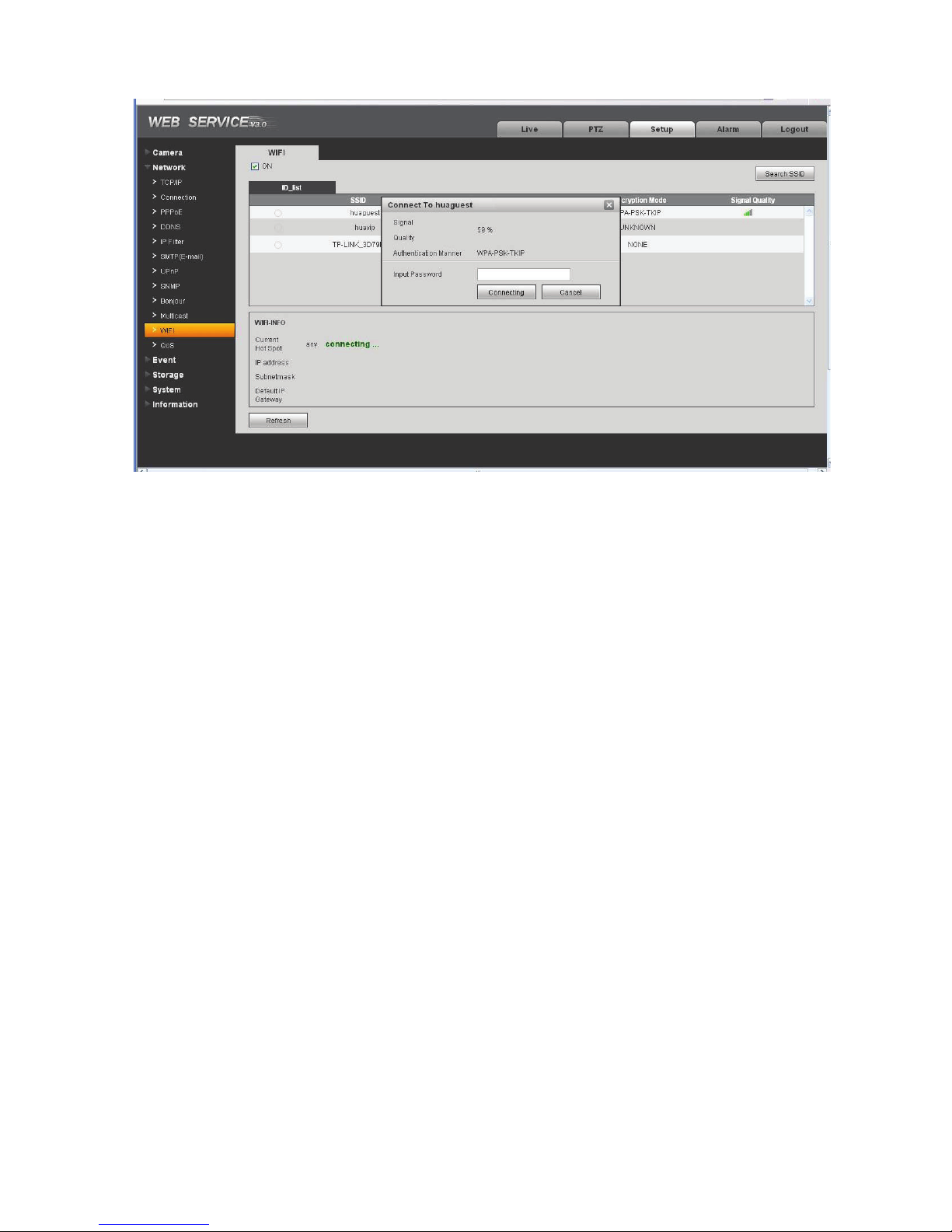
Figure 4-18
4.2.12 Qos
The QoS interface is shown as below. See Figure 4-19.
Qos (Quality of Service) is network security mechanism. It is a technology to fix the network delay and
jam problem and etc. For the network service, the quality of service includes the transmission bandwidth,
delay, the packet loss and etc. We can guarantee the transmission bandwidth, lower the delay, reduce
the loss of the data packet and anti-dither to enhance the quality.
We can set the DSCP (Differentiated Services Code Point) of the IP to distinguish the data packet so
that the router or the hub can provide different services for various data packets. It can select the
different queues according to the priority of the packets and select the bandwidth of the each queue. It
can also discard at the different ratio when the broad bandwidth is jam.
33
 Loading...