

Page 1
ClearSpan™
Storage Master Elite Garages
30' Wide
CLEARSPAN™ GARAGES
©2016 ClearSpan™
All Rights Reserved. Reproduction
is prohibited without permission.
Revision date: 05.20.16
Photo shows a different but similar model.
STK# DIMENSIONS
107771 30' W x 15' H x 24' L
107772 30' W x 15' H x 28' L
107773 30' W x 15' H x 36' L
107774 30' W x 15' H x 44' L
1
Page 2

CLEARSPAN™ GARAGES
READ THIS DOCUMENT BEFORE YOU BEGIN
Thank you for purchasing this ClearSpan™ shelter. When
properly assembled and maintained, this product will
provide years of reliable service. These instructions include
helpful hints and important information needed to safely
assemble and properly maintain the shelter. Please read
these instructions before you begin.
If you have any questions during the assembly, contact
Customer Service for assistance.
SAFETY PRECAUTIONS
LOCATION
Choosing the proper location is an important step before
you begin to assemble the structure.
The following suggestions and precautions will help you
determine whether your selected location is the best
location.
• Never erect the structure under power lines.
• Identify whether underground cables and pipes are
present before preparing the site or anchoring the
structure.
• Location should be away from structures that could
cause snow to drift on or around the building.
• Do not position the shelter where large loads such as
snow and ice, large tree branches, or other overhead
obstacles could fall.
SITE
• Wear eye protection.
• Wear head protection.
• Wear gloves when handling metal tubes.
• Use a portable GFCI (Ground Fault Circuit Interrupter)
when working with power tools and cords.
• Do not climb on the shelter or framing during or after
construction.
• Do not occupy the shelter during high winds,
tornadoes, or hurricanes.
• Provide adequate ventilation if the structure is
enclosed.
• Do not store hazardous materials in the shelter.
• Provide proper ingress and egress to prevent
entrapment.
QUICK START GUIDE
For a quick overview of this shelter and its components,
consult the Quick Start Guide at the back of these
instructions.
After choosing a location, proper preparation of the site is
essential. The following site characteristics will help ensure
the integrity of the structure.
• A level site is required. The site must be level to
properly and safely erect and anchor the structure.
If the site is not level, construct footings to provide
a secure base to assemble the structure. Pre-cast
concrete blocks, pressure-treated wood posts, or
poured footings are all acceptable when properly used.
• Drainage: Water draining off the structure and from
areas surrounding the site should drain away from the
site to prevent damage to the site, the structure, and
contents of the structure.
WARNING: The individuals assembling this structure
are responsible for designing and furnishing all
temporary bracing, shoring and support needed during
the assembly process. For safety reasons, those who
are not familiar with recognized construction methods
and techniques must seek the help of a qualified
contractor.
2
Revision date: 05.20.16
Page 3

ASSEMBLY PROCEDURE
Following the instructions as presented will help ensure
the proper assembly of your shelter. Failing to follow these
steps may result in an improperly assembled and anchored
shelter and will void all warranty and protection the owner
is entitled.
The steps outlining the assembly process are as follows:
1. Verify that all parts are included in the shipment. Notify
Customer Service for questions or concerns.
2. Read these instructions, the Must Read document, and
all additional documentation included with the shipment
before you begin assembling the shelter.
3. Gather the tools, bracing, ladders (and lifts), and
assistance needed to assemble the shelter.
4. Check the weather before you install the roof cover
and any panels (if equipped). Do not install covers or
panels on a windy or stormy day.
5. Re-evaluate the location and site based on the
information and precautions presented in the
documentation included with the shipment.
6. Lay out the site (if this has not been completed).
7. Assemble the frame components in the order they are
presented in these instructions.
8. Assemble the frame including the struts (if equipped).
9. Consult the Must Read document for anchoring
comments and instructions.
10. Assemble and install the cable assemblies (if
equipped). These are typically found on larger shelters.
Your shelter may include struts or other methods of
bracing attached during the frame assembly procedure.
(Some shelters do not require cables or struts.)
11. Install, tighten, and secure the end panels (if equipped)
and main cover. This applies to fabric covers that
stretch over the frame assembly.
12. Read the Care and Maintenance information at the end
of these instructions.
13. Complete and return all warranty information as
instructed.
LIST OF WORDS AND PHRASES
Before you begin, it is important to become familiar with the
words and phrases used in this instruction manual.
These words and phrases are common to most
ClearSpan™ shelters and identify the different parts of the
shelter. (Some are used in this document. Others may not
apply to this particular shelter.)
CLEARSPAN™ GARAGES
These terms describe the shipped parts and can also
be found on the materials list/spec sheets included with
the shipment. To aid in the assembly, read through the
following definitions before you begin to assemble your
shelter.
• Conduit: An assembly of pipes used to secure the
main cover and end panels (if equipped). Purlins and
some strut assemblies also consist of connected pipes
to form a conduit. Each pipe joint of a conduit assembly
is secured with a self-tapping Tek screw.
• Coupler or Fitting: A part of the frame assembly
where legs, purlins and rafter pipes are inserted and
secured. In most instances, 3-way and 4-way couplers
are used. In some larger applications, couplers are
used to secure the joints of the different rafter sections
during the assembly of the rafters. Some shelters do
not use couplers.
• Foot or Rafter Foot: The part attached to and found
at the base of the rafter or leg of the shelter.
Depending on the shelter, the foot is an optional
purchase. Some shelters do not offer an optional foot.
Some use 1-way connectors.
• Must Read Document: This document includes
building and shelter anchoring instructions, steps for
end wall reinforcement, safety precautions, and notices
and warnings. The Must Read document is sent with all
shelters and buildings. If you did not receive a Must
Read document, contact Customer Service to request
one.
• On-Center: Term used to describe a measurement
taken from the vertical center of the rafter or frame
member to the vertical center of another.
• Purlin: The pipe assembly that runs perpendicular to
the rafters or framework that supports the main cover.
Purlins are found on the sides and roof areas of the
assembled frame, are evenly spaced, and typically run
from the front to the back of the shelter.
• Plain or Straight Pipe: A term used to describe a pipe
that has the same diameter or width throughout its
entire length.
• Strut: A strut is usually a length of pipe with two
flattened ends and is used for diagonal bracing of the
shelter frame. A strut is typically secured to the frame
work by special brackets and bolts.
• Swaged End or Swaged Pipe: The term "swaged''
refers to the tapered end of the pipe or tube. Swaged
ends of a pipe can be inserted into couplers and the
straight ends of other pipes.
• Tek Screw: A self-tapping fastener used to secure pipe
joints and to fasten brackets to rafters.
Revision date: 05.20.16
3
Page 4
CLEARSPAN™ GARAGES
REQUIRED TOOLS
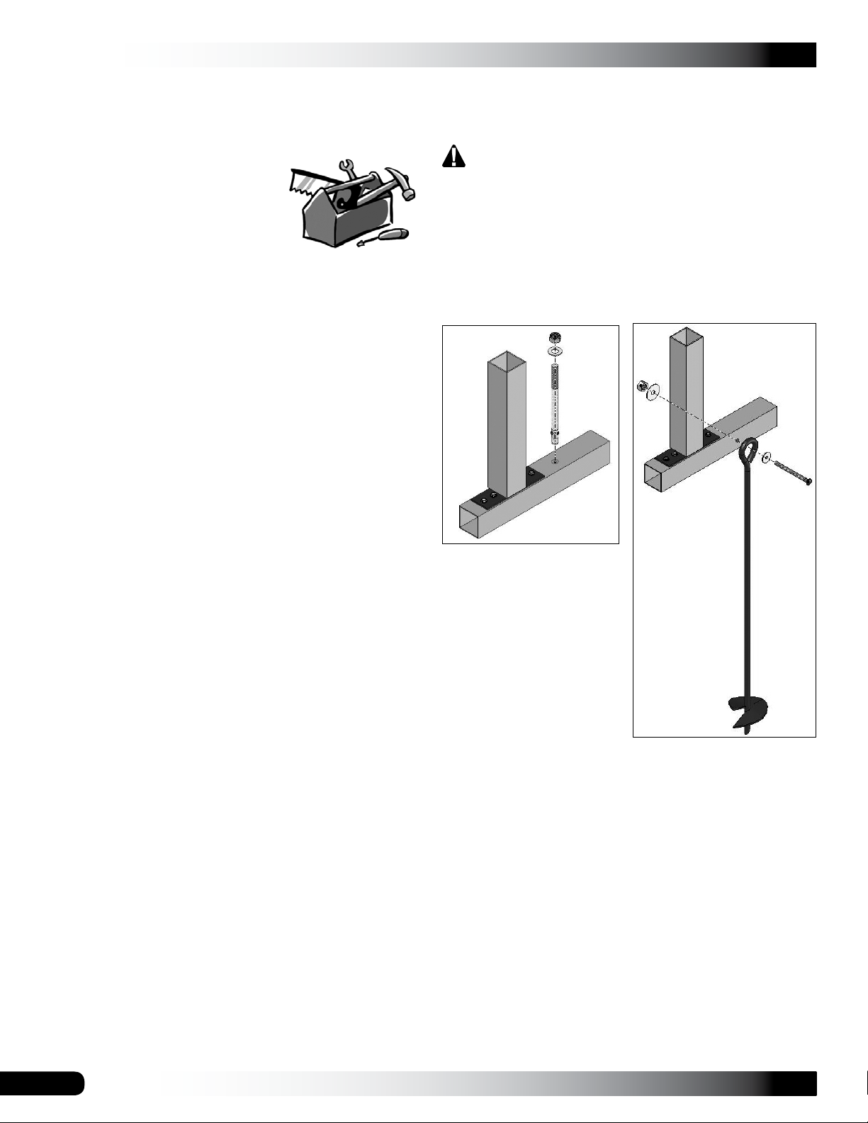
ANCHORING INSTRUCTIONS
The following list identifies the main tools needed to
assemble the shelter. Additional tools and supports may be
needed depending on the structure, location, and
application.
• Tape measure or
measuring device
• Chalk line (optional)
• Marker to mark locations on the pipes
• Variable speed drill and impact driver (cordless with
extra batteries works best)
• Metal-cutting tool for pipe
• Wrench, ratchet and socket (recommended)
• Hammers, gloves, ladders, work platforms, and other
machinery for lifting designed to work safely at the
height of the shelter.
UNPACK AND IDENTIFY PARTS
The following steps will ensure that you have all the
necessary parts before you begin to assemble the shelter.
Prior to assembling this shelter, please read the MUST
READ document included with the shipment.
WARNING: The anchor assembly is an integral part
of the shelter construction. Improper anchoring may
cause shelter instability and failure of the structure.
Failing to anchor the shelter properly will void the
manufacturer’s warranty and may cause serious injury
and damage.
The diagrams below illustrate two possible ways to properly
anchor the shelter to the site.
1. Unpack the contents of the shipment and place where
you can easily inventory the parts. Refer to the Bill of
Materials/Spec Sheets.
2. Verify that all parts listed on the Bill of Materials/Spec
Sheets are present. If anything is missing or you have
questions, consult the Pictorial Parts Guide and all
shelter diagrams for clarification, or contact Customer
Service.
NOTE: At this time, you do not need to open the plastic
bags containing the fasteners (if used).
Anchor System
for use on concrete.
Ground Anchor System
Install an anchor at each rafter leg along each side of the
frame.
The parts shown in the diagrams regarding anchor systems
are not included with the shelter. Contact Customer Service
at 1-800-245-9881 to purchase additional parts to anchor
the shelter.
4
Revision date: 05.20.16
Page 5
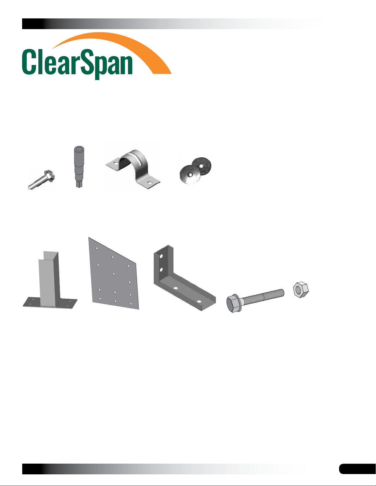
The following graphics and photos will help identify the
different parts used to construct your shelter.
(Some parts are not shown.)
CLEARSPAN™ GARAGES
FA4482B
Tek Screw
105088
1-Way Connector
100441
Nut Setter
Rafter Connection
QH1070
Pipe Strap
105087
Plate
102921
Neo-Bonded Washer
QH1330
Angled Bracket
FAG363B 3/8" Bolt
and FALB04B Nut
Revision date: 05.20.16
5
Page 6

CLEARSPAN™ GARAGES
OVERVIEW
This section describes assembling the garage frame. See
illustration below to identify main parts of shelter.
1. Locate required parts for each assembly procedure.
2. Assemble and position base rails.
3. Assemble rafters and frame.
ClearSpan™ Storage Master
Elite Garage
4. Square and anchor garage frame.
5. Install struts and shelter bracing.
6. Install end conduits and panels.
7. Attach main cover.
Inside Rafter
Main Cross
Member
End Rafter
Purlin
End Panel
Conduit
Diagram may show a different shelter length.
6
Bracing
Strut
Base Rail
Revision date: 05.20.16
Page 7
LAY OUT THE BUILDING SITE
CLEARSPAN™ GARAGES
ASSEMBLE AND POSITION BASE RAILS
After the site is prepared, marking the ground where the
shelter will be situated and identifying the location of
the shelter corners helps to square the frame after it is
assembled.
Taking these steps before assembling the shelter saves
time and ensures that the structure is positioned as
desired. The following procedure is a suggested method.
Its use depends on the size of the shelter, shelter
application, the footings, and the method used to anchor
the shelter.
This procedure may not be needed for shelters that include
a base rail. It can be used, however, as a guide when
positioning the frame on the site during assembly.
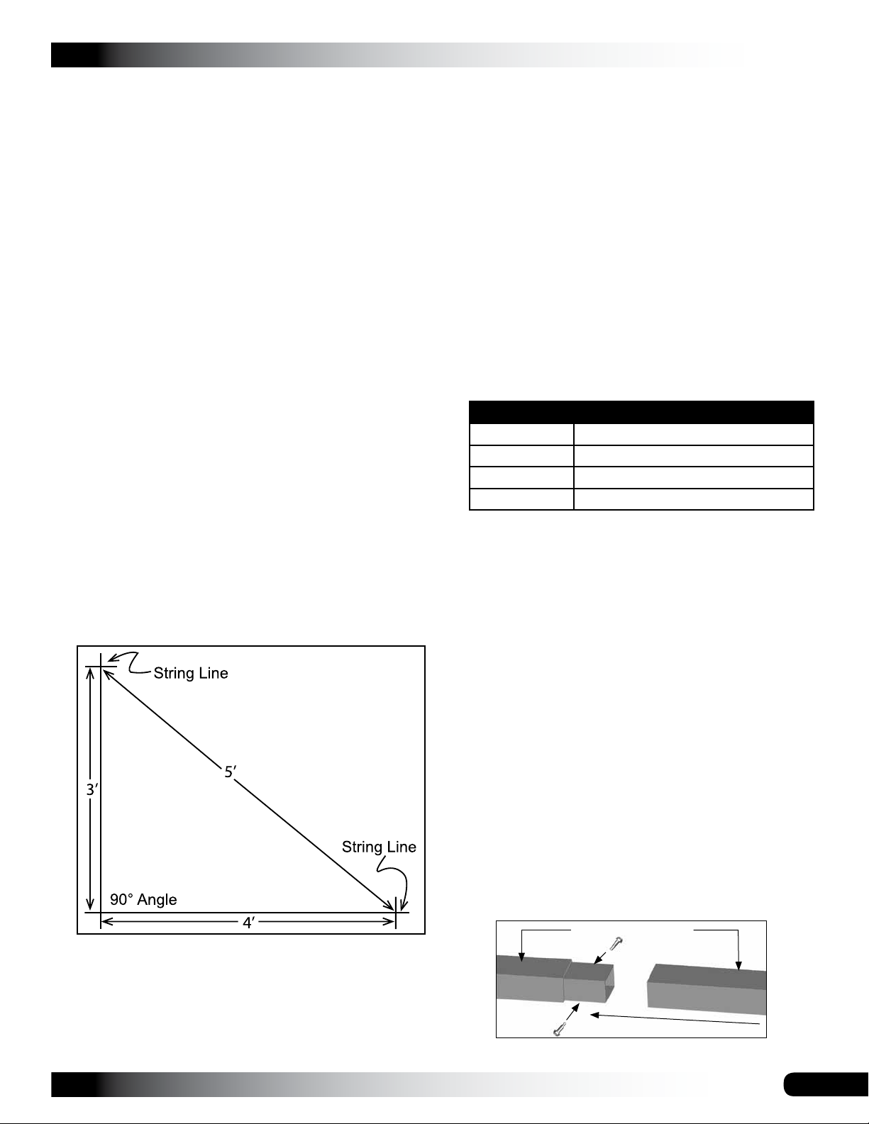
SQUARE THE SITE
1. Identify a corner where a building rafter or base rail
will be positioned, drive in a stake, and string a line the
exact width of the building and stake in place.
2. Sting a line at least as long as the building from the first
stake at 90°.
NOTE: A transit can be used to ensure an accurate 90°
angle, or the 3-4-5 rule can be used. Refer to diagram.
Using multiples of 3-4-5 such as 6-8-10 or 12-16-20
helps to maintain an accurate 90° angle.
3. After squaring the position of the building and placing
a stake at all corners, string a line between the stakes
to mark the base of the building.
NOTE: Assistance is required to assemble the garage
frame.
Gather the parts:
• Square tubing (see chart below) and 1-way connector
(105088)
• Tek screws and magnetic nut setter (3/8'' x 2-9/16")
The base rails consist of 2" x 3" square tubing (plain and
swaged) and run the length of the building. Each shelter
length has a different configuration of 2" x 3" square tubes
for the base rails. The tubing requirements for each base
rail for the different shelter lengths are listed below.
Consult Side Profile Diagrams in the Quick Start Section.
Shelter Length Tubing Requirement (per base rail)
24' 2 @ 123"S & 54"P
28' 2 @ 123"S & 102"P
36' 3 @ 123"S & 78"P
44' 4 @ 123"S & 54"P
(S = Swaged and P = Plain)
Assemble Base Rails
1. Locate your shelter in the table above and determine
the required tubing for each base rail.
Example: For a shelter that is 36' long, one base rail
requires three (3) 123" swaged tubes and one (1) 78"
plain tube.
4. Continue with the base rail assembly procedures that
follow.
Revision date: 05.20.16
2. Insert the swaged end of each tube into the plain end
of a tube until the entire base rail is assembled.
NOTE: Use a hammer and wood block to lightly tap
and seat the tubes together.
3. Repeat the procedure as needed for the remaining
base rail.
4. Install one Tek screw at each splice on each side of the
rail to secure the two tubes.
Do not install the Tek screws on the top or bottom
surface of the base rail.
Top of Base (3" wide)
Tek screw
7
Page 8

CLEARSPAN™ GARAGES
ASSEMBLE AND POSITION BASE RAILS (Continued)
Attach 105088 1-Way Connector (Rafter Feet)
Gather parts:
• Assembled base rails
• 1-way connectors (105088)
• Tek screws and magnetic nut setter (3/8'' x 2-9/16")
• Tape measure and marker
NOTE: Before attaching 105088 connectors, verify the
heads of the Tek screws securing the base rail tubes are
not positioned on the top or bottom surface of the rails.
1. Using Tek screws, attach the first 1-way connector
(105088) to base rail top flush with base rail end as
shown.
105088
1-Way
Connector
Tek screws
5. Position base rails on the site where the shelter will be
assembled. Space rails at the approximate width of the
shelter.
ATTENTION: Do not anchor the rails to the site at
this time. The assembled frame will be squared and
anchored after the rafter and purlins are attached.
6. After the base rails are assembled, continue with the
rafter assembly.
Center of the connector
2. From the center of the installed 1-way connector
(105088), measure and mark 48" increments along the
length of the base rail. These marks represent the 4'
on-center rafter positions.
3. Center a 1-way connector (105088) on each mark and
secure the connector to the rail using Tek screws.
4. Repeat the steps for the remaining base rail.
48"
center-to-center
NOTE: Rafter spacing is measured center-to-center.
8
Revision date: 05.20.16
Page 9
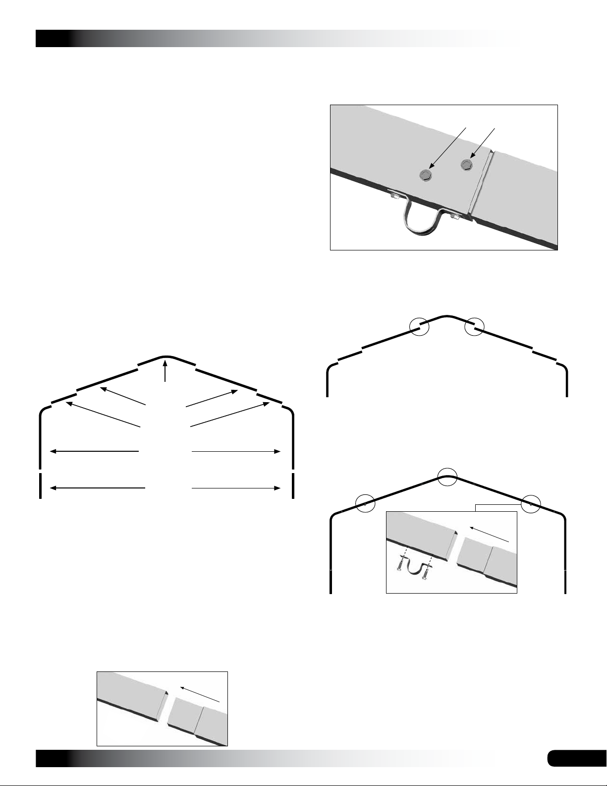
RAFTER ASSEMBLY
Gather parts:
• Rafter pipes: 24CP23P3 and 24CP23P1
CLEARSPAN™ GARAGES
3. Secure each pipe joint using two Tek screws. Verify that
the screws are driven through the outer rafter pipe and
into the swaged section of the inserted rafter pipe.
• Rafter pipes: R23S039 and R23S041
• Rafter pipe 105330 and pipe strap QH1070
• 105090 brace and square tube pipes S20P030
• 105488096 (8' C-channel) and S20P012 (2" x 2")
square tube for cross support and cross support splice
• Rafter connection plates 105087
• Tek screws and magnetic nut setter (3/8'' x 2-9/16")
• 3/8" x 3" bolts with nuts and lock washers
Rafter Assembly Procedure
Each rafter assembly consists of nine (9) rafter tubes: one
(1) curved center pipe (for the top or peak), two (2) bent leg
pipes, four (4) straight pipes between the peak and the bent
leg pipes, and two (2) at the bottom of the leg pipes.
24CP23P3
Tek screws
QH1070
Pipe Strap is
installed later.
ATTENTION: Do not secure the two pipe joints circled
in the diagram below with Tek screws at this time.
These joints are secured when the connection plates
are installed in the steps that follow.
Do not secure these joints using Tek screws
at this time. Doing so will interfere with the
installation of the connection plates.
105330
R23S041
24CP23P1
R23S039
The following steps describe one way to assemble the
rafters. Use the previous diagram for rafter tube placement.
IMPORTANT: To prevent damage to the roof panels, install
the Tek screws so the heads do not touch the roof
panels when these are installed.
1. Select the tubes needed to assemble the rafter and
place these on the ground as shown in the diagram
above.
2. Insert the swaged end of the rafter tubes into the plain
ends of the rafter tubes as needed to assemble the
rafter.
4. Locate three (3) pipe straps (QH1070) and attach
each strap to the rafter assembly on the underside of
the rafter. Consult the diagram below and the Front
Profile diagram in the Quick Start section for pipe strap
locations.
Pipe strap positioned at a rafter joint.
NOTE: The screws used to secure the pipe straps to
the rafter are also used to secure the joint of the two
rafter tubes. When installing the pipe straps, install
screws through one pipe and into the swaged end of
the other pipe at joint.
DO NOT tighten the pipe strap screws at this time.
These are tightened after installing the purlins.
Revision date: 05.20.16
5. Verify all rafter pipe joints, except those noted in Step
3, are secured using Tek screws.
9
Page 10
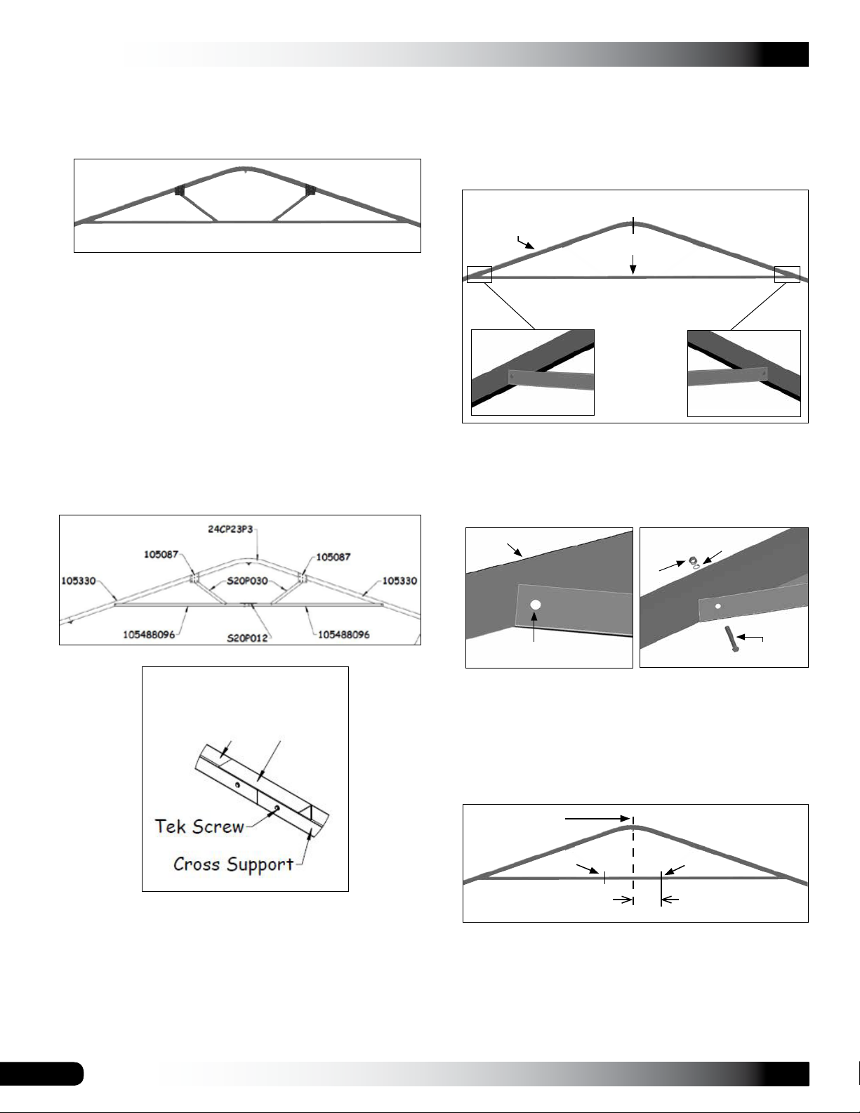
CLEARSPAN™ GARAGES
RAFTER ASSEMBLY (continued)
6. Once rafter tubes for first rafter are assembled and
pipe straps (QH1070) are attached to underside of the
rafter tubes, attach cross support.
9. Position cross support assembly between rafter legs
with channel facing up and toward rafter.
10. Align splice with center of rafter and clamp cross
support to rafter legs. Verify support is level.
Align splice with rafter center.
Cross Support
Required components for one (1) rafter cross support:
• Two (2) S20P030 2" x 2" plain square tubes at 30"
each
• Two (2) 105488096 8' cross support (C-channels)
and one (1) S20P012 Splice Tube
• Four (4) 105087 connection plates with angled top
• Tek screws and 3/8" bolts, nuts, and lock washers
7. Locate two (2) cross support C-channels (105488096)
and a S20P012 splice tube.
8. Connect these using three (3) Tek screws on each
side of splice. Total number of Tek screws for each
splice is six (6).
Rafter
Cross Support
11. Drill a 7/16" hole through the each end of the cross
support and rafter as shown below.
12. Attach cross support to the rafter using 3/8" bolts, lock
washers, and nuts.
Rafter
Cross
Support
Lock Washer
Nut
Cross
Support
NOTE: Install two (2) Tek screws through bottom, two
(2) through front, and two (2) through back of splice for
a total of six (6) screws for each cross support splice.
See also the Front Profile diagram in Quick Start
section near back of this guide.
S20P012
7/16" Drilled Hole
Bolt
NOTE: Position all nuts on the same side of the rafter.
When setting end rafters, position nuts to the inside
of the frame to prevent end panel damage.
13. With support attached at each end, measure 16-1/2"
on each side of cross support splice and mark the
locations for the 2" x 2" diagonal braces.
Center Mark
16-1/2"
14. Drill a 7/16" hole through the cross support at each
location. See the arrows in the above diagram.
10
Revision date: 05.20.16
Page 11
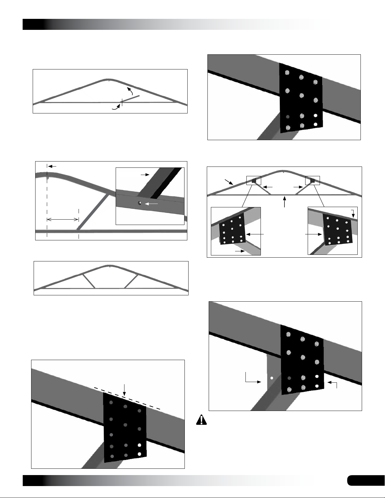
15. Take one S20P030 square tube, set one end inside the
cross support and align the tube with the 7/16" holes.
16. Tilt remaining end of the tube up until it touches the
underside of the rafter.
Drill hole here.
17. While holding the brace in place, use the 7/16" hole in
the cross support as a template and mark and drill the
hole through the S20P030 diagonal brace.
CLEARSPAN™ GARAGES
22. Using Tek screws, the 100441 nut setter, and a drill,
secure plate to rafter and diagonal brace.
NOTE: Some
mounting holes
in bracket will not
be used for this
application.
18. Install the 3/8" bolt, lock washer, and nut to secure the
diagonal brace to cross support.
Center of Rafter
S20P030
16-1/2"
Drill hole for this bolt .
19. With upper end of diagonal brace tight against the
underside of rafter, tighten the 3/8" bolt and nut.
20. Repeat steps to attach the remaining diagonal brace
to the cross support. Assembled rafter bracing to this
point will appear as shown above.
21. Locate one 105087 connection plate, align it with top
edge of rafter and one diagonal brace as shown below.
If screws were installed to secure rafter joint in this
location, remove these to install plate.
Align top of plate with the top edge of
rafter. Do not allow plate to extend
above rafter.
23. Repeat steps to attach another 105087 connection
plate to remaining diagonal brace for rafter assembly.
Rafter
S20P030
Cross Support
Connection Plates
S20P030
Rafter
24. After attaching one plate to each diagonal brace on
one side of the rafter, carefully flip the rafter assembly
over and attach two (2) additional connection plates to
secure braces to after on that side.
NOTE: Some mounting holes
in the bracket will not be used
for this application.
Rafter
Connection Plate
Revision date: 05.20.16
Rafter
Connection
Plate
105087
WARNING: Rafters are heavy. Assistants and lifts
are needed to move assembled rafters.
25. Set the assembled rafter aside and repeat the
procedures to assembly the remaining rafters.
26. After assembling all rafters, assemble the frame.
11
Page 12
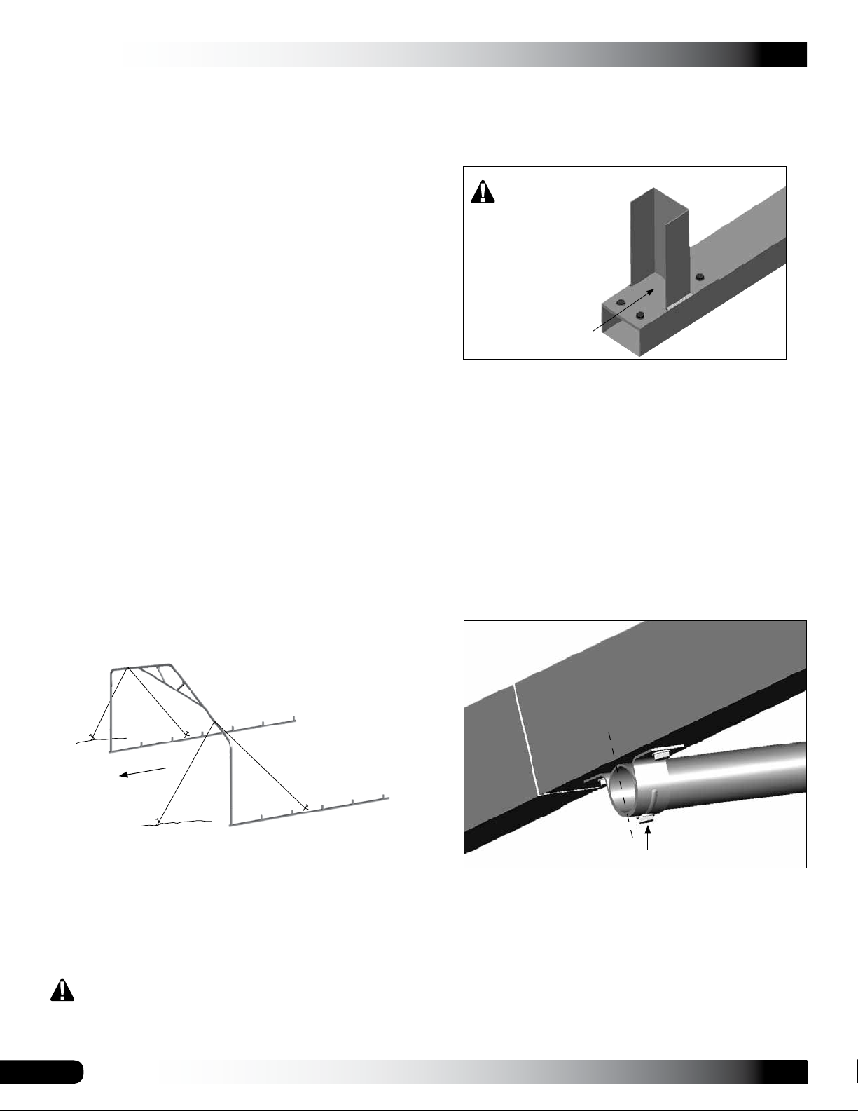
CLEARSPAN™ GARAGES
FRAME ASSEMBLY
The following instructions assume the rafter feet (105088)
are properly spaced on base rails as previously instructed
and that the site is level. A lift is needed to set rafters.
ATTENTION: Level site before continuing. Frame will
not assemble properly without a level site. A level site is
required.
Tools needed: Tape measure and power driver for Tek
screws; lift to set rafters in place.
Gather parts:
• Rafter assemblies and assembled base rails
• 1.315" x 75" swaged pipe (131S075)
• 1.315" x XX" plain pipe (131P0XX)
• Tek screws and 100441 nut setter (3/8'' x 2-9/16")
NOTE: Purlins are part of the assembled frame and run
perpendicular to rafter assemblies. Each purlin consists
of 1.315" x 75" (131S075) swaged pipes (quantity is
determined by shelter length) and one (1) 1.315" x XX"
(131P0XX) plain pipe to finish the run of pipe.
The XX" represents remaining length required to reach end
of shelter. Consult Spec Sheet and Side Profile diagrams in
Quick Start section for part identification.
Assemble Frame
3. Secure rafter leg tubes to each 105088 connector
using two Tek screws. Position screws so they "drill"
into each connector secured to the base rail.
Do not install Tek
screws through the
rafter pipe into this
"open" section of
the 105088 1-way
connector. They will
not secure anything.
4. Carefully position next rafter in place and secure
leg pipes to rafter feet on base rails as previously
described.
5. As the second rafter is steadied, take one section of
75" pipe (131S075), move to the rafter peak, and insert
pipe through pipe strap attached to the underside of the
end rafter.
6. Guide tapered end through pipe strap located in the
same position on the second (or next) rafter.
7. Move to end rafter and align plain end of purlin pipe
flush with (or slightly past) outside edge of pipe strap
as shown below.
1. Carefully lift and stand the first rafter and place leg
pipes on the first set of rafter feet on the base rails.
When setting the end rafter, verify that all bolt heads are
positioned toward the outside of the frame. See arrow.
2. Anchor the first rafter with ropes or other temporary
bracing. Verify that the rafter is plumb (straight).
NOTE: In the diagram (above), ropes (identified by
black lines) are used to temporarily anchor rafter in
place. Frame shown may differ from actual frame.
For this first end rafter, all temporary bracing must
remain in place until other rafters are set and
attached to the first rafter and each other.
Outside face of
the End Rafter
Plain End of Pipe
Tek screw
The purlin and rafter position shown may differ from the
actual position. It is used to show purlin-to-rafter connection.
8. Tighten pipe strap Tek screws and secure pipe to strap
using a Tek screw.
NOTE: To prevent end panel or cover damage if
equipped, do not allow the purlin to extend beyond
the end rafter.
12
Revision date: 05.20.16
Page 13
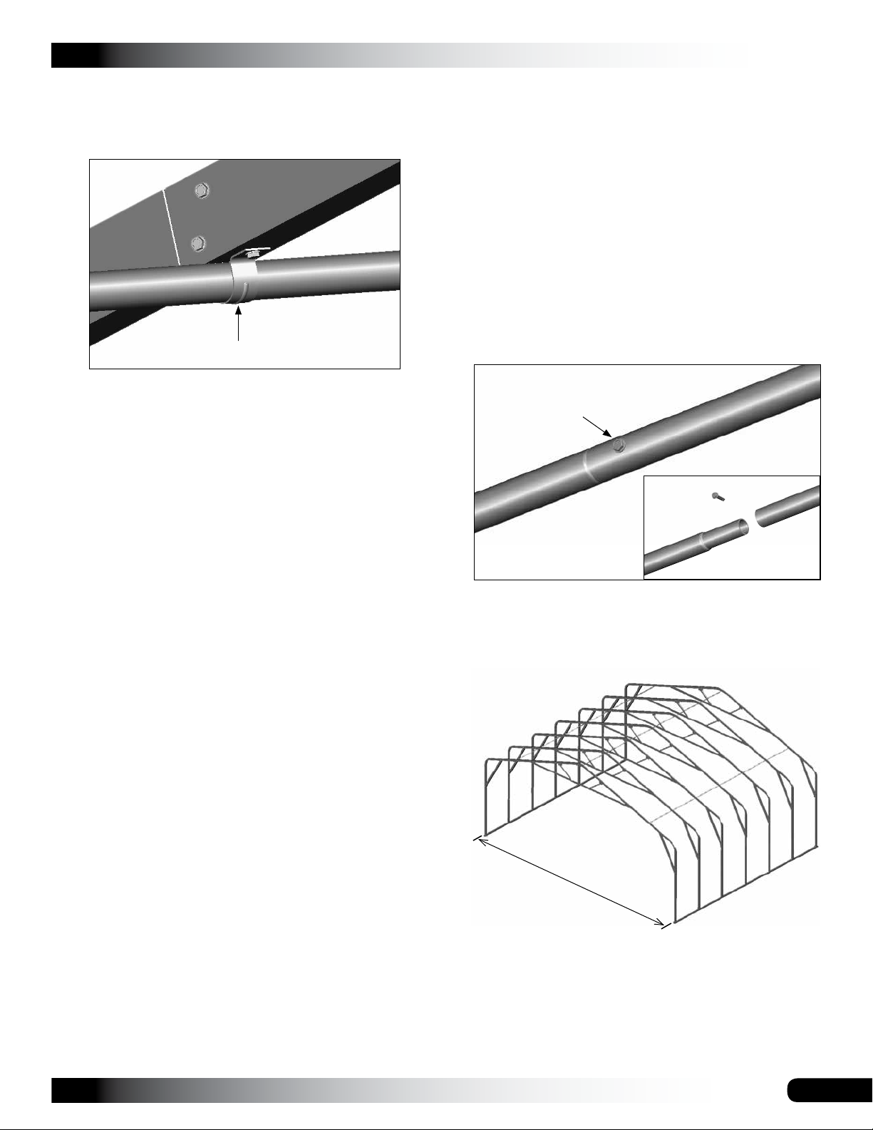
FRAME ASSEMBLY (continued)
CLEARSPAN™ GARAGES
9. Measure between rafter peaks, verify that the on-center
dimension is forty-eight inches (48"), and tighten pipe
strap Tek screws on second rafter.
Pipe Strap
NOTE: Do not secure the purlin pipe to the pipe strap
on the second rafter at this time.
10. Repeat Steps 5-9 to install the first section of purlin
pipe for the remaining purlins for the first two rafters.
11. Choose another rafter assembly and set it in position.
12. Using Tek screws, secure the leg tubes of the
third rafter to the 105088 connectors as previously
described.
ATTENTION: Typically purlin pipes do not need cut.
Verify that you have selected the correct pipe to end
the purlin run before cutting the pipe to length. Consult
the Side Profile diagram for additional details.
Do not allow the purlin to extend beyond the end rafter.
See earlier diagram (Step 7).
18. Once all rafters are set and all purlins are in place
and secured, return to each pipe strap and drive a Tek
screw through the pipe strap and into the purlin. Refer
to the diagram in Step 7 if needed.
19. After securing all purlin pipes to each pipe strap, locate
all purlin pipe joints and secure each of these using a
Tek screw.
Tek screw
Tek screw
13. Take a 75" section of purlin pipe (131S075), slide it
through a pipe strap of the rafter, and place the plain
end of the pipe over the tapered end of the installed
purlin pipe of the first rafters.
14. Verify that the distance between the rafters is 48"
center-to-center. Adjust the rafter forward or backward
as needed to maintain this dimension.
15. Tighten pipe strap Tek screws to secure pipe to rafter.
16. Add purlin pipes to complete purlin runs between
second and third rafters.
17. Repeat the above steps as needed to stand, place, and
secure remaining rafters and purlins to complete the
frame assembly.
Each purlin run is completed using a single plain pipe
that is shorter than the 75" swaged pipes used up to
this point. (These plain pipes do not include a tapered
or swaged end.)
Consult the Side Profile diagram in the Quick Start
section for your building to identify the plain pipe at the
end of each purlin run.
If the last rafter is plumb and the purlin pipe extends
beyond the end of the rafter, cut the last section of
purlin pipe to the required length if needed.
20. Remove the temporary bracing (if needed) and
complete the next steps to square and anchor the
frame.
30'
center-to-center
Frame shown may differ from actual frame. It is used for
illustration only. Diagonal bracing is installed later in this
manual.
Revision date: 05.20.16
13
Page 14
CLEARSPAN™ GARAGES
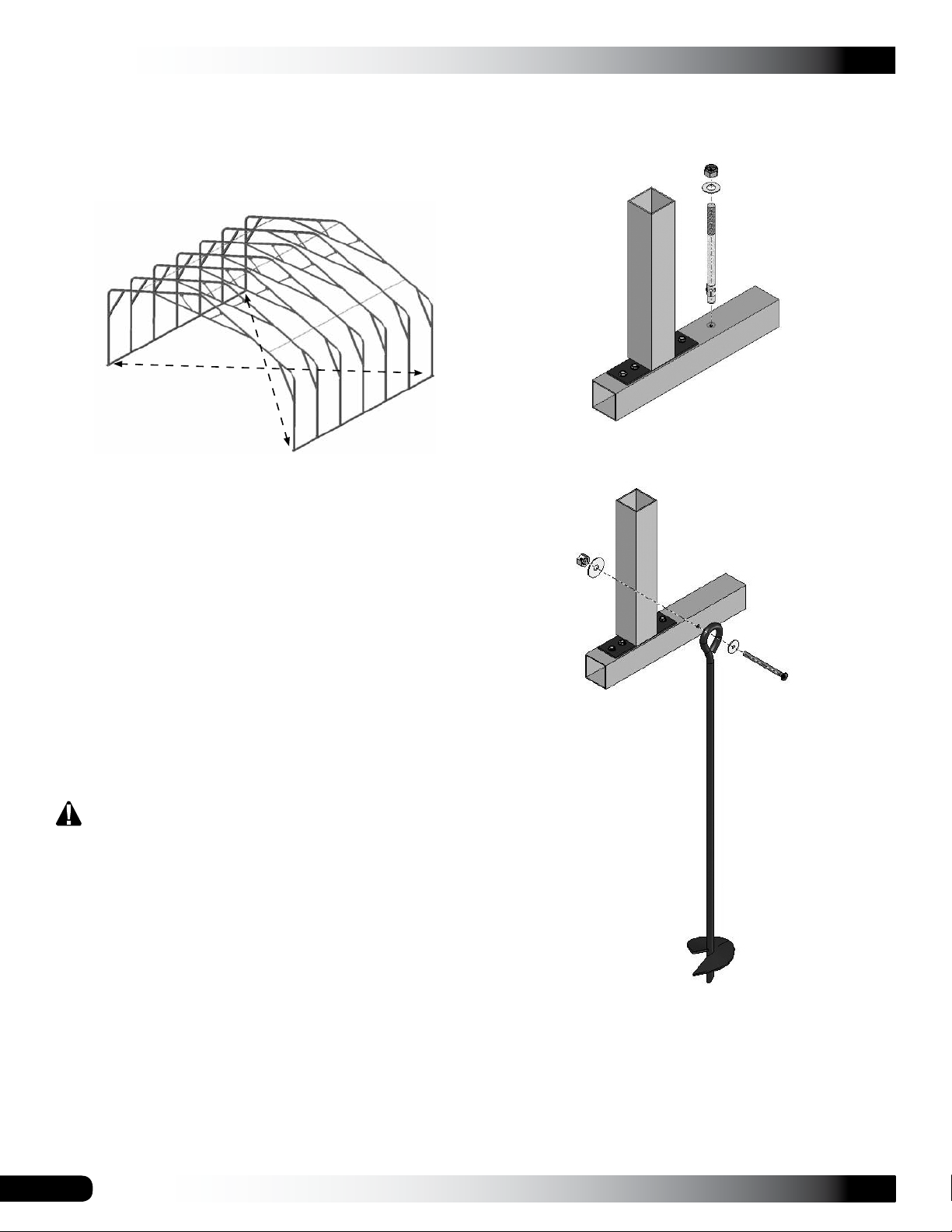
SQUARE THE ASSEMBLED FRAME
Complete these steps:
1. Square the frame by measuring diagonally (cornerto-corner) at the base and verify that the two
measurements are equal. Adjust as needed.
2. Examine the frame and remove any sharp edges from
the frame or reposition screws so they do not come in
contact with the main cover or end panels (if equipped).
The diagrams below illustrate two possible ways to properly
anchor the shelter to the site. Sample frame shown below
may differ from the actual frame.
Anchor System for use on concrete
3. Verify that rafters are plumb and the width of the base
rails are properly spaced at 30' on-center.
4. Verity that all pipe and tube joints are secured with Tek
screws. This includes base rails, rafters, purlins, and all
additional bracing.
5. After the frame is squared, read or reread the MUST
READ document and anchor the frame in place.
ANCHOR THE SHELTER
At this point in the assembly process, anchor the
assembled frame. Once the frame assembly is anchored
properly, continue with these instructions.
WARNING: Securing the base rails to concrete blocks
or wood boards set on the site is not a substitute for
properly anchoring the shelter. You must anchor the
shelter as described in the MUST READ document.
FAILING TO PROPERLY ANCHOR THE SHELTER
WILL RESULT IN DAMAGE TO THE SHELTER AND
MAY CAUSE PERSONAL INJURY.
READ THE MUST READ DOCUMENT TO PROPERLY
ANCHOR THE SHELTER.
Ground Anchor System
Consult the services of a qualified contractor familiar with
anchoring similar structures in the same region (if needed)
to properly anchor the frame.
You must anchor the frame before installing the end panels
and main cover.
14
Install an anchor at each rafter leg along each side of the
frame.
The parts shown in the diagrams regarding anchor systems
are not included with the shelter. Contact Customer Service
at 1.800.245.9881 to purchase additional parts to anchor
the shelter.
Revision date: 05.20.16
Page 15
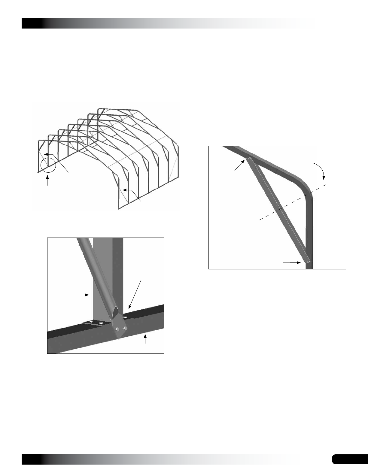
SIDE STRUT INSTALLATION
CLEARSPAN™ GARAGES
INSTALL SHELTER BRACING
Gather parts:
• 8' struts (105119) and Tek screws
Complete these steps to install the four (4) side struts:
1. Locate one (1) eight foot strut and position it between
one end rafter leg and the leg of the first interior rafter
as shown below.
Strut Position
See the diagram
below for details.
Strut Position
2. Align one end of the strut with the center of the interior
rafter leg and secure the strut to the base rail using Tek
screws. See the diagram that follows for clarification.
The diagonal bracing is installed after the frame is squared
and anchored and before installing the end panels and
main cover.
Gather parts:
• Bracing (105090)
• Tek screws
Complete these steps to install the diagonal bracing for the
shelter.
1. Locate one (1) five-foot (5') brace and, beginning at
one end rafter, place it into position as shown below.
Center brace with the
center of rafter bend.
Tek Screws
End rafter showing
the location of the
diagonal brace.
Position all braces
similar to what is
shown in this and
other diagrams.
Attach strut
to base rail.
Interior
Rafter Leg
Base Rail
NOTE: Each strut includes one pre-drilled mounting
bolt hole at each end. Install a second Tek screw
through the strut and into the base rail as shown.
3. Verify that the end rafter is plumb (straight up and
down) and secure the top of the strut to the inside of
the end rafter leg. Do not allow the end of the strut to
extend beyond the edge of the end rafter.
4. Repeat the steps to attach the remaining side struts to
the shelter frame.
5. After securing the four (4) struts, complete the next
procedure to install diagonal bracing.
Tek Screws
NOTE: Before attaching the brace to the rafter leg,
verify that the rafter is plumb (side-to-side and front-toback).
Position the brace so that the center of the brace is
aligned with the center of the rafter bend. Adjust as
needed on the end rafters to avoid contact with the
strut connections.
2. Secure the brace to the rafter using Tek screws as
shown above.
3. Repeat the procedure for the remaining diagonal rafter
braces.
NOTE: To keep the angles of all diagonal bracing
consistent throughout the frame, duplicate the position
of the first diagonal brace.
4. After installing all diagonal bracing, return to each end
rafter and apply a few layers of duct tape or a similar
product over all bolt heads and Tek screw heads. This
will protect the end panel when it is installed.
5. Once the end rafters are prepared for end panel
installation, continue with the following instructions.
Revision date: 05.20.16
15
Page 16
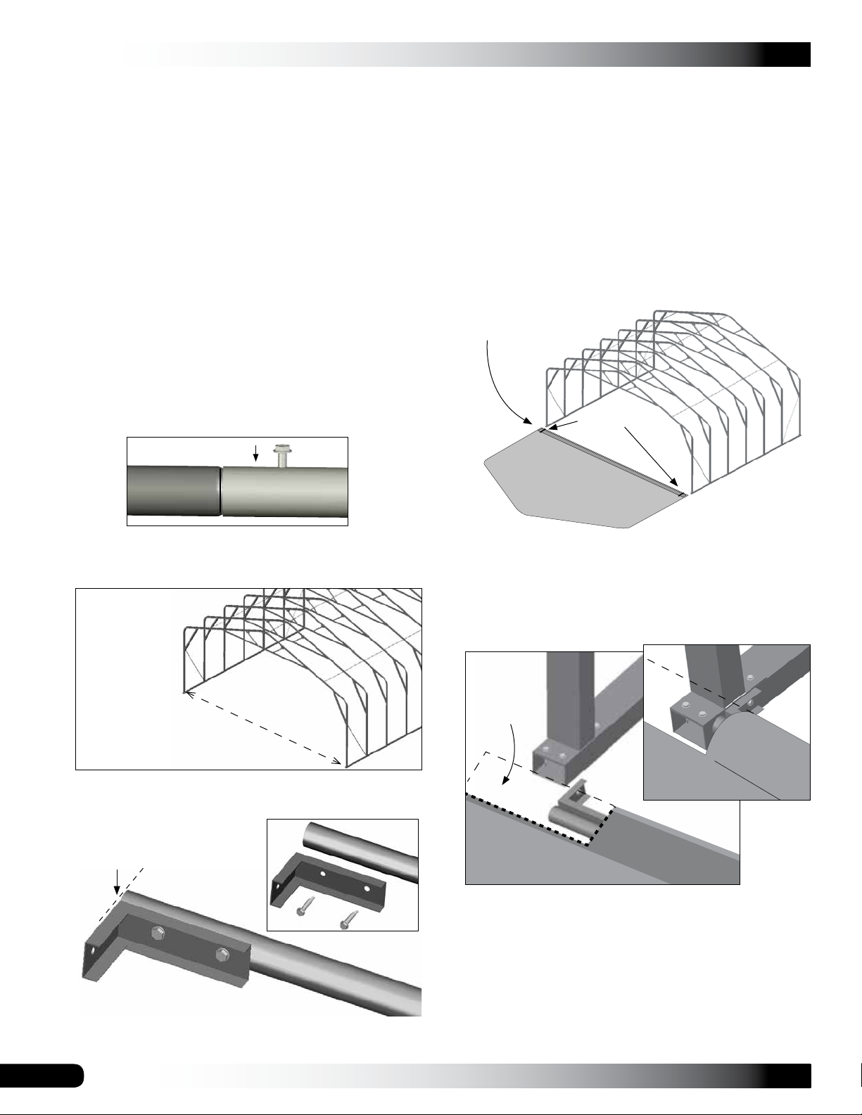
CLEARSPAN™ GARAGES
END CONDUITS ASSEMBLY
INSTALL END PANELS
Gather parts:
• Pipe 1.315'' x 73.5'' plain and 1.315'' x 75'' swaged
• QH1330 Angled brackets and Tek screws
• Duct tape (supplied by customer)
Assembly Procedure
1. Locate the required pipes for each end panel conduit
and insert the swaged end of one pipe into the plain
end of another pipe until the conduit is assembled.
NOTE: The conduit for each end panel for this shelter
consists of the following pipes:
• Four (4) swaged pipe @ 75" (131S075)
• One (1) plain pipe @ 73.5" (131P0735)
2. Secure each pipe joint using a Tek screw and tape the
screw with duct tape to protect the end panel pocket.
After anchoring the shelter, install the end panels. Both end
panels are secured to the end rafters using Tek screws and
neo-bonded washers. The screws and washers are evenly
spaced along the rafter on the inside of the shelter.
The following steps describe one way to install the end
panels. Use FA4482 Tek screws and 102921 washers.
1. Unfold and position the end panel with its bottom
pocket toward the end wall and center the panel with
the end rafter. Verify that nothing will damage the end
panel when spreading it out on the site.
Slide plain end of
conduit into pocket.
Cut pocket
here.
3. Measure between the base rails at the desired end
of the frame and cut the assembled conduit so it fits
between the rails.
Step 3
Measure this distance
(inside-to-inside) and
cut conduit to length.
4. Attach one (1) angled bracket (QH1330) to one end of
each assembled conduit.
Use FA4482 Tek
screws to secure
Flush
bracket to pipe.
NOTE: For zippered panels, position the panel so that
the zippers are centered as desired. Panel shown may
differ from the actual panel.
2. Insert the conduit—the end without the attached
QH1330 bracket—into the end panel pocket.
Remove
this panel
section if
desired.
NOTE: For the zippered end panel, DO NOT install the
conduit through the door-opening sections of the end
panel. Secure bracket using FA4482 Tek screws.
NOTE: Attach the bracket flush with the end of the
conduit as shown above.
16
3. Cut the panel pocket as shown so that the conduit
aligns with the inside edges of the base rail.
Optional: The excess pocket material can be removed
if desired when attaching the panel to the end rafter
legs.
Revision date: 05.20.16
Page 17
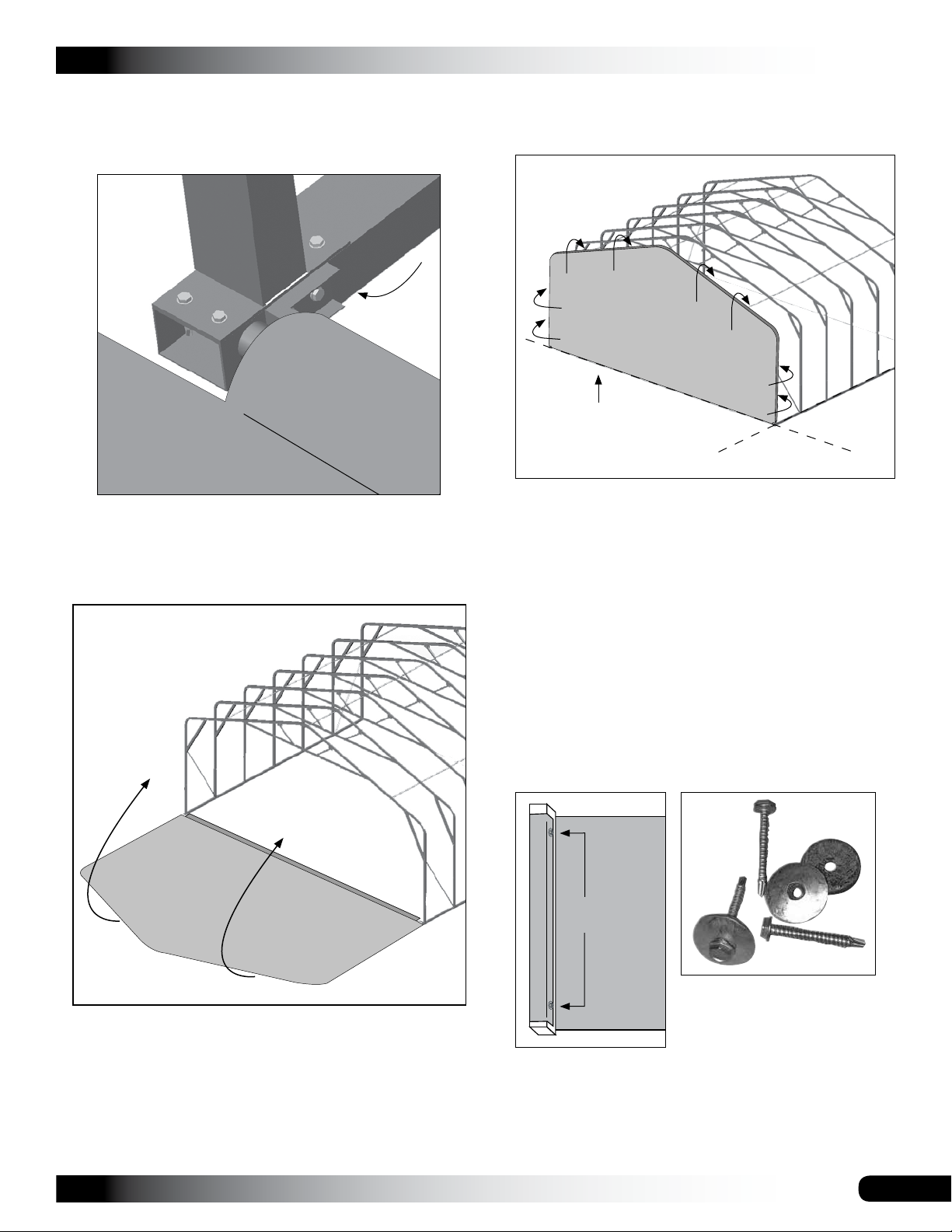
INSTALL END PANELS (CONTINUED)
4. Rotate the angled bracket and attach it to the base
rail as shown in the diagram below. Use FA4482 Tek
screws to secure bracket to base rail.
CLEARSPAN™ GARAGES
7. Pull the end panel up and over the top of the end rafter
and hold it in position.
Keep the lower edge
of the end panel on the
ground while stretching
the end panel.
5. Move to the other end of the end panel conduit, slide
the end panel just enough to attach another QH1330
angled bracket to the conduit and secure the remaining
end of the conduit to the base rail as previously
described.
NOTE: Use additional help to pull the end panel into
position over the entire rafter. It may be helpful to have
someone stand on the conduit near the middle to keep
it on the ground when stretching and attaching the end
panel. Do not over-stretch the end panel.
8. Move to the lower section of the rafter leg and end
panel on each side of the rafter, fold the end panel
material around the rafter tube, and secure it with
Tek screws and washers on the inside of the rafter
approximately 12" up from the conduit.
Attaching the panel in this manner keeps the lower
section of the end panel in place as the panel is
stretched and secured to the rafter.
Inside View
Tek screw
and washer
6. Once the conduit of the end panel is secured between
the base rails, locate the FA4482 Tek screws and
102921 neo-bonded washers that are used to attach
the end panel to the end rafter.
Revision date: 05.20.16
Space the FA4482 screws
and 102921 washers evenly
at 12"-16" when securing the
end panel. Actual screw length
may differ from what is shown.
NOTE: Install the screws on the backside or inside
surface of the rafter to prevent damage to the main
cover when it is installed.
17
Page 18
CLEARSPAN™ GARAGES
INSTALL END PANELS (CONTINUED)
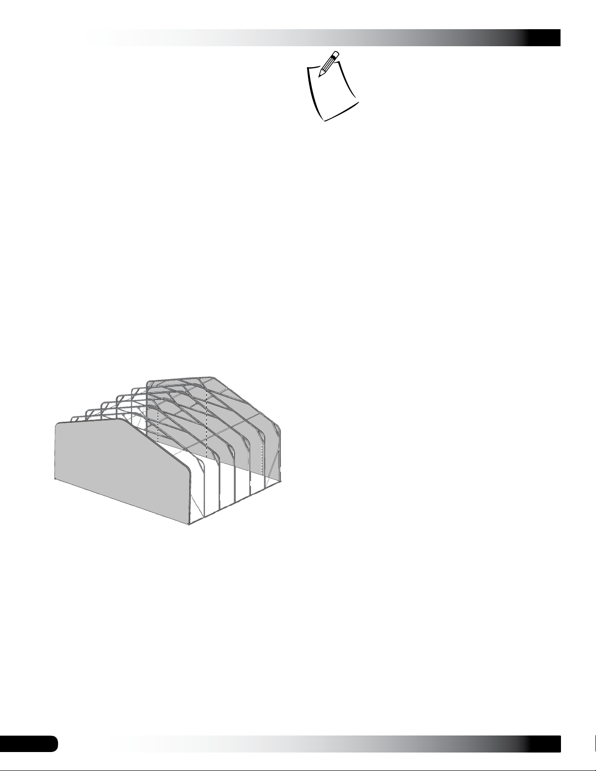
9. After securing the lower section of the end panel to
the end rafter, stretch the panel over the top to remove
wrinkles, and secure it in place as previously described.
Use additional assistants to properly and evenly stretch
the end panel during installation.
Verify that the conduit inside the panel pocket remains
on the ground as the end panel is stretched over and
around the end rafter.
Evenly space the FA4482 screws and 102921 washers
(12"-16") along the rafter and pull the end panel tight
as the screws are installed. To prevent damage to the
main cover, do not install the Tek screws in a position
that allows the heads of the screws to contact the main
cover when it is installed.
10. Continue attaching the end panel by working evenly
down both sides of the rafter toward the base rails.
NOTE: If necessary, remove the Tek screws at the
bottom of each rafter leg to work wrinkles out of the
end panel and reinstall the Tek screws.
11. After installing the first end panel, repeat the steps to
attach the remaining end panel.
Space below is reserved for customer notes.
FRONT
NOTE: The excess end panel material can be removed
or folded and attached to the rafter as described earlier.
If the excess is removed, allow at least six inches (6")
to remain beyond the Tek screws.
In the future, if the panel is removed for any reason, the
extra material is used to pull the panel tight.
12. After installing both end panels, install ratchets and the
main cover.
18
Revision date: 05.20.16
Page 19
PREPARE MAIN COVER
CLEARSPAN™ GARAGES
Gather parts:
• Ratchets (1"), main cover, and Tek screws
• 1.315" x 75" swaged pipe (131S075)
• 1.315" x XX" plain pipe (131P0XX); See Side
Profile diagrams in the Quick Start section for pipe
identification for your building.
Assembly Procedure
NOTE: When handling the main cover and setting it in
position, do not pull on the end straps. They will pull out of
the cover.
WARNING: To prevent damage to the cover and to
prevent serious personal injury, DO NOT attempt to
install the main cover on windy days.
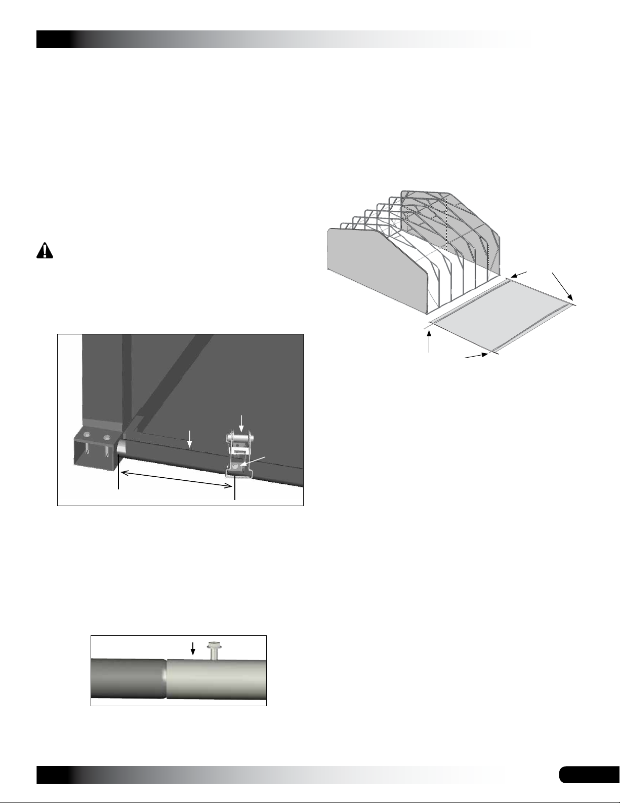
1. Fasten a ratchet to the end conduit using a Tek screw
as shown below. The ratchet should be about 6" in from
the end of the conduit.
End Panel
4. After assembling the cover conduits, take the main
cover and unfold it on a clean, smooth surface near the
frame.
NOTE: Unfold the main cover with the inside surface
facing up.
5. Locate the main cover ends with strapping and align
with the front and back of the shelter.
Front with zippered
end panel.
Cover
Ends with
Strapping
Cover Conduits
Ratchet
End Conduit
FA4482
Tek Screw
6"
2. Repeat Step 1 at all remaining corners.
3. Assemble two main cover conduits. Consult the Side
Profile diagrams for pipe identification for your building.
a. Locate all sections of pipe needed and insert
the swaged end of each pipe into the plain end
of another pipe until the conduit is assembled.
b. Secure each pipe joint with a Tek screw and
tape the screw and joint with duct tape.
6. Insert the cover conduits into the pockets of the main
cover.
NOTE: Shelter shown above may be of a different
length than actual shelter. Do not insert a cover conduit
into any pocket that includes a pre-installed strap.
7. Continue by attaching the main cover ratchets and the
main cover to the frame.
ATTENTION: Cover conduits are inserted into the
pockets sealed into the main cover. The conduits are
used to tighten and secure the main cover.
Revision date: 05.20.16
19
Page 20
CLEARSPAN™ GARAGES
ATTACH MAIN COVER
Gather parts:
• Main cover (with conduits already inserted)
• Ropes long enough to reach over the frame (provided
by customer)
• Ratchets (1"), Tek screws, and 103620B straps
• Box cutter or utility knife
WARNING: To prevent damage to the cover and to
prevent serious personal injury, DO NOT attempt to
install the main cover on windy days.
Assembly Procedure
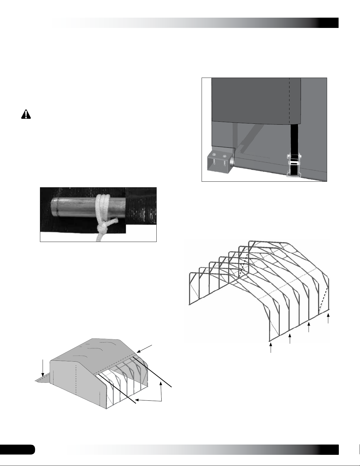
1. To pull the cover over the frame, attach ropes to both
ends of the cover conduit. Wrap the rope around the
conduit a few times to prevent it from slipping off.
4. Once the main cover is pulled into position, center
the cover on the frame and loosely secure the ends
of the cover to the ratchets attached to the end panel
conduits.
Main Cover Bonnet
End
Panel
ATTENTION: Do not tighten the straps at this time. Use
ropes to temporarily secure the sides of the cover to
the frame if needed.
NOTE: Depending on the length of the cover it may
be necessary to attach additional ropes to the cover
conduit between the end ropes by cutting a small
opening in the cover pocket and tying the rope around
the conduit. DO NOT cut through the main cover. Cut
through the conduit pocket only.
2. With all ropes attached to the cover conduit, lift the
conduit and carry the cover toward the base of the
frame.
3. Toss the ropes over the frame and pull the cover into
position. One person is required at each rope.
Cover
Conduit
Front
Cover Conduit
Ropes
5. Divide the remaining number of ratchets in half and
place the ratchets on the ground next to the rafter
where they will be attached.
End panel and cover not shown.
Diagram may show a different
shelter length.
NOTE: Space ratchets evenly along each side of
the shelter and directly across from each other on
the same rafter assembly. Consult the Side Profile
diagrams in the Quick Start section for ratchet location
details for your building.
Secure ratchets using the FA4482 Tek screws.
20
Diagram may show a different shelter length.
Revision date: 05.20.16
Page 21
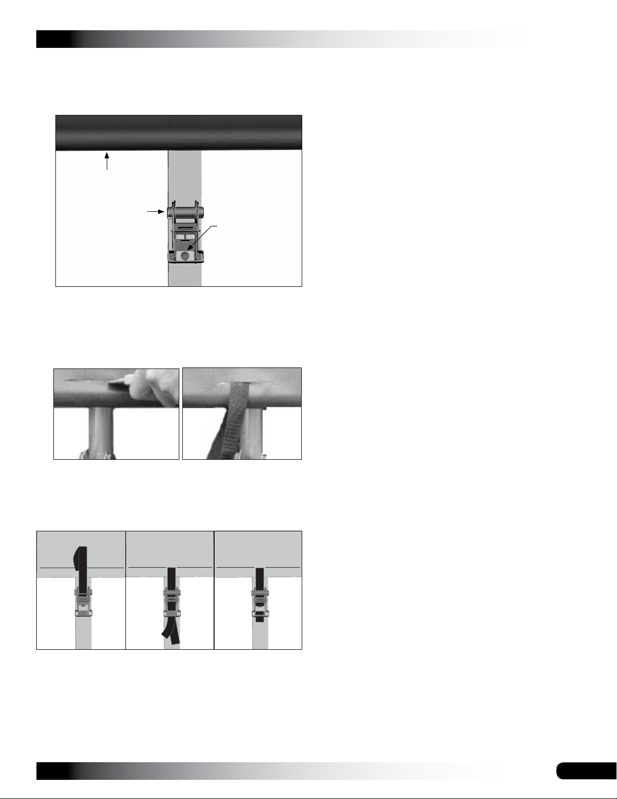
ATTACH MAIN COVER (CONTINUED)
CLEARSPAN™ GARAGES
6. Lift the cover skirt and using the main cover conduit
and strap length as guides, attach the ratchets to the
rafters. Fasten ratchets to rafters using Tek screws.
Main Cover Conduit
Ratchet
FA4482
Tek Screw
NOTE: Ratchets may be fastened to either the outside
(shown) or inside (not shown) of the shelter frame.
7. Carefully lift the cover skirt and cut a slit in the cover
conduit pocket at the rafter position. Insert a section of
strap through the slit and around the cover conduit.
10. Using additional help (if needed) tighten the main
cover beginning with the ratchets along the sides of the
shelter frame.
11. After the side ratchets are tightened, return to the end
ratchets and tighten the bonnet straps of the main
cover.
NOTE: To reposition the cover, loosen all ratchets and
then retighten the ratchets.
12. Fold the skirt of main cover down and over the ratchets
to complete the installation of the main cover.
Optional Step: If desired, take the remaining Tek
screws and washers and from the outside secure the
main cover skirt to the base rail along each side of
the frame. Evenly space the Tek screws as previously
described..
CARE AND MAINTENANCE
Proper care and maintenance of your garage is important.
Check the following items periodically to properly maintain
your garage:
NOTE: DO NOT cut through the main cover. Cut
through the conduit pocket only.
8. Thread the strap ends into the ratchet and slightly
tighten.
NOTE: It may be necessary to remove excess strap if it
binds up in the ratchet.
9. Repeat the steps for the remaining ratchets.
• Frequently inspect building and all components.
• Replace damaged or worn parts promptly.
• Regularly check main cover and end panels to see they
remain tight and in proper repair.
• Check connections and all fasteners to verify they
remain tight.
• Verify that the anchor system is in good repair and all
connections and fasteners are tight.
• Do not climb or stand on the shelter at anytime.
• Remove debris and objects that accumulate on shelter.
Use tools that will not damage main cover or end
panels when removing debris.
• Remove snow to prevent excess accumulation. Use
tools that will not damage main cover when removing
snow. NEVER ALLOW SNOW TO ACCUMULATE ON
THE COVER.
• Check shelter contents to verify that nothing is touching
main cover or end panels that could cause damage.
• If shelter is disassembled and moved, inspect all parts
and fasteners before use and reassembly.
• For replacement or missing parts, call 1.800.245.9881
for assistance.
Revision date: 05.20.16
NOTE: With the exception of Truss Arch buildings,
ClearSpan™ shelters and greenhouses do not have any
tested loading criteria.
21
Page 22
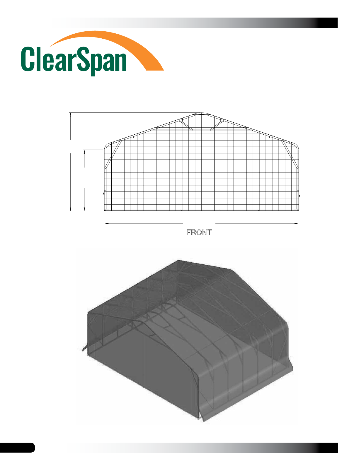
CLEARSPAN™ GARAGES
15'3 3/4"
QUICK START GUIDE
30' Wide Garage
Height
9'6 1/8"
Sidewall
Height
Width30'0"
FRONT
Grid Represents 12" Squares
22
Shelter shown above may be of a different length than actual shelter.
Revision date: 05.20.16
Page 23
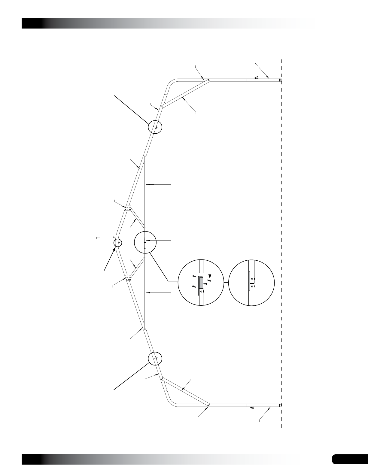
CLEARSPAN™ GARAGES
QH1070 Pipe
Strap Location
105330
105087
R23S041
24CP23P1
105090
R23S039
S20P030
24CP23P3
FRONT PROFILE
QH1070 Pipe
Strap Location
105087
105330
QH1070 Pipe
Strap Location
R23S041
Tek Screws (6)
Ground Level
S20P012105488096 105488096
105090
Revision date: 05.20.16
24CP23P1
R23S039
23
Page 24
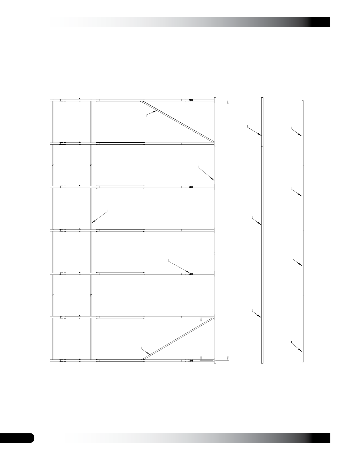
CLEARSPAN™ GARAGES
Purlin
105119
Ratchet:
QH1061
Base
Rail
R23P054
105331105331
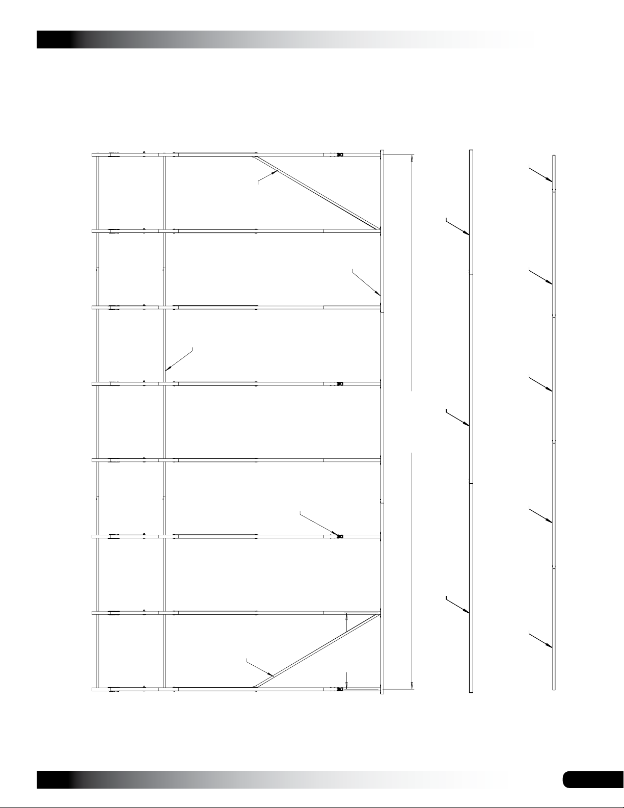
24'0" Length
131P0735
131S075
Purlin Assembly
Base Rail Assembly
131S075
24
SIDE PROFILE - 107771
105119
4'0"
Rafter
Spacing
131S075
Revision date: 05.20.16
Page 25
CLEARSPAN™ GARAGES
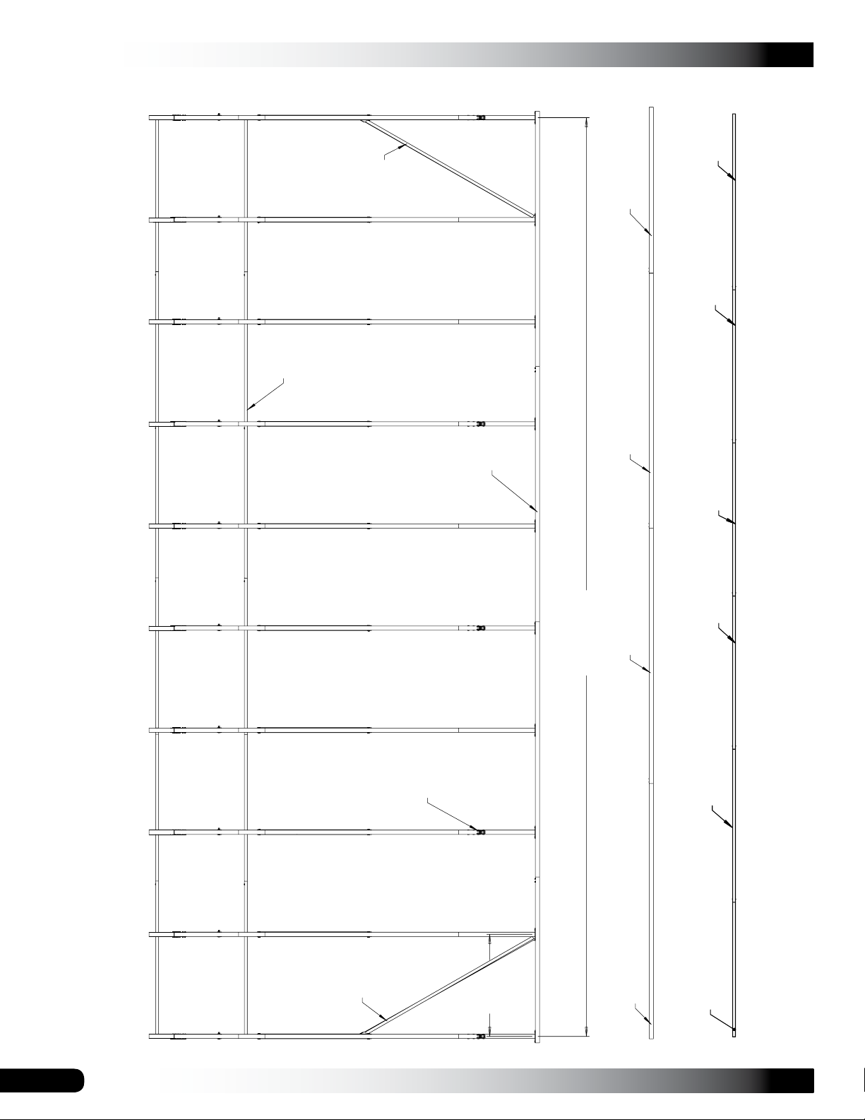
131P0495
105119
Base
Rail
Purlin
28'0" Width
Ratchet:
QH1061
R23P102
105331
Base Rail Assembly
131S075 131S075 131S075
Purlin Assembly
SIDE PROFILE - 107772
Revision date: 05.20.16
105119
4'0"
Rafter
Spacing
105331
131S075
25
Page 26
CLEARSPAN™ GARAGES
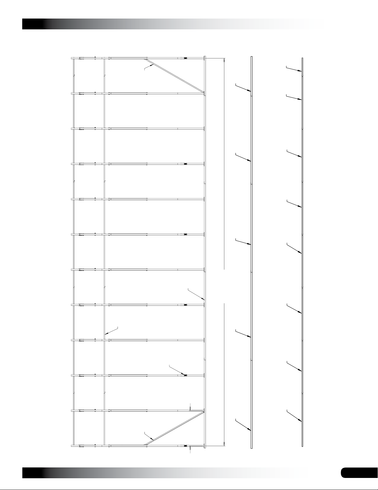
Purlin
105119
Base
Rail
131P0735
131S075
SIDE PROFILE - 107773
Ratchet:
QH1061
105119
4'0"
Rafter
Spacing
105331 105331 R23P078
36'0" Length
105331
131S075 131S075
Purlin Assembly
Base Rail Assembly
131S075
131S075
26
Revision date: 05.20.16
Page 27
CLEARSPAN™ GARAGES
131P0255
105119
131S075
Base Rail Assembly
Purlin Assembly
Base
Rail
Purlin
SIDE PROFILE - 107774
Ratchet:
QH1061
105119
4'0"
Rafter
Spacing
44'0" Length
131S075 131S075 131S075 131S075 131S075 131S075
105331 105331 105331 105331 R23P054
Revision date: 05.20.16
27
Page 28
CLEARSPAN™ GARAGES
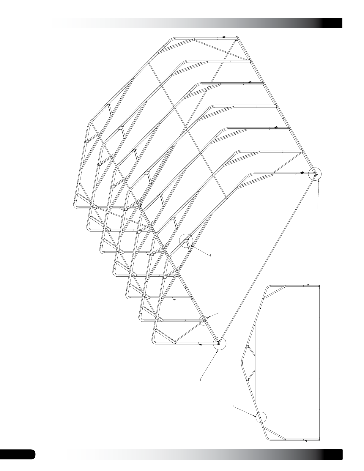
CONNECTIONS
Rafter Plate
Connection
View 1
Base Rail-Strut
Base Rail-Purlin
Connection
View 4
Connection
View 5
Rafter-Purlin
Connection
View 3
Base Rail-Rafter
Connection
View 2
28
Revision date: 05.20.16
Page 29
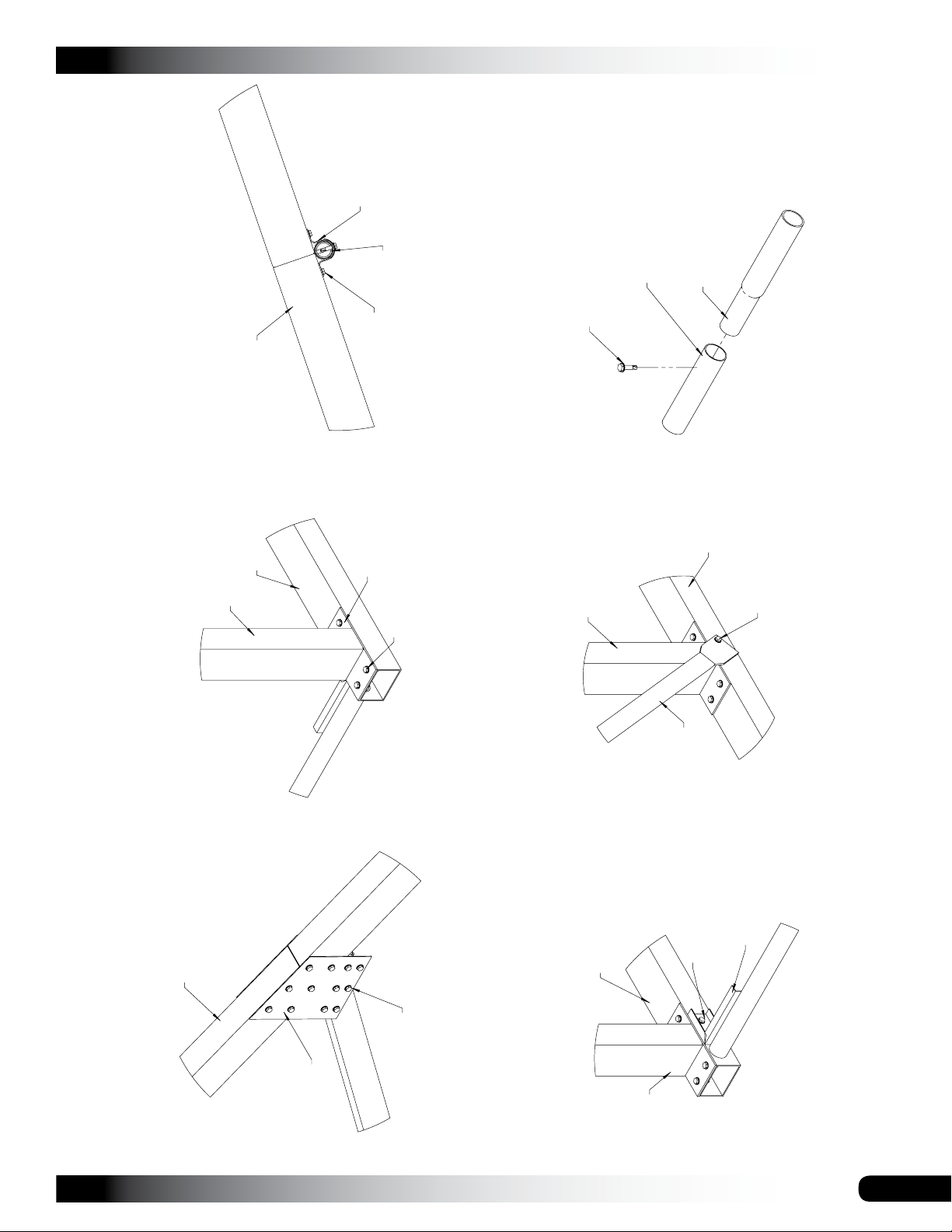
QH1070
Pipe Strap
Purlin
View 3
Connection
Rafter-Purlin
PLAIN END OF
CONDUIT
SELF-TAPPING
TEK SCREW
CLEARSPAN™ GARAGES
SWAGED END
OF CONDUIT
CONDUIT
ASSEMBLY
Rafter
Base Rail
Rafter
Tek Screw
105088
Tek Screw
View 2
Connection
Base Rail-Rafter
Rafter
EXPLODED VIEW
Base Rail
Tek Screw
View 5
Connection
Base Rail-Strut
105119
CONNECTION - DETAILS
Rafter
Revision date: 05.20.16
Rafter
Connection
plate:
105087
Tek Screw
Rafter Plate
QH1330
Base Rail
View 1
Connection
Tek Screw
View 4
Connection
Base Rail-Purlin
Rafter
29
 Loading...