

ClearSound CL2L User Manual

This product may be purchased from Connevans Limited
secure online store at www.DeafEquipment.co.uk
DeafEquipment.co.uk
Offering you choice
Helping you choose
Connevans.info
Solutions to improve the quality of life
Telephone ringer amplifier with flasher and
Indicateur d’appel téléphonique avec flash
Telefonklingelverstärker mit
CL2L
door bell
et sonnette
Blitz und Türklingel
English Page 2
Français Page 15
Deutsch Page 28

CAUTION: The switch for Ringer ALARM
selection must never be set during ringing/
flashing mode but always when CL2 is silent
mode ( No incoming call ringing).
ATTENTION: Le commutateur de configuration
du mode Alarme ne doit jamais être changé
lorsque le CL2 envoie sa sonnerie (ou flash
lumineux ) mais uniquement durant le mode
repos.
WARNUNG: Bitte die Taste für die Auswahl
des Klingeltons niemals während des Läutens
bzw. Blitz-Signals betätigen, sondern nur im
Ruhe-Modus ( kein eingehender Anruf ).
1
DESCRIPTION
g
(*)
p
)
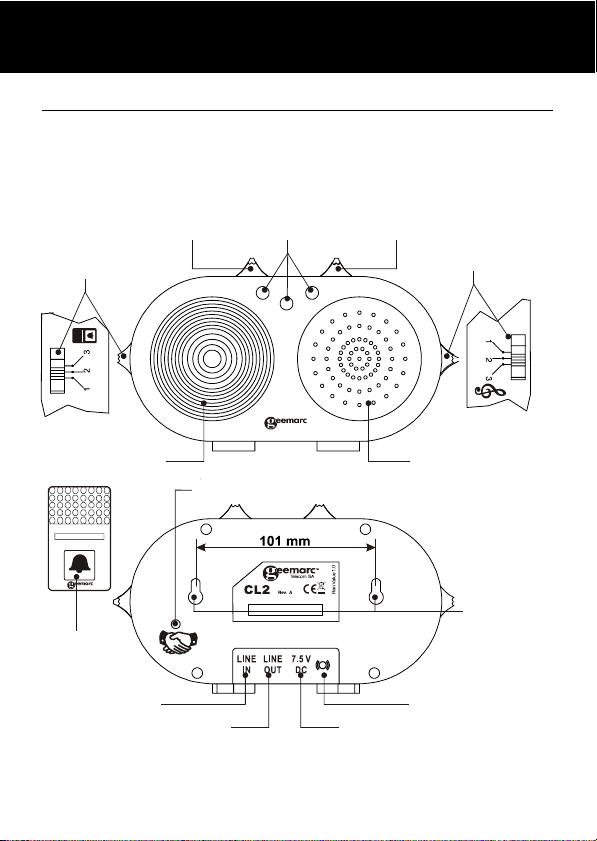
1. DESCRIPTION
The CL2 will alert you to both doorbell and telephone. It
has adjustable volume and different tone settings for
doorbell and telephone.
Doorbell Tone
control
Strobe flasher
BELL PUSH
Bell push
button
Telephone line
cord socket
(*) Classified TNV-3 according to EN60950 standard.
4 ringer
settings
Pairing/Test Button
Modular jack for
hone line cord (*
tele
Door bell
LED
Volume
control
Mains power lead socket (*)
FRONT VIEW
Phone ringer
amplifier tone
control
Loud sound
alarm
REAR VIEW
Wall mountin
holes
Shaker socket (*)
2
INSTALLATION
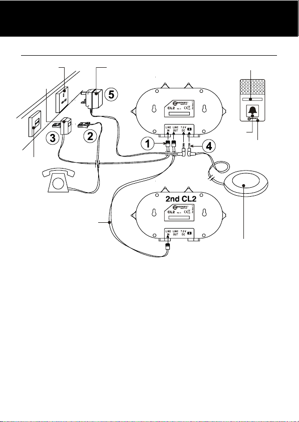
2. INSTALLATION
230V
Double plug
Wall socket
Telephone
Option :
Special cable
two CL2s
1 - Connect the CL2 line cord in CL2 “Line IN”.
2 - Connect your Telephone in the double plug of the line
cord.
3 - Connect the double plug in the Telephone wall socket.
4 - If necessary connect the required shaker
(SHAKCL_BLK only) to the shaker plug input.
5 - Connect the mains adaptor line cord in CL2 12V DC
input.
6 - Connect the mains adaptor in the 230V wall socket.
(*)
to link
AC/DC
Screw wall mount
Door Bell
Button
Door Bell
Option : Shaker
(ref.: SHAKCL_BLK only)
3

INSTALLATION
(*) Classified "hazardous voltage" according to EN60950
standard.
Electrical connection: The apparatus is designed to
operate from a 230V 50Hz supply only. (Classified as
'hazardous voltage" according to EN60950 standard).
The apparatus does not incorporate an integral power
on/off switch. To disconnect the power, either switch off
supply at the mains power socket or unplug the AC
adaptor. When installing the apparatus, ensure that the
mains power socket is readily accessible.
Telephone connection: Voltages present on the
telecommunication network are classified TNV-3
(Telecommunication Network Voltage) according to the
EN60950 standard.
4
BELL PUSH WALL MOUNTING
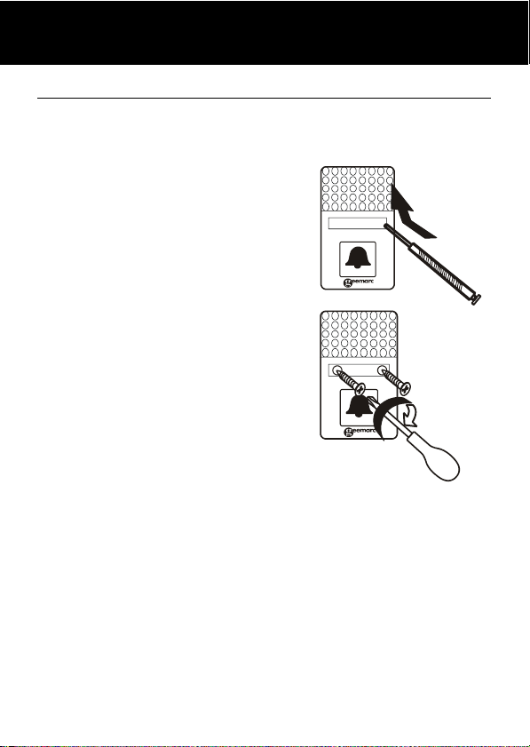
3.1. BELL PUSH – WALL MOUNTING
The wire free bell push is mounted by the front door. It
has a range of 20-60 metres depending on the structure
of the building (see note).
Test the system before mounting
on the wall – plug in the CL2 and
press the bell push button to
check that the CL2 rings.
To mount the bell push, open
the access cover in the middle of
the bell push with a needle or
small screwdriver.
Decide where to position the bell
push and use the wall mount
template, shown below, to mark
the holes on the wall or door
surround and drill holes if
necessary.
Align with prepared marks or screwholes, insert and
tighten screws and replace access cover.
Bell push is now ready for use.
Note: Do not place the bell push onto a metallic base or
near electric equipment (such as TV, Radio, computer,
washing machine...). The CL2 will work within a range of
60m in an environment where there are no obstacles
and 20m in an environment which contains a wall or
metallic structure.
5
WALL MOUNTING BELL PUSH
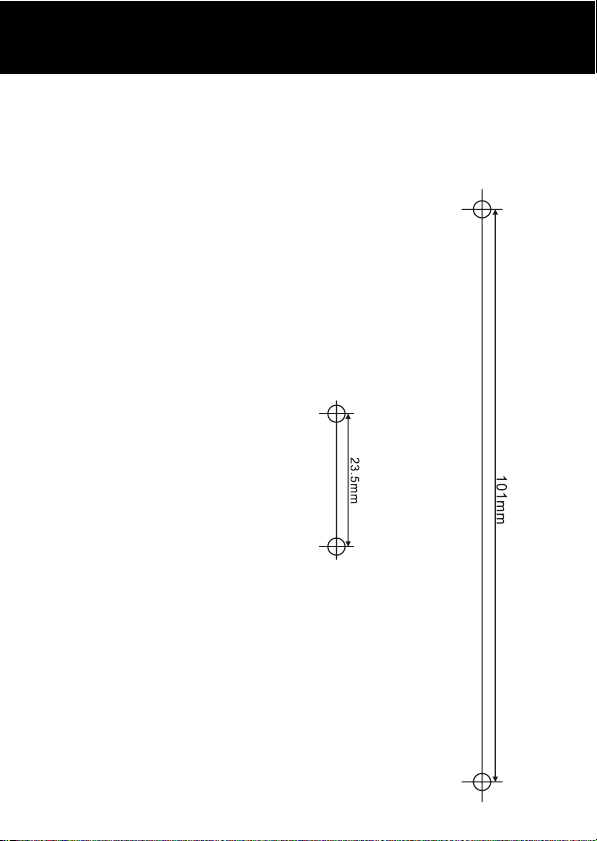
WALL MOUNTING TEMPLATES
To wall mount the bell push or the CL2, use these
templates to mark the screw hole centres. We
recommend the use of a spirit level to ensure the holes
are level.
Bell push template
CL2 template
6
BELL PUSH CHANGE THE BATTERY
3.2. CHANGE THE BATTERY
The door bell is supplied with a 23A 12V battery. The
CL2 is supplied ready to use, it is not necessary to open
the bell push when you first install the CL2.
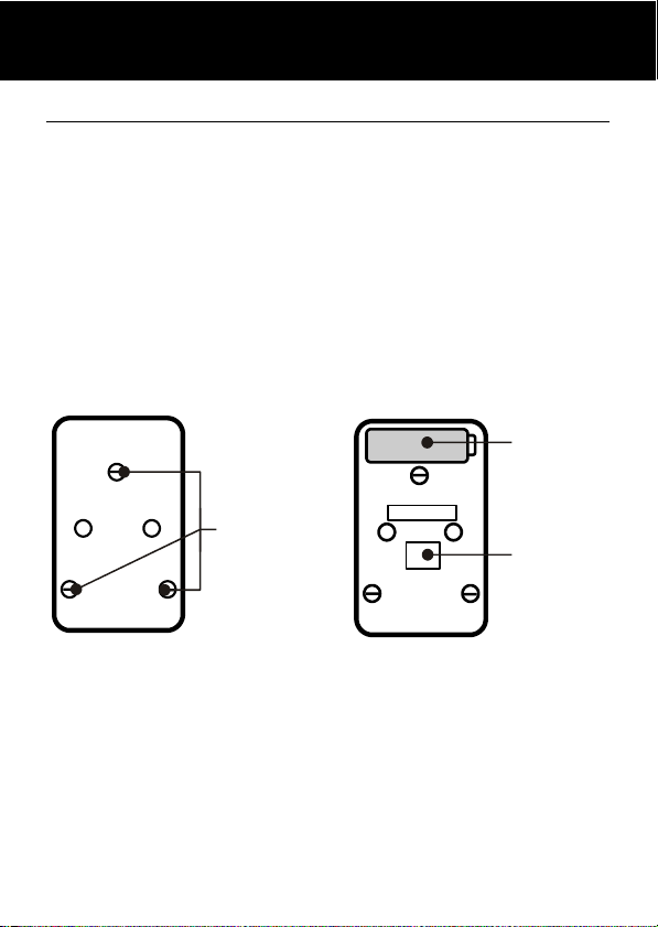
To replace the battery, open the access cover and
unscrew the door bell from the wall, unscrew the three
screws located on the base and open the box to get
access to the battery compartment. Replace the battery,
replace back and remount.
Back of Bell Push Inside Bell Push
Battery
Note: Do not use a rechargeable battery. Do not put the
used battery into the household rubbish, pay attention to
battery regulations regarding battery disposal.
Unscrew to
open
Switches for
LED colour
7
CL2 SETTINGS
4.1. CL2 SETTINGS
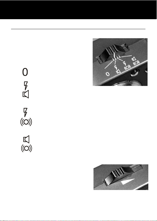
ALARM MODE SETTING
For incoming calls – choose
which alarm mode you want by
moving the alarm mode switch
to one of the following positions:
No alarm selected
Doorbell/ringer
amplifier and strobe
flasher
Doorbell, strobe
flasher and shaker
(if connected)
Doorbell/ringer amplifier and shaker
(if connected)
Flasher:
Bell push – 3-4 flashes
Telephone – flashes as
long as phone rings
VOLUME CONTROL
For doorbell and ringer amplifier:
Use the slider control to adjust
the volume of the sound alarm
of the CL2.
8
SETTINGS CL2
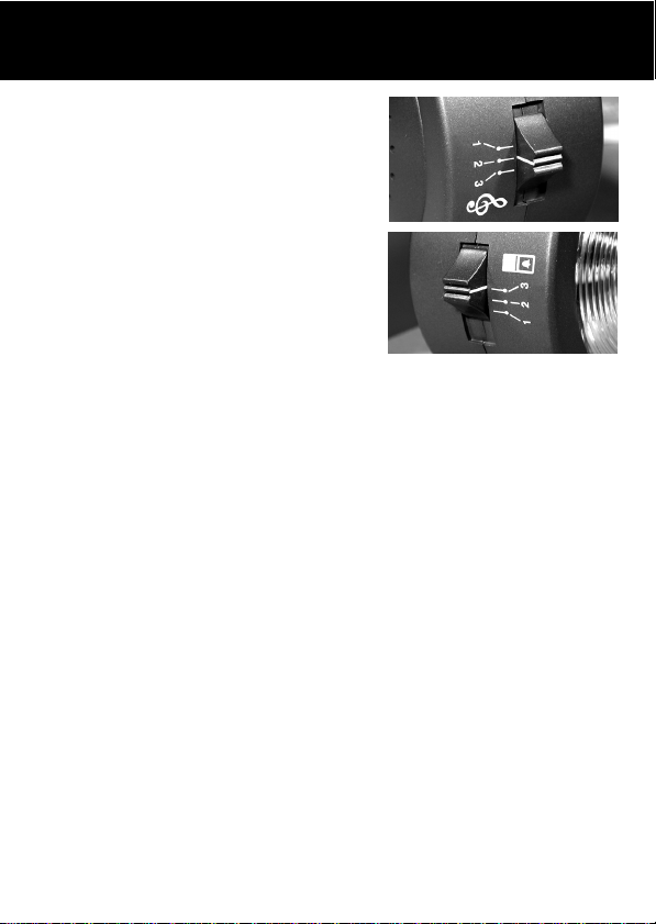
RING TONE CONTROL
The three position switch allows
you to set the tone of the CL2
ringer when the telephone rings.
DOOR BELL TONE CONTROL
This three position switch allows
you to set a different tone when
the door bell rings.
OPTIONAL ACCESSORIES:
Extra bell push – to cover a second door, such as a
kitchen door.
Shaker – the Geemarc shaker unit (CLA2) can be
tucked under your pillow or at the side of your chair to
vibrate when the doorbell or telephone rings. Particularly
useful for hearing aid wearers, when they are not
wearing their hearing aids at night.
Wrist watch alarm – can be worn by someone in the
house who is bedbound and may need to call for help.
To purchase these items, contact your dealer. In case of
difficulty, visit the Geemarc website on:
www.geemarc.com
9

PAIRING SETTINGS
4.2. The Pairing Procedure
( Note : Factory default setting : paired. )
1. Press and hold the
seconds to enter pairing mode, at the same time, the
unit makes a beep sound.
2. The 1st LED lights, to pair the BELL PUSH, press and
hold the
push button at the same time, the 1st LED flashes,
after paired, the 1st LED lights and stop flashing,
beeps to confirm.
3. If user wants to pair the 2nd or 3rd BELL PUSH, when
the 1st LED lights, press the
button within 2 seconds, the 1st LED goes off and
then the 2nd LED lights. User is able to pair the 2nd
BELL PUSH, repeat the same procedure for the 3rd.
4. Repeat the above, all 3 LEDS flashing together for the
4th BELL PUSH pairing, the BELL TONE is not
adjustable for the 4th BELL PUSH.
5. If paired more BELL PUSH on same LED, only the
last one kept.
(Pairing/Test) button and then Bell
(Pairing/Test) button for 2
(Pairing/Test)
10

SETTINGS PAIRING
4.3. Un- Register The Pairing
1. Press and hold the Pairing/Test button for 5 seconds
to enter un-register mode, 3 LED light together.
2. If user wants to un-register the 1st BELL PUSH,
press the Pairing/Test button within 2 seconds, the 1st
LED will be flashing (the other 2 LED light), means
user is now un-registering the 1st BELL PUSH, press
the Pairing/Test button until the 1st LED goes off,
beeps to confirm. The 1st remote is now un-registered.
3. If user wants to keep the 1st BELL PUSH but un-
register the 2nd or 3rd BELL PUSH, when the 1st LED
flashes, press the Pairing/Test button within 2 seconds,
the 2nd LED flashes (other 2 LED light), to select
which BELL PUSH to be un-registered.
Note :
1. To check whether the unit works normally, you can
press the
sound alarm and flash.
2. Don’t unregister a BELLPUSH unless it is really
necessary.
(pairing/Test) button, the unit would
11
 Loading...