

S Operator’s Manual and Installation Guide:
Signal Amplifier
Amplifies 4G Signals
Amplifies 2G and 3G Signals
Works with all
Kit with Passive Bypass
™
WRE5500-
4G M2M Cellular
Technology®
•
•
•
North American Carriers
MAN-5601-001 Rev 1

Contents
................................
................................
................................
-
Installation with an MMCX Device
-
................................
................................
................................
Patent Pending
................................
................................
................................
................................
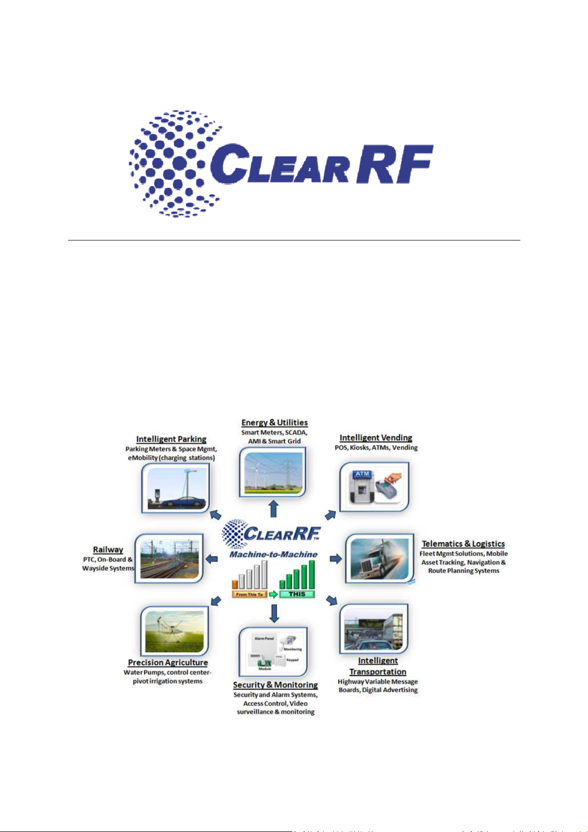
The WRE5500 M2M Cellular Amplifier is a high performance, microprocessor controlled, bidirectional RF
amplifier. The amplifier boosts signal in 5 Bands; 700Mhz, 850Mhz, 1900Mhz and 1700/2100Mhz which
covers all North American Carrier frequency bands. The
control system that will automatically adjust the gain and the output power if a signal anomaly occurs.
This amplifier is designed to operate as a direct connect unit within an M2M cellular system, for
m performance in weak signal coverage areas. The input power requirements for the amplifier
are positive 9.5 to 32.0 volts DC (negative ground).
................................
................................
................................
................................
................................
................................
................................
................................
................................
................................
................................
................................
................................
................................
amplifier has an automatic gain and oscillation
Overview ................................
................................
................. 2
Parts List ................................
Installation Guide
Installation with an SMA Device
Installation with an SMA Device
LED Diagnostics
Diagnostic LED definitions
Optional Accessories
Passive Bypass Technology –
WRE5500 Specifications
Safeguard Features
Antennas ................................
Warranty Information
................................
................................................................
Fixed Location ................................
- Fixed Location ................................
Mobile Location ................................
................................................................
................................
................................
................................
................................
................................
................................
................................
................. 3
.... 4
...................... 4
................... 5
................... 7
....... 8
....................... 9
............................... 9
........................... 9
.......................... 9
................................ 11
............... 11
........................... 11
Overview
maximu
MAN-5601-001 Rev 3
2
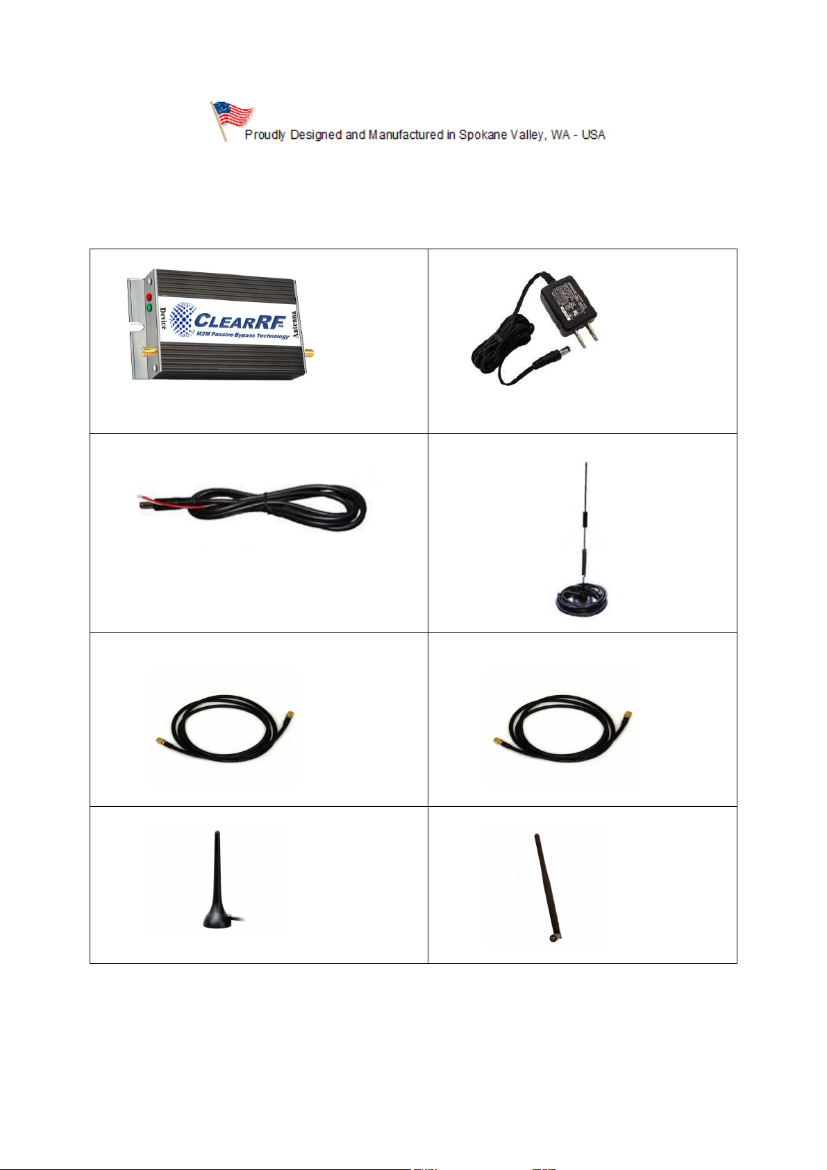
Parts List
Depending upon the connector type of the cellular device, ClearRF can customize the M2M kit to i
the appropriate adapters to ensure a
SMA, MMCX, MCX, FME
1. WRE
550
0 Amplifier Unit
3. Hardwire DC Power Cable
5. SMA
-to-
SMA Device Cable
7. Optional Low Profile Mag
and quick installation. Adapter types include
2. AC/DC Power Adapter
4. Magnetic
-
Mount
–If
connecting to
6. Optional
–
SMA
-
to
If connecting to an MMCX device.
-
Mount Antenna
8. Optional
– Elbow Antenna
Signal Antenna
-
MMCX Device Cable
–
limited to SMA, RP-
seamless
, and TNC.
nclude
, but are not
an SMA device
MAN-5601-001 Rev 3
3
Installation Guide
Installation of this device requires knowledge of basic electrical and
experience with installing electronic devices. We recommend seeking a
professional installer if you are not accustomed to installing electronics or high
Installation of th
assumes no responsibility for the installation or improper operation of this
device. Contact your dealer or
Help” in the subject line for assistance.
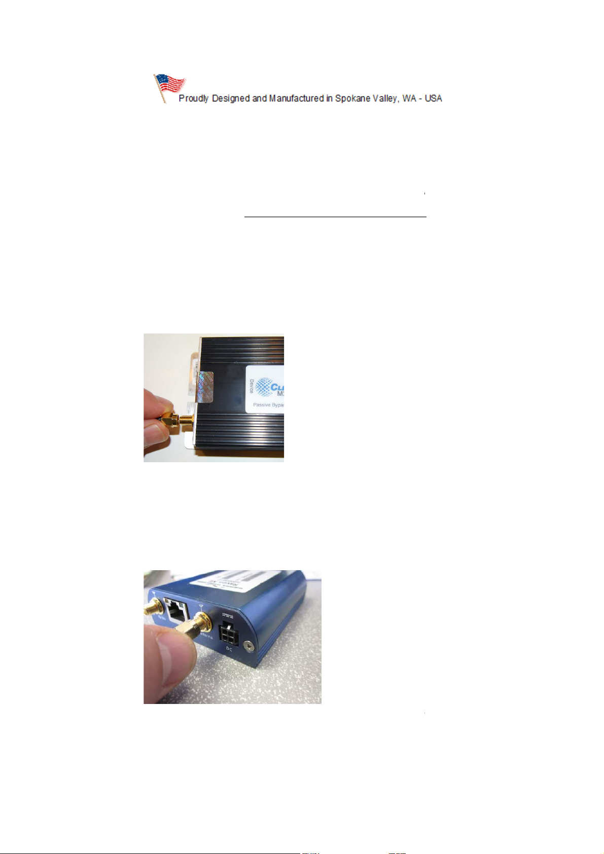
Installation with an SMA Device
a Cellular Modem (
) to the ClearRF Amplifier co
Connect the SMA end of the SMA
Ensure the cellular modem is powered off before connecting.
Outdoor Signal A
vice is at your own risk. Clear
CustomerService@ClearRF.com
), connect the SMA
able to the Cellular Modem
any metal surface.
Disclaimer:
tech devices.
1. If connecting to
(#5 on Parts List
2.
connection.
is de
- Fixed Location
e.g. Raven X, CradlePoint
nnector marked “Device”.
to SMA device c
RF, LLC
with “Installation
to SMA device cable
antenna
3. Mount the
MAN-5601-001 Rev 3
ntenna (#4 on Parts List) vertically on
4
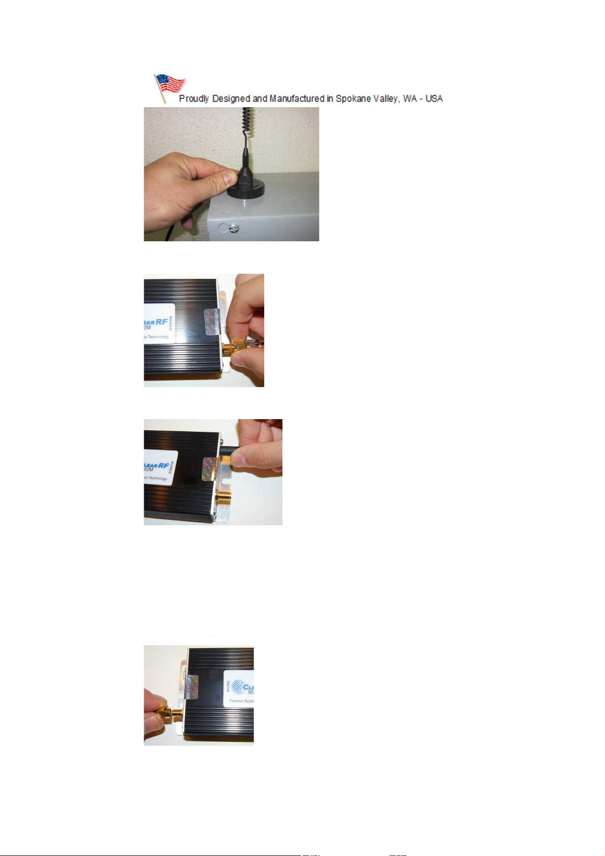
a. Connect the
Outdoor Signal
(#2 on Parts List)
connector
Power on the cellular modem.
Installation with an MMCX Device
Module
on Parts List) to the ClearRF Amplifier co
ClearRF amplifier
the LED indicators.
), connect the
Device
marked “Antenna”.
4. Plug the AC Adapter
5. Insert the AC Adapter
Antenna connector to the
into a nearby wall outlet.
plug into the amplifier and watch
SMA connector
6.
1. If connecting to a Cellular
device cable (#6
MAN-5601-001 Rev 3
- Fixed Location
(e.g. Motorola, Sierra Wireless
nnector marked “
SMA-to-MMCX
.”
5

2. Connect the MMCX
end of the
Mount the Outdoor Signal Antenna (#4 on Parts List) vertically on any metal surface.
the Outdoor Signal Antenna connector to the ClearRF amplifier
Plug the AC Adapter (#2 on Parts List) into a nearby wall outlet.
Insert the AC Adapter connector plug into the amplifier and watch the LED indicators.
able to the Cellular M
3.
4. Connect
“Antenna”.
SMA to MMCX device c
odule.
SMA connector marked
5.
6.
MAN-5601-001 Rev 3
6

In
stallation with an SMA Device
If connecting to a Cellular Modem
ile application, connect the SMA
Amplifier connector marke
Connect the SMA end of the
connection. Ensure the cellular modem or Mobile Data Terminal is powered off before
Mount the Outdoor Signal Antenna (#4 on Parts List)
hood or trunk of the vehicle.
(e.g. Raven X, etc
to SMA device cable (#5 on Parts List) to the ClearRF
SMA device cable to the Cellular Modem
vertically on any metal surface on the roof,
1.
mob
2.
connecting.
- Mobile Location
or Mobile Data Terminal
d “Device”.
SMA-to-
) in a vehicle or
or MDT antenna
3.
MAN-5601-001 Rev 3
7

4. Connect
the Outdoor Signal Antenna connector to the ClearRF amplifier
Plug the 12V Hardwire DC Cable (#3 on Parts List) into the vehicle
the red wire to a positive terminal from the fuse panel with a 3 ampere fuse rating. The black
wire should be attached to a ground of the vehicle. Power may also be provided to the amplifier
using a 12V cigarette lighter adapt
Hard Wire DC Cable
Power on the cellular modem or mobile data terminal.
Once the amplifier is installed pro
the green LED flashing. The green LED will flash while the amplifier increases its gain to the optimum
level. The red LED may also flash during this stage while the gain (power) is properly set on the
ower control is established, the green LED will remain constantly on. You may see
the green and red LEDs flash back and forth, THIS IS NORMAL. In areas where the cellular network is
adequate, the amplifier will maintain a maximum power level acceptable for
prevent overloading the wireless phone, as well as keeping RF signal levels at a minimum for a
If the red LED is constantly on and the green LED is off, the amplifier has
The amplifier will
reposition the antenna until normal operation is achieved.
you may permanently mount the antennas in the locations you chose in the prior steps.
fuse block. You must connect
or. (not included, available at www.clearrf.com)
connector plug into the amplifier and watch the LED indicators.
he LEDs will both turn on followed by
automatically and restart. If the fault persists,
Once normal operation is established,
“Antenna”.
5.
SMA connector marked
6. Insert the
7.
LED Diagnostics
amplifier. When p
perly and power is applied, t
normal operation and
healthy environment.
detected a fault.
MAN-5601-001 Rev 3
shut down
-
8

Diagnostic LED d
efinitions
LED test, the unit is initializing
Normal operation
Normal operation, increasing gain setting
Solid Green and Flashing Red
nd no Green
for pricing and availability or see your Clear RF
parts and additional accessories may also be available.
Passive Bypass Technology
amplifier is equipped with ClearRF’s Passive Bypass technology. This feature allows the
amplifier to passively bypass itself and become merely a pass through cable when amplification is not
necessary, during loss of power or when a fault is det
Passive Bypass technology is useful in applications where the amplifier is mobile, moving in and out of
poor signal areas. The amplifier will bypass itself when close to cell towers, completely eliminating any
potential for network disrupting noise
technology is also extremely useful in fire and security system installations where a connection with the
antenna must always be maintained, even with loss of power.
Specifications
Band 17
715, 77
746, 746
Rated Uplink Maximum Output Power: 27dBm
Rated Downlink Maximum Output Power:
Current Draw @ 12VDC: Idle: 275
Power Requirement: 8.0 to 32
Input/output Impedance: 50 Ohms
Rated Mean Output Power: 27dBm
This device complies with Part 15 of the FCC Rules. Operation is subject to the following two conditions: (1
device may not cause harmful interference, and (2
interference that may cause undesired operation.
Normal operation, decreasing gain setting
power caused by too much amplification near a cell tower. The
.0 volts DC (negative ground), Connector is center positive
device must accept any interference received, inclu
1. Solid Green and Red –
2. Solid Green –
3. Flashing Green –
4.
5. Solid Red a
Optional Accessories
Contact us at www.clearrf.com
–
– Fault detected (Passive ByPass is engaged)
™
dealer. Replacement
Patented
The WRE5500
WRE5500
• Frequency Range:
• Uplink (MHz) 698-
• Downlink (MHz) 728-
•
•
•
•
• Nominal Gain: 15dB
•
•
FCC ID: XS7WRE5500
IC ID: 8918A-WRE5500
ected.
, Band 13, Band 5, Band 2, Band 4
6-787, 824-849, 1850-1915, 1710-1755
-757, 869-894, 1930-1995, 2110-2155
-20dBm
milliamperes; Max: 1 amperes
) this
) this
ding
MAN-5601-001 Rev 3
9

The term “IC:” before the radio certification number only signifies that Industry of Canada technical
The Manufacturer's rated output power of this equipment is for single carri
operation. For situations when multiple carrier signals are present, the rating would have to be reduced by 3.5
dB, especially where the output signal is re
ns of input power or gain reduction and not by an attenuator at the output of
La puissance de sortie nominale indiquée par le fabricant pour cet appareil concerne son fonctionnement avec
porteuse unique. Pour des appareils avec porteuses
surtout si le signal de sortie est retransmis et qu'il peut causer du brouillage aux utilisateurs de bandes
adjacentes. Une telle réduction doit porter sur la puissance d'entrée ou sur le gain, et n
moyen d'un atténuateur raccordé à la sortie du dispositif.
FCC Regulatory Guidance: ClearRF’s WRE
Federal Communications Commission (FCC). For more information
225
The following selected information about wireless providers’ Consumer Booster registration
mechanisms supplements the requirements and information given in §§ 20.21, 22.9, 24.9, 27.9, and the
FCC Signal Boosters website (http://wireless.fcc.gov/signal
Sprint Nextel will allow consumers to register their signal boosters by calling their toll
They have already trained their calling center and have designated an engineer to handle inquiries.
Mobile online registration link: (ww
mobile.com/sites/SignalBooster#
Verizon’s online registration link: (
AT&T will allow online registration and will inform OET Lab with the weblink when it is ready.
U.S.Cellular (http://www.uscellular.com/uscellular/support
radiated and can cause interference to adjacent band users. This
multiples, on doit réduire la valeur nominale de 3,5 dB,
S operates under the rules and regulations as provided by the
e rules and regulations, please
https://saqat.t
http://www.verizonwireless.com/wcms/consumer/register
registration.jsp).
specifications were met.
power reduction is to be by mea
the device.
contact the FCC directly at (888)-
er
-
e doit pas se faire au
550-
on thes
-5322.
-boosters/).
•
• T-
w.T-Mobile.com/BoosterRegistration); (
).
•
booster.html).
•
•
/fcc-booster-
MAN-5601-001 Rev 3
-free number.
-
-signal-
10

The amplifier has an automatic gain and oscillation control system that will automatically adjust
the gain and the output power if a signal anomaly occurs. This amplifier is designed to operate as a
ered (direct connect) unit within a cellular system, for maximum performance in weak signal
You MUST operate this device with approved antennas and cables as specified by the
manufacturer. Antennas MUST be installed as least 20
installation height of the antenna for AWS band (1700/2100 MHz) operations is limited to 10
meters above ground for compliance with Section 27.50
001 Mag Mount Antenna
001 Low Profi
001 Rubber Duck Elbow Antenna
Warranty Information
ClearRF L.L.C. warrants that this product is free from defects in materials or workmanship for one year from the date of purc
ClearRF, will, at its sole option, repair or replace any components which fail in normal use. Such repairs or
replacement will be made at no charge to the customer for parts or labor, provided that the customer shall be responsible for
ost. This warranty does not cover failures due to abuse, misuse, accident or unauthorized alterations or repairs.
Repairs have a 90 day warranty. If the unit sent in is still under its original warranty, then the new warranty is 90 days or
e original one year warranty, depending upon which is longer.
ClearRF retains the exclusive right to repair or replace the product or offer a full refund of the purchase price at its sole
Such remedy shall be your sole and exclusive remedy for
Procedure for Claims under Limited Warranties
To obtain warranty service, an original or copy of the sales receipt from the
To obtain warranty service, follow these two steps:
Contact ClearRF via email to receive authorization (RMA) number at warranty@clearrf.com
Once you have obtained an RMA #, ship the unit, copy of the sales receipt, along with the RMA
cm (8 inches) from any person.
any breach of warranty. ClearRF shall not be liable for any incidental or
original retailer is r
Safeguard Features
teth
coverage areas.
Antennas
Antenna Options:
The
• MSE-5721-
• MSE-6000-
• MSE-6001-
Within this period,
transportation c
of th
consequential damages for breach.
le Mag Mount Antenna
Limited Warranty
hase.
any
to the end
discretion.
equired.
1.
2.
number to:
MAN-5601-001 Rev 3
11

ClearRF
, Suite 104
RMA #: {insert RMA number}
12825 E. Mirabeau Parkway
Spokane Valley, WA 99216
855-321-9527
Contact ClearRF at:
customerservice@clearrf.com
MAN-5601-001 Rev 3
12
 Loading...