

Page 1
WH5B
Iron / Hydrogen Sulfide
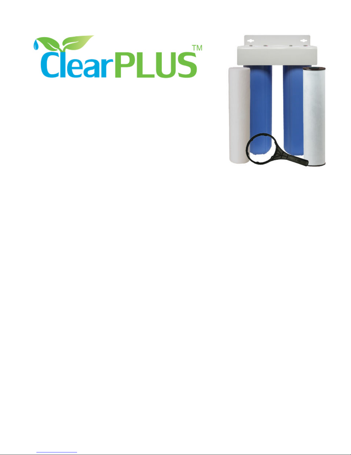
Reduction Filter Package
w/ Sediment Pre-Filter
Package Contents:
• two (2) heavy-duty Pentek Big Blue 20” filter housings (1” NPT) w/ pressure relief button
• one (1) powder-coated dual mounting bracket and related screws
• one (1) Pentek RFFE20-BB radial flow iron reduction filter cartridge
• one (1) Pentek DGD-5005-20 dual-gradient 5 micron sediment pre-filter
• one (1) spanner wrench
The WH5B iron / hydrogen sulfide reduction filter package contains manganese dioxide media
which reduces iron, manganese, and hydrogen sulfide through an oxidation / filtration process,
thereby substantially improving water clarity, taste, and odor, while at the same time protecting
your plumbing system including toilets, bath tubs and showers, and appliances such as clothes
washers and dishwashers, from unsightly staining. It does NOT add any harmful chemicals to the
water, making it completely safe for drinking water applications. A high-capacity 5 micron
sediment pre-filter extends the life of the primary iron filter by trapping sediments, debris, and
oxidized ferric iron particles to prevent pre-mature clogging.
This system should be employed where low to moderate ferrous (dissolved) iron, manganese, or
hydrogen sulfide contamination is known or expected. This filter will also remove ferric iron
through mechanical filtration. This filter is most effective where iron contamination level is less
than 3 ppm (and no greater than 5 ppm) or the hydrogen sulfide level is less than about 2 ppm. If
a combination of iron, manganese, and hydrogen sulfide are present, you must consider the "iron
equivalent" level when determining if this filter will work effectively in your circumstance (see
below). Best contaminant removal rates are achieved where the pH is 7.0 or higher, although
satisfactory contaminant removal can generally be achieved at slightly lower pH levels (6.8 to 6.9)
under most conditions. This filter is not recommended where pH levels are less than 6.8. For best
results, pre-sediment and post-carbon treatment is recommended. A pH level of 8.0 is desirable
for optimal manganese reduction.
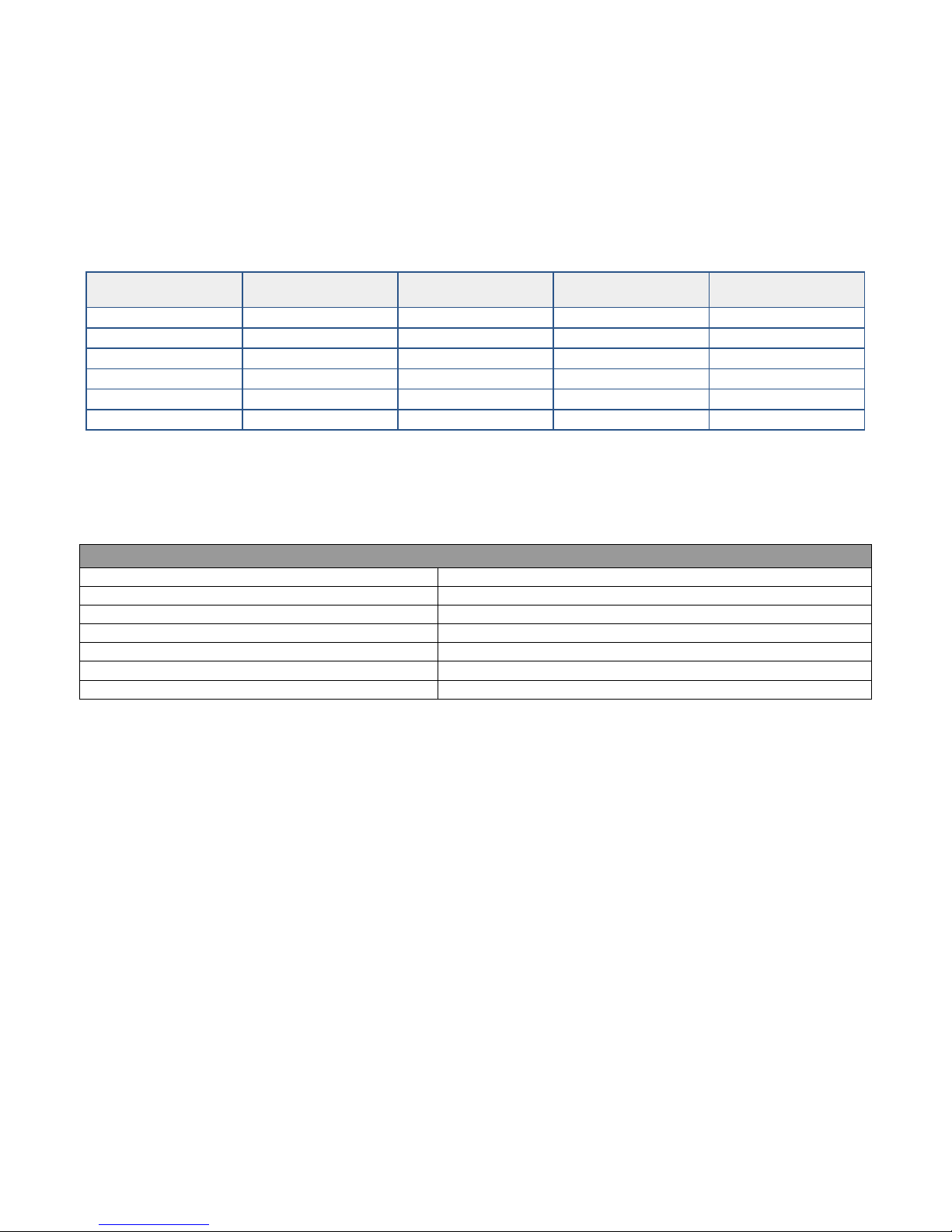
The life of the filter depends on the contamination level ("iron equivalent") and amount of water
consumed on a daily basis. You can get a good idea of how long a filter will last in your case by
using the chart below.
"Iron Equivalent" is calculated as follows:
Page 2
(Iron level) + (2 x Manganese level) + (3 x Hydrogen sulfide level)
If your level of Hydrogen sulfide is unknown (it is hard to accurately test for) and you have a
noticeable "rotten egg" odor, assume a Hydrogen sulfide level of 0.5 ppm. If the rotten egg odor
is severe, assume a level of 1.0 ppm.
Example: Test results are 0.8 ppm iron, 0.05 ppm manganese,
and you have a rotten egg smell in your water. Iron Equivalent = (0.8) + (2 x 0.05) + (3 x 0.5) = 2.4
Approximately life of a RFFE20-BB filter cartridge:
Iron Equivalent
Level in Water
5 ppm 16,000 gal 64 days 128 days 256 days
4 ppm 20,000 gal 80 days 160 days 320 days
3 ppm 26,000 gal 104 days 208 days 416 days
2 ppm 40,000 gal 160 days 320 days 640 days
1 ppm 80,000 gal 320 days 640 days 1280 days
0.5 ppm 160,000 gal 640 days 1280 days n/a
Total Gallons
Water Used
250 GPD
(four people)
125 GPD
(two people)
75 GPD
(one person)
How it Works: Soluble iron (ferrous) and manganese are oxidized and precipitated by contact
with higher oxides of manganese on the media granules. The hydrogen sulfide is reduced by
oxidation to an insoluble sulfur precipitate. The precipitates are then filtered. Ferric iron is
removed by mechanical filtration. No backwashing required!
Specifications
Housing Material: Polypropylene
Housing O-Ring Material: Buna-N
Housing Pressure Drop (each): 1 PSI at 15 Gallons Per Minute (0.1 bar at 57 LPM)
Filter Pressure Drop: <3 PSI @ 6 Gallons Per Minute (<0.2 bar @ 23 LPM)
Maximum Recommended Flow Rate: 6 Gallons Per Minute (23 LPM)
Recommended Operating Temp. Range: 40-100˚F (4.4 to 37˚C)
Maximum Recommended Pressure: 90 PSI (6.2 bar)
Typical Installation:
Note: We recommend that this product be installed by a professional plumber. If you
install this product yourself, please ensure that your installation meets all local building
and plumbing codes. The following instructions are meant only as a general guide and
should not be considered a substitution for your local plumbing and / or building codes.
You will need the following plumbing supplies:
• two (2) shut-off valves with suitable sized unions to connect to your incoming and outgoing
water lines. You can select threaded, compression or sweat (soldered) fittings on the shut-
The plumbing connections on the inlet and outlet of the water filter housings are 1” inside
diameter (female) NPT threaded fittings. You may require additional plumbing adapters to
connect to your selected shut-off valves. Your plumber will have all of these items, or they can be
purchased at your local hardware or plumbing supply store at minimal cost (take these
instructions to the store with you so the store clerk can make sure you get everything you need).
Note: In older homes with galvanized piping all fittings should be threaded.
off valves as desired.
• plumber’s cement or Teflon tape for all threaded fittings.
Page 3
STEP 1. Select an installation location. There are a variety of ways to install your filter system
into a main or branch water line. As a general recommendation, this system should be installed
on the main cold water line after the pressure tank or water meter. Select an installation
location with convenient access for regular filter replacements and maintenance.
STEP 2. Shut off the main water supply and drain the pipes. Opening the highest and lowest
fixtures in the house will help drain the pipes.
STEP 3. Using a pipe cutter, cut out a section of your main water line at the point where you
want to install your filter system. There will probably be some water remaining in the system, so
be sure to have a bucket and some rags handy to clean up any small spills. Make sure that the
section of water line you remove is appropriately sized such that all of the components of the
system including the shut-off-valves, adapters, and the black filter caps will fit snuggly when
assembled. If in doubt, cut a smaller section at first – you can always remove a slightly larger
section upon final assembly if necessary.
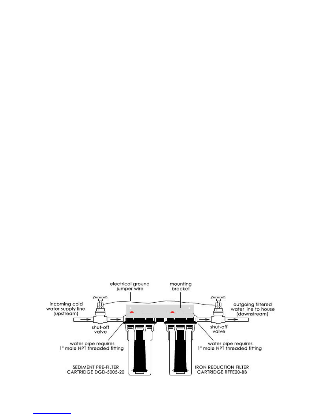
STEP 4. Assemble the components according to Diagram 1 below. Use the 1” housing coupler
provided with this package to connect the 2 black housing caps. We recommend installing shutoff valves both upstream and downstream of the filter housings. A shut-off valve is not required
on the upstream side of the housing if the filter will be located within a couple of feet of the main
line shut-off valve. Plumber’s cement or Teflon tape should be used on all threaded
fittings. Use the mounting bracket and screws provided so secure the black filter housing caps to
the wall or other solid surface. Allow enough space below the black cap to accommodate the blue
housing sumps plus a minimum of an additional 3 inches of clearance.
IMPORTANT WARNINGS:
Use extreme caution when soldering any connections between the main water line and
the shut-off valve or between the shut-off valves & filter housings if your filter housings
are connected to the pipes, or serious damage to the filter housings could occur. If at
all possible, solder all connections before the pipe is connected to the filter housings.
If your water pipes are metal (galvanized or copper), they may be used to ground
electrical systems, appliances, or your phone line. If this is the case, be sure to install
regulation ground clamps to the metal pipe on each side of the plastic filter housing and
connect a jumper wire between the 2 clamps (#4 gauge solid copper wire
recommended). Alternatively, your plumbing code MAY allow you to connect the
jumper wire to the 2 shut-off valves (see diagram). Consult a certified electrician or
plumber if you are unsure.
Diagram #1
Page 4

STEP 5. Remove the protective plastic wrap from one of the filter cartridges and place it in the
appropriate blue housing sump. At the bottom of the sump, there is a raised portion in the middle
(standpipe) that will help center the filter in the housing. The standpipe will fit inside the hole
that runs through the middle of the filter cartridge. Check to make sure that the O-ring is seated
properly in the grove at the top of the blue housing sump, then screw the blue housing sump
containing the filter cartridge onto the black housing cap. Use the spanner wrench to tighten.
Repeat this step for the other filter. Store any spare filters in a cool dry place for future use.
STEP 6. Turn on the water and inspect all plumbing connections very carefully for leaks. Also
inspect the seal between the black housing caps and the blue housing sumps to ensure that the
O-ring has formed a good seal. Tighten this connections again using the spanner wrench if
necessary. If this connection still leaks, turn off the water supply and check to make sure that the
filter is aligned properly in the housing and repeat your test for leaks. When you are confident
that all connections are sound, run cold water for 5 minutes at any faucet to purge air out of your
system and flush the filter before use. New cartridges may release “fines” (very fine black
powder) after installation. Wait one hour, and flush again for another 5 minutes prior to using the
water.
Important Notes:
1. The manufacturer recommends that the blue housing sumps be replaced every 10 years or if
you notice any cracks or damage.
2. This filter system should not be used with water that is microbiologically unsafe or of unknown
quality without adequate disinfection before and/or after the system.
3. Water filter systems should never be exposed to freezing temperatures - severe damage to the
filter and housings could result. Such damage is not covered under any warranty.
4. After prolonged periods of non-use (such as a vacation), it is recommended that the system be
flushed thoroughly for at least 5-10 minutes before using the water.
5. The contaminants or other substances removed or reduced by this water treatment device are
not necessarily in your water.
6. If you suspect that your water pressure will at any time exceed the maximum rating of 90 PSI
(6.2 bar), a pressure regulator must be installed before the system. It is recommended that the
pressure regulator be set at 75 PSI (5.2 bar) or less.
Maintenance and Filter Replacement Information:
To maintain the optimal performance of your whole house water filter system, filters should
always be replaced in accordance with manufacturer specifications. Filters may need to be
replaced more frequently then specified, depending on the level of contaminants, particularly
sediments, in your water supply. If significant water pressure reduction is noticed, the filter may
have become clogged. We recommend that you keep a “Filter Replacement Log” attached to your
system where you can record the date of filter changes, and that you write a note on your
household calendar reminding you of filter replacement schedules.
Replacement Filters: Pentek RFFE20-BB & Pentek DGD-5005-20
Replacement Filters can be Obtained as Follows:
Phone Toll Free 1-866-376-2690 or
Order Online at: www.home-water-purifiers-and-filters.com
Page 5

Filter Cartridge Replacement Procedure:
1. Turn off the water supply to the system using the shut-off valves you installed on the inlet
and outlet of the filter housing. Depress the red pressure release button on the top of the
filter housing cap to allow any pressure inside the housing to escape, thereby allowing the
blue filter sump to be removed easier.
2. Unscrew the blue sump (bottom of the housing) from the cap using your spanner wrench
(included with original purchase of your system).
3. Locate and remove the large O-ring. Try not to remove any of the lubricant. The housing
O-ring should be replaced at least once annually or at each filter change if any damage to
the O-ring is noted (kinked, cracked, stretched, etc.), or if any leakage between the black
housing cap and the blue housing sump is detected and does not seal after tightened with
the spanner wrench. Put the O-ring in a safe place where it will not get dirty or otherwise
contaminated. Replacement O-Ring: Pentek Buna-N Big Blue O-Ring #151122
4. Take out the old filter cartridge and discard it.
5. Scrub the bottom of the housing and cap with dish soap and warm water using a sponge or
soft cloth. Fill 1/3 with water and add about 2 tablespoons of household bleach. Scrub to
disinfect (we recommend that you use rubber gloves). Rinse all parts thoroughly!
6. Lubricate the O-ring with food-grade silicon lubricant if needed. Insert O-ring in the
groove at the top of the blue sump and press into place. Make sure the O-ring is
seated level in the groove!
7. Remove the protective plastic wrapping from the new filter cartridge and insert the
cartridge into the housing sump, making sure that it slips over the standpipe in the bottom
of the housing.
8. Screw the blue sump onto the black housing cap tighten using the spanner wrench. Do
not over tighten.
9. Turn on the water supply slowly to allow the system to fill with water. Depress the red
pressure release button on top of the unit again to release any trapped air. Inspect
carefully for leaks. If a leak is found, first inspect the O-ring to ensure that it is seated
properly before tightening the sump more. Tighten using the spanner wrench as necessary
to achieve a good seal and stop leaks.
10. New cartridges may contain “fines” (very fine black powder) after installation. Flush the
system by running water from a nearby faucet for 5 minutes. Wait one hour, and flush
again for another 5 minutes prior to using the water.
 Loading...