

Page 1
StreamNet™ Digital Media and
System Design Reference Guide
Page 2

Table of Contents
Introduction ....................................................................................................3
Common AV Signals and Inter faces .............................................................5
What is StreamNet? ....................................................................................17
StreamNet Audio Technology .....................................................................24
Digital File Security and (DRM) ...................................................................26
HDCP Quick FAQ .........................................................................................31
Public Performance Rights ..........................................................................35
Designing a StreamNet System, introduction to required devices ...........41
Designing a StreamNet System, example configurations .........................47
StreamNet Products ....................................................................................50
AVoIP Video Encoder Feature Comparison Matrix .....................................55
View Decoder Comparison Chart ...............................................................57
Motion XT Use Chart ...................................................................................57
Encoders vs. Decoders Compatibility Matrices .........................................58
Example StreamNet System Design ...........................................................63
StreamNet FAQ ............................................................................................64
Solving Digital Media Related AV Problems ...............................................69
Glossary .......................................................................................................78
pg 2StreamNet Digital Media and System Design Reference Guide
Page 3
The purpose of this reference guide is to provide valuable information on digital media
technologies for the AV dealer seeking to better understand how to make the transition
from analog based media formats and transports, to digital. Though comprehensive in
nature we recommend further study if the concepts and terms covered are new. ClearOne’s
StreamNet solutions are highly capable and scalable, allowing traditional system design
concepts to be challenged by offering more flexibility, higher quality and in many cases
costs savings.
Introduction
pg 3 StreamNet Digital Media and System Design Reference Guide
Page 4

Introduction
We believe AV systems should no longer be analog.
+ Sources are digital. This doesn’t mean a modern audio video source won’t have
analog connectors. But since the program material is rendered digitally, it no longer
makes sense to convert the pristine quality of a digital file back to analog. Hence the
longer an AV systems designer is able to keep the digital signal intact, the better the
sound and picture quality will be.
+
Displays are digital. With the advent of digital fixed pixel displays and projectors,
the highest quality picture is possible when the content stream remains digital and is
not converted to analog. Though a reasonable quality picture is possible to achieve
with analog equipment, there are resolution and cabling limitations, which can greatly
degrade the end result.
+
Greater signal lengths without loss or degradation with digital. By transmitting
digital signals over Internet Protocol (IP) rather than analog or RF based distribution
methods, signal distances of several miles may be achieved with virtually no image
degradation or signal loss. This compared to mere hundreds of feet with analog where
image degradation can suddenly become a significant issue.
+
Mass exposure to HD and 3D program material has greatly raised consumer
expectation for AV system performance.
increasing sound and picture quality in nearly every arena. HDTV products and
program material is highly penetrated in the home. OEM automobile sound systems
are at the highest performance level they have ever been. Which along with ever
improving retail, and commercial AV system quality, means the average consumer has
a reasonably good understand of what constitutes good audio and video performance.
+
Wireless technologies improve installation flexibility. With new state of the art
wireless systems, the digital signal remains intact from the source to the transmitter to
the receiver to the speaker or display. This means AV systems designers have choices
in infrastructure that can lower or reduce the high cost of cabling or installation difficulty
when designing high performance audio video systems.
+
Cost benefits compared with extensive cabling costs and labor for large
installations.
type. However with IP based AV systems, a single Category 5 cable may carry the
load of several dozen audio channels along with multiple video streams and all control
signals. This reduces not only cable cost but also installation labor.
With analog systems, generally a single cable may only carry one signal
Consumers are presented with ever
pg 4StreamNet Digital Media and System Design Reference Guide
Page 5
Common AV Signals and Interfaces
It is important to note that there is a difference between a file format and a codec. The job
of a digital codec is to perform the encoding and decoding of the raw audio data. While the
data itself is stored with a specific audio format in a file. Although most audio file formats
support a single type of audio data that is created with an audio coder, a multimedia
container format such as MKV or AVI may support multiple types of audio and video data.
Interfaces on the other hand commonly define a physical connectivity standard by which
various signals may be interconnected. Following are a few of the most common interface
types found in audio, video, network and control systems.
Digital Audio
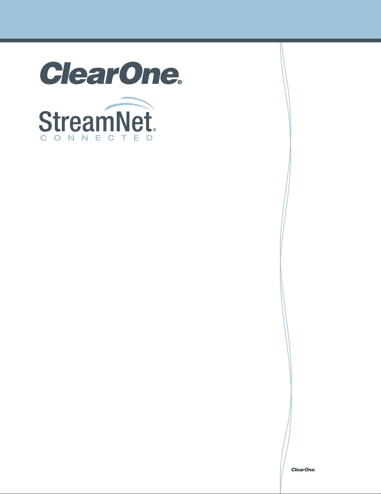
AES/EBU - The digital audio standard frequently called AES/
EBU is officially known as AES3 and is used for carrying digital
audio signals between various devices. Several different
physical connectors are defined as part of the overall group of
standards such as IEC 60958 Type I Balanced – 3-conductor,
110-ohm twisted pair cabling with an XLR connector, used in
professional installations (AES3 standard). The IEC 60958 Type
II Unbalanced – 2-conductor, 75-ohm coaxial cable with an
RCA connector is often used in consumer audio applications.
Finally, IEC 60958 Type II Optical – optical fiber, usually plastic
but occasionally glass, with an F05 connector, may also be
found in consumer audio applications.
Toslink Optical
S/PDIF - A related system to AES/EBU, S/PDIF was developed
as a consumer version using connectors more commonly
found in the consumer market such as RCA connectors in
the case of 2-conductor 75-ohm coaxial cable. S/PDIF also
supports optical fiber termination and is found widely in
consumer applications.
pg 5 StreamNet Digital Media and System Design Reference Guide
XLR
RCA
Page 6
Common AV Signals and Interfaces
Digital Video
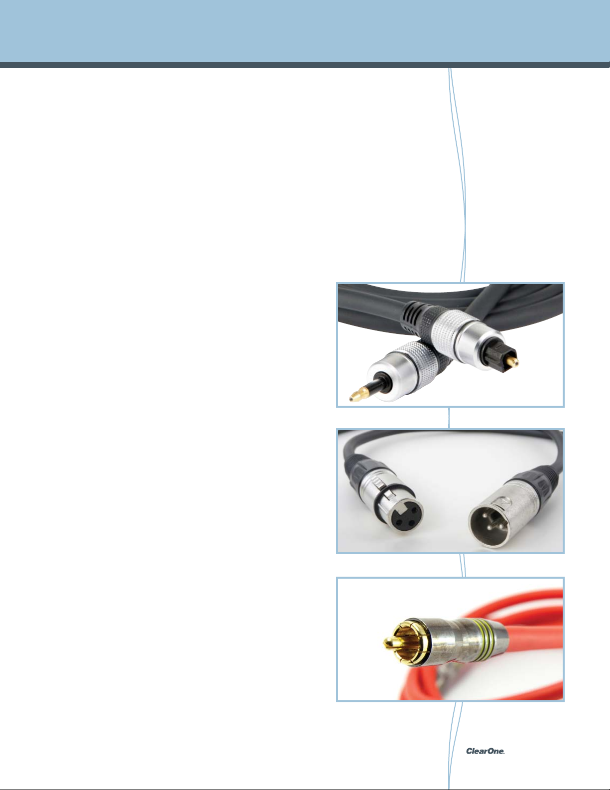
HDMI – High-Definition Multimedia Interface (HDMI) technology
is a global standard for connecting high-definition products.
With HDMI’s uncompressed all-digital interface the viewer
receives both dazzling quality and ease of use. Well over 1,000
manufacturers incorporate HDMI connectivity into a growing
list of consumer products from HDTVs, Blu-ray Disc Players,
Gaming systems, Digital video cameras, Mobile devices and
more.
HDMI
The flexibility of HDMI is in the single cable capable to transmit digital video, digital audio,
and control data through a high-speed link.
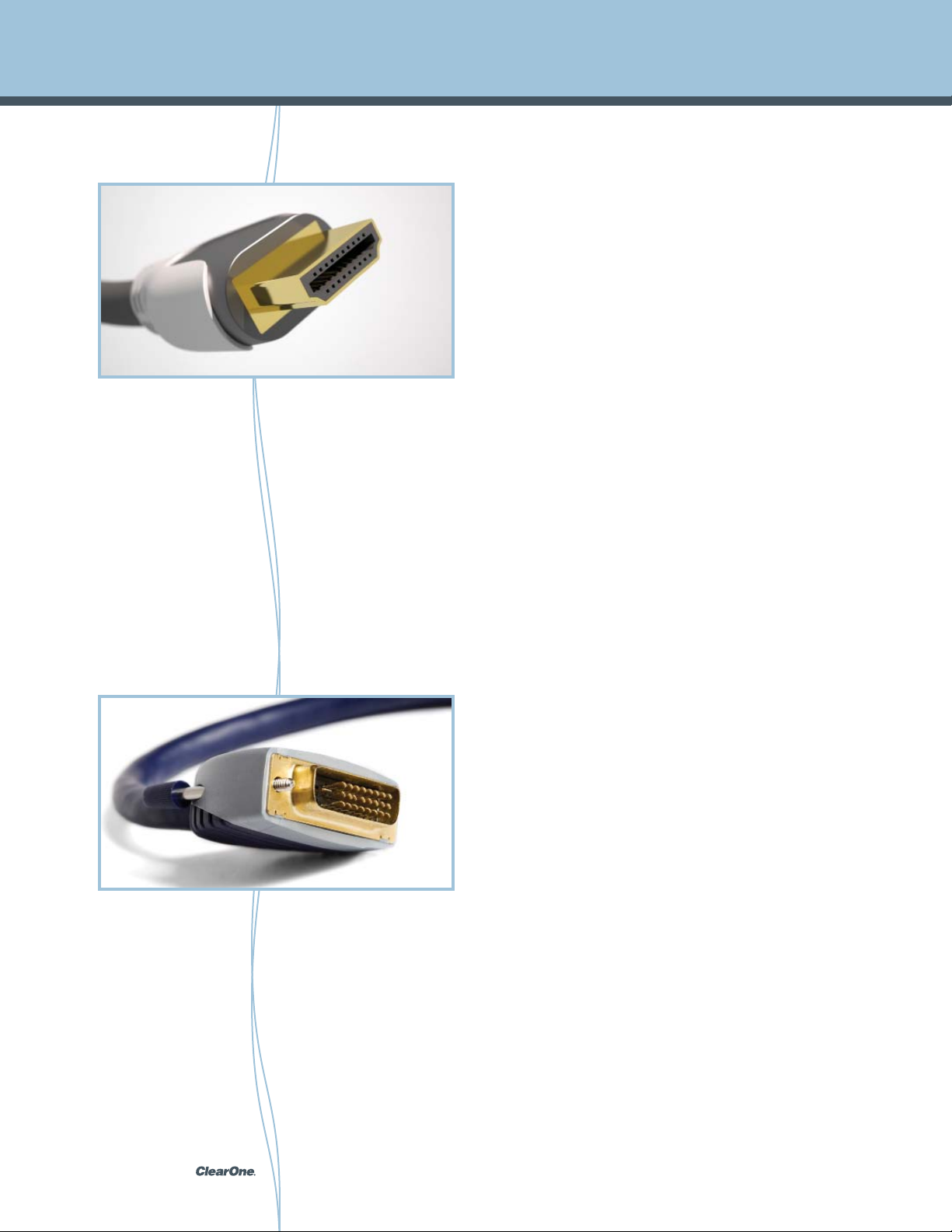
DVI
HDMI offers
twice the bandwidth needed to transmit an uncompressed 1080p signal. This enables
better looking movies, faster game play, richer audio, 3D movies and gaming. Additional
benefits include higher resolution support beyond 1080p such as 1440p or Quad HD, faster
refresh rates like 120Hz or beyond and deep color, taking the HDTV display palette from
millions to trillions of colors. It should also be noted that HDMI specifies a robust digital
rights management scheme (DRM) known as HDCP. For this reason premium content
owners allow full HD output typically over HDMI only and not analog interfaces such as
component video.
Multimedia Interface (HDMI) standard in digital mode (DVI-D), and VGA in analog mode
(DVI-A) some devices will display a digital signal originating from a DVI connector but
terminating to an HDMI port. However, care must be taken in mixing and matching the
standards as certain data types and signals are not fully supported by DVI, but may be
supported by HDMI.
enormous bandwidth capacity of up to 10.2 gigabits per second, more than
DVI - The Digital Visual Interface (DVI) is a video interface
standard designed to provide high quality direct digital
connection of source devices to digital display devices such
as flat panel LCD computer displays and digital projectors.
DVI was developed by an industry consortium, the Digital
Display Working Group (DDWG) to replace the “legacy
analog technology” VGA connector standard and is designed
for carrying uncompressed digital video data to a display.
Because it is partially compatible with the High-Definition
pg 6StreamNet Digital Media and System Design Reference Guide
Page 7
Common AV Signals and Interfaces
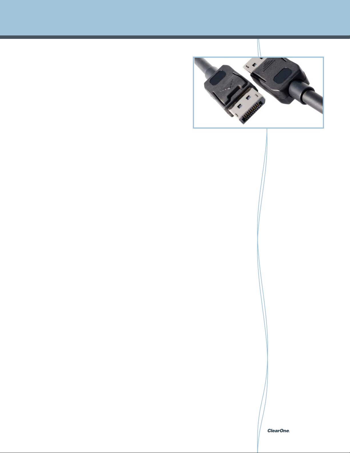
DisplayPort - DisplayPort is a digital display interface standard
put forth by the Video Electronics Standards Association (VESA)
which defines a digital audio and video interconnect scheme
intended primarily for use between a computer and its display.
DisplayPort is designed to replace digital (DVI) and analog
component video (VGA) connectors in computer monitors and
video cards. As well as replace internal digital LVDS links in
computer monitor panels and TV panels. Though DisplayPort
can provide the same functionality as HDMI it is not expected to
displace HDMI in high-definition consumer electronics devices.
DisplayPort includes optional DPCP (DisplayPort Content Protection) which is licensed from
Philips and uses 128-bit AES encryption. It also features full authentication and session key
establishment along with an independent revocation system, something that is considered
essential by premium content owners such as Hollywood studios. Later versions of
DisplayPort beginning with version 1.1 added support for the industry-standard 56-bit HDCP
(High-bandwidth Digital Content Protection) revision 1.3
DisplayPort
pg 7 StreamNet Digital Media and System Design Reference Guide
Page 8
Common AV Signals and Interfaces
Network
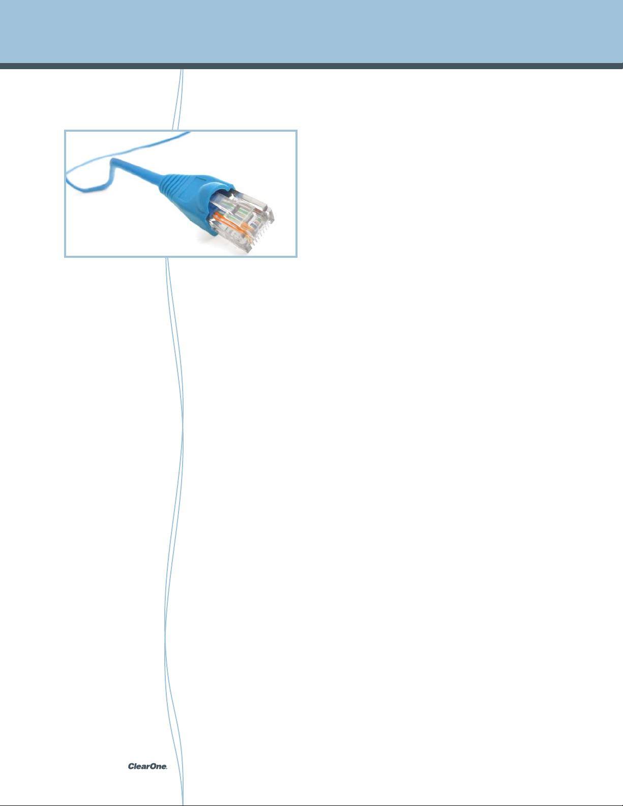
Ethernet - Modern Ethernet networks are now able to easily
carry data and StreamNet signals simultaneously without
difficulty. This fact reduces cost for the AV systems designer
choosing IP audio / video systems as separate networks and
cabling no longer need to be installed.
Ethernet defines wiring and signaling standards for the Physical
Layer of the OSI networking model as well as a common
RG45 Ethernet
procedures at the lower part of the Data Link Layer. Evolutions include higher bandwidth
support, improved media access control methods, and changes to the physical medium
which has caused Ethernet to evolve into a complex networking technology. Ethernet
stations communicate by sending each other data packets, blocks of data that are
individually sent and delivered. As with other IEEE 802 LANs, each Ethernet station is given
a 48-bit MAC address. MAC addresses are used to specify both the destination and the
source of each data packet. Despite the significant changes in Ethernet over the years, all
generations of Ethernet (excluding early experimental versions) use the same frame formats
(and hence the same interface for higher layers), allowing them to be readily interconnected.
addressing format, and a variety of Medium Access Control
Ethernet network interconnection options:
pg 8StreamNet Digital Media and System Design Reference Guide
Page 9
Common AV Signals and Interfaces
Category 5 / 6 Cable
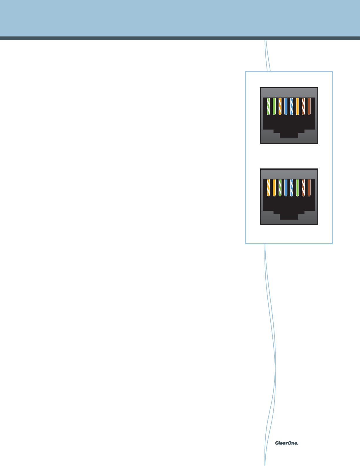
Category 5 (Cat 5) cable for use in networks is tested for reliable transfer of signal
frequencies up to 100 MHz. Category 5 cable is terminated in either the T568A
scheme or the T568B scheme. Canada and Australia use the T568A standard,
and the U.S. commonly uses T568B scheme. Both schemes work equally well and
may be mixed in an installation so long as the same scheme is used on both ends
of the cable. An interesting fact regarding Category 5 network cable termination
is that 8P8C modular connectors are used but are often incorrectly referred to as
“RJ-45”. Of the four pairs of wire found in a Category 5 cable, each has differing
precise number of twists based on prime numbers so as to minimize crosstalk and
improve signal integrity. The pairs are made from 24 gauge (AWG) copper wires
within the Cat 5 cable standard. Although, cable assemblies containing 4 pairs are
common, Category 5 is not limited to 4 pairs. In fact backbone applications may
use up to 100 pairs.
12345
T568A
678
A newer cable standard known as Category 6 (Cat 6), is the cable standard
for Gigabit Ethernet and is backward compatible with the Category 5/5e and
Category 3 cable standards. Compared with Cat 5 and Cat 5e, Cat 6 features
more stringent specifications for crosstalk and system noise reduction. Category
6 provides performance of up to 250 MHz and is suitable for 10BASE-T, 100BASE-
TX (Fast Ethernet), 1000BASE-T/1000BASE-TX (Gigabit Ethernet) and 10GBASE-T
(10-Gigabit Ethernet).
12345
T568B
678
pg 9 StreamNet Digital Media and System Design Reference Guide
Page 10
Common AV Signals and Interfaces
HTTP
FTP
TLS/SSL
Application Layer
TCP
UPD
Transport Layer
ICMP
IGMP
Internet Layer
ISDN
Ethernet
Link Layer
Internet Protocol Suite Layers
SMTP
POP
IMAP
REQUEST
IP
ANSWER
DSL
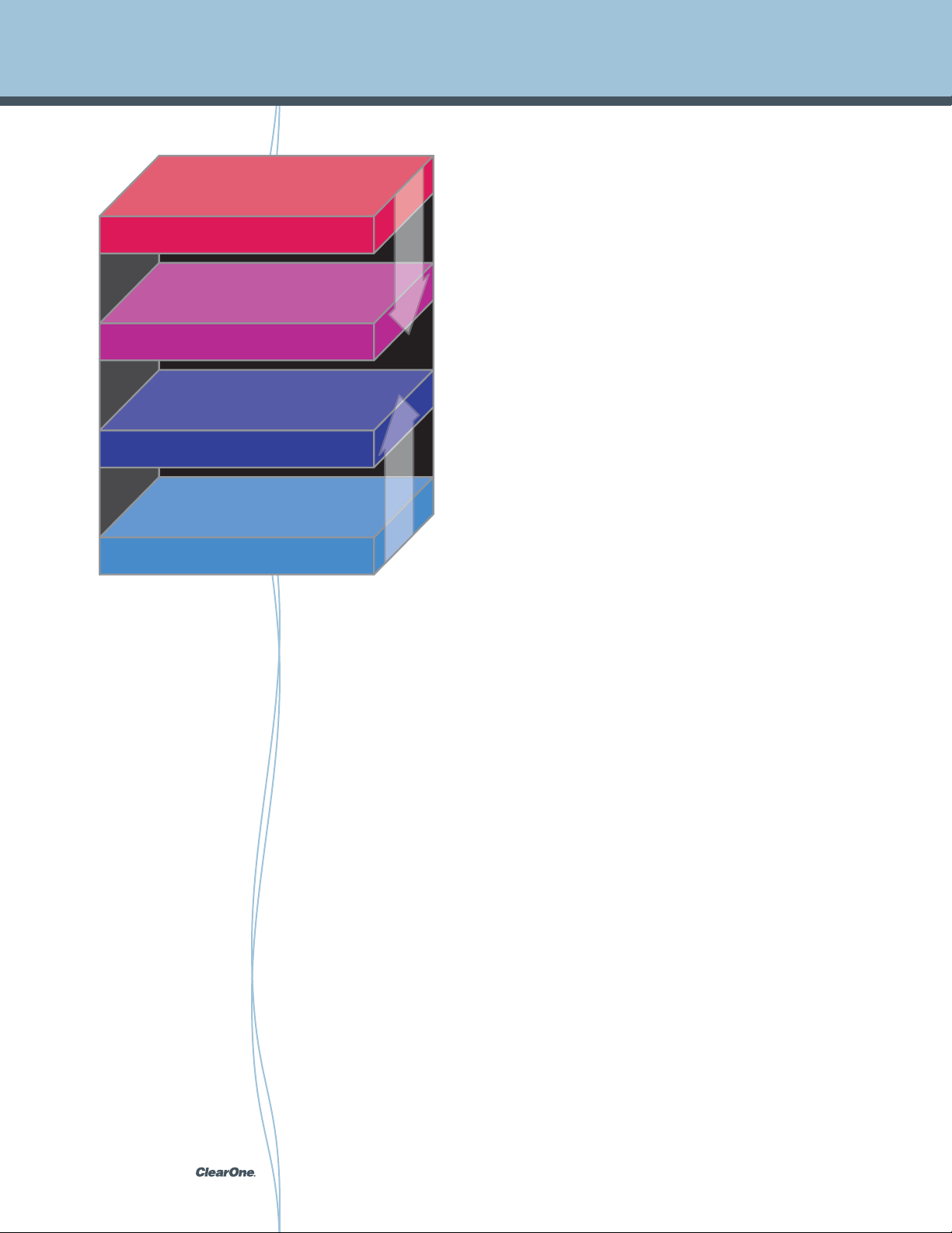
computer and facilitates the interconnection of networks. This layer establishes the Internet
and contains primarily the Internet Protocol, which defines the fundamental addressing
namespaces. Internet Protocol Version 4 (IPv4) and Internet Protocol Version 6 (IPv6) are
used to identify and locate hosts on the network. Direct host-to-host communications are
handled in the Transport Layer which provides a general framework to transmit data between
hosts using protocols like the Transmission Control Protocol. The highest-level Application
Layer contains all protocols defined specifically for the functioning of the vast array of data
communications services. This layer handles application-based interactions on a process-
to-process level between Internet hosts that are communicating.
TCP/IP – The Internet Protocol Suite is a set of communications
protocols used for the Internet. It is also known as TCP/IP named
from two of the most important protocols contained in it, the
Transmission Control Protocol (TCP) and the Internet Protocol
(IP). Modern IP networking represents a synthesis of several
developments which evolved in the 1960s, 1970s, and emerged
during the 1980s, together with the advent of the World Wide Web
in the early 1990s.
The Internet Protocol Suite consists of four layers from the lowest
to the highest layer these are the Link Layer, the Internet Layer,
the Transport Layer, and the Application Layer. Each layer defines
the operational scope or reach of the protocols and are reflected
loosely in the layer names. Each layer has functionality which
solves a set of problems relevant to its scope.
The Link Layer contains communication technologies for the local
network where the host is connected to directly. The Internet Layer
describes communication methods between multiple links of a
pg 10StreamNet Digital Media and System Design Reference Guide
Page 11
Common AV Signals and Interfaces
MoCA (Multimedia over Coax Alliance)
Using Coaxial cable, MoCA is the only home entertainment networking standard in use
by cable, satellite and IPTV operators and equipment providers. The current MoCA
specification can support multiple streams of HD video, delivering up to 175 Mbps
throughputs while offering unparalleled user experience via parameterized quality of service
(PQoS). Though primarily implemented for transportation of digital entertainment files,
MoCA fully supports Ethernet and thus is an excellent way to transfer data of any type with
no limitations. MoCA is a popular solution in any installation where coaxial cable may be
already installed thus negating the need to pull new wire. For AV installers working with
residential projects we recommend MoCA as a cost effective way to distribute StreamNet
and Ethernet signals. The Multimedia over Coax Alliance (MoCA®) features more than 80
certified products and is the universal standard for home entertainment networking. For
information on MoCA and compatible products visit: http://www.mocalliance.org/
HomePlug AV (Powerline Alliance)
The purpose of HomePlug AV (HPAV) is to provide high-quality, multi-stream, entertainment
data transfer using Ethernet standards over existing AC wiring. HPAV employs advanced
PHY and MAC technologies to provide a 200 Mbps class powerline network for video,
audio and data. The Medium Access Control Layer is designed to be highly efficient with
AC line cycle synchronization and Quality of Service (QoS) guarantees. HomePlug AV also
provides advanced capabilities consistent with new networking standards. HPAV offers tight
security based on 128-bit AES and the design allows a station to participate in multiple AV
networks. HPAV is backward compatible with HomePlug 1.0 and aims to be the network of
choice for the distribution of data and multi-stream entertainment including HDTV, SDTV, and
audiophile quality audio throughout the home. It is designed to provide the best connectivity
at the highest QoS of the home networking technologies competing for these applications.
HomePlug AV enables all devices with a power plug to have network access through HPAV.
For information on HomePlug and compatible products visit: www.homeplug.org
pg 11 StreamNet Digital Media and System Design Reference Guide
Page 12

Common AV Signals and Interfaces
Audio Video Bridging (AVB)
ClearOne is a proud member of the AVnu Alliance, an industry forum dedicated to the
advancement of professional-quality audio video transport by promoting the adoption of
the IEEE 802.1 Audio Video Bridging (AVB), and the related IEEE 1722 and IEEE 1733,
standards over various networking link-layers.
An “Audio Video Bridging” network is one that implements a set of protocols being
developed by the IEEE 802.1 Audio/Video Bridging Task Group. The four primary differences
between the Audio Video Bridging (AVB) architecture and existing 802 architectures are as
follows:
1. Precise synchronization of audio and video signals as required by high quality AV
systems.
2. Traffic shaping for media streams to ensure ultra low latency and signal integrity.
3. Admission controls.
4. Identification of non-participating devices.
Key to AVB is the fact that it has been specifically designed for AV use and addresses the
unique requirements of distributing an audio and video signal in a high quality manner over
a standard switch Ethernet network.
To understand why AVB is special, lets look at the requirements for A/V streaming.
First, it must be possible to synchronize multiple streams so they are rendered correctly in
time with respect to each other. This might be to ensure lip sync or to keep multiple digital
speakers in phase, or it could be to maintain tight time sync of 40 or more microphone
channels feeding a live mixing desk in a live sound or studio environment. Regardless of the
application, what this means is A/V streams must be synchronized to within approximately
one microsecond. Something that is impossible for a standard switched network to achieve
using regular 802 architecture.
Furthermore, applications must be able to receive a high level of confidence that the network
resources needed are available and will remain available as long as the application needs
them.
This is sometimes referred to as a “reservation”, or “admission control”. The intent is for an
application to notify the network of the requirements for a stream ahead of time, and have
the network lock down the resources needed for that stream and, if they are not available, to
notify the application so the stream may be stopped or an error message delivered.
pg 12StreamNet Digital Media and System Design Reference Guide
Page 13

Common AV Signals and Interfaces
Although delay through a network may on the average be very low, there is little effort made
to limit that delay in a traditional IT network. Since there is no concept of “time” in an IT
network, there is nothing in the network infrastructure itself that can aid in synchronization.
Additionally, the network itself does not prevent network congestion, so data can be lost if
buffers are inadequate or link bandwidth insufficient for the offered traffic.
IT networks count on higher level protocols to handle congestion such as TCP which works
by throttling transmission and retransmitting dropped packets. This is adequate when long
delays are acceptable, but will not work where low deterministic delays are required.
The typical way these last two problems are handled today is with buffering, but excessive
buffering can cause delays that are annoying in the consumer environment and completely
unacceptable in a professional application.
One way to allow existing IT-oriented networks to be used for A/V streams is to “manage” the
network at a higher layer or to impose strictly defined, inflexible configurations. For example,
in the professional market, there are a few systems in place that can provide adequate
delays and guaranteed bandwidth, but they require a single proprietary solution, and need
to be reconfigured every time a new device is added. CobraNet is an example of this kind of
architecture.
pg 13 StreamNet Digital Media and System Design Reference Guide
Page 14

Common AV Signals and Interfaces
How AVB came to exist.
An effort was started within the IEEE 802.3 (Ethernet) working group to define a “Residential
Ethernet” which would directly address the challenges of A/V streaming. However this work
quickly moved over to the IEEE 802.1 working group. In particular, the group wanted to
ensure the technology was scalable from consumer applications in the home and car, all the
way up to high professional standards.
As explained previously, there is nothing more important than time synchronization when
distributing audio and video signals. To achieve this AVB devices periodically exchange
timing information. This precise synchronization has two purposes:
1. To allow synchronization of multiple streams.
2. To provide a common time base for sampling and receiving data streams at a source
device, and presenting those streams at the destination device with the same relative
timing.
The protocol used for maintaining timing synchronization is specified in IEEE 802.1AS, which
is a tightly constrained subset of another IEEE standard (IEEE 1588), with extensions to
support IEEE 802.11 and also generic “coordinated shared networks” (examples include
some wireless, coaxial cable, and power line technologies).
pg 14StreamNet Digital Media and System Design Reference Guide
Page 15

Common AV Signals and Interfaces
How audio and video signals stay in sync with AVB.
An 802.1AS network timing domain is formed when all devices follow the requirements of
the 802.1AS standard and communicate with each other using the IEEE 802.1AS protocol.
Within the timing domain there is a single device that provides a master timing signal called
the “Grand Master Clock”. All other devices synchronize their clocks with this master.
The device acting as Grand Master may be auto selected or specifically assigned. Example:
If the network is used in a professional environment that needs “house clock” for audio, or
“genlock” for video. Or if a specific timing hierarchy is needed for other reasons.
AVB devices typically exchange capability information after physical link establishment. If
peer devices on a link are network synchronization capable they will start to exchange clock
synchronization frames. If not, then an AVB timing domain boundary is determined.
Traffic shaping is yet another way AVB ensures tight timing and synchronization of signals
is achieved. Traffic shaping is the process of smoothing out the traffic for a stream so the
packets making up the stream are evenly distributed in time. If traffic shaping is not done
at sources and bridges, then the packets tend to “bunch-up” into bursts of traffic that may
overwhelm buffers in subsequent bridges, switches or other network infrastructure devices.
The AVB architecture implements traffic shaping using existing 802.1Q forwarding and
priority mechanisms and also defines a particular relationship between priority tags and
frame forwarding behavior at endpoints and bridges.
The vision of AVB is to realize a standard that will allow “no-compromise” streaming of
AV signals over modern networks. Since the same could be said of StreamNet products,
you may look to ClearOne to take a leadership position with respect to implementing AVB
support across our line.
pg 15 StreamNet Digital Media and System Design Reference Guide
Page 16

Common AV Signals and Interfaces
Control
IR – Infrared Control (IR) is the most ubiquitous control method and format. Though every
manufacturer uses a slightly different standard, IR is so ubiquitous that near Universal
Remote Controls are available to operate nearly any consumer electronics device known.
IP – Internet Protocol is the preferred way to control any device as it eliminates issues with
IR interference and limited command sets. Using IP some manufacturers define a great
number of parameters that are not typically available on an IR remote.
Serial – Serial control otherwise known as RS-232 is the most common and widely used
standard for control of modern systems, after IR. Advantages of RS-232 include its wide
support and inclusion in many products. However, with RS-232, cable distance limitations
and the aging protocol are just a few of the reasons it is being rapidly replaced by IP which
offers much greater flexibility, reduced cabling and infrastructure requirements, and overall
greater reliability.
®
CEC – Consumer Electronics Control (CEC) provides for integrated, “one-touch”
commands across multiple linked components. When enabled CEC allows system-wide
behaviors such as one-touch play or one-touch record, where pressing a single button
launches a series of coordinated commands greatly streamlining the user experience. CEC
is enabled courtesy of HDMI because of the “smart” two-way connection protocols, which
allow devices to communicate and interact with each other using EDID information and
other mechanisms. Devices connected with HDMI have the ability to scan the other devices
capabilities to automatically configure certain settings. Though few consumer electronics
devices today take advantage of CEC, it is a capability all audio video professionals should
be aware of if and when it begins to show up in devices.
pg 16StreamNet Digital Media and System Design Reference Guide
Page 17
What is StreamNet?
By utilizing standardized Ethernet TCP/IP protocols to distribute audio and video streams
over LANs, StreamNet offers a scalable system enabling virtually unlimited zones, and
sources. Using standard TCP/IP, StreamNet has the most advanced integration capabilities
available in distributed audio and video. With StreamNet, seamless communication with
other systems such as lighting
control systems, automation
systems, and security systems
is easily achieved. StreamNet’s
open architecture allows those
systems to feed information for
display and control in real-time,
eliminating need for keypads
to control each subsystem, or
intensive programming required
by integrated all-in-one control
solutions. In addition to selecting
sources from the TouchLinX
keypads, users can browse digital
media metadata via a color LCD or
any web enabled device.
pg 17 StreamNet Digital Media and System Design Reference Guide
Page 18
What is StreamNet?
StreamNet is a family of products designed to distribute digital entertainment using standard
networking technology which by embracing open standards, has allowed ClearOne to
develop a system that leverages the reliability, expandability and cost-effectiveness of
traditional computer networking solutions. StreamNet provides the following advantages
over traditional distributed audio systems:
+ Unparalleled Scalability: 1,800,000 sources may be distributed to up to 1,800,000 zones
+ Compatible with both digital and analog sources and displays
+ High quality audio and video playback capabilities, supports high bit-rate codecs
+ Little to no programming required, since the system is IP-based, it requires little to no
programming
+ Easy to install and control with a rich user experience including animated screens
pg 18StreamNet Digital Media and System Design Reference Guide
Page 19
What is StreamNet?
Because StreamNet was designed for real world applications, it does not require a
dedicated network. Instead, AV devices peacefully coexist with data services or other
applications on the same network. In order to place content on the
network, StreamNet multi-media encoders convert audio, video
and control signals into streaming data which is transmitted
across any Ethernet based network using Internet Protocol
(IP). For playback, StreamNet multi-media decoders convert
the IP stream back into audio, video and control signals for
playback on display devices and audio systems.
Furthermore with StreamNet, you may mix and match sources,
such as Blu-ray players, digital media players, satellite and cable boxes,
video cameras or computers, allowing virtually any audio, video or data source to be used
with a StreamNet solution. Additional capabilities of StreamNet include an interactive
network technology where audio channels are sent back over the network such as to
contact a help-desk or security office while simultaneously allowing the overhead speaker
system to play the audio track for the video display. StreamNet also provides GPIO at the
network edge, or in other words on the endpoints. This allows dealers to perform complex
room automation without any additional boxes, wiring or power supplies.
Existing Ethernet
IP Network
pg 19 StreamNet Digital Media and System Design Reference Guide
Page 20
What is StreamNet?
Why TCP/IP for Distributed Video?
NetStreams’ vision for distributed video is one that consistently distributes high definition
video (up to 1080p) in an all digital format using TCP/IP on any standard switched Ethernet
RF (the old way)
max resolution 480 lines
IP
network. This is the backbone of StreamNet. By distributing
video over TCP/IP, drastic improvements in flexibility, scalability,
and price / performance are achieved over traditional video
distribution methods. In addition, the incorporation of a distributed
architecture and distributed intelligence allows for flexibility and
easy expansion, since A/V sources may still be located at the head
end (like RF and Baseband systems), OR located anywhere on the
network.
Since TCP/IP was primarily developed for data transmission
across a network, ClearOne had to solve fundamental challenges
with using the protocol to distribute video. For example Network
bandwidth is a constraint to quality as packets may be lost if the
network is not managed correctly. Additionally synchronization
of signal distribution is essential and backwards / forwards
compatibility with legacy and newer sources always presents
issues.
full 1080P HD resolution
Only ClearOne has been able to solve all of these issues and
distribute the highest quality (1080p), uncompressed video,
point to point, and point to multipoint over TCP/IP on an Ethernet
network. NetStreams’ IP-Based system is the most advanced and
expandable distributed video system ever built.
pg 20StreamNet Digital Media and System Design Reference Guide
Page 21
What is StreamNet?
Advantages of StreamNet IP-Based video distribution:
1. StreamNet delivers the highest quality uncompressed video over TCP/IP on a network
to multiple displays. With StreamNet, NetStreams is the first to deliver uncompressed
video over TCP/IP as most digital solutions for distributing
video employ artifact introducing compression prior to
distribution, due to bandwidth issues.
2. StreamNet can distribute multiple resolution formats of high
definition and standard definition video signals.
3. StreamNet technology insures precise synchronization
of audio and video signals for point to point, and point
to multi-point distribution, delivering the highest quality
audio and video performance with the lowest latency,
allowing audio and video signals to be delivered and
played back simultaneously at all display locations
without perceptible dissonance. Additionally, audio and
video signals distributed to multiple display locations
are fully synchronized across the network using TCP/IP
and eliminating lip sync problems. In addition signals are
automatically synchronized over the entire network for
point to multipoint distribution, with a total latency of just 30
milliseconds.
StreamNet’s suite of communication capabilities enables
easy system configuration and concrete network reliability.
StreamNet incorporates a suite of communications
conventions which reduce system configuration time and increases overall network
reliability. StreamNet services are known as Service Discovery, Message Routing, and
Status reporting.
Service Discovery - Every feature or function of the StreamNet IP-Based Multi-Zone
Audio and Control system is provided by a “service.” There are many types of services
– audio renderers, audio sources, general purpose inputs and outputs (GPIO), user
interface, media server proxy, to name a few. These services ‘advertise’ their existence
to the network, broadcasting their name, type, IP-Address(es) and other important
information. When StreamNet-enabled devices are plugged into the network, they
immediately advertise their capabilities in effect auto discovering and configuring,
reducing the need to program the entire system from scratch.
pg 21 StreamNet Digital Media and System Design Reference Guide
Page 22
What is StreamNet?
Message Routing - ASCII messages provide the primary method of control and status
reporting for StreamNet. Every service has a name and optionally belongs to a zone
and / or some number of “groups”. Messages may be addressed to the service name,
room name or group name. Messages may be sent multicast (UDP) or unicast (UDP
or TCP) to any or all StreamNet-enabled devices. If required, StreamNet devices will
forward messages to ensure delivery to the service(s) addressed.
Status Reporting - StreamNet services output unsolicited reports of their state and
changes in state. Reports are in a flexible format that resembles XML. Each report
is a list of “variable=value” pairs. Status reports may be sent unicast or multicast.
In addition, a TCP client may “register” for status from one or more services and the
StreamNet device will aggregate the reports onto the one TCP connection.
4. StreamNet PerfectPixel technology faithfully replicates video over the network to ensure
the highest quality is achieved regardless of distance from the video source. Packet
loss can always occur when distributing a video signal (even a compressed one) over
an Ethernet network which may cause the picture to appear blotchy, color shifted, or
chunks of the picture to be missing all together. PerfectPixel technology solves this
issue with both compressed and uncompressed signals over the network and is a
combination of ClearOne’s proprietary algorithms for packet delivery optimization and
error concealment algorithm, insuring reliable delivery of video data and eliminating
dropped content across the network. The result is pixel-for-pixel, high definition video
distribution with consistency of high quality images across the network, regardless of
distance.
5. StreamNet can also distribute and deliver bit-for-bit, high performance audio including
the use of Dolby Digital® and DTS® multi channel formats for decoding by a Display,
A/V Receiver or surround sound processor.
pg 22StreamNet Digital Media and System Design Reference Guide
Page 23
What is StreamNet?
6. TCP/IP, the language of the internet, was developed to support an almost infinite
number of nodes. NetStreams’ StreamNet offers support for a nearly unlimited number
of sources and zones, on any packet switched network. StreamNet incorporates a
state-of-the-art network architecture in which each product on the network has its own
IP address and network intelligence, eliminating the need for costly matrix switches
and central controllers. In addition, audio and video streams are multicast to provide
scalability. StreamNet technology is incorporated in the ClearOne MediaLinX products
and automatically converts audio and video in real time so it may be streamed using
TCP/IP for playback.
7. The StreamNet IP-Based distributed video system is future upgradeable. ClearOne has
insured the firmware in all new distributed video products (just as the audio products)
is upgradeable so additional features and CODECs may be added without costly
hardware upgrades.
8. StreamNet is easy to install and setup. Because StreamNet is completely IP-Based, it
does not require complex Matrix switches or external control systems with the massive
custom programming. Sources and displays are automatically discovered over the
network and a variety of easy to use graphical user interface skins are available, which
means programming time may be reduced by as much as 80% over a traditional video
distribution system.
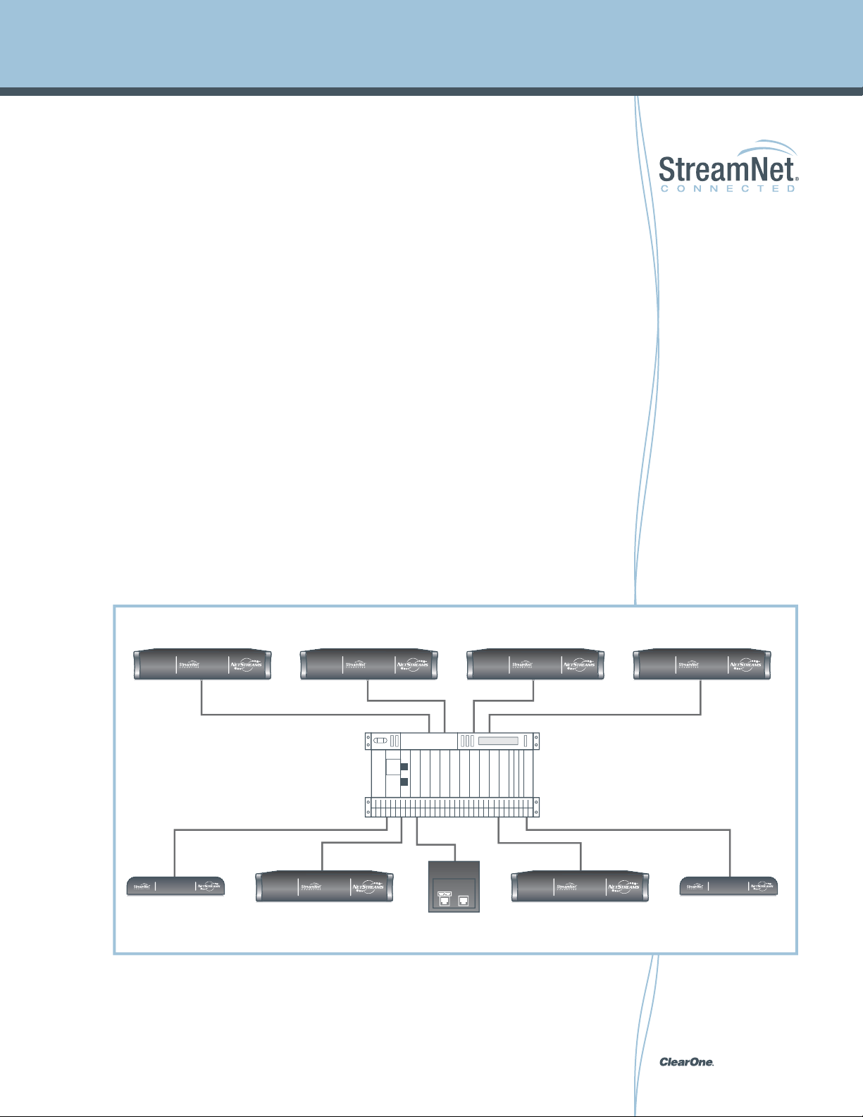
Encoders
Decoders
Ethernet Switch
pg 23 StreamNet Digital Media and System Design Reference Guide
Page 24

StreamNet Audio Technology
Automatic Synchronization of Streams (Time Sync)
A fundamental problem with using TCP/IP to distribute digital audio to multiple zones in a
home or commercial environment is synchronization of playback. Without synchronization,
audio can sputter, cut out, or have strong echo effects from zone to zone, sometimes
playing several seconds apart.
Simply incorporating a buffer to attempt to synchronize the audio is not enough. ClearOne’s
StreamNet technology provides the solution by removing the effect of network delays. This
is achieved by StreamNet assigning a “master” which is dynamically chosen to serve as the
time reference, thereby allowing all devices to share the same concept of time and stay fully
synchronized.
The sample rate is synchronized using a VCXO for low jitter. As a result, the maximum delay
between any two speakers is reduced to just 1 millisecond which is considerably below the
audible threshold. StreamNet allows audio in all zones to be synchronized when playing the
same source throughout the system, solving the problem of distributing audio over TCP/IP
packet-switched streams.
pg 24StreamNet Digital Media and System Design Reference Guide
Page 25

StreamNet Audio Technology
StreamNet is compatible with traditional audio sources because MediaLinX automatically
converts audio in real time so it may be streamed over TCP/IP for playback in any zone
including IR commands packetized for easy control of the source.
Internet Protocol (IP-Based) enables pristine audio to be delivered digitally using state-of-
the-art meshed network architecture in which each product on the network has its own IP
address and network intelligence, eliminating the need for costly matrix switches and central
controllers. In addition, audio streams are multicast to provide scalability. With StreamNet
there is virtually no limit to the number of sources or zones you can have in the system, so
no matter the size or scale of your project, ClearOne’s StreamNet system will deliver the
performance you require.
Choose Between Uncompressed, Full Bandwidth Audio and MP3. The StreamNet
Multi-Zone Audio / Video and Control system can handle a wide range of audio sources
simultaneously, from uncompressed, full bandwidth audio to MP3 songs compressed at any
sample rate.
StreamNet enables a pure digital signal all the way to the speakers. Digital provides the
highest quality audio since it represents a perfect copy of the original studio recording.
However, at the amplifier, the digital signal is converted to analog so it can be heard. A
fundamental principle in audio is the longer the speaker wire, the more compromised the
audio signal becomes, as losses can occur due to speaker wire resistance (regardless
of the gauge). Besides losses due to cable resistance, longer cables begin to exhibit a
significant reactive component of capacitance and inductance regardless of the wire gauge.
When an AV professional designs a multi-zone audio system with long cable lengths, the
signal quality is compromised even more. Using StreamNet it is now possible to maintain
the quality of the signal by allowing the power amplifiers to be located at the speaker or in
close proximity significantly reducing the length of the speaker wire required and keeping
the signal in the digital domain for as long as possible.
pg 25 StreamNet Digital Media and System Design Reference Guide
Page 26
Digital File Security and DRM
Defining DRM
DRM stands for Digital Rights Management and refers to a collection of systems used to
protect electronic media such as music, movies, images or any digital content where the
publisher wishes to ensure their data “bits” are not available to be freely swapped or shared
without proper compensation. DRM systems can vary widely but most frequently include
two primary pieces, encryption and access control.
Encryption as the name implies is designed to limit the free exchange of content so it cannot
be played outside the intended ecosystem, whereas access control is intended to limit the
number of plays or authorized devices available for playback. For example, Apple iTunes
uses a DRM system to limit the number of Apple devices iTunes files may be played on.
Digital Rights Management (DRM) is important to publishers of electronic media to ensure
they receive the appropriate revenue. By controlling the trading, protection, and access to
digital media, DRM helps publishers limit the illegal propagation of copyrighted works and
maximize revenue in the case of premium “paid” content.
The history of DRM technologies extends well before digital or electronic media existed
where copyright holders, content producers, or other financially or artistically interested
parties had certain business and legal objections to copying technologies. As early as
the player piano rolls in the 20th century copying technology represented a disruptive
technology to the live player who suddenly was no longer needed for the piano to be played.
Thus debates about the need for DRM are really not all that new. In fact we can thank a
successful outcome from the famous Sony “Betamax case” in the U.S. as paving the way for
the video tape recorder being made available for mass consumer use. Copying technology
in any form has and always will represent disruptive technology.
The advent of digital media and their associated conversion technologies, especially those
that usable on mass-market general-purpose personal computers, has vastly increased the
concerns of copyright-dependent individuals and organizations, especially within the movie
business. For this reason it is incumbent that all audio video professionals have some
understanding of DRM technologies as they can play a key role in a systems design, or in
certain equipment and cabling choices that otherwise would not be a factor.
Though certain copy protection schemes exist for analog, such as Macrovision, because
digital media files may be duplicated an unlimited number of times, with no degradation in
quality, DRM technologies are used by publishers to enforce access policies that not only
disallow copyright infringements, but also prevent lawful fair use of copyrighted works.
pg 26StreamNet Digital Media and System Design Reference Guide
Page 27

Digital File Security and DRM
DRM can even be used to implement use constraints on non-copyrighted works, examples
include the placement of DRM on certain public-domain or open-licensed e-books, or
DRM included in consumer electronic devices that time-shift both copyrighted and non-
copyrighted works.
For the AV professional the most relevant discussion around DRM is to define transfer
stream DRM as compared with DRM encryption for digital files. Example: High-bandwidth
Digital Content Protection (HDCP) compared with Microsoft PlayReady DRM.
High-bandwidth Digital Content Protection (HDCP) is a form of digital copy protection
developed by Intel Corporation and is used to prevent copying of digital audio and video
content as it moves across DisplayPort, Digital Visual Interface (DVI), High-Definition
Multimedia Interface (HDMI), Gigabit Video Interface (GVIF), or Unified Display Interface
(UDI) connections.
HDCP does not allow copying permitted by fair use laws, rather the system is meant to
stop HDCP-encrypted content from being played on devices that do not support HDCP or
have been modified to copy HDCP content. The HDCP system works as follows. Before
sending data, a transmitting device verifies that the receiver is authorized to receive it, and
if so, the transmitter then encrypts the data as it flows to the receiver. This is an example
of a transport stream DRM which is primarily what the average AV professional will come in
contact with. However, a complete understanding of digital file encryption is also required,
lest a file be attempted to play and the user presented with a dreaded, “file not authorized”
error message.
In contrast, Microsoft PlayReady DRM is one example of a system which protects digital files
and enables content services and device manufacturers to make more content available
to consumers without fear of losing control and revenue of their high value digital assets.
PlayReady fully supports domains and embedded licenses, making it simpler for consumers
to transfer and play content on a wider range of devices. Microsoft’s PlayReady technology
supports a wide range of audio and video formats, including Windows Media Audio (WMA),
Windows Media Video (WMV), Advanced Audio Coding (AAC), AAC+, enhanced AAC+,
and the H.263, and H.264 video codecs. It also moves beyond audio and video to support
games, images, and ringtones. In addition, it supports many business models for content,
including purchased downloads, subscription, rental, preview, and pay-per-view which
have now all become an essential part of premium service offerings gaining mainstream
consumer adoption.
pg 27 StreamNet Digital Media and System Design Reference Guide
Page 28

Digital File Security and DRM
Why transport stream DRM is problematic in multi-source
systems.
As is often the case with complex digital systems, particularly when DRM or digital
encryption technologies are involved, what should “just work” rarely does as promised
which is why a complete understanding of the pitfalls and challenges of multi-source and
multi-display video distribution must be understood.
To begin we need to define key elements contained within HDMI starting with the Data
Display Channel (DDC). The DDC is a two-way communications interface that sits between
the source and associated downstream repeater (or display device). The purpose of this
channel is to communicate device capability information encoded in a structure known
as Extended Display Identification Data (EDID). HDMI devices use EDID to broadcast to
receiving devices the audio and video formats supported. It should also be noted that the
DDC interface is used to set up and maintain HDCP encryption.
Adjacent to DDC is Hot Plug Detect (HPD), which broadcasts to downstream devices,
indicating its presence to the source. HPD allows each device to know when a cable has
been connected and automatically triggers authentication including EDID information about
a display to a source conveying its resolution capabilities.
Initially developed for computers and monitors, EDID is now found in most all consumer
electronic devices that support HDMI. As an example, a television may use EDID to indicate
support for the standard HD resolutions in addition to 1080p and Deep Color while another
TV may not support higher than 720p / 1080i resolution. All information regarding the audio
and video capabilities of each device is stored in its EDID.
The challenge AV professionals face in simple installations is minimal. In fact one could
argue HDMI greatly eases set-up and compatibility issues when dealing with simple
consumer systems comprising a single source and a single display. However, it is our
assumption the reader of this guide is commonly dealing with system designs of a much
more complex nature such as multi-room and multi-source, with perhaps dozens of displays
needing to be switched reliably. And for these system design applications, StreamNet was
developed.
pg 28StreamNet Digital Media and System Design Reference Guide
Page 29
Digital File Security and DRM
Because HDMI and the EDID specification were not originally conceived to be used for
multi-point installations or applications, problems may be introduced in systems typical
of what AV professionals design, install or maintain, where display devices will not show
content. Since HDMI switches are required for large multi-source and multi-display systems,
and these same switches are responsible for collecting the display’s EDID and providing
a unified version to the source, it must be noted neither the HDMI nor EDID specifications
suggest how to do this task reliably. Which is why different HDMI switches and repeaters
often behave in unpredictable ways as each manufacturer implements the standards
differently.
As illustration, consider the following system.
Your client wishes to connect a 1080p projector with a surround sound processor in the
media room or home theater, and a 720p / 1080i display in the master bedroom using the
internal speakers for audio. So the question is how should the HDMI switch combine the
EDID information so each display shows the optimum image, or in some cases shows any
image at all, and audio is correctly passed to each environment?
It is our experience that certain devices on the market solve this problem by simply copying
the EDID from the first output. However in our scenario this would mean1080p video and
surround sound audio is sent to the family room which neither supports1080p or surround
sound audio.
Another approach some HDMI switches take is to create a merged EDID that limits the
content to only what both rooms can support. Unfortunately this means our media room /
home theater is now artificially limited to 720p video and stereo audio. Once we expand this
scenario to multi-point installations with multiple rooms, source devices and displays it is
easy to see why HDMI in many systems is problematic and why many AV professionals have
“defaulted” back to analog interconnection schemes. After all with analog you are ensured
to have picture and sound on every screen in every room. Of course never mind the quality
our customers paid for is never fully realized. At least it is nearly guaranteed to work every
time or so is the rationalization of this approach. However with ClearOne’s StreamNet digital
media solution there is now a way to not only provide your customers the very best picture
and sound, and do so reliably.
pg 29 StreamNet Digital Media and System Design Reference Guide
Page 30

Digital File Security and DRM
Another complicating factor with many HDMI connected multisource / multi-display systems is HDCP encryption.
There are two parts to HDCP, which must be discussed to better understand why solving the
EDID problem alone does not guarantee reliable interconnection in advanced systems using
HDMI. The first is HDCP authentication and the second is HDCP encryption to prevent
interception during transmission. Using HDCP authentication ensures all devices receiving
®
content over the HDMI link are licensed and authorized. Only after successful authentication
may the display output audio and video streams received from the HDMI link.
Every HDMI device contains a unique ID known as KSV (Key Selection Vector), which must
be passed to the source. Devices that re-transmit HDCP content will inform the source
of all downstream connections in the system. The source must then verify each device
before it transmits content. It is this authentication process that frequently causes delays
when switching between devices as the source and display(s) must negotiate their KSV’s to
ensure content is only delivered to authorized devices.
The HDMI standard imposes a hard limit on the number of displays that can be connected.
Due to a limit in the number of KSVs available, the HDCP specification calls for only up
to 127 devices. However sources usually support considerable less than 127 and in
fact most consumer products only support ten devices at most. What this means is if a
repeater presents a source with too many KSVs, the source will cease transmitting content.
Unfortunately for the AV professional KSV limits are not an advertised feature as HDMI was
really designed for point to point communications where even ten KSVs was thought to be
“more than enough” by the manufacturer of the HDMI silicon chipsets.
When KSV values are exceeded, the viewer will not realize a problem until they try to route
an additional source to an extra display and audio / video begins to drop out inexplicably.
To make matters worse, this can occur without so much as an error message.
ClearOne’s StreamNet solution solves these problems because of the innovative application
of encoders and decoders in its architecture. Since every source in a StreamNet system is
connected to what is known as an encoder, the source is able to easily negotiate EDID and
KSV values with the connected encoder, keeping the original design intent of HDMI’s point
to point architecture intact. In the case of StreamNet decoders, these devices connect to
each display and in-turn are able to easily return the EDID and KSV information an HDMI
connected source requires. The StreamNet solution also informs the user of potential HDCP
limits and issues, for example if you try to connect to a source that has already exceeded its
KSV limit, we will instruct you on screen or on the touch panel of your options, and how to
remedy the issue. Since we store all information on each unit, we can also switch sources
very quickly, greatly improving the overall user experience.
pg 30StreamNet Digital Media and System Design Reference Guide
Page 31

HDCP Quick FAQ
Q. What is HDCP?
High-bandwidth Digital Content Protection (HDCP) is a technology developed by Digital
Content Protection, LLC (a subsidiary of Intel) to protect digital entertainment content. HDCP
has been implemented across both DVI and HDMI interfaces. The HDCP specification
provides a cost-effective and transparent method for transmitting and receiving the highest
quality digital entertainment content to DVI / HDMI-compliant digital displays.
Q. Is HDCP an option to implement in any device with an HDMI
connection?
While HDCP is optional in the HDMI specification, nearly every device intended to transmit or
receive protected content such as movies has incorporated HDCP. Manufacturers typically
do not call out HDCP support as the only devices that do not regularly include HDCP are
those not designed to transmit or receive protected content, such as consumer camcorders
and digital still cameras.
Q. If my display doesn’t have an HDCP compatible connection will I be
able to view HD DVD and Blu-ray content in high definition?
Content owners (i.e., any movie studio releasing a title on optical disc format or digital
streaming / download) decide which technologies they will require to be used to protect their
content against unauthorized copying. Movie studios fearing high-definition versions of their
titles will be pirated, almost universally use HDCP when releasing high-definition versions of
their movies. Note, there are specific requirements on HDCP usage mandated by the U.S.
Federal Communications Commission and by industry bodies in Europe and Asia. With
certain exceptions, nearly all HDMI devices on the market today include HDCP support. DVI
devices, in particular earlier versions of DVI intended for computer applications, are less
likely to support HDCP.
®
Q. Is AACS (Advanced Access Content System) an alternative to HDCP?
No, AACS is the content protection for video on Blu-ray discs and HDCP is the content
protection for all video carried over the HDMI link between an HDMI enabled source and the
display featuring an HDMI connector enabled with HDCP. AACS is a stronger replacement
for the current content protection on today’s standard-definition DVDs known as CSS or
copy scramble system. The way AACS and HDCP work in tandem is as follows. The video
player will decrypt the AACS-encrypted content coming off the disc and then send the
content over the protected HDMI link (using HDCP) to the HDTV. Of course both the source
and display must be HDCP enabled for the content to be decrypted and played back.
pg 31 StreamNet Digital Media and System Design Reference Guide
Page 32

HDCP Quick FAQ
Q. Can HDMI cables contribute to devices not working properly together?
The vast majority of image quality or interoperability issues with HDMI devices are related
to the software (firmware) used for device communication and content protection (HDCP),
and have nothing to do with the HDMI cable. These issues are often caused by the software
related to HDCP handshaking, or from devices improperly handling the device capability
information read through HDMI (EDID is incorrect). It is fairly uncommon for the cable to be
the cause of HDMI compatibility problems, generally the issues are HDCP related when a
®
source will not properly talk to a display.
Q: Is it possible for a source to connect to more sink devices (displays)
then it supports?
The answer to this question is “No”. It is not possible to achieve this unless a product is
infringing on the HDCP license due to improper implementation. This is a question of great
confusion for dealers due to a few well-known HDMI matrix switcher products not properly
implementing HDCP.
The reason this is not possible is because HDCP is a technology designed for point to point
content protection to ensure high value data transmitted digitally from a source to a display
is fully protected and not easily hijacked or stolen in route.
HDCP works by allowing every source device to accept a fixed number of keys that allow it
to support one or more display devices or “sinks” based on the number of keys the source
product supports. As an example, there are several popular cable set-top-boxes that only
support a single display device. For the A/V systems design professional and installer this
can be problematic where the client may desire the source be simultaneously displayed
on a projector and flat panel display. This is not possible if the number of display devices
exceeds the key count contained in the source.
To ensure your projects do not run afoul of HDCP licensing and implementation rules
all StreamNet products implement HDCP as specified in the Digital CP agreement. We
encourage you to not submit your company or client to legal scrutiny by using products
which do not fully or properly implement HDCP.
pg 32StreamNet Digital Media and System Design Reference Guide
Page 33

HDCP Quick FAQ
Q: How can a dealer identify products which may not properly implement
HDCP?
Unfortunately HDCP was largely designed for consumer applications where point to point
is the normal connection protocol and 1 to n signal distribution, such as found in HDMI
matrix switches, is almost nonexistent. ClearOne will never attempt to label products as
“conforming” or “nonconforming”. However, in the interest of protecting our dealers from
making an innocent mistake and selecting products which could have a disastrous legal
result, we suggest you be cautious and seek written assurances if a manufacturer claims
any of the following.
1. If a manufacturer says they have a special HDCP bypass or “lawyer” button, steer clear
as this is expressly prohibited by the HDCP robustness rules and is a clear violation of
their agreement with the Digital CP.
2. If a manufacturer claims they can support more simultaneous displays than the
connected source has keys, steer clear as the only way to do this is to work around
the KSV limitation by regenerating keys or some other trick, all of which are expressly
prohibited.
®
3. If a manufacturer claims they can support more than 127 connected devices. The
upper limit for the number of connected displays to a source is 127. Any claim beyond
this is a clear sign the manufacturer is not properly implementing HDCP.
4. If a manufacturer suggests there is a consumer implementation of HDCP and a
professional implementation which is designed for the unique requirements of matrix
switched HDMI systems. At the moment of this writing there are not two different
implementation specifications. Furthermore, the content providers are the ones who
ultimately specify how their content is protected. This means even if a professional
version where to be introduced, if the leading content providers do not authorize it their
content will fail to play over your systems.
pg 33 StreamNet Digital Media and System Design Reference Guide
Page 34

HDCP Quick FAQ
Q: What are the risks to a dealer if installing non-conforming HDCP
products?
Note: it is not the purpose of this FAQ to provide legal advise which is why ClearOne
suggests any dealer with legal questions consult an experienced Attorney on the subject of
DRM and specifically HDCP.
HDCP is licensed by the Digital Content Protection LLC (DCP) http://digital-cp.com/ which
®
means every licensee agrees to explicit terms of use and implementation. For this reason,
and given the serious view content owners rightfully take on protecting their valuable
intellectual property (movies), any licensee found to be improperly implementing the
technology will likely face legal action. Though this may not affect a dealer directly, what
could affect a dealer is if the vendors products were rendered useless because of key
revocation.
One of the attractive features of HDCP is the ability to revoke access on certain devices
should the master keys be compromised. This allows content providers a method to
prevent further content access on infringing devices, while allowing unimpeded support
on devices which have not been compromised. This means a potential risk for any dealer
selling products not conforming to HDCP fully is at some point content from certain studios
may no longer play. If this were to happen, you can imagine how difficult it would be to
explain to a client why the system works with some content but not others.
It is not ClearOne’s purpose to predict what the studios will do, but instead educate dealers
on the issues. We encourage every dealer with concerns to first not take them lightly, and
second, consult appropriate legal advice, as the facts and application around every project
will be different.
pg 34StreamNet Digital Media and System Design Reference Guide
Page 35

Public Performance Rights
Licensing bodies, why public performance matters, who is BMI, ASCAP, etc? Because most
all commercial music and video is licensed for home use only it is important to understand
when a use may become public performance so you can properly advise your client of the
unique requirements for this application. Our objective is to provide the user with general
information about licensing procedures and provide answers to the most frequently asked
questions that may be faced. Content licensing is a highly specialized area of entertainment
law and as such we recommend you consult an attorney or content licensing rights
consultant if you have any questions around this topic.
ClearOne is a responsible citizen in the copyright community and we believe wholeheartedly
in the protection of copyright. We support the philosophy that film makers, songwriters and
artists deserve to be compensated for their labors, an art which enhances the lives and
experience of every one of us.
What is “public performance”?
To perform or display a work “publicly” means two main things:
+ to perform or display it at a place open to the public or at any place where a substantial
number of persons outside of a normal circle of a family and its social acquaintances is
gathered;
+ to transmit or otherwise communicate a performance or display of the work to a place
specified by clause (1) or to the public, by means of any device or process, whether the
members of the public capable of receiving the performance or display receive it in the
same place or in separate places and at the same time or at different times.
(Title 17, U.S.C., Copyrights, Section 101, Definitions)
What does “home use only” mean?
In the case of motion pictures, including video recordings, and other audiovisual works
(music), one of the exclusive rights of the copyright owner is to perform or display the work
publicly. Unless video recordings are sold or rented with public performance rights or are
licensed for public performance, they should be considered “home use only” and should
be restricted to private showings in the home to a “normal circle of a family and its social
acquaintances.” The only exception to this is the “face-to-face teaching exemption.”
What is the “face-to-face teaching exemption”?
United States copyright law contains an exception which allows the lawful use of “home
use only” video recordings for public performance or display without the permission of
the copyright owner. Section 110 (1) of the law appears to allow the classroom use of
video programs that have not been cleared for public performance if, and only if, all of the
conditions set forth by the law are met.
pg 35 StreamNet Digital Media and System Design Reference Guide
Page 36

Public Performance Rights
Notwithstanding the provisions of section 106, the following is not an infringement of
copyright: (1) performance or display of a work by instructors or pupils in the course of face-
to-face teaching activities of a nonprofit educational institution, in a classroom or similar place
devoted to instruction, unless, in the case of a motion picture or other audiovisual work, the
performance, or the display of individual images, is given by means of a copy that was not
lawfully made under this title, and that the person responsible for the performance knew or
had reason to believe was not lawfully made;...
(Title 17, U.S.C., Copyrights, Section 110 (1), Limitations on exclusive rights: Exemption of
certain performances and displays)
Does the face-to-face teaching exemption apply to distance education?
No, the Technology, Education and Copyright Harmonization (TEACH) Act provides a more
limited right to use copyrighted material in distance education by accredited nonprofit
institutions providing certain conditions have been met. The law permits the performance of
nondramatic literary and musical works and “reasonable and limited portions” of dramatic
and audiovisual works “in an amount comparable to that which is typically displayed in
the course of a live session.” Educational materials marketed as “mediated instructional
activities transmitted via digital network” may not be used.
In order to take advantage of these exemptions there are many requirements including:
1) Access must be limited to enrolled students within class sessions; 2) Technological
protection measures must be put in place to prevent recipients from further distributing the
works; and 3) Institutions must institute copyright policies, provide information on copyright
compliance, and provide “notice to students that materials used in connection with the
course may be subject to copyright protection.”
The TEACH Act was enacted in October, 2002, and is a completely revised version of
Section 110(2) of the U.S. Copyright Act.
It should be noted that the TEACH Act does not restrict the law of fair use, which may allow
performances beyond those allowed by the TEACH Act.
Video specific Copyright information
Since there are specific uses where copyright material may be viewed in a public
performance setting it is important to consult an attorney for expert legal advise before
proceeding with your project. What follows is designed to provide an overview of copyright
issues in public performance situations.
A copyrighted video recording is a property right that gives the copyright owner of an
original work a bundle of exclusive rights. Which include the right to authorize or prohibit
reproduction, derivative works, distribution, and public performance or display of that work.
pg 36StreamNet Digital Media and System Design Reference Guide
Page 37

Public Performance Rights
Under present law, copyright exists automatically from the moment a work is fixed in a
tangible medium of expression. The work may be published or unpublished and it is not
necessary for the copyright to be registered with the Copyright Office. As of March 1, 1989,
a notice of copyright on the work is optional and its absence does not necessarily mean that
the work is in the public domain. In short the rights of copyright apply to video recordings
as well as to other works and it is best to assume all recordings are protected by copyright
(unless verified otherwise by the original creator of the creative work).
What are some of the ways to find out if a video recording has public
performance rights or home use rights?
+ Determine what rights are attached to a video recording at the time it is purchased or
acquired, and document that information. Know that the video recording is a legal copy
and know if the source of purchase or acquisition has the right to grant or convey public
performance rights or not. NOTE: It is the responsibility of the person displaying a
video recording to ensure they have legal right to do so in the situation they plan to use
it in. Do not assume showing a home use licensed movie in a church is the same as a
school or the same as a retail store. Consult an attorney if you have any questions or
concerns about whether your application could be infringing or not.
+ Look for rights information on the video label, container, or on the screen. Video
recordings with “home use only” rights usually, but not always, have statements
indicating home use. Do not assume a video recording has public performance rights
if “home use” or wording to that effect is not indicated. For example, video recordings
with public performance rights rarely have that information specifically stated.
+ Contact the copyright owner or the owner’s authorized representative for rights
information. If the rights cannot be determined, in order to avoid infringing activity, it is
advisable to assume a video recording does not have public performance rights.
When might schools or libraries consider obtaining licensing in order to
use “home use only” video recordings for public performance?
Organizations should consider purchasing a license for public performance such as when
a public library desires to show video recordings in any situation outside of the definition
of “home-use-only” or, in the case of schools, outside of the definition of the “face-to-face
teaching exemption.” As example, a public library would need public performance rights to
show a video recording to staff in an in-service workshop, to children during story hour, or
to a community group meeting. A school would need public performance rights for a video
recording to be shown for entertainment in place of recess on a rainy day, or for after-school
programs, or as a reward.
pg 37 StreamNet Digital Media and System Design Reference Guide
Page 38

Public Performance Rights
How can schools and libraries obtain a license to use home use video recordings for
public performance? One way is to contact the copyright holder directly, or the distributor
if the distributor has the authority from the copyright owner to grant licenses, to purchase
public performance rights or to request permission for a particular public performance
use. Another way to obtain a license, particularly in the case of feature films, is to contact
the licensing service representing the particular studio or title. Services vary in the types of
licensing offered and the scope of materials represented and are listed below.
Criterion Pictures USA, Inc. 8238-40 LehighMorton Grove, IL 60053-2615 1-800-890-9494 or
1-847-470-8164 Fax: 1-847-470-8194 http://www.criterionpicusa.com
Kino International Corp. 333 W. 39th Street, Ste. 503 New York, N.Y. 10018 1-800-562-3330
or 1-212-629-6880 Fax: 1-212-714-0871 Email: contact@kino.com http://www.kino.com
Milestone Film & Video P.O. Box 128Harrington Park, NJ 07640-0128 1-800-603-1104 Fax:
1-201-767-3035 Email: milefilms@gmail.com http://www.milestonefilms.com
Motion Picture Licensing Corporation (MPLC)5455 Centinela AvenueLos Angeles, CA 90066-
6970 1-800-462-8855 Fax 1-310-822-4440 Email: info@mplc.com http://www.mplc.com
Movie Licensing USAA division of Swank Motion Pictures, Inc.Schools: 10795 Watson
RoadSt. Louis, MO 63127-1012 Schools: 1-877-321-1300 Libraries: 1-888-267-2658 Other
organizations: 1-800-876-5577 Fax:1-877-876-9873 (Schools & Libraries) Email: mail@
movlic.com or mail@swank.com http://www.swank.com
Churches should contact Christian Copyright Licensing International at http://www.cvli.com/
for blanket licenses and full information on how to use copyrighted video licensed originally
for home use only in a public setting such as a religious service.
Music-Specific Copyright Information
RECORD RIGHTS
The copyrights for master recordings reproduced for use in our digital distribution
equipment are held by either the record companies or the artists themselves. The Digital
Millenium Copyright Act provides the owner of the master recording the right to receive
a royalty from any public performance of sound recordings. Because of this we wish to
ensure that all StreamNet distribution systems are not used in any way that would violate this
agreement. Any installation of our distribution system into a facility which is designated as
a public place almost always requires the payment of royalties to an appropriate licensing
body (see information on this at the end of the section). Thus it is important all public
venues, store fronts, performance stages, etc secure licenses for the reproduction rights
and performance rights in the recordings to be distributed (played) whether performed live
or reproduced electronically.
pg 38StreamNet Digital Media and System Design Reference Guide
Page 39

Public Performance Rights
PUBLISHING RIGHTS
The music publisher is the entity that holds the copyright in a song. That is, the piece of
music itself not the paper on which it is printed or the recording on which it is performed.
Anyone who wishes to record a song, perform a song or synchronize a song in a motion
picture film or television program (for example), must secure a license from the music
publisher and pay either a statutory royalty or a negotiated fee or royalty, whichever the case
may be.
PUBLIC PERFORMANCE RIGHTS
In the United States of America nearly all public performances of music are licensed through
ASCAP, BMI or SESAC. For the most part, all “professional” American songwriters belong to
one or the other of these societies. Since the societies and the music publishers derive their
rights exclusively from their affiliated writers, virtually all music publishers have companies
belonging to all three societies. Membership is these societies are open to anyone who has
had a musical composition commercially recorded and/or published.
The Copyright Act as amended in 1976 granted the copyright owner (songwriter or music
publisher as the case may be) the exclusive right to license the performance of a musical
composition in public, whether or not for profit.
CONSUMER TECHNOLOGY BILL OF RIGHTS
On October 17th, 2002 Congress introduced legislation designed to recognize the rights
of consumers to use copyright protected works, and for other purposes. Which effectively
stated that it is the Sense of the Congress that United States copyright law should not
prohibit a consumer of information or entertainment content distributed via electronic media
from engaging in the reasonable, personal, and noncommercial exercise of the six rights
described in the next section with respect to works that the consumer has legally acquired.
THE SIX CONSUMER RIGHTS
1. The right to record legally acquired video or audio for later viewing or listening (popularly
referred to as `time-shifting’).
2. The right to use legally acquired content in different places (popularly referred to as
`space-shifting’).
3. The right to archive or make backup copies of legally acquired content for use in the
event that the original copies are destroyed.
pg 39 StreamNet Digital Media and System Design Reference Guide
Page 40

Public Performance Rights
4. The right to use legally acquired content on the electronic platform or device of the
consumer’s choice.
5. The right to translate legally acquired content into comparable formats.
6. The right to use technology in order to achieve these rights.
USING TECHNOLOGY “Properly”
ClearOne is the manufacturer of equipment designed to distribute information or
entertainment content via electronic media for the sole purpose of engaging in the
reasonable, personal, and noncommercial performance of copyrighted works that the
consumer has legally acquired. ClearOne StreamNet equipment is designed and intended
for installation within a single private facility and is not designed nor intended to be installed
in a way that would provide a means to publicly perform copyrighted music without the
express prior permission of the copyright owner or their agents.
COPYRIGHT ORGANIZATIONS
If an individual or group wishes to utilize StreamNet equipment in a way which could infringe
on copyrights, they must first contact the following organizations and make arrangements to
avoid being in violation of the law.
ASCAP (American Society of Composers, Authors and Publishers) http://www.ascap.com/
Established since 1914, ASCAP has over 30,000 members and is owned, and run, by its
membership.
BMI (Broadcast Music, Inc.) http://www.bmi.com/ Established in 1940 and has a
membership of about 65,000 songwriters and publishers who are referred to as Affiliates.
BMI is owned by 500 radio and television stations
SESAC (SESAC, Inc) http://www.sesac.com/ SESAC is a privately held organization the
smallest of the three performing rights societies.
Churches should contact Christian Copyright Licensing International at http://www.ccli.
com/ for license and information on how to compensate song writers for music performed in
religious services.
pg 40StreamNet Digital Media and System Design Reference Guide
Page 41

Designing a StreamNet System, introduction to required devices
Network
StreamNet works optimally on a Gigabit packet switched Ethernet network, though
StreamNet does not require a dedicated network and peacefully coexists on any data
network provided it is properly installed and configured. To ensure optimum performance
is achieved NetStreams SwitchLinX switches auto detect 10/100/1000 Mbps speed, full/
half duplex mode and MDI/MDI-X connections. This feature provides the user a simple way
to complete the network connection with the switch. The SwitchLinX gigabit models are
certified and preconfigured for the NetStreams DigiLinX IP Audio/Video distribution system
for easy, plug and play installation, eliminating time required to configure and setup the
switch for the DigiLinX system.
Network Switch example: SwitchLinX SW1148
pg 41 StreamNet Digital Media and System Design Reference Guide
Page 42

Designing a StreamNet System, introduction to required devices
Sources
With a StreamNet Encoder literally any source with analog connectors may be made
available for distributon on the StreamNet network. StreamNet uses a distributed
architecture that allows the hardware and the processing power to be spread out across
a TCP/IP network. This leverages many of the advantages of using TCP/IP over traditional
analog systems. Traditionally, sources are located near the head end controller or additional
cabling is used remotely locate the audio/video source in a conference room or hotel suite.
MediaLinX is not constrained by traditional limitations and can be located anywhere, only
requiring a network connection. Each MediaLinX Encoder is designed to support a single
source so integrators need only to specify the exact number required and can easily add
MediaLinX as the project evolves.
MediaLinX allows for unlimited Audio/Video Sources. Using TCP/IP as a distribution method
also renders limits on the number of audio/video sources obsolete. StreamNet treats
each source as just as another device on the network and using TCP/IP multicast protocol
StreamNet easily manages the network traffic. Each MediaLinX device handles the audio
and video signal encoding, IP stream output, and source control. Beyond a MediaLinX
encoder no additional hardware is required to add a source to the system.
MediaLinX is a versatile audio encoder. Each MediaLinX encoder will accept analog
(Line level or balanced) or digital audio (S/P-DIF) signals. The audio is converted using a
Burr Brown 24-bit/96kHz analog to digital converter. The integrator can adjust the signal
output strength to insure that it is consistent with other sources on the system. Then using
StreamNet™ technology the audio is converted into an uncompressed stream of TCP/IP
packets and made available to the system.
MediaLinX is an ideal SD / HD video encoder. The MediaLinX A/V can encode, in real-time,
both SD and HD video signals into either a compressed (MotionXT) or uncompressed
stream of TCP/IP packets, depending on the speed of the network switch. Using BNC
connectors the MediaLinX accepts H Sync, V Sync, Y/G/CVBS, Pb/B/C and Pr/R signa ls
allowing a variety of source types to work with MediaLinX A/V. Converting to TCP/IP will
insure the audio and video signal does not degrade on its way to the display, even when
cable distances are hundreds or thousands of feet.
pg 42StreamNet Digital Media and System Design Reference Guide
Page 43

Designing a StreamNet System, introduction to required devices
MediaLinX offers source control. The MediaLinX A/V not only manages audio encoding,
but also handles control of the source. Each device is capable of using IR, RS-232, or IP
to control the source. RS-232 and IP protocols provide the MediaLinX A/V the capacity for
two-way control of the source allowing the MediaLinX A/V to gather metadata and feedback.
Many sources are already available that take advantage of RS-232 and IP, others can be
created using StreamNet Agents written in LUA, a readily available open-source scripting
language. By including the source control at the MediaLinX A/V, means not having to install
additional hardware for source control.
MediaLinX Encoder example: MediaLinX MLA9300-CS
pg 43 StreamNet Digital Media and System Design Reference Guide
Page 44

Designing a StreamNet System, introduction to required devices
Displays
Using a StreamNet Decoder enables IP content distributed over the StreamNet network to
be played from any audio or video system. StreamNet decoders are compatible with any
modern display device and even legacy displays.
StreamNet uses a distributed architecture which allows the hardware and the processing
power to be spread out across a TCP/IP network. This leverages many of the advantages of
using TCP/IP over traditional analog systems. Traditionally, a video signal is transmitted over
long cables runs that degrade the quality of the signal and can increase the project costs by
requiring multiple cable runs per display. Using a decentralized IP based system preserves
the HD quality of the signal and saves money by requiring only one CAT5 cable for audio,
video, and control of the display.
ViewLinX Decoders fully support compressed and uncompressed video. Video may be
distributed in both compressed and uncompressed forms. Sending video uncompressed
allows the HD quality to be preserved during distribution on a gigabit network. For
installations without a gigabit network or those with many simultaneous streams, ViewLinX
fully supports compressed formats using NetStreams proprietary MotionXT™ Video
Compression. If at a later date video quality needs change, ViewLinX can be easily re-
configured to use uncompressed video.
ViewLinX supports unlimited number of displays. Using TCP/IP as a distribution method
also renders limitations on the number of display devices obsolete. TCP/IP treats each
ViewLinX as just another device on the network. By using TCP/IP multicast protocol
StreamNet easily manages all network traffic to ensure full motion and resolution is
preserved with minimal artifacts. Additionally, StreamNet technology keeps each zone
synchronized so all zones play within 500 microseconds of each other, ensuring audio and
video is always kept in sync.
ViewLinX supports both SD and HD video decoding. Each ViewLinX Decoder converts an
IP stream (compressed or uncompressed) back into SD or HD and outputs the program
material into the appropriate signal output type. All ViewLinX Decoders can output H Sync,
Vsync, Y/G/CVBS, Pb/B/C, and Pr/R signals through BNC connectors and include an HD 15
connector for VGA signals.
ViewLinX DualDrive technology can automatically determine which signal type is being used
and route the signal to the appropriate connector. This is ideal for situations where a display
must display VGA and video signals in the case of a DVD player and PC connected such
as in a corporate board room application. Dual Drive also allows both BNC and DB-15
connectors to be connected. The ViewLinX can also be programmed to switch the displays
input based on the source signal. With a ViewLinX Decoder the AV designer has maximum
pg 44StreamNet Digital Media and System Design Reference Guide
Page 45

Designing a StreamNet System, introduction to required devices
flexibility to design the system as a user would actually use it versus create a use case
around the operating mode of the equipment.
ViewLinX Audio Decoder. In addition to outputting video all ViewLinX Decoders are capable
of outputting analog (line level and balanced) audio and digital (S/PDIF) audio.
Additional features of ViewLinX include XVO (extended Video Output) which allows the
display to plug into a 2 gang multimedia port that is connected up to 50 meters from a
ViewLinX providing a very clean installation. The multimedia port and ViewLinX output
can both be connected enabling a single ViewLinX Decoder to drive up to 3 displays with
the same source content. ViewLinX Decoders also include two macro controlled contact
closures to trigger projector screens and an input sense which can trigger a custom macro
ideal for use in museums or kiosks that require content to be started when motion is
detected, for example.
ViewLinX Decoder example: ViewLinX VL9100-CS
pg 45 StreamNet Digital Media and System Design Reference Guide
Page 46

Designing a StreamNet System, introduction to required devices
Control
With Netstreams TouchLinX control you now are in full command of your lighting, HVAC,
Security, Audio and Video from anywhere in your home, or from anywhere on the Internet.
Using StreamNet not only can all audio and video signals be distributed, but the system
fully integrates with all leading brands of audio and video components and control products.
Plus StreamNet allows you to view IP security camera’s remotely from your iOS device.
TouchLinX Control examle: TL700
pg 46StreamNet Digital Media and System Design Reference Guide
Page 47

Designing a StreamNet System, example configurations
HDMI source to destination AV flow and control scenarios
Scenario 1: HDMI source to HDMI display and StreamNet Control
HDMI SOURCE
Source controls via encoder;
IR/Serial/Contact Closure/IP
provision(s) and sense
VIEW MLAV9500
HDMI Cable
Less than 15 Meters
DVI-to-HDMI
Adapter
Display controls are conducted
via optional CEC control or with
decoder IR/Serial/IP provision(s)
and state machine via GPIO
CAT-5e+ CAT-5e+
LAN
Less than 50 kilometers
VIEW VL9300
DVI Output Decoder
VL-CEC
Less than 15 Meters
HDMI Cable
HDMI DISPLAY
Scenario 2: HDMI source to HDMI display via HDMI repeater (AVR) and StreamNet Control
Both AVR and Display controls are
Source controls via encoder;
IR/Serial/Contact Closure/IP
provision(s) and sense
conducted via optional CEC
control or with decoder
IR/Serial/IP provision(s) and state
VIEW MLAV9500
HDMI SOURCE
CAT-5e+ CAT-5e+
DVI-to-HDMI
Adapter
HDMI Cable
Less than 15 Meters
LAN
Less than 50 kilometers
HDMI Cable
Less than 15 Meters
HDMI DISPLAY
machine via GPIO
VIEW VL9300
DVI Output Decoder
VL-CEC
Less than 15 Meters
HDMI Cable
HDMI
1.X Input
HDMI
1.X Output
HDMI AVR
pg 47 StreamNet Digital Media and System Design Reference Guide
Page 48

Designing a StreamNet System, example configurations
HDMI source to destination AV flow and control scenarios
Scenario 3: HDMI source to HDMI projector via HDMI repeater (AVR) and StreamNet Control
HDMI SOURCE
Source controls via encoder;
IR/Serial/Contact Closure/IP
provision(s) and sense
VIEW MLAV9500
HDMI Cable
Less than 15 Meters
DVI-to-HDMI
Adapter
Both AVR and Display controls are
conducted via optional CEC
IR/Serial/IP provision(s) and state
CAT-5e+ CAT-5e+
LAN
Less than 50 kilometers
HDMI Cable
Less than 15 Meters
HDMI PROJECTOR
control or with decoder
machine via GPIO
VIEW VL9300
DVI Output Decoder
VL-CEC
Less than 15 Meters
HDMI Cable
HDMI
1.X Input
HDMI
1.X Output
HDMI AVR
Scenario 4: HDMI source to HDMI projector and HDMI (AVR) via HDMI repeater and StreamNet Control
Both AVR and Projector controls
Source controls via encoder;
IR/Serial/Contact Closure/IP
provision(s) and sense
are conducted via optional CEC
control or with decoder
IR/Serial/IP provision(s) and state
machine via GPIO
VIEW VL9300
DVI Output Decoder
Less than 15 Meters
HDMI
1-2
HDMI Cable
Less than 15 Meters
HDMI PROJECTOR
VL-CEC
HDMI Cable
HDMI SOURCE
VIEW MLAV9500
HDMI Cable
Less than 15 Meters
DVI-to-HDMI
Adapter
CAT-5e+ CAT-5e+
LAN
Less than 50 kilometers
HDMI
1.X Input
HDMI Cable
Less than 15 Meters
HDMI AVR
pg 48StreamNet Digital Media and System Design Reference Guide
Page 49

Designing a StreamNet System, example configurations
HDMI source to destination AV flow and control scenarios
Scenario 5: HDMI source to HDMI display and HDMI (AVR) and StreamNet Control
HDMI
SOURCE
Source controls via encoder;
IR/Serial/Contact Closure/IP
provision(s) and sense
VIEW MLAV9500
DVI-to-HDMI
Adapter
HDMI Cable
Less than 15 Meters
Projector controls are
conducted via optional
CEC control or with
decoder IR/Serial/IP
provision(s) and state
machine via GPIO
CAT-5e+ CAT-5e+
LAN
Less than 50 kilometers
VIEW VL9300
DVI Output Decoder
HDMI AVR
VL-CEC
HDMI Cable
Less than 15 Meters
VIEW VL9300
DVI Output Decoder
HDMI
1.X Input
PROJECTOR
VL-CEC
Less than 15 Meters
HDMI Cable
HDMI
AVR controls
are conducted
via optional
CEC control or
with decoder
IR/Serial/IP
provision(s)
and state
machine via
GPIO
Scenario 6: HDMI source to HDMI display and StreamNet Audio, and Control
Projector controls are
conducted via
optional CEC control
or with decoder
Source controls via encoder;
IR/Serial/Contact Closure/IP
provision(s) and sense
IR/Serial/IP
provision(s) and state
machine via GPIO
VIEW MLAV9500
HDMI
SOURCE
CAT-5e+ CAT-5e+
DVI-to-HDMI
Adapter
HDMI Cable
Less than 15 Meters
LAN
Less than 50 kilometers
VIEW VL9300
DVI Output Decoder
VL-CEC
HDMI Cable
Less than 15 Meters
SLX300
Other SpeakerLinX Amplifiers
SpeakerLinX Amplifier
connected directly to n
HDMI
PROJECTOR
speakers
pg 49 StreamNet Digital Media and System Design Reference Guide
Page 50

StreamNet Products
SpeakerLinX
Is a family of IP amplifiers designed to mount on or adjacent to a speaker or in the room
/ zone where the speakers are located. A SpeakerLinX module contains not only the IP
controlled amplifiers, but also a web server for complete control from any computing or
display device that hosts a web browser. SpeakerLi SLSL220 contantt Class-D amplifier with
the footprint the size of a credit card. By locating the amplifier right at the speaker, power
and damping losses are minimized, yielding impressive clarity and definition typically only
heard with expensive audiophile component systems.
SL254 – IP Based controller/4x25 watt Amplifier-SpeakerLinX functions
both the amplifier and a room controller. The SL254 SpeakerLinX includes
a 4 Channel, 25 watts per channel amplifier and a built-in web server that
uses an Adobe® Flash interface to control the system. The SL254 also
includes an EIM interface that allows it to use peripheral devices like the
KeyLinX, IRLinX, Audio Port and EIM enabled external amplifiers. The
SL254 provides the digital crossover for IP Ready speakers.
SL251 – IP Based controller/amplifier - an IP-Based controller/amplifier
designed to mount on or adjacent to a speaker. An Adobe® Flash®
enabled SpeakerLinX SL251 module that contains the IP-controlled
amplifiers and a web server for complete control from any computing or
display device that hosts a web browser.
SL9250 – IP Based controller/amplifier – 2 x 50 watts amplifier and controller with a built
in webserver using Adobe® Flash to control the
system. The unit comes in half rack width and
1U high enclosure. Digital crossover for IP ready
speakers. Includes balanced and single ended
outputs.
SLX300 – IP Based controller/amplifier – 2x150 watts amplifier and controller with
built-in webserver in half rack width and 1U high
enclosure included digital crossover for IP ready
speakers and balanced and single ended outputs.
SLX300
pg 50StreamNet Digital Media and System Design Reference Guide
Page 51

StreamNet Products
MediaLinX
Converts analog audio or PCM digital signals into streaming TCP/IP 24-bit/96kHz audio
streams in real time. MediaLinX also converts analog video signals into streaming TCP/IP up
to 1080p and controls legacy sources with stored IR (Infrared) commands, offering IR pass-
through and power status sensing of attached components.
MLA9101 – IP Audio encoder-Newer native IP
Based sources can output the audio directly onto
the network through the Ethernet connection.
Older legacy sources that output the audio over a line
level connection need a device to convert the audio to
an IP stream. For each legacy source the MediaLinX
encodes and prepares the audio for distribution across the DigiLinX network. In addition
to encoding, MediaLinX also provides a mechanism for one-way and two-way control,
gathering metadata and power management of the source.
TM
MLAV9300 – IP Video/audio encoder-gateway
for audio and SD/HD quality video to flow into the
DigiLinX network. For each source a MLAV9300
encodes and prepares the audio and video for
distribution across the TCP/IP netowrk. Provides a
mechanism for on way and two way control of the
source and can ensure that the source stays power on.
MLAV9500 – IP-Based A/V Encoder. DVI-D (HDMI
compatible/HDCP Compliant). Supports 1080p
and multichannel digital audio as well as analog
two channel audio in. IR input, IR/Serial RS232 output
in a 1U half rack width enclosure. Includes HDMI/DVI
adapter.
MediaLinXPro MLA4000 – IP Based 4-source
MediaLiNX component that combines digital
conversion of up to four Legacy analog or digital audio
sources and control of third party sub-systems such as
HVAC, lighting and security.
Power
MediaLinX A/V
MLAV9500-CS
pg 51 StreamNet Digital Media and System Design Reference Guide
Page 52

StreamNet Products
ViewLinX
TCP/IP Video component that provides real time decoding of an uncompressed A/V stream
from a standard Gigabit TCP/IP network into an analog or S/PDIF audio signal and a
component, composite, S-Video or VGA video signal for output to a display.
VL9100 – IP Video decoder -simplifies the design and installation of large multi-zone
include separate components for controlling the display, its all included in the ViewLinX.
audio/video distribution systems. HD and SD
quality multimedia can be distributed to virtually
unlimited number of displays by placing a
ViewLinX at each display, There is also no need to
VL9300 – IP Based video decoder – HDCP compliant output.
Included HDMI-DVI adapter and VESA mount. Optional Power over
Ethernet.
pg 52StreamNet Digital Media and System Design Reference Guide
Page 53

StreamNet Products
TouchLinX
TouchlinX is an elegant IP-based touch-screen designed to mount in a wall (standard two
gang footprint size). The 3.8-inch, 320x240 resolution color touch-screen can display the
meta-data and transport controls available for each audio source or SpeakerLinX module.
TouchLinX’s simplicity and intuitive design allows users to access their favorite songs,
artists, play lists, or stations easily and quickly. Each room can have customized bass,
treble, balance and loudness contours. TouchLinX’s functionality will expand, through
downloadable upgrades, to include zone-to-zone or whole-system intercom or messaging,
programmable alarms and more.
TL430 – 4.3 inch IP-Based in-wall touch screen controller-IP-Based in-wall LCS
touch screen features a 4.3 inch, high resolution, TFT color LCD ouch panel,
which displays the meta-data (artist, album, song, cover art) and transport
controls available for each audio/video source or SpeakerLinX module.
A/V
TALK/
MUTE
TL700 – 7.0 inch IP-Based in-wall touch screen controller-
IP-Based in-wall LCS touch screen features a 7 inch, high
resolution, TFT color LCD ouch panel, which displays the
meta-data (artist, album, song, cover art) and transport controls
available for each audio/video source or SpeakerLinX module.
TALK/
A/V
MUTE
MON DND
NS-TLA250 – Amplified Touchpad/room controller - The TouchLinX TLA250 is
ideal for zones requiring exceptional audio quality, but do not need a full color
touchscreen. The text based OLED screen provides metadata, control of the
zone, and IP intercom for the zone.
NS-KL201 – 10-button KeyLinX Keypad with IP-Intercom - The KL201 KeyLinX keypad is a
10-button single-gang in-wall keypad with intercom, microphone and monitoring capabilities
that works perfectly for applications or audio zones where basic control of audio is all that is
required.
pg 53 StreamNet Digital Media and System Design Reference Guide
Page 54

StreamNet Products
SwitchLinX
SwitchLinX is a family of IGMP (Internet Group Message Protocol) enabled, multicasting,
non-blocking Ethernet switches designed specifically for handling the high demands of
networked audio/video distribution and control products. Multiple SwitchLinX’s allow
virtually unlimited numbers of networked audio sources or other networking or control
products. The NS-SW224 SwitchLinX is designed to fit in a rack or mounted set top style,
while the NS-SW208 is small enough to be mounted anywhere.
the high demands of networked audio/video distribution products. Additional SwitchLinX
modules can be employed to expand the network video inputs.
SW1124 – 24-port IGMP (Internet Group Message
Protocol) enabled, multicasting, non-blocking Gigabit
Ethernet switches designed specifically for handling
SW1148 – 48-port IGMP (Internet Group Message
Protocol) enabled, multicasting, non-blocking
Gigabit Ethernet switche designed specifically for
handling the high demands of networked audio/video distribution products. Additional
SwitchLinX modules can be employed to expand the network video inputs.
pg 54StreamNet Digital Media and System Design Reference Guide
Page 55

AVoIP Video Encoder Feature Comparison Matrix
Encoder Features Note 1 Note 2 Note 3
Composite [YUV] Input (1) F-RCA Connector Green
Composite [YUV] Input (1) F-BNC Connector 75 Ohm Green
Composite [YUV] Pass-Through (1) F-RCA Connector Green
Composite [YUV] Pass-Through (1) F-BNC Connector 75 Ohm Green
S-Video [Y/C] Input (1) F-Mini-DIN [4 pin]
S-Video [Y/C] Input (2) F-BNC Connectors 75 Ohm Green [Y], and Red [C]
S-Video [Y/C] Pass-Through (1) F-Mini-DIN [4 pin]
S-Video [Y/C] Pass-Through (2) F-BNC Connectors 75 Ohm Green [Y], and Red [C]
Component [YPrPb] Input (3) F-RCA Connectors Green [Y], Red [Pr], & Blue [Pb]
Component [YPrPb] Input (3) F-BNC Connectors 75 Ohm Green [Y], Red [Pr], & Blue [Pb]
Component [YPrPb] Pass-Through (3) F-RCA Connectors Green [Y], Red [Pr], & Blue [Pb]
Component [YPrPb] Pass-Through (3) F-BNC Connectors 75 Ohm Green [Y], Red [Pr], & Blue [Pb]
VGA Input via DB15HD to DB15HD (1) DE-15F Connector (2) F-JackScrews
VGA Input via DB15HD to 5 BNC (5) F-BNC Connectors 75 Ohm Green [Y], Red [Pr], Blue [Pb], Grey
[H], & Black [V]
Digital Visual Interface [DVI-D] Input (1) F-DVI-D
Analog Stereo Audio Inputs (2) F-RCA Connectors Single
Ended
Analog Stereo Audio Inputs (2) Removable Screw
Down Euro blocks
S/PDIF Input (1) F-RCA Connector 75 Ohm Orange
S/PDIF Pass-Through (1) F-RCA Connector 75 Ohm Orange
Sync Pulse Sense [YUV] (1) F-RCA Connector Yellow
Sync Pulse Sense [YUV] Pass-Through (1) F-RCA Connector Yellow
Contact Closure Input (1) Removable Screw
Down Euro blocks
Contact Closure Outputs (2) Removable Screw
Down Euro blocks
Infrared / RS-232 Input Port [TSR] (1) 3.5mm Stereo TSR TX, RX, GND
Infrared / RS-232 Output Port [TSR] (1) 3.5mm Stereo TSR TX, RX, GND
Infrared / RS-232 Output Port [TSR] (1) Removable Screw
Down Euro blocks
10/100/1000 Auto Sense Ethernet Port (1) RJ45-F TIA/EIA-
DC Power Input Port (1) Removable Screw
Down Euro blocks
Front Mounted Reset Button
Front Mounted IR Status indicator
Front Mounted Infrared Reciever
Rack Mount Enclosure
Front Mounted Power LED
StreamNet DV Lossless CODEC
StreamNet MotionXT CODEC
Balanced
3.5mm (3)
position
3.5mm (2)
position
3.5mm (2)
position
3.5mm (3)
position
568-A
5.5mm (2)
position
White [Left/Mono], & Red [Right]
Green / Ground, Positive, Negative
Green / Ground, & Positive
Green / Ground, & Positive
TX, RX, GND
Green Link, Yellow Activity
Green / Ground, & Positive 10-30vDC
MLAV
300
MLAV
9300-CS
MLAV
9500-CS
pg 55 StreamNet Digital Media and System Design Reference Guide
Page 56

AVoIP Video Decoder Feature Comparison Matrix
Decoder Features Note 1 Note 2 Note 3 VL 100 VL 9100 VL 9300
Composite [YUV] Output (1) F-RCA Connector Green
Composite [YUV] Output (1) F-BNC Connector 75 Ohm Green
S-Video [Y/C] Output (1) F-Mini-DIN [4 pin]
S-Video [Y/C] Output (2) F-BNC Connectors 75 Ohm Green [Y], and Red [C]
Component [YPrPb] Output (3) F-RCA Connectors Green [Y], Red [Pr], & Blue [Pb]
Component [YPrPb] Output (3) F-BNC Connectors 75 Ohm Green [Y], Red [Pr], & Blue [Pb]
VGA Output via DB15HD to DB15HD (1) DE-15F Connector (2) F-JackScrews
VGA Output via DB15HD to 5 BNC (5) F-BNC Connectors 75 Ohm Green [Y], Red [Pr], Blue [Pb], Grey [H], &
Black [V]
XVO Output (2) RJ45-F TIA/EIA-568-A A, & B
Digital Visual Interface [DVI-D] Output (1) F-DVI-D
Analog Stereo Audio Outputs (2) F-RCA Connectors Single Ended White [Left/Mono], & Red [Right]
Analog Stereo Audio Inputs (2) F-RCA Connectors Single Ended White [Left/Mono], & Red [Right]
Analog Stereo Audio Outputs (2) Removable Screw
Down Euro blocks
Analog Stereo Audio Input/Output (1) 3.5mm Stereo TSR-F Single Ended White [Left/Mono], & Red [Right]
S/PDIF Output (1) F-RCA Connector 75 Ohm Orange
S/PDIF Output (1) F-BNC Connector 75 Ohm Orange
Sync Pulse Sense [YUV] (1) F-RCA Connector Yellow
Contact Closure Inputs (4) Removable Screw
Down Euro blocks
Contact Closure Input (1) Removable Screw
Down Euro blocks
Contact Closure Outputs (2) Removable Screw
Down Euro blocks
Contact Closure Output (1) Removable Screw
Down Euro blocks
Contact Closure Outputs (4) Removable Screw
Down Euro blocks
Infrared / RS-232 Input Port [TSR] (1) 3.5mm Stereo TSR-F TX, RX, GND
Infrared / RS-232 Output Port [TSR] (1) 3.5mm Stereo TSR-F TX, RX, GND
Infrared / RS-232 AUX Output Port [TSR] (1) Removable Screw
Down Euro blocks
10/100/1000 Auto Sense Ethernet Port (1) RJ45-F TIA/EIA-568-A Green Link, Yellow Activity
10/100 Auto Sense Ethernet Port (2) RJ45-F TIA/EIA-568-A Green Link, Yellow Activity
DC Power Input Port (1) Removable Screw
Down Euro blocks
DC Power Input Port (2) Removable Screw
Down Euro blocks
Front Mounted Reset Button
Front Mounted IR Status indicator
Front Mounted Infrared Reciever
Rack Mount Enclosure
VESA Mount Enclosure
Front Mounted Power LED VL 9300-CS LED is located on Rear
StreamNet DV Lossless CODEC
StreamNet MotionXT CODEC
Bal. 3.5mm
(3) position
3.5mm (2)
position
3.5mm (2)
position
3.5mm (2)
position
3.5mm (2)
position
3.5mm (2)
position
3.5mm (3)
position
5.5mm (2)
position
5.5mm (2)
position
Green / Ground, Positive, Negative
w/ VLCOM Green / Ground, & Positive
Green / Ground, & Positive
Green / Ground, & Positive
Green / Ground, & Positive
w/ VLCOM Green / Ground, & Positive
TX, RX, GND
Green / Ground, & Positive 10-30vDC
Red / Ground, & Positive 10-30vDC
pg 56StreamNet Digital Media and System Design Reference Guide
Page 57

View Decoder Comparison Chart
VL100 VL9100 VL9300
Composite Output Yes Yes (1 xBNC)
S-Video Output Yes Yes (2 xBNC)
Component Output Yes Yes (3 xBNC)
DB15 (VGA) Output Yes Yes (5 xBNC)
RGBHV Outputs Yes
DVI Output Yes
HDMI Output Yes (w/a)
HDCP Support Yes
Compressed Video (Motion XT Technology) 15/30/45/60Mb 15/30/45/60Mb 15/30/45/60Mb
Uncompressed Video Yes Yes
Unbalanced Audio Input Port Yes (Stereo RCA) Yes (Stereo RCA) Yes 3.5mm
Unbalanced Audio Output Port Yes (Stereo RCA) Yes (Stereo RCA) Yes 3.5mm
Balanced Audio Output Port Yes (Eruoblock)
Digital Audio Output Port Yes Yes
IR Input Port Yes Yes Yes
Display Control Port Yes Yes Yes
AUX Control Port Yes Yes
Sense Input Port Yes Yes
Contact Closures Yes Yes Yes (w/a)
Relays Yes Yes Yes (w/a)
XVO Audio/Video/Control Exp. Ports Yes (2-RJ45)
Ethernet Ports (RJ45) 10/100/1000 10/100/1000 10/100
Phoenix Connections for Power Yes Yes Yes
Mounting Options (Wall, Rack and Vesa) Wall/Rack Wall/Rack VESA/Wall
Codec Selection vs.
Primary use case or
Application
Res/.Size
StreamNet
DV
60mb 45mb 30mb 15mb 60mb 45mb 30mb 15mb
Cinema Live Action
Bandwidth Limited ANY Motion XT
Bandwidth NOT Limited ANY CODEC
Sports/News 480i-1080p
Live Sports 480i-1080p
1
1
480i-1080p
Security Camera Feed 480i 480i 480i
Movie Content HD 480i-720p 480i-720p
Hi Def Blu Ray 480i-1080p
1
480i-1080p
2
Display Size <24” ANY CODEC
Display Size 25-42” Motion XT
Display Size 42-65” StreamNet DV Motion XT
Primary Use Case/ Application
Display Size 65-120” StreamNet DV
®
®
Display Size >120” StreamNet DV
Digital Signage - Static (DB) 480i-720p Motion XT
Digital Signage - Motion 480i-1080p1StreamNet DV Motion XT
1
StreamNet DV CODEC with 1080p output requires MLAV9500 encoder and VL9500 decoder
2
StreamNet Motion XT® CODEC with 1080p output requires MLAV9500 encoder and VL9500 or VL9300 decoder
®
pg 57 StreamNet Digital Media and System Design Reference Guide
Motion XT
480i-1080p2480i-1080p
Motion XT
®
Motion XT
®
®
2
2
Motion XT
®
®
®
Motion XT
®
Page 58

Encoders vs. VL100 Decoder Compatibility Matrix
StreamNet™ DV & MotionXT™ CODEC
VL100 DHD Decoder
INPUTS
(YUV)
Compostie
(Y/C)
S-Video
(YPbPr)
Component
MLAV 300 Encoder
VGA
Composite (YOV) S-Video (Y/C)
OUTPUTS
480i-576i
YUV to YUV Auto YUV to V/C
480i-576i
Auto YUV to V/C
Format Conversion
480i-576i
Auto YPbPr to VUV
Format Conversion
480i-1080i/480p-720p
SVGA-WXGA
720p SVGA-WXGA
Format Conversion
V/C to V/C Auto V/C to YPbPr
Auto YPbPr to Y/C
Format Conversion
Auto YUV to YPbPr
Format Conversion
Format Conversion
YPbPr to YPbPr
YPbPr to YPbPr
VGA to YPbPr
Scaling
VGA S/PDIFAnalog AudioComponent (YPbPr)
720p only
YPbPr to VGA
Scaling
SVGA-WXGA
VGA to VGA
Single Ended 2-Ch. Analog Audio
PCM/Bitstream
Audio
Analog
ALL EncodersMLAV 9300-CS EncoderMLAV 9500-CS Encoder
Audio
Analog
StreamNet™ DV & MotionXT™ CODEC
RBGHVDVI-D S/PDIF
Single Ended 2-Ch. Analog Audio
PCM/Bitstream
Balanced 2-Ch. Analog Audio
480i-576i
YUV to YUV
Auto Y/C to YUV
Format Conversion
Auto YPbPr to YUV
Format Conversion
480i-1080i/480p-720p
SVGA-WXGA
480i-576i
Format Conversion
480i-1080i/480p-720p
SVGA-WXGA
Y/C to Y/C
Auto YUV to Y/C
Format Conversion
Auto YPbPr to Y/C
Format Conversion
Auto YPbPr to Y/C
Format Conversion
YPbPr to YPbPr
Auto YUV to YPbPr
Format Conversion
Auto Y/C to YPbPr
Format Conversion
VGA to YPbPr
Scaling
YPbPr to YPbPrAuto YPbPr to YUV
YPbPr to VGA Scaling
DVI to YPbPr
PCM/Bitstream/High Bit-Rate Audio
720p only
YPbPr to VGA
Scaling
720p only
YPbPr to VGA Scaling
DVI to VGA
PCM to
Analog only
PCM to
Analog only
Analog to
Digital Convertor
PCMPCM Only
PCM &
Bitstream
Analog to
Digital Convertor
PCM/Bitstream/
HBR Audio
PCM/Bitstream
KEY
Audio SignalStandard Definition SignalHigh Definition Signal
pg 58StreamNet Digital Media and System Design Reference Guide
Page 59
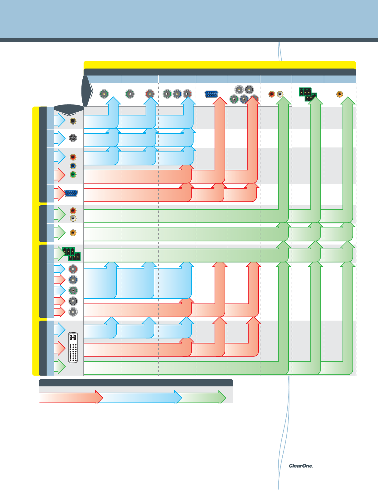
Encoders vs. VL9100 Decoder Compatibility Matrix
StreamNet™ DV & MotionXT™ CODEC
VL9100-CS HD Decoder
INPUTS
(YUV)
Compostie
(Y/C)
S-Video
(YPbPr)
Component
MLAV 300 Encoder
VGA
Composite (YOV) S-Video (Y/C)
OUTPUTS
480i-576i
YUV to YUV Auto YUV to Y/C
480i-576i
Auto Y/C to YUV
Format Conversion
480i-576i
Auto YPbPr to YUV
Format Conversion
480i-1080i/480p-720p
SVGA-WXGA
720p SVGA-WXGA
Format Conversion
Y/C to Y/C Auto Y/C to YPbPr
Auto YPbPr to Y/C
Format Conversion
Auto YUV to YPbPr
Format Conversion
Format Conversion
YPbPr to YPbPr
YPbPr to YPbPr
VGA to YPbPr
Scaling
720p
VGA Analog AudioComponent (YPbPr)
720p only
YPbPr to VGA
Scaling
SVGA-WXGA
VGA to VGA
720p only
YPbPr to RGBHV
720p only
VGA to RGBHV
PCM/Bitstream
Single Ended 2-Ch. Analog Audio
S/PDIFAnalog AudioRGBHV
PCM/Bitstream
Audio
Analog
PCM/Bitstream
ALL EncodersMLAV 9300-CS EncoderMLAV 9500-CS Encoder
Single Ended 2-Ch. Analog Audio
Audio
Analog
StreamNet™ DV & MotionXT™ CODEC
RBGHVDVI-D S/PDIF
Balanced 2-Ch. Analog Audio
480i-576i
Auto Y/C to YUV
Format Conversion
Auto YPbPr to YUV
Format Conversion
480i-1080i/480p-720p
SVGA-WXGA
480i-576i
Format Conversion
480i-1080i/480p-720p
SVGA-WXGA
PCM/Bitstream/High Bit-Rate Audio
KEY
YUV to YUV
Y/C to Y/C
Auto YUV to Y/C
Format Conversion
Auto YPbPr to Y/C
Format Conversion
Auto YPbPr to Y/C
Format Conversion
YPbPr to YPbPr
Auto YUV to YPbPr
Format Conversion
Auto Y/C to YPbPr
Format Conversion
VGA to YPbPr
Scaling
YPbPr to YPbPrAuto YPbPr to YUV
YPbPr to VGA Scaling
DVI to YPbPr
720p only
YPbPr to VGA
Scaling
720p only
YPbPr to VGA Scaling
DVI to VGA
720p only
YPbPr to RGBHV
DVI to RGBHV
PCM to
Analog only
PCM to
Analog only
PCM to
PCM
Analog only
PCM
PCM Only
PCM to
Analog only
Analog to
Digital Convertor
PCM &
PCM
Bitstream
Analog to
PCM
Digital Convertor
PCM Only
PCM/Bitstream/
HBR Audio
PCM/Bitstream
High Definition Signal
Audio SignalStandard Definition Signal
pg 59 StreamNet Digital Media and System Design Reference Guide
Page 60

Encoders vs. VL9300 Decoder Compatibility Matrix
StreamNet™ MotionXT™ CODEC
VL9300-CS HD Decoder
DVI-D Analog Audio
OUTPUTS
INPUTS
480i-576i
(YUV)
Compostie
(Y/C)
S-Video
(YPbPr)
Component
MLAV 300 Encoder
YUV to YUV
480i-576i
Auto YUV to V/C
Format Conversion
480i-576i
Auto YPbPr to VUV
Format Conversion
480i-1080i/480p720p SVGA-WXGA
VGA
Audio
Analog
ALL EncodersMLAV 9300-CS EncoderMLAV 9500-CS Encoder
Audio
Analog
StreamNet™ DV & MotionXT™ CODEC
RBGHVDVI-D S/PDIF
SVGA-WXGA
SVGA-WXGA
High Bit-Rate Audio
480i-1080i/480p
720p SVGA-WXGA
Analog to Digital PCM Single Ended 2-Ch.
Analog to Digital PCM
-
Analog Audio
PCM to Analog onlyPCM/Bitstream
Single Ended 2-Ch.
Analog Audio
480i-576i
YUV to YUV
Auto Y/C to YUV
Format Conversion
Auto YPbPr to YUV
Format Conversion
480i-1080i/
480p-720p
480i-576i
Auto YPbPr to YUV
Format Conversion
480i-1080i/
480p-1080p HDCP
PCM/Bitstream/
PCM to Analog Only
KEY
HDCP Handshaking
Audio SignalStandard Definition SignalHigh Definition Signal
pg 60StreamNet Digital Media and System Design Reference Guide
Page 61

Encoders vs. MMP-100 Decoder Compatibility Matrix
StreamNet™ DV & MotionXT™ CODEC
MMP-100 XVO Port
VGAAnalog Audio Component (YPbPr)
OUTPUTS
INPUTS
(YUV)
Compostie
(Y/C)
S-Video
480i-576i
480i-576i
Auto YUV to YPbPr
Format Conversion
Auto V/C to YPbPr
Format Conversion
(YPbPr)
Component
MLAV 300 Encoder
VGA
Audio
Analog
ALL EncodersMLAV 9300-CS EncoderMLAV 9500-CS Encoder
Audio
Analog
StreamNet™ DV & MotionXT™ CODEC
RBGHVDVI-D S/PDIF
SVGA-WXGA
480i-576i
Single Ended 2-Ch.
Analog Audio
PCM to Analog only
Single Ended 2-Ch.
Analog Audio
480i-576i
480i-1080i/
480p-720p
YPbPr to YPbPr
720p only720p only
YPbPr to YPbPr
720p only SVGA-WXGA
VGA to YPbPr
YPbPr to YPbPr
Auto YUV to YPbPr
Format Conversion
Auto Y/C to YPbPr
Format Conversion
VGA to YPbPr
Scaling
YPbPr to RGBHV
VGA to VGA
720p only
YPbPr to VGA
Scaling
480i-576i
720p only720p only
YPbPr to VGA Scaling
DVI to VGA
PCM/Bitstream/
High Bit-Rate
Audio
PCM to Analog Only
YPbPr to VGA Scaling
DVI to YPbPr
KEY
Audio SignalStandard Definition SignalHigh Definition Signal
pg 61 StreamNet Digital Media and System Design Reference Guide
Page 62
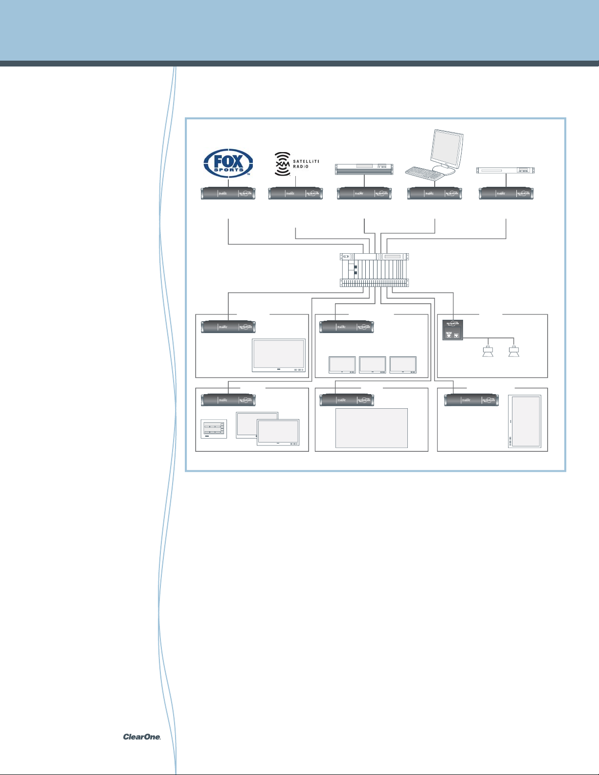
Example StreamNet System Design
Football Stadium Wiring Diagram
VIEW MLAV9300
910-225-003
Entrance Concessions Store
Boxes Field Environmental
VIEW NS-TL700
NetStreams
MediaLinX
NS-MLA4000
VIEW VL9100
910-225-011
Live Game
Big Screen
VIEW VL9100
910-225-011
Multiple
Screens
DVD/Cable/Sat PC
VIEW MLA9101
910-225-004
VIEW VL9300
910-225-012
Prices and Advertising
VIEW VL9100
910-225-011
Jumbotron
VIEW MLAV9300
910-225-003
Ethernet Switch
VIEW VL9100
910-225-011
IMPRESS IM100
Digital Signage Engine
VIEW MLAV9300
910-225-003
VIEW SL251
910-225-006
Speakers for Music
and Announcements
Artwork
Digital
Football Stadium Equipment List
Encoders:
VIEW MLAV9300 - 910-225-003
NetStreams® MediaLinX NS-MLA4000
VIEW MLA9101 - 910-225-004
Decoders:
VIEW VL9100 - 910-225-011
VIEW VL9300 - 910-225-012
Amplifiers:
VIEW SL9250 - 910-225-008
Gigabit Ethernet Switches:
VIEW NS-SW1148
User Interfaces:
VIEW NS-TL700
Power Supplies:
VIEW PL960 - 910-225-005
Digital Signage Engine:
IMPRESS IM100
pg 62StreamNet Digital Media and System Design Reference Guide
Page 63

StreamNet FAQ
1. How many zones can StreamNet distribute audio to?
2. How many sources can I connect to a StreamNet system?
3. How good is the quality of networked audio with StreamNet?
4. What cable should I use for Pre-Wiring for the StreamNet System?
5. Why don’t you power the amplifiers via CAT5 like other systems?
6. Will StreamNet integrate with other AV systems?
7. How do I program a StreamNet system?
8. I’m working on a project now, what do I need to know?
9. How do I control the music with StreamNet?
10. Can I stream music from my PC to the StreamNet system?
11. Can I listen to Internet Radio Stations on a StreamNet system?
12. How is StreamNet different from other systems that distribute
uncompressed (WAV) or MP3 files?
13. What compression ratios of MP3 does StreamNet support?
14. What is TCP/IP?
15. What does ClearOne recommend for sources?
16. Can I use a different remote control?
17. What is the Expansion Interface module (EIM) used for?
18. If I am transferring files or browsing the Web, will it interfere with the
music?
19. How far can I run the wires for StreamNet?
20. Can I program the music to turn on and off and specific times?
21. Why should I locate the amplifiers at the speakers?
22. Can I mount the amplifiers in another location?
23. How loud will the music play?
24. Does StreamNet distribute digital (SP/DIF) audio?
25. Can I use SpeakerLinX with any speaker?
pg 63 StreamNet Digital Media and System Design Reference Guide
Page 64

StreamNet FAQ
1. How many zones can StreamNet
distribute audio to?
A StreamNet system can be almost
infinitely expan ded, just like a computer
network (the distribution is based on
computer network technology). There is
currently a hypothetical limit of around
1,800,000 rooms, but we’re working on
that…
2. How many sources can I connect
to a StreamNet system?
Essentially, as many as you want. Connect
supported Audio Request® music servers
directly to SpeakerLinX using the Ethernet
connection. Legacy Audio Sources
(such as CD, Cassette player) each can
be connected to the network using the
MediaLinX IP-based Media Converter/
Controller via analog or coaxial digital
connection.
3. How good is the quality of
networked audio with StreamNet?
How good is your source? StreamNet
is designed to never degrade the sound
quality. Since the network is digital, the
audio signal is always kept intact, full
bandwidth and resolution. StreamNet
devices also incorporates Burr-Brown®
96 kHz / 24-bit D/A and A/D converters to
maximize sound quality. StreamNet will
perfectly reproduce the source, even from
hundreds of feet away!
4. What cable should I use for PreWiring for the StreamNet System?
The StreamNet system utilizes Siamese
Ethernet + 14 or 16 gauge speaker wire
-- the new industry standard for audio
distribution. This allows for many different
types of installations and applications.
Ethernet insures maximum bandwidth
for audio distribution and the 14 or 16
gauge speaker wire is used for the power
connection.
5. Why don’t you power the amplifiers
via CAT5 like other systems?
We found we could not get small amplifiers
to run properly off the limited current
capacity a CAT5 cable and RJ45 connector
is able to support. The amplifiers in the
StreamNet system are supplied 28 volts
from dedicated power supplies via thicker
14 or 16 gauge “speaker wire”. This
means we can have a much more powerful
amplifier resulting in fuller, richer sounding
audio. StreamNet is a professional audio
distribution system with wide frequency,
SPL and extended headroom support.
6. Will StreamNet integrate with other
AV systems?
There are several ways to integrate
StreamNet with a wide variety of home
subsystems (lighting, security, telephones,
doorbells, air conditioning etc). Most
advanced systems are migrating to IP
networked control. StreamNet will also
integrate via RS-232 commands sent over
Ethernet, and IR commands.
pg 64StreamNet Digital Media and System Design Reference Guide
Page 65

StreamNet FAQ
7. How do I program a StreamNet
system?
Normally a StreamNet system is installed
and setup by an Authorized trained
professional installer. A Dealer setup
program that runs on a standard web
browser is used to configure the system
and IR.
8. I’m working on a project now,
what do I need to know?
The wiring infrastructure is quite simple.
Ideally run CAT5e plus a 4 conductor
speaker wire from the location where
your sources will be out to each room.
Drop a service loop in a location where
you would install a control keypad
(typically near a door entrance or by
a desk) and then continue the wire
(including the CAT5e) up to the speaker
locations. If you anticipate installing
an Audio Port, which can export the
networked audio into a local system,
adding a sub woofer, or inputting a local
source in the system, the run another
CAT5e from the control keypad to that
source.
9. How do I control the music with
StreamNet?
There are many ways to select and
control what you listen to in a StreamNet
system. TouchLinX keypad, which offer a
3.8 color LCD and touch-screen, mount
in the wall, at any desired location.
These keypads generate a rich user
interface and can control the audio and
sources in any room. The system can
also be controlled via KeyLinX button
keypads, a wireless equipped PDA, a
computer, or any web enabled device.
10. Can I stream music from my PC
to the StreamNet system?
Yes, but the meta-data (song title, track
title, artist name) available on the PC can
not be distributed at this time. This will
change in the near future when ClearOne
makes available software that will allow
your PC to stream its music, meta-data
and control functions.
11. Can I listen to Internet Radio
Stations on a StreamNet system?
Yes, but the Internet Radio source must
be IR controlled and you must use a
MediaLinX to proxy this source onto
the network. This will change in the
future when ClearOne makes available
a networked Internet Radio, which in
addition to streaming its audio, it will also
stream its meta-data, and control.
12. How is StreamNet different from
other systems that distribute
uncompressed (WAV) or MP3
files?
While StreamNet makes it very easy to
listen to MP3 audio files, its capabilities
are not nearly that limited. StreamNet
gives you access to far more then just
MP3 files. The system can distribute
any source, including CD’s, AM, FM, TV
sound, even your old 8 track tapes! All
of your music is easily accessed and
controlled. Systems that are designed
primarily to distribute MP3 files do not
allow you to listen to you CD’s, without a
CD player in your room and the hassle of
finding the CD wherever in the house it
pg 65 StreamNet Digital Media and System Design Reference Guide
Page 66

StreamNet FAQ
may be. StreamNet also offers far superior
sound quality. Unlike MP3 files, which
compress the sound by literally discarding
70% of the musical information, StreamNet
can distribute your music collection in full,
uncompressed fidelity. Should you decide
to listen to MP3 files, StreamNet offers
complete control over your music library
so that you can browse and sort by artist,
album genre or song title. And StreamNet
allows you to play different music in each
room or the same music in all rooms,
simultaneously; beautifully synchronized
(other systems simply cannot perform this
important function).
13. What compression ratios of MP3
does StreamNet support?
The StreamNet system supports the
following compression ratios of MP3
files, VBR (variable bit rate) 64 to 320
kbps. Support for additional Codec’s
will be added in the future, and may be
downloaded directly.
14. What is TCP/IP?
TCP/IP stands for Transmission Control
Protocol/Internet Protocol. This is the basic
communication language for computers
on the Internet (also on intranets and
extranets).
15. What does ClearOne recommend
for sources?
You can use any sources you wish, analog,
digital or networked. StreamNet can
handle everything from the newest hard
disc based audio servers to old 8 track
players.
16. Can I use a different remote
control?
There are many different types of remote
control options. Any learning remote can
control sources on a StreamNet system.
You can also use any device equipped with
a web browser.
17. What is the Expansion Interface
module (EIM) used for?
There are many different uses for it. You
can use analog wall mounted input plates,
Bluetooth Digital Interfaces, External
amplifiers, Keypads, and more.
18. If I am transferring files or
browsing the Web, will it interfere
with the music?
No . The StreamNet system uses a very
sophisticated network technology to ensure
complete integrity of all StreamNet and
data traffic on the network is maintained.
19. How far can I run the wires for
StreamNet?
For maximum quality and reliability,
ClearOne always recommends adherence
to the guidelines for networking practices
of the IEEE 802.3 standard. Nominally that
means runs up to 100 meters are fine,
beyond that, a repeater or other devices
can be installed to extend the range to
whatever you require. For very long runs,
you may wish to use a local power supply.
pg 66StreamNet Digital Media and System Design Reference Guide
Page 67

StreamNet FAQ
20. Can I program the music to
turn on and off and specific
times?
Not yet, but in the near future, you
will be able to this. Since the firmware
for the system can be upgraded via
the internet. Users will be able to set
wake alarms and sleep alarms for
each room via their TouchLinX touch-
screens.
21. Why should I locate the
amplifiers at the speakers?
There are lots of very significant
advantages to locating the amplifiers
as close to the speaker as possible.
The foremost advantage is that it
helps the system sound great. The
closer the amplifier is to the speaker,
the better the power transfer and
control. This design also protects
your investment in your entertainment
system. Many other systems place
all the amplifiers in on unit, where
they may generate a tremendous
amount of heat, dramatically reducing
the lifespan of the other electronics.
Additionally, in the unlikely event of
an amplifier failure, only one room is
disturbed and a replacement can be
simply plugged in. If all the amplifiers
are in one unit, losing just one channel
means the entire system must be
shut down until the amplifier can be
repaired and returned. This typically
takes weeks. ClearOne’ design would
have you back up and running in
minutes (and all the rest of the system
would operate perfectly the entire time.
22. Can I mount the amplifiers in
another location?
Yes. SpeakerLinX intelligent amplifier
modules can be mounted to a truss
or a beam, inside a wall (decorative
cover plate sold separately), or rack
mounted (up to 4 on each rack mount
plate (also sold separately).
23. How loud will the music play?
That will depend on the speaker and
the room, but it’s safe to say loud
enough for just about anything. Having
a powerful amplifier located right at
the speaker maximizes the efficiency
of the amplifier/speaker combination.
And if you want even more power,
an additional amplifier (or amplified
subwoofer) can be easily added to the
room where the speakers are located.
24. Does StreamNet distribute
digital (SP/DIF) audio?
StreamNet can distribute analog,
digital or compressed (MP3, WMA)
files with no loss. The audio is
transmitted via TCP/IP, overcoming the
normal limitations of analog or digital
audio distribution.
25. Can I use SpeakerLinX with any
speaker?
Yes you can. Your system designer can
help select the proper SpeakerLinX
module for optimum performance.
SpeakerLinX modules can be mounted
on or near the speaker, in the room
or even in the main equipment rack.
Wherever it is located, the module will turn
your speaker into an IP enabled device.
pg 67 StreamNet Digital Media and System Design Reference Guide
Page 68

Solving Digital Media Related AV Problems
®
Why AV designers must “conquer” HDMI
Hollywood studios and major television networks require that devices supporting
(transmitting) HD video do so only to protected outputs that use HDCP. The Blu-ray Disc
Association (BDA) delayed activation of the image constraint token (content protection flag)
to help minimize transition issues. However, after December 31, 2010 all new BD players
must limit analog video output of Blu-ray disc content to interlaced standard definition
(480i). And in fact, the BDA has set December 31, 2013 as the expiration date for analog
video on a BD player, stating that no player passing “Decrypted AACS Content” to analog
video outputs may be manufactured or sold after this date. This means future HD movies
will not be viewable at HD resolutions over analog or other unprotected interfaces, making
any AV distribution system designed solely around analog or unprotected signals suddenly
obsolete. Furthermore it is important to note that a similar situation exists with premium
cable and satellite TV, in which the Motion Picture Association of America (MPAA) is
petitioning the FCC to restrict HD transmission to protected outputs.
Unfortunately for the modern AV systems designer, HDMI can be challenging as it was
never intended for multi-point distribution applications making system designs all that
more challenging in all but the smallest of applications. However, for those designers
using StreamNet products and solutions, common HDMI problems and issues are all but
eliminated.
pg 68StreamNet Digital Media and System Design Reference Guide
Page 69

Solving Digital Media Related AV Problems
HDCP Keys
HDMI with HDCP was created as a consumer technology to enable point to point secure
transfer or transmission of high quality digital content such as HD, and it was never intended
to be used in large multi-source and multi-display (zone) applications required by modern
residential or commercial AV projects. This means, too many devices in a signal path is
destined to create problems with the display of audio and video content.
HDMI source devices all have a limit to the number of downstream devices they support.
This limit is determined by the number of available HDCP keys in the device. All HDMI
sources that utilize HDCP limit the number of devices which may be connected at one
time. For this reason an important aspect of HDCP for all AV designers and installation
professionals is the use of “keys” which HDCP utilizes to manage handshaking between
devices.
The HDCP specification states the maximum depth (number) of devices between source
and display is six (6). This means connecting too many displays or video devices will cause
the source to stop outputting a signal without warning in most HDMI switching systems.
However, a unique feature of StreamNet is that the system actually provides user guidance
to the user of options available in an extended condition and provides choices, compared to
simply shutting off the stream without warning or explanation as most other HDMI switching
or digital transmission solutions would do.
®
pg 69 StreamNet Digital Media and System Design Reference Guide
Page 70

Solving Digital Media Related AV Problems
®
HDCP Keys continued
Following is a more technical description of HDCP, beginning with two primary parts:
1. Authentication
2. Encryption
Using HDCP, authentication ensures all HDMI connected devices receive only content that is
licensed and authorized. Only after successful authentication will the display device output a
stream.
In a multi-point AV system, HDCP encrypts each segment of an AV transmission, and HDCP
authenticates every device via the source. Devices that re-transmit HDCP content inform
the source of all the downstream connections. This means every HDCP device has a unique
ID, known as a Key Selection Vector or KSV. The KSV must be passed to the source, which
then verifies every device before beginning to transmit content. In large systems, it is this
authentication process that frequently creates extended switch times when a new source is
selected. With StreamNet, because of its persistent architecture and method of handling
keys, switch time is nearly eliminated leading to a vastly improved user experience.
It is important to note that all sources have a predetermined limit on the number of display’s
which may be connected. This limit is caused by the number of KSV’s the source is able to
accept. Though HDCP allows for up to 127 devices, sources generally support as few as ten
and we have even found some which only support a single display.
The reason this can be a problem is when a repeater presents a source with too many
KSV’s, the source will stop transmitting content with no explanation. For this reason
installers must be aware of KSV limits in any HDMI installation involving more than one
display. We highly suggest testing devices in the field before completing a system design to
ensure your intended system results and performance may be achieved.
pg 70StreamNet Digital Media and System Design Reference Guide
Page 71

Solving Digital Media Related AV Problems
Manufacturer Model HDCP Key Count Chart
Manufacturer Device Type Model Name HDCP Keys
Advanced Digital
Broadcast
Anchor Bay Digital Video
Apple Digital Media Player Apple TV (gen 1) 16
Crestron Digital Media Player ADMS 16
Denon BD Player BDP-1610 16
DirecTV Satellite STB HR21 N/A
Dish Network Satellite STB ViP-211 16
DVICO Digital Media Player TViX HD M-6500A none
EchoStar Europe Satellite STB Vi P211 16
Echostar STB Satellite STB VIP-222 16
Enseo Tuner HD2000 16
Insignia BD Player NS-2BRDVD 13
Integra BD Player DBS 30.1 3
Integra BD Player DBS 6.9 3
LG BD Player BD-270 10
LG BD Player LG-BD370 10
LG BD Player LG-BD390 16
LG BD Player Super Multi-Blue 16
Marantz BD Player BD-7003 3
Marantz BD Player BD-7004 3
Marantz BD Player DV4001 9
Microsoft Game Console XBOX 360 16
Motorola Cable STB DCH-3416 1
Motorola Cable STB DCT-3200 1
Motorola Cable STB DCT-3412 1
Motorola Cable STB DCT-6412 1
Motorola Cable STB DCT-6416 1
Motorola Cable STB VIP 1200 16
Panasonic BD Player DMP-BD30 3
Panasonic BD Player DMP-BD35 3
Panasonic BD Player DMP-BD60 3
Panasonic BD Player DMP-BD80 3
Philips BD Player BDP 7200 16
Philips DVD Player DVP5990/12 9
Pioneer BD Player BD-LX80 16
Pioneer BD Player BD-LX91 16
Pioneer BD Player BDP-6000 16
Pioneer Elite BD Player BDP-05FD 16
Roku Digital Media Player N1000 16
IPTV STB ADB-3800W 16
Edge 101 8
Processor
Manufacturer Device Type Model Name HDCP Keys
Samsung BD Player BD-P1000 16
Samsung BD Player BD-P1500 7
Samsung BD Player BD-P-1600 7
Samsung BD Player BD-P-3600 16
Samsung BD Player BD-T3600 16
Samsung BD Player BD-UP5000 10
Samsung BD Player DBD-P1500 16
Scientific Atlanta Cable STB Explorer 4250HD 16
Scientific Atlanta Cable STB Explorer 8300HD 16
Sharp BD Player BD-HP20 16
Sharp BD Player BD-HP21U 3
Sharp BD Player BD-HP22 3
Sharp BD Player BD-HP50 3
Sky Satellite STB Sky HD 16
Sony BD Player BDP-S2000ES 16
Sony BD Player BDPS301 16
Sony BD Player BDP-S350 8
Sony BD Player BDP-S360 8
Sony BD Player BDP-S5000ES 16
Sony BD Player BDP-S550 10
Sony BD Player BDZ-X100 8
Sony BD Player DVD-P DPX - 2380 9
Sony DVD Player DVP-NS71HP 16
Sony DVD Player DVP-NS72HP 9
Sony Game Console PS3 16
TiVoHD DVR STB TiVoHD 16
Toshiba HD-DVD Player HD-A20 10
Toshiba HD-DVD Player HD-A3 16
Toshiba HD-DVD Player HD-A30 16
Toshiba HD-DVD Player HD-A35 16
Toshiba HD-DVD Player HD-D3 16
Toshiba HD-DVD Player HD-E1 10
Vudu Digital Media Player VUDUBX100 16
Western Digital Digital Media Player WDTV N/A
This information has been deemed accurate based on HDCP key data
found on chip set data sheets and other Internet sources including
StreamNet receivers which capture and log all HDCP information of the
connected source unit(s).
pg 71 StreamNet Digital Media and System Design Reference Guide
Page 72

Solving Digital Media Related AV Problems
®
EDID and DDC
EDID stands for Extended Display Information Data. This is the data contained on each DVI
display or HDMI sink and there may be as many as one EDID per DVI or HDMI input. The
source device checks the display’s DVI or HDMI port for the presence of an EDID prom and
uses the information to optimize the output video and / or audio format. All sink devices
compliant to the DVI or HDMI specification must implement EDID.
EDID was formed as a standard to help PC monitors report their capabilities whereas
E-EDID is an extension of the EDID specification used traditionally by consumer electronic
devices to illustrate more advanced features. For example, PC monitors generally do not
support audio, so a traditional EDID structure would not account for this, whereas an E-EDID
would.
Before we discuss the role of EDID it’s important to understand the role of the DDC (Display
Data Channel) in the HDMI specification. In a video system, the vast majority of information
flow occurs from a source to a sink (display) where the video and / or audio travels. DDC
provides a back channel from the sink to the source to indicate events like hot-plug when
a new device is suddenly connected to the system or HDMI chain. The sink communicates
its display output capabilities back to the originating source device using DDC. Without this
feature, devices like DVD players would have to guess at what video / audio formats any
given display is optimized for.
An EDID PROM is used only in sink devices where this PROM sits on the DDC channel and
uses a 2-wire I2C bus (part of the DDC specification from www.vesa.org) to communicate
from the sink to the source. The EDID PROM contains information about the sink it resides
in. Its job is to communicate the preferred (or supported) video and audio formats and
resolutions to the originating source.
As an example, when a DVD player is powered on, it reads the EDID from an attached
HDTV. The HDTV will have in its EDID data pertaining to the size and type of display along
with native resolution, all supported resolutions including video connection capabilities, and
audio support. A connected source would compare this information with what it can put
out of its HDMI port, and automatically set itself up to send the best video and audio format
appropriate for the display.
pg 72StreamNet Digital Media and System Design Reference Guide
Page 73

Solving Digital Media Related AV Problems
Repeaters
One limitation of HDMI is that traditional cables are general only certified for use up to
10 meters in length. However, HDMI technology has been designed to allow standard
copper cable construction at longer lengths but requires the use of a repeater to extend
beyond 10 meters. In order to allow cable manufacturers to improve their products through
the use of new technologies, HDMI specifies the required performance of a cable but not
maximum cable length. NOTE: It is not only the cable that factors into how long a cable can
successfully carry an HDMI signal but also the receiver chip inside the display which also
plays a factor. Receiver chips that include cable equalization are able to compensate for
weaker signals, thereby extending the potential length of any cable used with that device.
It is important to be aware of both active and passive solutions when it comes to HDMI
cables. Whereas a repeater by definition must be active and therefore power supplied to
the device in some manner. Any HDMI device that has active electronics should have a
provision for external power in order to be compliant. Some active devices, such as actively
powered HDMI cables or in-line signal extender boxes, will by default attempt to power their
electronics by taking power from the 5V line (+5V power) available on the HDMI connector.
The HDMI specification requires all source devices to provide at least 55mA (milliamps) on
the 5V line for the purpose of reading the EDID of a display.
®
While 55mA is not enough current to operate most HDMI accessory devices (which
typically require about 100 to 150mA), most source devices on the market today provide
significantly more current on the 5V line than the HDMI specification requires. As a result,
the vast majority of accessory devices can operate when interfaced with a source device
that provides more than the required current (i.e. over 100-150mA) on the 5V line. However,
it should never be assumed that the source device will provide enough power, and
manufacturers should make a provision for their powered HDMI accessory devices to obtain
external power.
For the AV systems installer and designer, what this means is that failure of video output
when a Repeater is used can often be attributed to a simple lack of adequate power. Just
because a device says it doesn’t need an external power supply, it is advisable to not use
it and select one where you can be assured the product will always have adequate power
regardless of the source that is connected.
pg 73 StreamNet Digital Media and System Design Reference Guide
Page 74

Solving Digital Media Related AV Problems
®
The truth about matrix switches and HDCP
Many HDMI switches are nothing more than “muxers” providing digital cross connection
between multiple sets of HDMI inputs and HDMI outputs. For this reason, issues with HDCP
key exchange and EDID / DDC channel integrity where displays will suddenly stop working
or intermittent blanking occurs. It is not ClearOne’s purpose to identify products that do not
comply with HDCP licensing rules, however it is our objective to help dealers not fall into the
marketing hype of companies with potentially infringing products.
It has been reported that several well known manufacturers are making claims both public
and private about capabilities of their products which should the claims be true are in clear
violation of the Digital CP (HDCP) licensing agreement. We suggest if you have specific
applications or questions around HDCP that you speak with the vendor company and
consult a DRM licensing Attorney. To help navigate the marketing hype of these potentially
infringing vendors, dealers should pay close attention to any vendor making the following
claims.
1. Claim to have a special HDCP bypass or “lawyer” button.
2. Claim they can support more simultaneous displays than the connected source
supports. We suggest you consult ClearOne’s key count chart found in this guide.
3. Claim they can support more than 127 connected display devices.
4. Claim there is a consumer implementation of HDCP and a professional implementation
designed for the unique requirements of matrix switched HDMI systems.
5. Claim they have any “special” agreement with content providers.
6. Claim content providers don’t care because the professional and custom electronics
A/V channels are so small.
7. Claim they can sell you additional keys to support more devices.
pg 74StreamNet Digital Media and System Design Reference Guide
Page 75

Solving Digital Media Related AV Problems
Troubleshooting matrix switch connectivity problems
When troubleshooting display problems with a matrix switch begin by taking the source to
within a standard HDMI cable length of the display (less than 10 meters) to test if syncing
between the source and display is possible.
Assuming the test is successful and you obtain a picture, work backwards from the display,
carefully accounting for every device in the signal chain. Simply go to the nearest upstream
device from the display and plug the source in to see if a picture may be obtained. By
repeating this process you can quickly determine where the signal is failing to pass.
Once the device not passing the video signal is identified, try physically switching inputs as
it is not always the case that HDMI Input 1 travels through the same silicon path as HDMI
Input 3, for example. Though better quality displays will offer the signal path regardless
of Input, we have seen examples where varying silicon parts are used which can lead to
sporadic performance across different displays.
Also, do not assume all HDMI cables are created equal. Furthermore, we encourage you
not to assume the more expensive a cable, the better it is! There are some well known
cases where the technical performance of a lower cost cable was actually better than the
more expensive interconnect. This is not to say there is no performance advantage to
higher end cables. As always don’t buy based on marketing hype, do your homework. And
when you find a good quality reliable cable, keep using them. Cables matter in every point
of an A/V system, but they really matter when dealing with HDMI.
®
One of the major advantages to StreamNet is the elimination of an HDMI matrix switcher,
which reduces overall system cost while improving system performance and reliability.
pg 75 StreamNet Digital Media and System Design Reference Guide
Page 76

Solving Digital Media Related AV Problems
®
How StreamNet reduces HDMI switching time and improves
system stability
Sync time between an HDMI connected source and display is typically around 2 seconds.
This can cause confusion with any user who selects a program source, fails to see a picture
and begins making other source selections. Source switching time is compounded in large
systems as every additional matrix switch, video processor or other HDMI connected device
in the chain increases the overall handshake and key exchange time.
Since StreamNet is not a matrix switched topology, switching between sources occurs
nearly instantaneously as the source is always in sync with the StreamNet encoder, and the
display is always in sync with the StreamNet decoder.
This means in practical application, a user on a StreamNet system experiences the speed
and reliability of analog, but with the picture quality, resolution and performance of digital.
StreamNet system architecture is point to point, exactly how the HDMI interface was
conceived to operate. With StreamNet, system stability is improved due to the elimination of
multiple levels of devices leading to fewer key exchanges, improving the odds of a display
not blanking.
pg 76StreamNet Digital Media and System Design Reference Guide
Page 77

pg 77 StreamNet Digital Media and System Design Reference Guide
Page 78

Glossary
Video Resolutions
Interlaced Scanning
Interlaced scanning displays (TV’s) show oddnumbered lines in succession, followed by the
remaining even-numbered lines. This method is
more prone to artifacts and was required for older
cathode ray tube (CRT) video technology but is not
needed for modern digital TV’s (DTV). However,
much source material is still formatted in an
interlaced format so all DTV’s will display interlaced
video.
480i
480i where the “i” refers to the term interlaced is a
form of standard definition digital television (SDTV).
All analog and digital video outputs support this
lowest level of video resolution.
Progressive Scan
Progressive scanning is a way of displaying images
and video where all lines of every frame are drawn
in sequence so the eye sees the entire picture
at once as compared to interlaced video where
the odd lines are alternated with even. For video
with scenes of fast motion, progressive scanning
provides the best visual presentation with the
absence of visual artifacts such as interline twitter.
Other benefits include better quality scaling to
higher resolutions since scaling works with full
frames.
480p
480p where the “p” refers to the term “progressive
scan”, a form of standard definition digital
television (SDTV) comparable to VGA computer
displays. For reference, native resolution of DVD
is 480p. However that resolution can be seen only
if a DVD player outputs a progressive scan signal
and the Digital TV accepts a progressive scan or
component video input. It is also known as EDTV.
720p
720p where the “p” refers to the term progressive
scan is one of two currently used formats
designated as high definition television in the ATSC
DTV standard. This technology comprises 720
vertical pixels and 1,280 horizontal pixels. 720p is
not inferior to 1080i though 720p has fewer lines
of resolution it has the advantage of providing
progressive scanning and a constant vertical
resolution of 720 lines, making it ideally suited to
handle video with a high degree of motion.
1080i
HDTV standard that specifies an interlaced
resolution of 1920 x 1080. Only analog component
video and digital video outputs such as HDMI are
able to support full 1080i video.
1080p
1080p is the highest resolution in the HDTV
standard and refers to an image size that is
1920x1080, it is also often called progressive
scan. Only digital video outputs such as HDMI are
capable of supporting 1080p video. Be sure to
check with your source and display manufacturers
to ensure the HDMI connectors on your equipment
support 1080p as not all do.
Deep Color
Color depth standard associated with the HDMI
1.3 standard. Deep Color supports 10-bit, 12-bit
and 16-bit color depths, an increase from 8-bit.
Benefits of increased color bit depth include finer
gradations between different shades of the same
color meaning the viewer will experience smoother
gradients and reduced color banding. Deep Color
also enables the potential for a supported TV to
display billions of colors. To view this improvement
the entire video production chain must support
Deep Color from the camera, editing software,
video format, player, and display.
Video Scaling
In DTV because of the myriad of formats and
resolutions possible, scaling is the process a
display device (TV) must use to map the source to
the actual capabilities of the display. For example,
the conversion from a higher resolution input signal
to a lower one.
Aspect Ratio
The ratio of width to height in a video display
window. Traditional U.S. TV broadcasts and
computer monitors featured a 4 by 3 aspect ratio
whereas HDTV broadcasts typically feature a 16 by
9 width to height ratio.
16:9
Sometimes expressed as 16 by 9, 16 x 9 or 16:9
(also known as 1.78:1 in the film world). 16 by 9 is
the standard DTV widescreen television standard
which is 16 units wide by nine units high, as
compared to a standard TV aspect ratio of 4 by 3.
4:3
Standard NTSC TV screen size measured by four
units wide by three units high and often expressed
as 4 x 3 or 4 by 3. In the film world 4:3 is also
expressed as 1.33:1.
Anamorphic
Adopted from the film technique of shooting a
widescreen image on a square 35mm frame,
anamorphic is the process of compressing
widescreen images to fit into the squarer
standard 4:3 television signal. The images are
then expanded for viewing in their original format
on a widescreen display device. Widescreen or
letterboxed DVDs that are not anamorphic have
less detail when projected on a widescreen monitor
because fewer lines are used to draw the image on
the display and thus full resolution is not achieved.
A non-anamorphic widescreen DVD is designed to
be shown letter boxed on a standard “square” TV
but appears with a black box all around the image
when shown on a larger 16:9 widescreen TV. To
fill a 16:9 screen, a non-anamorphic DVD has to
be stretched, resulting in loss of resolution and
detail. Whereas an anamorphic DVD that has been
enhanced for 16:9 displays delivers 33 percent
more resolution than regular letterboxed transfers.
pg 78StreamNet Digital Media and System Design Reference Guide
Page 79

Glossary
Signal types and video
formats
Component video
The electrical elements that comprise a video
signal, consisting of luminance and two separate
chrominance signals. These are expressed as
either Y R-Y B-Y or Y Pb Pr. Component video is
the highest quality analog format for HD video up
to 1080i.
DisplayPort
A digital display interface proposed by the Video
Electronics Standards Association (VESA) that
defines a new license-free, royalty-free, digital
audio and video interconnect method intended to
be used primarily between a computer and display
monitor or computer and home theater system. A
newer version known as DisplayPort Multimode
may be converted to HDMI, DVI or RGBHV.
Today nearly all DisplayPort sources implement
DisplayPort Multimode.
DVI
Digital Visual Interface; a digital interface
specification created by an industry consortium,
the Digital Display Working Group. This universal
standard for connecting flat panel monitors is
also used for data projectors, plasma displays,
and digital TVs. Using a DVI connector and
port, a digital signal sent to an analog device is
converted into an analog signal (if the device is
digital, such as a flat panel monitor, no conversion
is necessary). There are three different DVI
configurations: DVI-A for analog signals, DVI-D
for digital signals, and DVI-I (integrated) for both
analog and digital signals.
DTV
Digital television is a generic term that refers to all
digital television formats, including high definition
television (HDTV) and standard definition television
(SDTV).
HDMI
High Definition Multimedia Interface. USB-like
digital video connectivity standard designed as a
successor to DVI. Transmits both digital audio and
video signals and incorporates HDCP digital copy
protection.
SDTV
Standard definition television. Digital television
format that includes 480-line resolution in both
interlaced (480i) and progres- sively scanned
(480p) formats; offers discernible improvement
over conventional analog NTSC picture resolution,
with less noise; similar to DVD or satellite TV quality
but not considered high definition.
Widescreen
An image with an aspect ratio greater than 1.33:1,
or a picture wider and narrower than a traditional
television image. Typi- cally refers to TVs in the 16:9
aspect ratio.
Y Pb Pr (Component Video)
Y Pb Pr (also known as component video) is
specified as luminance, and two chrominance
channels of blue minus luminance and red minus
luminance. This can also be written as Y Cb Cr (or
Y R-Y B-Y).
DRM and Security
Authentication
Authentication ensures digital data transmissions
are delivered to the intended receiver, and also
guarantees integrity of the data and its source.
The simplest form of authentication requires a
username and a password but authentication
protocols may also be based on secret key
encryption, such as DES, or on public key systems
using digital signatures. Modern DRM (digital rights
management) systems all use more advanced key
encryption schemes.
DRM
Digital Rights Management is any secure
technology which enables the copyright owner to
control access to their intellectual property (such
as a music, video, or text file) and to specify what
a user may do with it. For example, DRM can both
encrypt a file so it cannot be easily played outside
the intended playback environment, and DRM
can control access such as with a 48 hour rental
window.
HDCP specific terms:
Authorized Device
An HDCP Device that is permitted access to HDCP
Content is referred to as an Authorized Device.
An HDCP Transmitter may test if a connected
HDCP Receiver is an Authorized Device by
successfully completing the following stages of
the authentication protocol – Authentication and
Key Exchange (AKE) and Locality check. If the
authentication protocol successfully results in
establishing authentication, then the other device
is considered by the HDCP Transmitter to be an
Authorized Device.
Content Stream
Content Stream consists of Audiovisual Content
received from an Upstream Content Control
Function that is to be encrypted and Audiovisual
Content received from an Upstream Content
Control Function that is encrypted by the HDCP
System.
Device Key Set
An HDCP Receiver has a Device Key Set, which
consists of its corresponding Device Secret Keys
along with the associated Public Key Certificate.
pg 79 StreamNet Digital Media and System Design Reference Guide
Page 80

Glossary
Device Secret Keys
For an HDCP Transmitter, Device Secret Key
consists of the secret Global Constant. For an
HDCP Receiver, Device Secret Keys consists of the
secret Global Constant and the RSA private key.
The Device Secret Keys are to be protected from
exposure outside of the HDCP Device.
Downstream
The term, downstream, is used as an adjective
to refer to being towards the sink of the HDCP
Content. For example, when an HDCP Transmitter
and an HDCP Receiver are connected over an
HDCP-protected Interface, the HDCP Receiver can
be referred to as the downstream HDCP Device in
this connection. For another example, on an HDCP
Repeater, the HDCP-protected Interface Port(s)
which can emit HDCP Content can be referred
to as its downstream HDCP-protected Interface
Port(s). See also, upstream.
Global Constant
A 128-bit random, secret constant provided only to
HDCP adopters and used during HDCP Content
encryption or decryption
HDCP Content
HDCP Content consists of Audiovisual Content that
is protected by the HDCP System. HDCP Content
includes the Audiovisual Content in encrypted form
as it is transferred from an HDCP Transmitter to an
HDCP Receiver over an HDCP-protected Interface,
as well as any translations of the same content,
or portions thereof. For avoidance of doubt,
Audiovisual Content that is never encrypted by the
HDCP System is not HDCP Content.
HDCP Device
Any device that contains one or more HDCPprotected Interface Port and is designed in
adherence to HDCP is referred to as an HDCP
Device.
HDCP Encryption
HDCP Encryption is the encryption technology of
HDCP when applied to the protection of HDCP
Content in an HDCP System.
HDCP Receiver
An HDCP Device that can receive and decrypt
HDCP Content through one or more of its HDCPprotected Interface Ports is referred to as an HDCP
Receiver.
HDCP Repeater
An HDCP Device that can receive and decrypt
HDCP Content through one or more of its HDCPprotected Interface Ports, and can also re-encrypt
and emit said HDCP Content through one or more
of its HDCP-protected Interface Ports, is referred
to as an HDCP Repeater. An HDCP Repeater may
also be referred to as either an HDCP Receiver
or an HDCP Transmitter when referring to either
the upstream side or the downstream side,
respectively.
HDCP Session
An HDCP Session is established between an
HDCP Transmitter and HDCP Receiver with the
transmission or reception of rtx as part of the
authentication initiation message, AKE_Init. The
established HDCP Session remains valid until it is
aborted by the HDCP Transmitter or a new HDCP
Session is established, which invalidates the HDCP
Session that was previously established, by the
transmission or reception of a new rtx as part of the
AKE_Init message.
HDCP System
An HDCP System consists of an HDCP Transmitter,
zero or more HDCP Repeaters and one or more
HDCP Receivers connected through their HDCPprotected interfaces in a tree topology; whereas the
said HDCP Transmitter is the HDCP Device most
upstream, and receives the Audiovisual Content
from one or more Upstream Content Control
Functions. All HDCP Devices connected to other
HDCP Devices in an HDCP System over HDCPprotected Interfaces are part of the HDCP System.
HDCP Transmitter
An HDCP Device that can encrypt and emit
HDCP Content through one or more of its HDCPprotected Interface Ports is referred to as an HDCP
Transmitter.
HDCP
HDCP is an acronym for High-bandwidth Digital
Content Protection. This term refers to this content
protection system as described by any revision of
this specification and its errata.
HDCP-protected Interface Port
A logical connection point on an HDCP Device that
supports an HDCP-protected Interface is referred
to as an HDCP-protected Interface Port. A single
connection can be made over an HDCP-protected
interface port.
HDCP-protected Interface
An interface for which HDCP applies is described
as an HDCP- protected Interface.
Master Key
A 128-bit random, secret cryptographic key
negotiated between the HDCP Transmitter and
the HDCP Receiver during Authentication and Key
Exchange and used to pair the HDCP Transmitter
with the HDCP Receiver.
Public Key Certificate
Each HDCP Receiver is issued a Public Key
Certificate signed by DCP LLC, and contains the
Receiver ID and RSA public key corresponding to
the HDCP Receiver.
Receiver Connected Indication
An indication to the HDCP Transmitter that an
active receiver has been connected to it. The
format of the indication or the method used by the
HDCP Transmitter to connect to or disconnect from
a receiver is outside the scope of this specification.
Receiver Disconnected Indication
An indication to the HDCP Transmitter that the
receiver has been disconnected from it. The format
of the indication or the method used by the HDCP
Transmitter to connect to or disconnect from a
receiver is outside the scope of this specification.
pg 80StreamNet Digital Media and System Design Reference Guide
Page 81

Glossary
Receiver ID
A 40-bit value that uniquely identifies the HDCP
Receiver. It has the same format as an HDCP 1.x
KSV i.e. it contains 20 ones and 20 zeroes.
Session Key
A 128-bit random, secret cryptographic key
negotiated between the HDCP Transmitter and
the HDCP Receiver during Session Key exchange
and used during HDCP Content encryption or
decryption.
Upstream Content Control Function
The HDCP Transmitter most upstream in the
HDCP System receives Audiovisual Content to
be protected from the Upstream Content Control
Function. The Upstream Content Control Function
is not part of the HDCP System, and the methods
used, if any, by the Upstream Content Control
Function to determine for itself the HDCP System is
correctly authenticated or permitted to receive the
Audiovisual Content, or to transfer the Audiovisual
Content to the HDCP System, are beyond
the scope of this specification. On a personal
computer platform, an example of an Upstream
Content Control Function may be software
designed to emit Audiovisual Content to a display
or other presentation device that requires HDCP.
Upstream
The term, upstream, is used as an adjective to refer
to being towards the source of the HDCP Content.
For example, when an HDCP Transmitter and an
HDCP Receiver are connected over an HDCPprotected Interface, the HDCP Transmitter can be
referred to as the upstream HDCP Device in this
connection. For another example, on an HDCP
Repeater, the HDCP- protected Interface Port(s)
which can receive HDCP Content can be referred
to as its upstream HDCP-protected Interface
Port(s). See also, downstream.
pg 81 StreamNet Digital Media and System Design Reference Guide
Page 82

Notes
pg 82StreamNet Digital Media and System Design Reference Guide
Page 83

NOTES
pg 83 StreamNet Digital Media and System Design Reference Guide
Page 84

StreamNet™ Digital Media and
System Design Reference Guide
Contact TechSales for
Installation,
Design and Quote Assistance:
800-705-2103
techsales@clearone.com
About ClearOne
ClearOne is a global communications solutions company that develops and sells conferencing, collaboration, streaming media and
connectivity systems for audio, video, and web applications. The reliability, fl exibility and performance of our advanced comprehensive
solutions enhance the quality of life through better communication, education, and entertainment.
NetStreams delivers the ultimate IP A/V experience by distributing high defi nition audio and video over TCP/IP networks. NetStreams’ products
offer unprecedented levels of performance, functionality, simplicity, reliability, and expandability. By combining audio/video content, metadata and control signals into one stream incorporating industry standards, NetStreams’ newly patented StreamNet® solutions are a smart
investment, enabling the Power of AV over IP™ - today.
NetStreams’ StreamNet technology provides elegant solutions for streaming media & control applications such as digital signage, distribution
of HD video and audio, LAN Cloud Matrix Switching™, and audio paging over data networks.
©2011 ClearOne. ClearOne is a trademark of ClearOne Communications, Inc. All rights reserved. All trademarks, trade names, product names
and images are property of their respective owners. 803-001-103 Rev 2.1
 Loading...