

Page 1

NetStreams DigiLinX
™
Installation and Design Guide
™
Page 2

Title: DigiLinX Installation and Design Guide
Document Number: 020013C
Original Publication Date: August 8, 2006
Revision Date: July 7, 2008
All rights reserved.
Copyright © 2008 by NetStreams.
All brand names, product names, and trademarks are properties of their
respective owners.
Copyright
3600 W. Parmer Lane, Suite 100
Austin, TX 78727
USA
Phone: +1 512.977.9393
Fax: +1 512.977.9398
Toll Free Technical Support 1-866-353-3496
Page 3

Contents
Chapter 1: Introduction ................................................................................................................1-1
StreamNet ™ Technology ......................................................................................................... 1-3
DigiLinX Dealer Setup ............................................................................................................. 1-3
Manuals ...................................................................................................................................... 1-3
Prerequisites ..............................................................................................................................1-3
Installer Requirements .......................................................................................................... 1-3
PC Requirements .................................................................................................................. 1-3
Prior to Installation ..................................................................................................................1-4
Additional Hardware ................................................................................................................ 1-4
Chapter 2: DigiLinX Devices ........................................................................................................2-1
SpeakerLinX™ SL220/SL250/SL254/SL9250-CS ................................................................. 2-1
MediaLinX™ MLA101/ MLA9101-CS/ MLA4000 ............................................................... 2-1
MediaLinX A/V MLAV300/MLAV9300-CS .......................................................................... 2-2
ViewLinX™ VL100/ VL9100-CS ............................................................................................ 2-4
Streaming Music Manager SMM100 ......................................................................................2-4
ControLinX™ CL100/ CL9100-CS ......................................................................................... 2-4
TouchLinX™ TL380/TL430/TL700 ....................................................................................... 2-5
SwitchLinX™ SW324/SW208/SW1024/SW1124/SW1148 ................................................... 2-6
IRLinX™ IRL1 .........................................................................................................................2-6
PowerLinX™ PL228/PL250/PL600/PL750/PL751 ................................................................ 2-7
DoorLinX™ DX100 .................................................................................................................. 2-7
Power Requirements for DigiLinX Devices ............................................................................ 2-8
NetPower™ Calculator ......................................................................................................... 2-8
NetPower Ratings ................................................................................................................. 2-9
EIM Products ..........................................................................................................................2-10
KeyLinX™ KL101/201 ...................................................................................................... 2-10
MU290 ................................................................................................................................ 2-11
AMP2200 ............................................................................................................................ 2-11
Audio Port ...........................................................................................................................2-12
EIM2RCA Adapter ............................................................................................................. 2-12
StreamNet Card ......................................................................................................................2-13
Chapter 3: Pre-Wiring for IP Audio and IP Video .......................................................................3-1
Introduction ............................................................................................................................... 3-1
iii
Page 4

Contents
Pre-Wiring for IP Audio .......................................................................................................... 3-1
Requirements ........................................................................................................................ 3-1
Cables............................................................................................................................. 3-1
Terminating Wires......................................................................................................... 3-1
Example ......................................................................................................................... 3-2
Procedures .................................................................................................................................3-2
Pre-Wire for IP Video .............................................................................................................. 3-3
Requirements ........................................................................................................................ 3-3
Procedures ............................................................................................................................. 3-3
Chapter 4: SpeakerLinX ...............................................................................................................4-1
SL220 Specifications ................................................................................................................. 4-1
SL250 Specifications ................................................................................................................. 4-1
SL254 Specifications ................................................................................................................. 4-2
SL9250-CS Specifications ......................................................................................................... 4-2
Connections ...............................................................................................................................4-3
Connectors .................................................................................................................................4-4
Installation ................................................................................................................................. 4-4
Installing a Surface-Mounted SpeakerLinX ......................................................................... 4-4
Installing a Wall-Mounted SpeakerLinX .............................................................................. 4-5
Installing a SpeakerLinX into a Rack ................................................................................... 4-5
Installing a SpeakerLinX with an IRLinX and TouchLinX .................................................. 4-6
Chapter 5: MediaLinX ......................................................5-1
MediaLinX MLA 101 ............................................................................................................... 5-1
Specifications ........................................................................................................................ 5-1
Connectors ............................................................................................................................ 5-2
Installation ............................................................................................................................ 5-2
Installing a MediaLinX101 into a Rack......................................................................... 5-2
Installing a Free Standing MediaLinX MLA101........................................................... 5-3
MediaLinX MLA 9101-CS .......................................................................................................5-3
Specifications ........................................................................................................................ 5-3
Connectors ............................................................................................................................ 5-4
Installation ............................................................................................................................ 5-4
Installing a MediaLinX MLA9101-CS into a Rack....................................................... 5-4
MediaLinX Pro MLA4000 ....................................................................................................... 5-5
Specifications ........................................................................................................................ 5-5
Connectors ............................................................................................................................ 5-6
Installation ............................................................................................................................ 5-6
Installing a MediaLinX MLA4000 in a Rack................................................................ 5-6
Installing a Free Standing MediaLinX MLA4000......................................................... 5-7
MediaLinX A/V MLAV300 ...................................................................................................... 5-7
Specifications ........................................................................................................................ 5-7
iv
Page 5

Contents
Connectors ............................................................................................................................ 5-8
Installation ............................................................................................................................ 5-9
MediaLinX A/V MLAV9300-CS ............................................................................................. 5-9
Specifications ........................................................................................................................ 5-9
Connectors .......................................................................................................................... 5-10
Installation .......................................................................................................................... 5-10
Programming IR Codes .......................................................................................................... 5-11
Chapter 6: TouchLinX ...................................................................................................................6-1
TL380 Specifications .................................................................................................................6-2
TL430 Specifications .................................................................................................................6-3
TL700 Specifications .................................................................................................................6-3
Connectors .................................................................................................................................6-4
TL380 Installation ..................................................................................................................... 6-4
TL430/TL700 Installation ........................................................................................................6-4
Installation of a TL430/TL700 in a Rough-In Box ................................................................ 6-5
Chapter 7: KeyLinX .......................................................................................................................7-1
Specifications .............................................................................................................................7-2
Connectors .................................................................................................................................7-2
Installation ................................................................................................................................. 7-2
Installing in a Wall ................................................................................................................ 7-2
Installing an EIM Splitter in a KeyLinX Configuration ....................................................... 7-3
Chapter 8: ControLinX ..................................................................................................................8-1
Specifications .............................................................................................................................8-2
Connectors .................................................................................................................................8-2
Installation ................................................................................................................................. 8-2
Chapter 9: PowerLinX ...................................................................................................................9-1
PL750/PL751 .............................................................................................................................9-1
PL600 .........................................................................................................................................9-2
PL250 .........................................................................................................................................9-3
PL228 .........................................................................................................................................9-3
Installation ................................................................................................................................. 9-4
Installing a PowerLinX PL600 or PL750 ............................................................................. 9-4
Installing in a Rack ........................................................................................................ 9-4
Installing Free Standing................................................................................................. 9-5
LED Indicators............................................................................................................... 9-5
Installing a PL250 or PL228 ................................................................................................. 9-5
v
Page 6

Contents
Chapter 10: SwitchLinX ................................................................................................................10-1
SW324 ...................................................................................................................................... 10-1
SW208 ...................................................................................................................................... 10-1
SW1024 .................................................................................................................................... 10-2
SW1148 .................................................................................................................................... 10-3
SW1124 .................................................................................................................................... 10-4
Installation ............................................................................................................................... 10-4
Installing in a Rack (SW324 Only) ..................................................................................... 10-4
Installing in a Rack (SW1024 and SW1148 and SW1124) ................................................ 10-5
Installing Free Standing (all models) ..................................................................................10-5
Chapter 11: DoorLinX ...................................................................................................................11-1
Overview .................................................................................................................................. 11-1
Specifications ...........................................................................................................................11-2
Connectors ............................................................................................................................... 11-3
Installation ............................................................................................................................... 11-3
Connecting with DigiLinX ................................................................................................. 11-4
Installing the Mounting Bracket ......................................................................................... 11-5
Installing the Doorbell Mounting Plate .............................................................................. 11-6
Installing the DoorLinX Faceplate ........................................................................................ 11-7
Installing the Doorbell ............................................................................................................11-8
Chapter 12: ViewLinX ..................................................................................................................12-1
Specifications ...........................................................................................................................12-3
Installation ............................................................................................................................... 12-3
Free-Standing ...................................................................................................................... 12-3
Wall Mount ......................................................................................................................... 12-4
Rack Mount ......................................................................................................................... 12-4
Chapter 13: TheaterLinX ..............................................................................................................13-1
Overview .................................................................................................................................. 13-1
Connectors ...............................................................................................................................13-2
Analog and S/PDIF ............................................................................................................. 13-2
Analog ................................................................................................................................. 13-2
Ethernet ............................................................................................................................... 13-2
A/V Receiver ...................................................................................................................... 13-2
Display ................................................................................................................................ 13-3
Sources - IR ........................................................................................................................ 13-3
NetStreams IR Receiver ...................................................................................................... 13-3
IR Block .............................................................................................................................. 13-3
Contact Closures ................................................................................................................. 13-3
Power .................................................................................................................................. 13-3
vi
Page 7

Contents
Specifications ...........................................................................................................................13-3
Installation ............................................................................................................................... 13-4
Connecting the TheaterLinX to your Receiver ...................................................................13-4
Connecting TheaterLinX to the SwitchLinX and PowerLinX ........................................... 13-7
Installing TheaterLinX in a Rack ........................................................................................ 13-8
Chapter 14: Streaming Music Manager .......................................................................................14-1
Specifications ...........................................................................................................................14-1
Connecting the SMM100 to the Network ............................................................................. 14-2
Step 1: Installing and Connecting Hardware ...................................................................... 14-3
Connecting DigiLinX Devices..................................................................................... 14-3
Connecting a PC/Mac/Windows Media Center........................................................... 14-3
Connecting the NAS Drive.......................................................................................... 14-3
Connecting USB Devices ............................................................................................ 14-3
Connecting Power........................................................................................................ 14-3
Step 2: Setting up Shared Folders .......................................................................................14-4
Step 3: Configure the SMM100 with DigiLinX ................................................................. 14-4
Chapter 15: Connecting Third-Party Devices .............................................................................15-1
Configuring an iPort for DigiLinX ........................................................................................ 15-1
Wiring ................................................................................................................................. 15-1
Connecting Home Theater Audio .......................................................................................... 15-2
Requirements ...................................................................................................................... 15-2
How it Works ......................................................................................................................15-2
Configuring Audio for Home Theater ................................................................................ 15-3
Chapter 16: System Programming and Design ..........................................................................16-1
System Programming ............................................................................................................. 16-1
System Design ..........................................................................................................................16-1
Example Configuration 1 - Single Zone Wiring ................................................................. 16-2
Example Configuration 2 - Three-Zone Wiring ................................................................. 16-3
Example Configuration 3 - Four - Zone Wiring ................................................................. 16-4
vii
Page 8

Chapter
Introduction
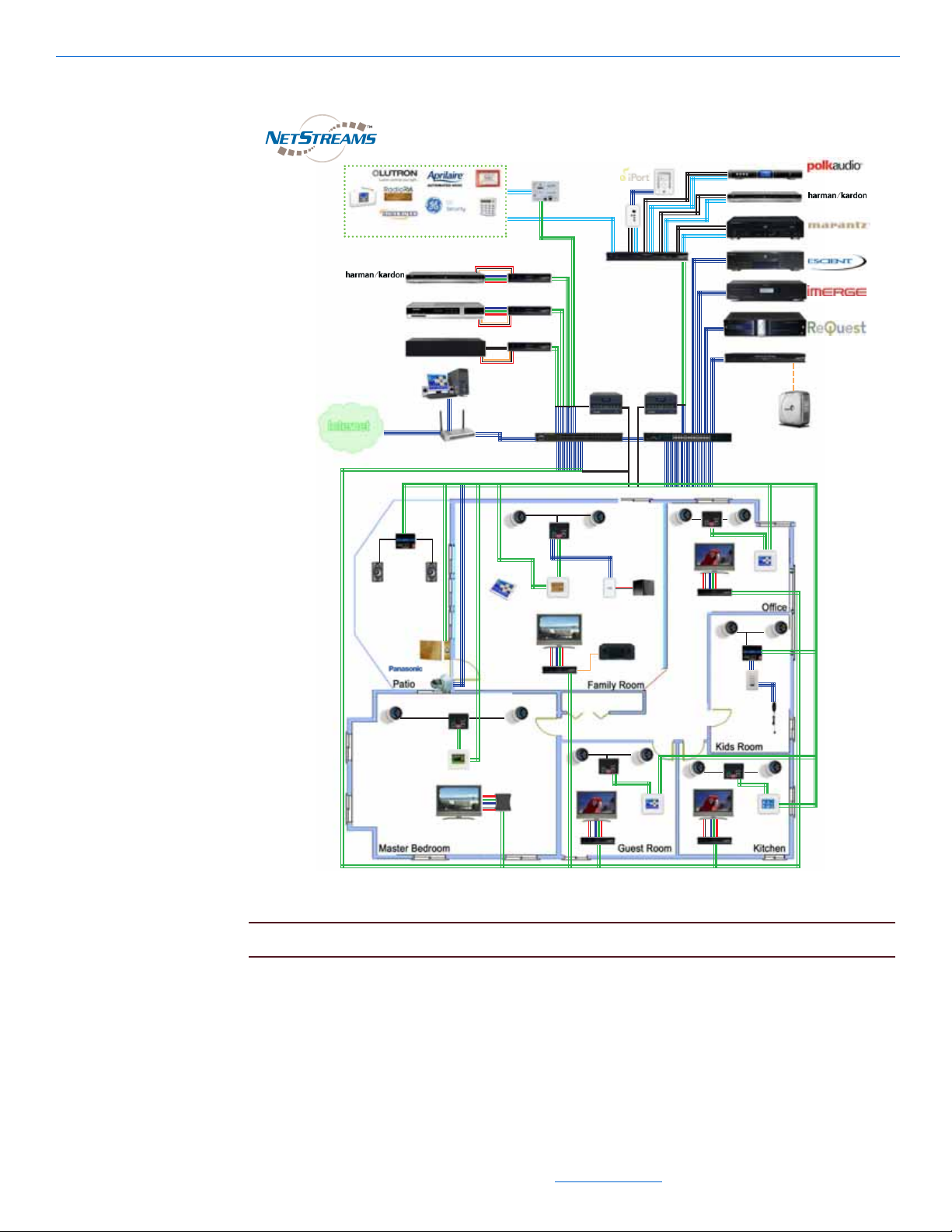
The DigiLinX™ system is an IP-based audio and video distribution and control
system. DigiLinX devices communicate with each other over a network using
Transmission Control Protocol/Internet Protocol (TCP/IP) (see Figure 1-1).
1
All specifications subject to change without notification. All rights reserved. Copyright © 2008 NetStreams
Main +1 512.977-9393 / fax +1 512.977.9398 / Toll Free Technical Support +1 866-353-3496
3600 W. Parmer Lane, Suite 100; Austin, TX 78727 / www.netstreams.com.
1-1
Page 9
DigiLinX Installation and Design Guide
DigiLinX™IP-Based Multi-Room Audio, Video and Control System
Other IR/RS-232 Controllable Systems
USB
Siamese cable CAT5 + 16/4
one to each device
Siamese cable CAT5 + 16/4
(Gigabit)
one to each device
Siamese cable CAT5 + 16/4
IR/RS-232
Line Level
VGA
CAT5 (EIM)
Control
Systems
Home Network
Switch
Seagate
®
External
USB Drive
Streaming Music
Manager
Marantz 500
DVD
XM®Tuner
MediaLinX
™
Pro
PowerLinX
™
8811
MediaLinX A/V
MLAV300
ControLinX
™
DVD
Cable Set Top Box
PC
DoorLinX
DX100
IP Camera
SpeakerLinX
SL220
SpeakerLinX
SL250
SpeakerLinX
SL250
SpeakerLinX
SL250
SpeakerLinX
SL220
KeyLinX
KL201
Audio Port
AP450
TouchLinX
TL380
Wireless
Web tablet
Polk Audio
Subwoofer
ViewLinX
VL100
ViewLinX VL100
ViewLinX VL100
TouchLinX TL380
TouchLinX TL380
SpeakerLinX SL250
ViewLinX VL100
TouchLinX TL380
ViewLinX
VL100
TouchLinX TL380
SpeakerLinX
SL250
SwitchLinX
™
SW1024
SwitchLinX
™
SW324
(vertically
mounted)
IRLinX
IRL1
Component
L, R,S/PDIF
CAT5
(EIM)
Marantz AVR
Figure 1-1 DigiLinX architecture
NOTE: Properly label all cables to facilitate installation.
Notice that there is no head end in this architecture. Each NetStreams
distributed according to its function in the network, meaning no central processor is
required.
®
device is
1-2
All specifications subject to change without notification. All rights reserved. Copyright © 2008 NetStreams
Main +1 512.977-9393 / fax +1 512.977.9398 / Toll Free Technical Support +1 866-353-3496
3600 W. Parmer Lane, Suite 100; Austin, TX 78727 / www.netstreams.com.
Page 10

Introduction
StreamNet ™ Technology
NetStreams patent-pending StreamNet technology reduces the maximum audio delay
to 1 millisecond between any two speakers and video to 30 milliseconds between any
two displays. StreamNet allows audio and video in any and all rooms to be
synchronized when playing the same source throughout the house. This technology
solves a major problem when distributing audio over TCP/IP packet-switched streams.
DigiLinX Dealer Setup
The NetStreams DigiLinX Dealer Setup is a Microsoft® Windows®-compatible
application that is used to configure all DigiLinX products. For more information on
DigiLinX Dealer Setup, download the DigiLinX Dealer Setup Manual from the Dealer
section of the NetStreams website at www.netstreams.com.
Manuals
All NetStreams manuals can be downloaded by authorized NetStreams dealers from
the Dealer section of the NetStreams website at www.netstreams.com.
Prerequisites
Before you begin installing and configuring the DigiLinX IP-Based Multi-Room
Audio, Video, and Control system, please note the following prerequisites.
Installer Requirements
This manual assumes the installer:
has completed DigiLinX Dealer Authorization Training
knows how to install audio keypads and connect audio components
knows how to use basic installation tools such as an RJ45 crimper to terminate
CAT5 cables
has pulled all necessary wire to the locations where the preamp, keypads, and
speakers are to be installed
understands basic Microsoft
®
Windows® commands such as how to browse, create
folders, save files, etc.
For more information on meeting the prerequisites, contact NetStreams Technical
Support at +1(866)353-3496.
PC Requirements
The minimum PC requirements for the DigiLinX Dealer Setup Program are:
Windows XP operating system with Service Pack 2 (SP2) or Windows Vista
NOTE: Like many software applications, the DigiLinX system is not compatible with
personal computers that run the Microsoft Vista operating system at this time.
1-3
All specifications subject to change without notification. All rights reserved. Copyright © 2008 NetStreams
Main +1 512.977-9393 / fax +1 512.977.9398 / Toll Free Technical Support +1 866-353-3496
3600 W. Parmer Lane, Suite 100; Austin, TX 78727 / www.netstreams.com.
Page 11

DigiLinX Installation and Design Guide
512 MB of RAM
1.2GHz processor (1.6GHz processor recommended).
Prior to Installation
The following are important to know before installing the DigiLinX system:
Cable Connections - Ensure all cables are connected and terminated properly.
Firewall - Temporarily disable all firewalls that may be running on your PC.
IP Addressing for third-party hardware - Set the IP address for IP cameras and
media servers prior to configuring them in DigiLinX. Consult the product user’s
guide for information on setting the IP address.
NOTE: If you have difficulty establishing a network connection after completing these
steps, call NetStreams Technical Support at +1(866)353-3496.
Additional Hardware
There are several third-party devices that can work with the DigiLinX system. Each
should be installed and set up using the manufacturer’s software before configuration
with the DigiLinX Dealer Setup program. These additional products include but are
not limited to:
Panasonic
Polk
media servers - Audio ReQuest
S3000®, and Escient Fireball
Lutron
Lutron HomeWorks
Aprilaire
Sonance
GE
Vantage
devices connected to the system through use of NetStreams’ General Purpose
®
®
IP Cameras
®
IP Speakers
®
RadioRA
®
HVAC system
®
IPort
Concord
™
™
™
®
(all models), Imerge Soundserver MKII®, Imerge
®
®
®
Driver.
1-4
NOTE: RS-232 connections for General Purpose devices are one-way only. With the
release of DigiLinX Dealer Setup v. 1.50, installers with programming
experience will be able to custom-program RS-232 drivers. See the Writing
All specifications subject to change without notification. All rights reserved. Copyright © 2008 NetStreams
Main +1 512.977-9393 / fax +1 512.977.9398 / Toll Free Technical Support +1 866-353-3496
3600 W. Parmer Lane, Suite 100; Austin, TX 78727 / www.netstreams.com.
Page 12

Introduction
StreamNet Device Drivers manual in the Dealer Documents area of the
NetStreams web site for more detail.
NOTE: If any device uses an IP address, verify that it is using an IP address that is
valid for the DigiLinX network and note the address for use later in these
procedures. We recommend the following for the IP address scheme for the
DigiLinX network, static devices, and the home network.
Device Type IP Address Range
Static (IP cameras, media
servers)
DigiLinX 192.168.0.51 - 192.168.0.200
Home Network 192.168.0.201 - 192.168.0.255
192.168.0.1 - 192.168.0.50
1-5
All specifications subject to change without notification. All rights reserved. Copyright © 2008 NetStreams
Main +1 512.977-9393 / fax +1 512.977.9398 / Toll Free Technical Support +1 866-353-3496
3600 W. Parmer Lane, Suite 100; Austin, TX 78727 / www.netstreams.com.
Page 13

DigiLinX Installation and Design Guide
1-6
All specifications subject to change without notification. All rights reserved. Copyright © 2008 NetStreams
Main +1 512.977-9393 / fax +1 512.977.9398 / Toll Free Technical Support +1 866-353-3496
3600 W. Parmer Lane, Suite 100; Austin, TX 78727 / www.netstreams.com.
Page 14

The DigiLinX system consists of several types of StreamNet devices. The following
SL9250-CS
SL250
SL220
sections discuss these devices in more detail.
SpeakerLinX™ SL220/SL250/SL254/SL9250-CS
SpeakerLinX is shown in Figure 2-1. It functions as the zone or room controller and
amplifier and has a built-in web server for the user interface.
Chapter
2
DigiLinX Devices
NOTE: For each zone of audio at least one SpeakerLinX is required.
Each zone of audio must have at least one SpeakerLinX. SpeakerLinX includes:
a digital amplifier:
2 channels at 20 watts per channel (for the SL220)
2 channels at 50 watts per channel (for the SL250 and SL9250-CS). The SL9250CS is designed for the commercial market and features balanced audio outputs.
4 channels at 25 watts per channel (used primarily for StreamNet Ready speakers
(for the SL254)
Ethernet input
line level input/output (with adapter).
Figure 2-1 SL250, SL9250-CS and SL 220
MediaLinX™ MLA101/ MLA9101-CS/ MLA4000
The MediaLinX line of source converters (Figure 2-2) are IP-Based units designed to
convert analog, or digital signals in real time from a legacy source into TCP/IP packetswitched, uncompressed (WAV) audio streams. Legacy sources can include a DVD/
CD player, AM/FM/satellite tuner, or cassette player. After conversion, analog and
2-1
All specifications subject to change without notification. All rights reserved. Copyright © 2008 NetStreams
Main +1 512.977-9393 / fax +1 512.977.9398 / Toll Free Technical Support +1 866-353-3496
3600 W. Parmer Lane, Suite 100; Austin, TX 78727 / www.netstreams.com.
Page 15

DigiLinX Installation and Design Guide
MLA101
MLA4000
digital sources as well as their transport controls are distributed over an entertainment
network via an Ethernet connection on the MediaLinX unit.
NOTE: For each analog or digital legacy audio source in your DigiLinX system, one
MediaLinX MLA101 is required. The MLA4000 can support up to four sources.
NetStreams offers two IP audio MediaLinX models.
MediaLinX MLA101and MLA9101-CS - converts from one stereo analog or
digital audio source. The MLA9101-CS is designed for the commercial market
and features balanced audio inputs also.
MediaLinX Pro MLA4000 - converts the stereo analog or digital audio of up to
four legacy audio sources. It has four definable channels, with each channel
capable of functioning as an MLA101 or ControLinX CL100. A fifth channel
provides a dedicated CL100. It also includes four contact closures and two
interfaces for a doorbell/telephone ring connector that notifies DigiLinX to mute
the audio so the ring can be heard.
MediaLinX A/V MLAV300/MLAV9300-CS
2-2
Figure 2-2 MediaLinX MLA 101,MLA9101-CS and MediaLinX Pro MLA 4000
MediaLinX A/V is an IP video component that provides real time encoding of audio
and video sources from a legacy video source into a TCP/IP uncompressed A/V stream
that can be distributed over a DigiLinX TCP/IP network at a rate of 1GB/second. The
MediaLinX A/V MLAV300 features component, S-video, composite or VGA video
inputs as well as analog and S/PDIF RCA audio inputs for maximum connection
flexibility. The MediaLinX A/V MLAV9300-CS is specifically designed for the needs
of the commercial market and features BNC connectors, as well as balanced audio
inputs.
All specifications subject to change without notification. All rights reserved. Copyright © 2008 NetStreams
Main +1 512.977-9393 / fax +1 512.977.9398 / Toll Free Technical Support +1 866-353-3496
3600 W. Parmer Lane, Suite 100; Austin, TX 78727 / www.netstreams.com.
Page 16

Figure 2-3 MediaLinX A/V
DigiLinX Devices
2-3
All specifications subject to change without notification. All rights reserved. Copyright © 2008 NetStreams
Main +1 512.977-9393 / fax +1 512.977.9398 / Toll Free Technical Support +1 866-353-3496
3600 W. Parmer Lane, Suite 100; Austin, TX 78727 / www.netstreams.com.
Page 17

DigiLinX Installation and Design Guide
SMM100
ViewLinX™ VL100/ VL9100-CS
ViewLinX is an IP Video component that provides for real time decoding of a TCP/IP
uncompressed A/V stream from the DigiLinX gigabit network into an analog or
S/PDIF audio signal and a component, composite S-Video or VGA video signal for
output to a display. Designed for installation at or near the location of the video
display, ViewLinX also encode audio from a TV monitor output for listening on
networked speakers in a room. The VL9100-CS is designed for the commercial
market and features BNC connectors, and balanced audio outputs. Additionally, the
VL9100-CS features support for the NetStreams Multimedia wall plate that allows the
integrator to extend the ouput 150 feet or 50 meters from the ViewLinX. The
Multimedia wall plate also supports the same output from both the ViewLinX and wall
plate simultaneously.
Figure 2-4 ViewLinX VL100
Streaming Music Manager SMM100
The Streaming Music Manager SMM100 is a hardware device designed to search a
computer network for MP3 and WAV music files and playlists. It builds a database and
makes them available to the DigiLinX network. DigiLinX users can then browse the
database, locate files, and view metadata such as cover art. See Figure 2-5.
Figure 2-5 Streaming Music Manager SMM100
ControLinX™ CL100/ CL9100-CS
The ControLinX CL100 (shown in Figure 2-6) allows you to easily integrate and
control supported brands of lighting, automated heating, cooling, security and other
third party systems with your DigiLinX system. The ControLinX CL100 enables
control of non-IP-Based sources from DigiLinX using RS-232, IR, or voltage sensing.
The CL100 features a two-pin Phoenix connector for power and an Ethernet connector
to connect to your DigiLinX network. Each third party system requires one CL100.
Multiple CL100s can be connected to a SwitchLinX. The CL9100-CS is specifically
designed for the commercial market and features the same foot print (1U high, 1/2 rack
wide) as the other commercial products.
2-4
All specifications subject to change without notification. All rights reserved. Copyright © 2008 NetStreams
Main +1 512.977-9393 / fax +1 512.977.9398 / Toll Free Technical Support +1 866-353-3496
3600 W. Parmer Lane, Suite 100; Austin, TX 78727 / www.netstreams.com.
Page 18
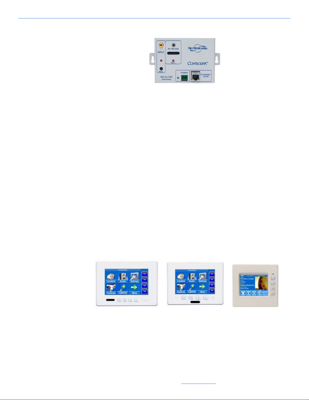
Figure 2-6 ControLinX CL100
TL700
TL430
TL380
TouchLinX™ TL380/TL430/TL700
Three models of TouchLinX are available:
TL380
TL430
TL700
TouchLinX TL380 is a 3.8-inch, in-wall touch screen (Figure 2-7) that includes a fourport Ethernet switch and power input/output for distribution. This device includes
DigiLinX Devices
Adobe® Flash®.
TouchLinX TL430 features a 4.3-inch Thin-Film Transistor (TFT) color touch screen,
while the TL700 features a 7-inch TFT color touch screen. Both the TL430 and TL700
feature a Windows CE embedded operating system. Both devices also include Adobe
Flash. The TL430 and TL700 have a 2-port Ethernet switch and 4-pin connector for
communications, power, and cascading one SpeakerLinX. Additionally, both the
TL430 and TL700 feature a built-in microphone for IP Intercom, including whole
house paging, room to room paging, and room monitoring via the DigiLinX system.
Both the TL430 and 700 feature IR support.
Figure 2-7 TouchLinX TL700, TL430 and TL380
2-5
All specifications subject to change without notification. All rights reserved. Copyright © 2008 NetStreams
Main +1 512.977-9393 / fax +1 512.977.9398 / Toll Free Technical Support +1 866-353-3496
3600 W. Parmer Lane, Suite 100; Austin, TX 78727 / www.netstreams.com.
Page 19

DigiLinX Installation and Design Guide
SW1024
SW208
SW324
SW208
SwitchLinX™ SW324/SW208/SW1024/SW1124/SW1148
SwitchLinX is a family of IGMP (Internet Group Management Protocol) enabled,
multicasting, non-blocking 10/100Mbps Fast Ethernet and 10/100/1000 Gigabit
Ethernet switches. SwitchLinX is designed specifically for handling the high demands
of networked audio and video distribution products. Additional SwitchLinX can be
employed to expand the number of network connections.
There are four sizes of SwitchLinX depending on what is required for your project
(Figure 2-8):
SW208 - 8 10/100 Mbps ports
SW324 - 24 10/100 Mbps ports
SW1024 - 24 10/100/1000 Mbps ports
NOTE: The SW1024 is limited to 64 multicast IP addresses. If you need more multicast IP
addresses, you will need to add an additional device.
SW1124 - 24 10/100/1000 Mbps ports
SW1148 - 48 10/100/1000 Mbps ports
2-6
IRLinX™ IRL1
Figure 2-8 SwitchLinX SW324/SW208/SW1024
IRLinX (Figure 2-9) allows DigiLinX to receive IR commands in zones that do not
have an IR receiver. It provides installers with the flexibility to locate the IR receiver in
a convenient location to meet the homeowner’s needs. IRLinX processes DigiLinX
native IR commands such as volume up, volume down, and mute, from an IR remote.
All specifications subject to change without notification. All rights reserved. Copyright © 2008 NetStreams
Main +1 512.977-9393 / fax +1 512.977.9398 / Toll Free Technical Support +1 866-353-3496
3600 W. Parmer Lane, Suite 100; Austin, TX 78727 / www.netstreams.com.
Page 20
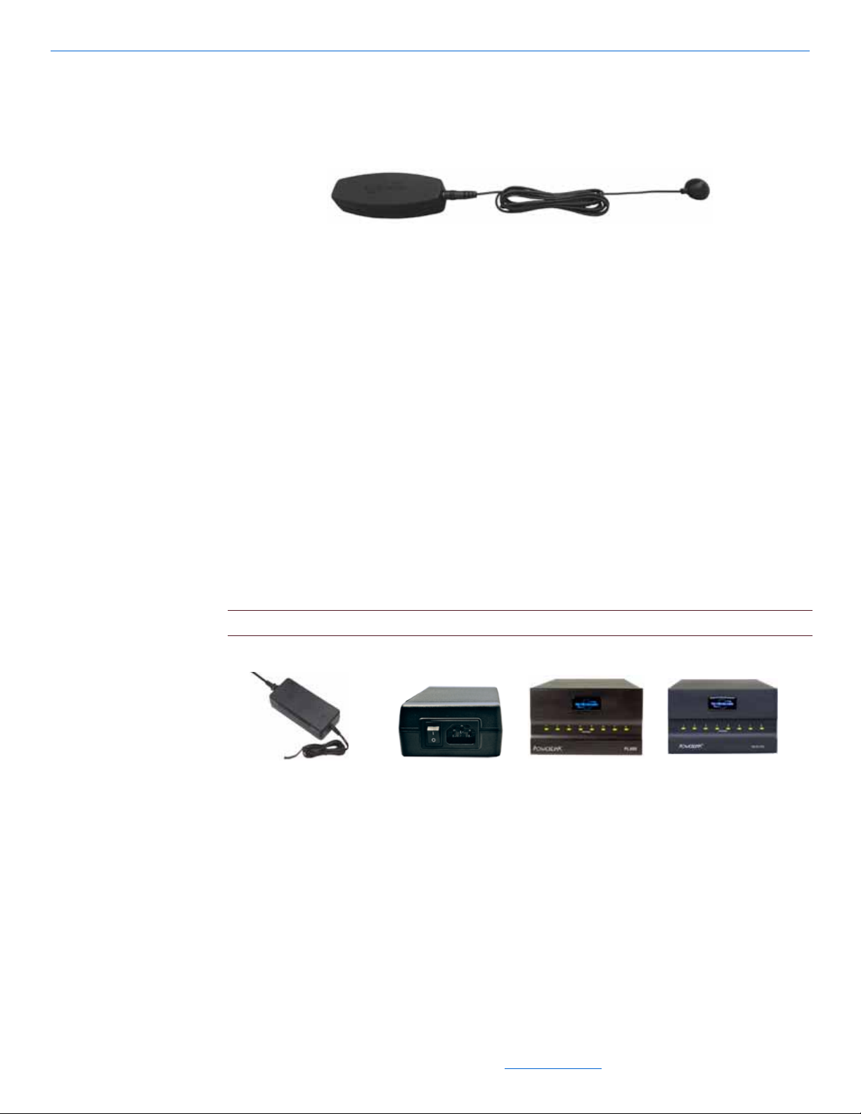
IRLinX will also accept IR commands from a source’s original remote, or universal
PL228
PL250
PL600
PL750
remote, and pass them on to the active source using network IR pass-through.
Figure 2-9 IRLinX
PowerLinX™ PL228/PL250/PL600/PL750/PL751
PowerLinX is a family of power supplies for the DigiLinX system. There are four sizes
of PowerLinX depending on what is required for your project (as shown in Figure 2-
10):
PL228 - designed to distribute 2.96A max @ 28VDC and can power one
SpeakerLinX SL220, MediaLinX, ControLinX, or TouchLinX. The PowerLinX
PL228 is a local power supply and is the perfect solution for retrofit installations.
DigiLinX Devices
PL250 - designed to distribute 3.57A max @ 28VDC to power one SL250,
SpeakerLinX and TouchLinX.
PL600 - designed to distribute 21A max @ 28VDC of power, to multiple DigiLinX
products (do not use with SL250s).
PL750/PL751 - designed to distribute 27A max @ 28VDC of power to multiple
DigiLinX products on an IP-Based Multi-Room Audio network (can be used with
all DigiLinX products).
NOTE: The SpeakerLinX 250 requires the use of the PL750/PL751 or PL250.
Figure 2-10 PowerLinX
DoorLinX™ DX100
DoorLinX enhances the IP intercom functionality in DigiLinX systems by providing a
front door intercom to communicate with guests and a means to remotely unlock the
door. The homeowner can also use a customized MP3 doorbell that plays throughout
the DigiLinX system, or in specific designated rooms.
All specifications subject to change without notification. All rights reserved. Copyright © 2008 NetStreams
Main +1 512.977-9393 / fax +1 512.977.9398 / Toll Free Technical Support +1 866-353-3496
3600 W. Parmer Lane, Suite 100; Austin, TX 78727 / www.netstreams.com.
2-7
Page 21

DigiLinX Installation and Design Guide
DXF100 DX100 DXB100
Figure 2-11 DoorLinX
DoorLinX can be purchased as follows:
mounting bracket (DXB100)
electronics package and chassis (DX100)
faceplate and doorbell (DXF100-B brushed brass, DXF100-N brushed nickel, or
DXF100-O venetian bronze).
Power Requirements for DigiLinX Devices
A NetPower calculator and power ratings chart are used to allow you to determine
power requirements for DigiLinX devices.
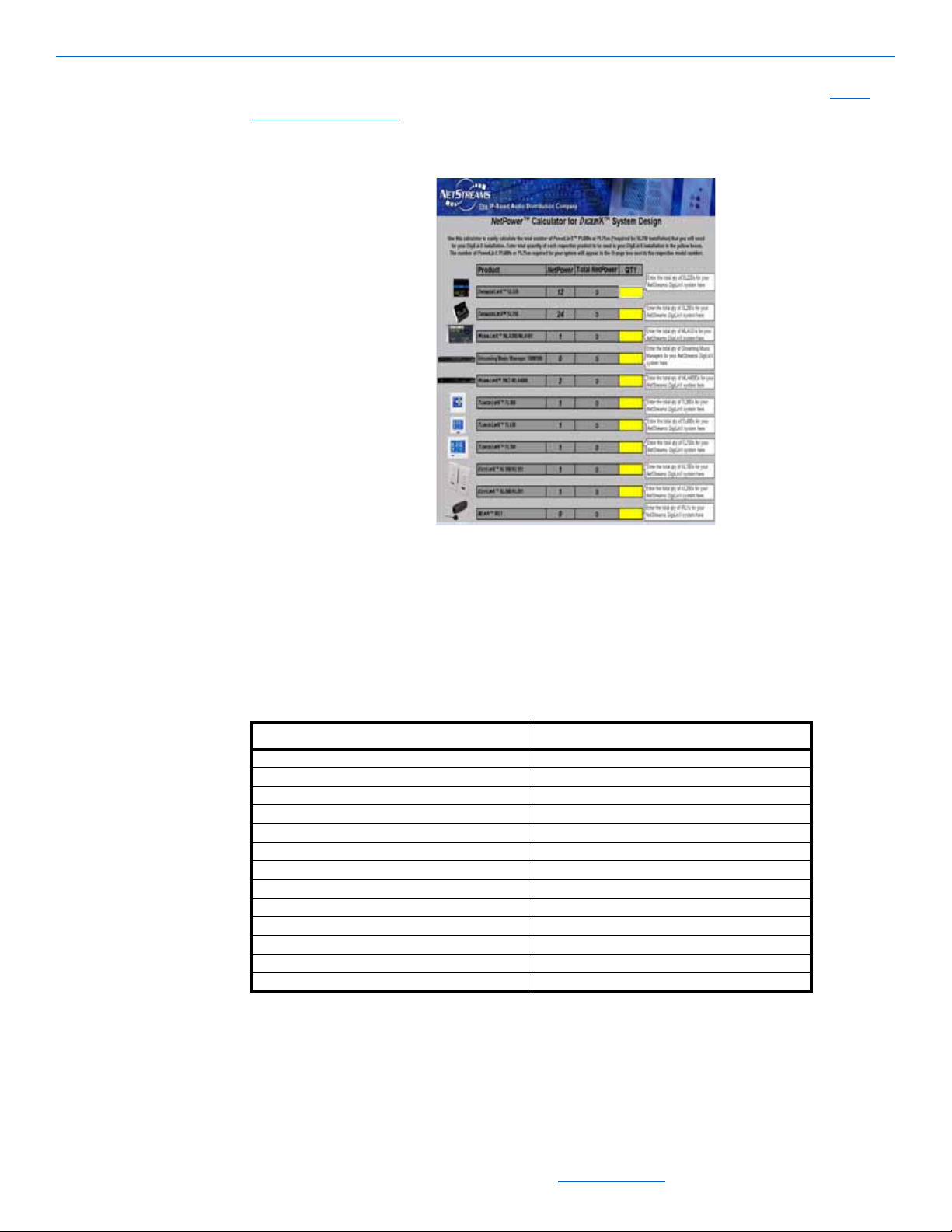
NetPower™ Calculator
NetStreams offers an online NetPower calculator to assist in determining how many
PowerLinX units your DigiLinX system requires. See Figure 2-12 for an example of
this software interface.
2-8
All specifications subject to change without notification. All rights reserved. Copyright © 2008 NetStreams
Main +1 512.977-9393 / fax +1 512.977.9398 / Toll Free Technical Support +1 866-353-3496
3600 W. Parmer Lane, Suite 100; Austin, TX 78727 / www.netstreams.com.
Page 22
DigiLinX Devices
You can download the NetPower Calculator from the NetStreams web site at http://
www.netstreams.com. It is located in the Dealer Documents section under DigiLinX
Tools.
Figure 2-12 NetPower Calculator
NetPower Ratings
To assist in determining how many PL600’s and PL750’s a project requires, each
DigiLinX product comes with a NetPower rating as shown in Table 2-1.
1
1 SpeakerLinX SL250/254/9250-CS 24
1 SpeakerLinX SL220 12
1 MediaLinX A/V (MLAV300 and 9300-CS) 4
1 ViewLinX (VL100 and 9100-CS) 4
1 MediaLinX MLA4000 2
1 MediaLinX MLA100 1
1 MediaLinX MLA101/MLA9101-CS 1
1 TouchLinX TL380 1
1 KeyLinX KL101 1
1 KeyLinX KL201 1
1 ControLinX CL100/CL9101-CS 1
1 DoorLinX DX100 1
1 IRLinX IRL1 1
Table 2-1
NetPower Ratings
Model NetPower Rating
When designing your DigiLinX system, add the NetPower rating for all devices
planned and choose the appropriate quantity of PowerLinX power supplies as follows:
2-9
All specifications subject to change without notification. All rights reserved. Copyright © 2008 NetStreams
Main +1 512.977-9393 / fax +1 512.977.9398 / Toll Free Technical Support +1 866-353-3496
3600 W. Parmer Lane, Suite 100; Austin, TX 78727 / www.netstreams.com.
Page 23

DigiLinX Installation and Design Guide
KL101
KL201
Legend
CAT5
Each PL228 can support one SpeakerLinX, MediaLinX, or TouchLinX.
NOTE: The SpeakerLinX SL250 requires the use of the PL750 or PL250.
Each PL250 can support one SL250 SpeakerLinX and one TouchLinX.
Each PL600 can support DigiLinX devices that equal a total NetPower of 84 or
less, unless an SL250 is in the project. If an SL250 is in the project, you must use a
PL750.
Each PL750 can support DigiLinX devices that equal a total NetPower of 168 or
less.
EIM Products
The Expansion Interface Module (EIM) port on a SpeakerLinX provides an interface
for additional audio and control products.
KeyLinX™ KL101/201
The KeyLinX KL101 and KL201(as shown in Figure 2-13) are single-gang, in-wall
hard button keypads that control up to four audio sources with presets. Both models
feature an IR window for IR pass-through to a local source connected to an Audio Port.
The KL201 also features an embedded microphone and a Talk button for IP intercom.
Both products connect to the SpeakerLinX and Audio Port using an EIM splitter and
CAT5 cable (see Figure 2-14). Both products also have an additional connection for an
IRLinX.
Figure 2-13 KeyLinX 101 and 201
NOTE: The EIM CAT5 cable length of all EIM connections together cannot be more than 60
ft total.
2-10
All specifications subject to change without notification. All rights reserved. Copyright © 2008 NetStreams
Main +1 512.977-9393 / fax +1 512.977.9398 / Toll Free Technical Support +1 866-353-3496
3600 W. Parmer Lane, Suite 100; Austin, TX 78727 / www.netstreams.com.
Page 24
DigiLinX Devices
MU290
Figure 2-14 Connecting a SpeakerLinX using an EIM splitter
MU290
The SpeakerLinX built-in amplifier provides the sufficient power for most
installations. But if you need more power for a larger zone, or outdoor application, or
you just really want to push the envelope, the MU290 is the solution. This high
performance power amplifier delivers 100 watts/channel into 4 ohms, 200 watts
bridged for high quality audio output. You can also daisy-chain up to six MU290s for a
total of 600 watts of stereo power or 1200 watts bridged power. The MU290 connects
directly to a Musica keypad or SpeakerLinX via RJ45 connectors (labeled EIM).
Figure 2-15 MU290
AMP2200
The AMP2200 Professional Amplifier is an alternative for the MU290, providing 200
watts per channel at 8 ohms and 600 watts bridged. Up to 6 AMP2200 can be daisy
chained together. The AMP2200 connects to the SpeakerLinX via a RJ45 connector,
labeled EIM.
2-11
All specifications subject to change without notification. All rights reserved. Copyright © 2008 NetStreams
Main +1 512.977-9393 / fax +1 512.977.9398 / Toll Free Technical Support +1 866-353-3496
3600 W. Parmer Lane, Suite 100; Austin, TX 78727 / www.netstreams.com.
Page 25

DigiLinX Installation and Design Guide
EIM2RCA Adapter
Figure 2-16 AMP2200
Audio Port
The Audio Port makes it easy to connect a local audio device. There are several models
of Audio Port to choose from:
The AP300 provides the SpeakerLinX with line level audio in and out using stereo
RCA connectors. The AP300 also has an IR out to control local audio sources. This
IR out can also be configured to function as an audio in. Audio outputs are also
provided, which are useful for subwoofers or receivers.
The AP450 is designed for rooms only requiring line level audio output. This is
commonly used with subwoofers.
The AP500 has stereo RCA connections for line level audio in and out as well as a
connector for IR out.
2-12
Figure 2-17 Audio Port AP500
EIM2RCA Adapter
You can use the EIM2RCA adapter when you don’t want to install a faceplate in your
wall and you want to connect a SpeakerLinX with an external power amplifier or
source (such as an A/V receiver for a home theater). The EIM2RCA adapter has one
RJ45 connector on one end and two stereo pairs of RCA female connectors on the
other end for input and output.
Figure 2-18 EIM2RCA adapter
All specifications subject to change without notification. All rights reserved. Copyright © 2008 NetStreams
Main +1 512.977-9393 / fax +1 512.977.9398 / Toll Free Technical Support +1 866-353-3496
3600 W. Parmer Lane, Suite 100; Austin, TX 78727 / www.netstreams.com.
Page 26
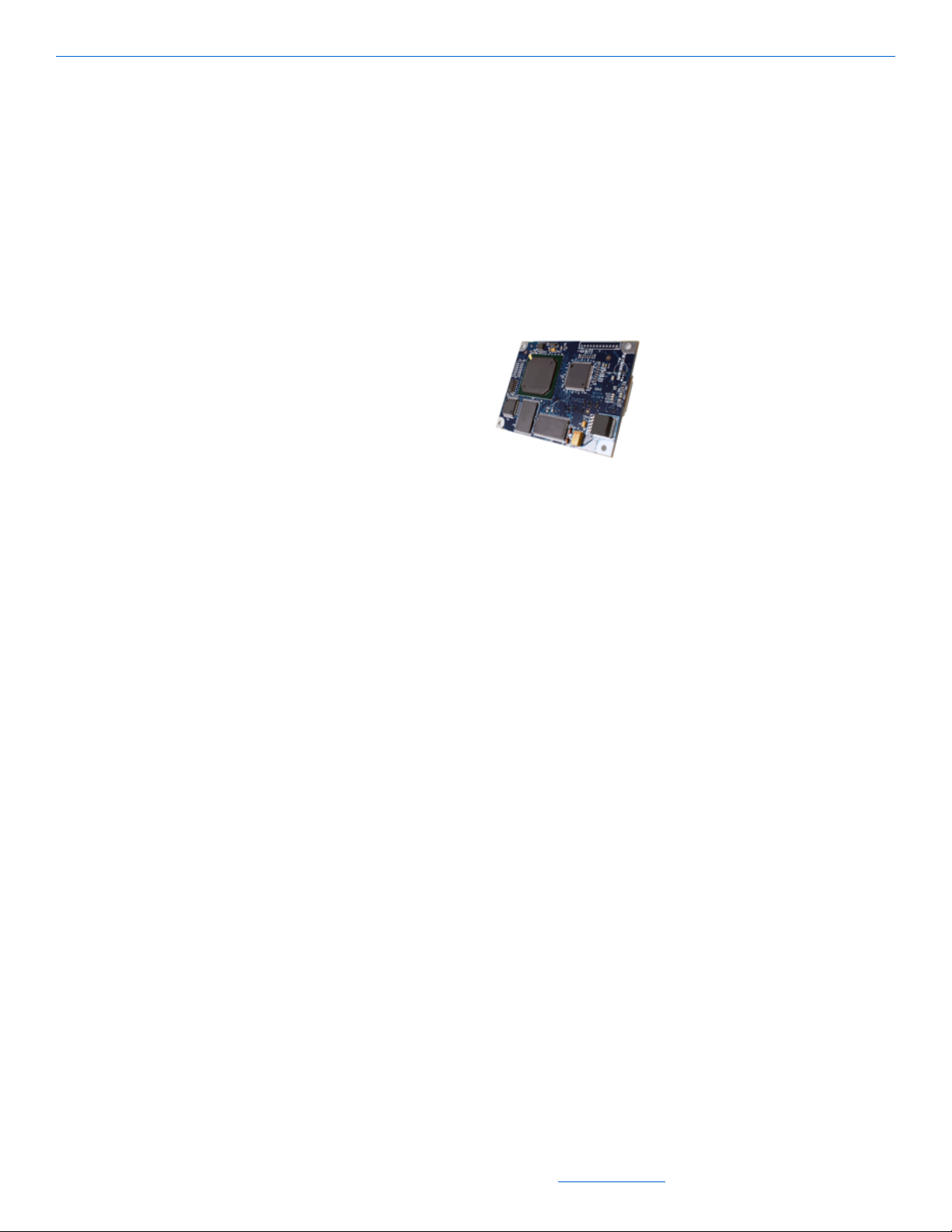
StreamNet Card
NetStreams also offers our technology in the form of a StreamNet card. This card can
be used to enable Polk Audio’s® IP-Addressable in-wall and in-ceiling speakers to
become addressable nodes on a NetStreams DigiLinX network. Because these speakers
contain built-in amplifiers, this eliminates the need for a SpeakerLinX in rooms where
the Polk Audio LC265i-IP or LC80i-IP speakers and a StreamNet card are installed.
Refer to Tech Bulletin 040017, Installing a StreamNet Card into a Polk Speaker for
more details. The StreamNet card can also be used by other devices.
Figure 2-19 StreamNet Card
DigiLinX Devices
2-13
All specifications subject to change without notification. All rights reserved. Copyright © 2008 NetStreams
Main +1 512.977-9393 / fax +1 512.977.9398 / Toll Free Technical Support +1 866-353-3496
3600 W. Parmer Lane, Suite 100; Austin, TX 78727 / www.netstreams.com.
Page 27

DigiLinX Installation and Design Guide
2-14
All specifications subject to change without notification. All rights reserved. Copyright © 2008 NetStreams
Main +1 512.977-9393 / fax +1 512.977.9398 / Toll Free Technical Support +1 866-353-3496
3600 W. Parmer Lane, Suite 100; Austin, TX 78727 / www.netstreams.com.
Page 28

Introduction
This chapter covers pre-wiring for a DigiLinX audio and video network. DigiLinX
architecture is similar to the architecture used in computer networking. You require
devices, a network connection, and power.
Pre-Wiring for IP Audio
Chapter
3
Pre-Wiring for IP Audio and IP Video
Requirements
Cables
The following cables are required to pre-wire for DigiLinX IP audio:
NOTE: When wiring for Ethernet, do not exceed 100 meter (328 foot) cable runs.
Siamese CAT5 16/4 (or CAT5 14/4) AWG cable
RG6 cable
CAT5e cable.
Terminating Wires
The following are required to terminate wires:
RJ45 crimpers
CAT5 stripper
wire cutters/strippers
small flat-head screw driver
RJ45 connectors
Phoenix connectors (for power and speaker connections). These are provided with
your NetStreams system.
All specifications subject to change without notification. All rights reserved. Copyright © 2008 NetStreams
Main +1 512.977-9393 / fax +1 512.977.9398 / Toll Free Technical Support +1 866-353-3496
3600 W. Parmer Lane, Suite 100; Austin, TX 78727 / www.netstreams.com.
3-1
Page 29

DigiLinX Installation and Design Guide
To terminate wires, use the 568a standard (see Table 3-1).
Ethernet 568a Standard for
Terminating Wires
Pin 1 White/Green
Pin 2 Green
Pin 3 White/Orange
Pin4 Blue
Pin 5 White/Blue
Pin 6 Orange
Pin 7 White/Brown
Pin 8 Brown
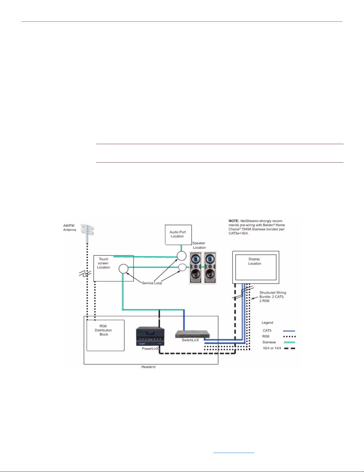
Example
Figure 3-1 shows an example of how to pre-wire a room for DigiLinX audio.
NOTE: This diagram is a general overview of audio pre-wiring and is subject to change
depending on the design of the system. This pre-wire will allow you to grow with technology.
Table 3-1
Procedures
Figure 3-1 Pre-Wiring Diagram for DigiLinX
The following pre-wire procedure is designed to allow DigiLinX or Musica to later be
installed. To pre-wire a room, complete the following steps:
1. From the head end, run a siamese CAT5 16/4 (or CAT5 14/4) cable to the touch
screen location.
2. Leave a service loop at this location and continue (do not cut the cable) to the first
speaker location in the room.
3. Leave a service loop at this location and continue (do not cut the cable) to the
second speaker location.
4. Cut the cable.
5. From the touch screen location, run a siamese CAT5 16/4 (or CAT5 14/4) cable to
the first speaker location.
6. Leave a service loop and continue (do not cut the cable) using a different route to
the wall location chosen for the Audio Port installation.
7. Cut the cable.
8. From the head end, run an RG6 cable to the touch screen location.
9. From the head end, run an RG6 cable to a location for an antenna to be mounted.
This will be used for antenna distribution.
3-2
10. From the head end, run a siamese 16/4 or 14/4 cable to the display location.
11. From the head end, run a standard structured wiring bundle (2 CAT5, 2 RG6) to the
display location.
12. Run an RG6 cable from the display location.
All specifications subject to change without notification. All rights reserved. Copyright © 2008 NetStreams
Main +1 512.977-9393 / fax +1 512.977.9398 / Toll Free Technical Support +1 866-353-3496
3600 W. Parmer Lane, Suite 100; Austin, TX 78727 / www.netstreams.com.
Page 30
13. Repeat steps 1 through 8 for each pre-wired room.
Pre-Wire for IP Video
Requirements
one structured wire consisting of two twisted pair (CA T5e or better) cables and two
coaxial cables (RG6 or better)
one four-port flush mounted wall plate consisting of two RJ45 connectors and two
F connectors
one 16/4 DC power cable
NOTE: You can also use a NetStreams local power supply such as a PL228 or PL250 to power
NetStreams IP video products at the display location.
Procedures
Pre-Wiring for IP Audio and IP Video
Figure 3-2 shows how to pre-wire for IP-Based video.
Figure 3-2 Pre-Wiring for IP-Based Video
3-3
All specifications subject to change without notification. All rights reserved. Copyright © 2008 NetStreams
Main +1 512.977-9393 / fax +1 512.977.9398 / Toll Free Technical Support +1 866-353-3496
3600 W. Parmer Lane, Suite 100; Austin, TX 78727 / www.netstreams.com.
Page 31

DigiLinX Installation and Design Guide
To pre-wire for IP-Based video, complete the following steps:
1. Install a four-port flush mounted wall plate (with CAT5e and RG6 connections) at
the video location.
NOTE: If you are installing a home theater system, also install a four-port flush mounted wall
plate (with CAT5e and RG6 connections) near the theate r equipment.
2. From the head end, run the structured cable to the four-port flush mounted wall
plate.
3. From the head end, run a 16/4 cable for power.
4. Terminate using 568A terminations on the CAT5e cables.
5. Terminate F type connections on the RG6 cables.
NOTE: None of the runs should exceed 328 feet maximum cable length.
3-4
All specifications subject to change without notification. All rights reserved. Copyright © 2008 NetStreams
Main +1 512.977-9393 / fax +1 512.977.9398 / Toll Free Technical Support +1 866-353-3496
3600 W. Parmer Lane, Suite 100; Austin, TX 78727 / www.netstreams.com.
Page 32

Chapter
4
SpeakerLinX
The SpeakerLinX is the heart of the DigiLinX system. It contains a built-in web server
and amplifier, and can be placed installed nearly anywhere. Typically, the
SpeakerLinX is installed very close to the speakers.
CAUTION! Connecting the power connector incorrectly or plugging the power
connector into the speaker connection causes damage to the amplifier and voids the
warranty.
SL220 Specifications
8 Ohms Stereo Power 20 watts/channel
4 Ohms Stereo Power 12 watts/channel
Frequency Response 20-20KHz, +/-db
Signal-to-Noise Ratio 95 dB
Input Impedance 17K Ohms
THD +N 1% (20 Hz to 20KHz)
Input Connectors RJ45 (EIA568a)
Output Connectors 4-pin Phoenix
Dimensions 3.625” high x 2.875” wide x 1.75” deep
Weight 0.5 lbs. (0.23Kg)
NetPower 12
@8 Ohms
Connector (speakers)
(91mm x 72mm x 44mm)
SL250 Specifications
8 Ohms Stereo Power 35 watts/channel RMS
All specifications subject to change without notification. All rights reserved. Copyright © 2008 NetStreams
Main +1 512.977-9393 / fax +1 512.977.9398 / Toll Free Technical Support +1 866-353-3496
3600 W. Parmer Lane, Suite 100; Austin, TX 78727 / www.netstreams.com.
4-1
Page 33

DigiLinX Installation and Design Guide
4 Ohms Stereo Power 50 watts/channel RMS
Frequency Response 20-20KHz +/-1dB
Signal-to-Noise Ratio 98 dB
Input Impedance 17K Ohms
THD +N 0.1% (20 Hz to 20 KHz@8 Ohms)
Dimensions 3.65” wide x 2.875” high x 1.75” deep
Weight 0.5lbs (.023 Kg)
NetPower 24
SL254 Specifications
8 Ohms Stereo Power 20 watts/channel RMS
0.1% (20 Hz to 20KHz@4 Ohms)
(91mm x 72mm x 44mm)
4 Ohms Stereo Power 25 watts/channel RMS
Frequency Response 20-20KHz +/-1dB
Signal-to-Noise Ratio 98 dB
Input Impedance 17K Ohms
THD +N 0.1% (20 Hz to 20 KHz@8 Ohms)
Dimensions 3.65” wide x 2.875” high x 1.75” deep
Weight 0.5lbs (.023 Kg)
NetPower 24
SL9250-CS Specifications
8 Ohms Stereo Power 35 watts/channel RMS
4 Ohms Stereo Power 50 watts/channel RMS
Frequency Response 20-20KHz +/-1dB
0.1% (20 Hz to 20KHz@4 Ohms)
(91mm x 72mm x 44mm)
4-2
Signal-to-Noise Ratio 98 dB
Input Impedance 17K Ohms
THD +N 0.1% (20 Hz to 20 KHz@8 Ohms)
0.1% (20 Hz to 20KHz@4 Ohms)
All specifications subject to change without notification. All rights reserved. Copyright © 2008 NetStreams
Main +1 512.977-9393 / fax +1 512.977.9398 / Toll Free Technical Support +1 866-353-3496
3600 W. Parmer Lane, Suite 100; Austin, TX 78727 / www.netstreams.com.
Page 34

Connections
SL220
SL250
Balanced Audio Ouput
Line out
EIM
Speaker Out
Ethernet
Power
SpeakerLinX
Dimensions 9.5” wide x 1.75” high x 8.67” deep
(244mm x 45mm x 220mm)
Weight 3.57lbs (1.62 Kg)
NetPower 24
Figure 4-1 shows the connectors on the SL220 and SL250.
Figure 4-1 SpeakerLinX SL220 and SL250 Connections
Figure 4-2 SpeakerLinX SL9250-CS Connections
4-3
All specifications subject to change without notification. All rights reserved. Copyright © 2008 NetStreams
Main +1 512.977-9393 / fax +1 512.977.9398 / Toll Free Technical Support +1 866-353-3496
3600 W. Parmer Lane, Suite 100; Austin, TX 78727 / www.netstreams.com.
Page 35

DigiLinX Installation and Design Guide
Connectors
Connectors for the SL220, SL250, SL254, and SL9250-CS include:
Input Connectors (SL220, 250, 254):
RJ45 (EIA 568a)
RJ45 (EIM use EIA 568a)
4-pin Phoenix connector (Power) on SL250
2-pin Phoenix connector (Power) on SL220
Output Connectors: 4-pin Phoenix Connector (speakers) (2 4-pin connectors on the
SL254)
Input Connectors (SL9250)
RJ45 (EIA 568a)
RJ45 (EIM)
4-pin Phoenix connector (Power)
Output Connectors: 4-pin Phoenix Connector (speakers), 3-Position Phoenix
Connector for balanced audio output
Installation
Installing a Surface-Mounted SpeakerLinX
The SpeakerLinX can be surface-mounted at the speaker (recommended) or to a secure
location (such as a wall stud). To perform this installation, you need:
an SL220 or SL250 or SL254
a SpeakerLinX Surface Mounting Plate (NS-MKSL220-SM) - mounts either the
SL220 or SL250 or SL254
#6 or #8 wood screws (not provided).
To complete the installation:
IMPORTANT! If you are mounting in an attic, ensure that the device will not be
covered by insulation, and that there is 1 ft. of air space around the SpeakerLinX.
1. Screw the surface mounting plate either to the back of a speaker or to a secure loca-
tion (like a wall stud).
4-4
All specifications subject to change without notification. All rights reserved. Copyright © 2008 NetStreams
Main +1 512.977-9393 / fax +1 512.977.9398 / Toll Free Technical Support +1 866-353-3496
3600 W. Parmer Lane, Suite 100; Austin, TX 78727 / www.netstreams.com.
Page 36

SpeakerLinX
2. Install the SpeakerLinX by sliding the bottom of the device into the clip and
pushing back until you feel it snap into place (see Figure 4-3).
3. Connect all wires.
Figure 4-3 Wall mounting a SpeakerLinX
Installing a Wall-Mounted SpeakerLinX
The SpeakerLinX can be wall-mounted into walls that are 2 1/2” (64mm) or deeper. To
perform this installation, you need:
an SL220 or SL250 or SL254
a standard 2-gang box
a SpeakerLinX In-Wall Mounting Plate (NS-MKSL220-IW) - mounts either the
SL220 and SL250 or SL254.
To complete the installation:
1. Install a 2-gang box at the location.
2. Attach the SpeakerLinX to the metal mounting plate.
3. Connect all wires.
4. Insert the SpeakerLinX into the 2-gang box with the connection pointed into the
wall.
5. Screw the metal mounting plate to the box.
6. Snap the in-wall plate over the metal plate.
Installing a SpeakerLinX into a Rack
The SpeakerLinX can be installed into a rack location. To perform this installation,
you need:
an SL220 or SL250 or SL254
4-5
All specifications subject to change without notification. All rights reserved. Copyright © 2008 NetStreams
Main +1 512.977-9393 / fax +1 512.977.9398 / Toll Free Technical Support +1 866-353-3496
3600 W. Parmer Lane, Suite 100; Austin, TX 78727 / www.netstreams.com.
Page 37

DigiLinX Installation and Design Guide
an RP24/RP25 rack mount plate (sold separately).
The SL9250-CS will mount directly into a rack using the include rack mount ears.
To install a SpeakerLinX into a rack, complete the following steps:
1. Screw the SpeakerLinX’ (up to four) onto the rack mount plate (see Figure 4-4).
2. Screw the rack mount plate to the back of the rack.
Figure 4-4 SpeakerLinX rack mount
3.
Screw the rack mount plate cover in place, if desired (see Figure 4-5).
Figure 4-5 Rack mount plate cover
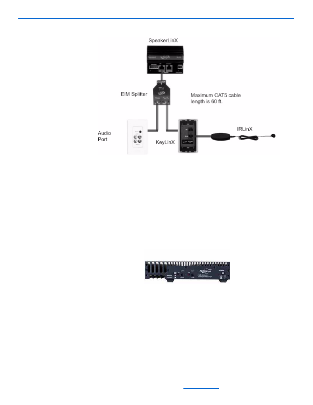
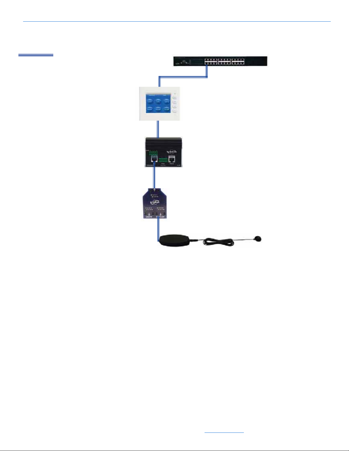
Installing a SpeakerLinX with an IRLinX and TouchLinX
The SpeakerLinX can be installed with an IRLinX via an EIM splitter as shown in
Figure 4-6. Follow these steps to connect an IRLinX and a TouchLinX to a
SpeakerLinX.
1. Connect the TouchLinX to the SpeakerLinX connector labeled Ethernet.
2. Locate the EIM splitter under the cardboard at the bottom of the IRLinX box.
3. Connect the EIM splitter to the SpeakerLinX connector labeled EIM using the
provided 1 foot CAT5 cable.
4. Connect the IRLinX to the EIM splitter connector labeled KeyLinX.
5. Connect the TouchLinX to the SwitchLinX.
4-6
NOTE: Only one SpeakerLinX can be plugged into a TouchLinX.
All specifications subject to change without notification. All rights reserved. Copyright © 2008 NetStreams
Main +1 512.977-9393 / fax +1 512.977.9398 / Toll Free Technical Support +1 866-353-3496
3600 W. Parmer Lane, Suite 100; Austin, TX 78727 / www.netstreams.com.
Page 38
SpeakerLinX
Legend
CAT5
Figure 4-6 SpeakerLinX, IRLinX, and TouchLinX configuration
4-7
All specifications subject to change without notification. All rights reserved. Copyright © 2008 NetStreams
Main +1 512.977-9393 / fax +1 512.977.9398 / Toll Free Technical Support +1 866-353-3496
3600 W. Parmer Lane, Suite 100; Austin, TX 78727 / www.netstreams.com.
Page 39

DigiLinX Installation and Design Guide
4-8
All specifications subject to change without notification. All rights reserved. Copyright © 2008 NetStreams
Main +1 512.977-9393 / fax +1 512.977.9398 / Toll Free Technical Support +1 866-353-3496
3600 W. Parmer Lane, Suite 100; Austin, TX 78727 / www.netstreams.com.
Page 40

MediaLinX
Analog Audio Out
(passthrough)
IR receiver window
Sensitivity
adjustment for
video sensor
ID button
Power input
connector
Ethernet (network)
connection
Digital Audio Out
(passthrough)
Video Sensor
Out (video
passthrough)
RS-232/IR Out
Analog Audio In
Digital Audio In
Video Sensor
In
The MediaLinX line of source converters includes the MediaLinX MLA101 and
MediaLinX Pro MLA4000.
MediaLinX MLA 101
Figure 5-1 shows the front panel of the MLA101.
Chapter
5
Figure 5-1 MLA101 Front Panel
Specifications
The MediaLinX MLA101 has the following specifications:
Real-time conversion of one stereo analog audio source to TCP/IP uncompressed
audio streams
Burr-Brown
All specifications subject to change without notification. All rights reserved. Copyright © 2008 NetStreams
Main +1 512.977-9393 / fax +1 512.977.9398 / Toll Free Technical Support +1 866-353-3496
3600 W. Parmer Lane, Suite 100; Austin, TX 78727 / www.netstreams.com.
®
24-bit/96kHz Analog-to-Digital Converters
5-1
Page 41

DigiLinX Installation and Design Guide
RCA and S/PDIF inputs and outputs for connection flexibility and pass-through of
analog and digital stereo audio
High capacity Digital Signal Processor for individual sources
Power management sensor for video, LED, or level sensing of audio sources for
audio playback
Mounting holes for easy screw mounting in rack for optional rack mount shelf
(sold separately) allows up to 2 MediaLinX to be mounted side by side
Integrated IR receiver for IR learning
LEDs for signal detection, power detection, and activity status
3.5mm RS-232/IR for 2-way control of compatible traditional sources (cable
included)
Dimensions 8.25”high x 3.41” wide x 2” deep (210mm x 86.5mm x 50mm)
Weight 1 lb. (0.6 kg)
NetPower: 1.
Connectors
The MediaLinX MLA101 has the following connectors:
audio inputs: two gold-plated RCA jacks and one coaxial digital connector
audio outputs (pass-through): two gold-plated RCA jacks and one coaxial digital
Ethernet RJ45 connectors. If CAT5 cable is being used, a CAT5 connector is
power: two-pin Phoenix connector (included)
video sensor I/O: two composite video connectors (output is pass-through)
RS-232/IR output: one 3.5mm jack.
Installation
The MediaLinX MLA101 can be rack mounted using the RP24/RP25 Universal Rack
Plate or it can function as a standalone device.
Installing a MediaLinX101 into a Rack
The MediaLinX MLA101 can be installed into a rack location. To perform this
installation, you need:
connector
needed (not included)
5-2
a MediaLinX MLA101
an RP25 rack mount plate (sold separately).
To install a MediaLinX MLA101 into a rack, complete the following steps:
1. Screw the MediaLinX MLA101 (up to two) onto the rack mount plate (see
Figure 5-2).
All specifications subject to change without notification. All rights reserved. Copyright © 2008 NetStreams
Main +1 512.977-9393 / fax +1 512.977.9398 / Toll Free Technical Support +1 866-353-3496
3600 W. Parmer Lane, Suite 100; Austin, TX 78727 / www.netstreams.com.
Page 42

2. Screw the rack mount plate to the back of the rack.
Figure 5-2 MediaLinX rack mount
Connect all legacy sources.
3.
4. Connect Ethernet.
5. Connect power.
Installing a Free Standing MediaLinX MLA101
MediaLinX
The MediaLinX MLA101 can be installed in a free standing environment. Complete
the following steps:
1. Connect all legacy sources.
2. Connect Ethernet.
3. Connect power.
MediaLinX MLA 9101-CS
Specifications
The MediaLinX MLA9101-CS has the following specifications:
Real-time conversion of one stereo analog audio source to TCP/IP uncompressed
audio streams
Burr-Brown
RCA and S/PDIF inputs and outputs for connection flexibility and pass-through of
®
24-bit/96kHz Analog-to-Digital Converters
analog and digital stereo audio
5-3
All specifications subject to change without notification. All rights reserved. Copyright © 2008 NetStreams
Main +1 512.977-9393 / fax +1 512.977.9398 / Toll Free Technical Support +1 866-353-3496
3600 W. Parmer Lane, Suite 100; Austin, TX 78727 / www.netstreams.com.
Page 43

DigiLinX Installation and Design Guide
High capacity Digital Signal Processor for individual sources
Power management sensor for video, LED, or level sensing of audio sources for
audio playback
Mounting holes for easy screw mounting in rack for optional rack mount shelf
(sold separately) allows up to 2 MediaLinX to be mounted side by side
Integrated IR receiver for IR learning
LEDs for signal detection, power detection, and activity status
3.5mm RS-232/IR for 2-way control of compatible traditional sources (cable
included) plus RS-232 via a DB9 connector.
Dimensions 9.5”high x 1.75” wide x 8.67” deep (244mm x 45mm x 220mm)
Weight 3.39 lb. (1.54 kg)
NetPower: 1.
Connectors
The MediaLinX MLA9101-CS has the following connectors:
audio inputs: two gold-plated RCA jacks and one coaxial digital connector
audio outputs (pass-through): two gold-plated RCA jacks and one coaxial digital
Ethernet RJ45 connectors. (cable not included)
3-Position Phoenix Connector for Balanced Audio Input
power: two-pin Phoenix connector (included)
RS-232 (DB-9) for serial input
video sensor I/O: two composite video connectors (output is pass-through)
RS-232/IR output: one 3.5mm jack.
Installation
The MediaLinX MLA9101-CS can be rack mounted or placed anywhere that a
network connection is available. The MLA9101-CS uses the included rack mount ears
for rack mounting.
Installing a MediaLinX MLA9101-CS into a Rack
The MediaLinX MLA101 can be installed into a rack location. To perform this
installation, you need:
connector
5-4
a MediaLinX MLA9101-CS
Rack mount ears (included)
To install a MediaLinX MLA9101-CS into a rack, complete the following steps:
Screw the rack mount ears into MediaLinX, then attached the completed unit into the
rack with the screws.
All specifications subject to change without notification. All rights reserved. Copyright © 2008 NetStreams
Main +1 512.977-9393 / fax +1 512.977.9398 / Toll Free Technical Support +1 866-353-3496
3600 W. Parmer Lane, Suite 100; Austin, TX 78727 / www.netstreams.com.
Page 44
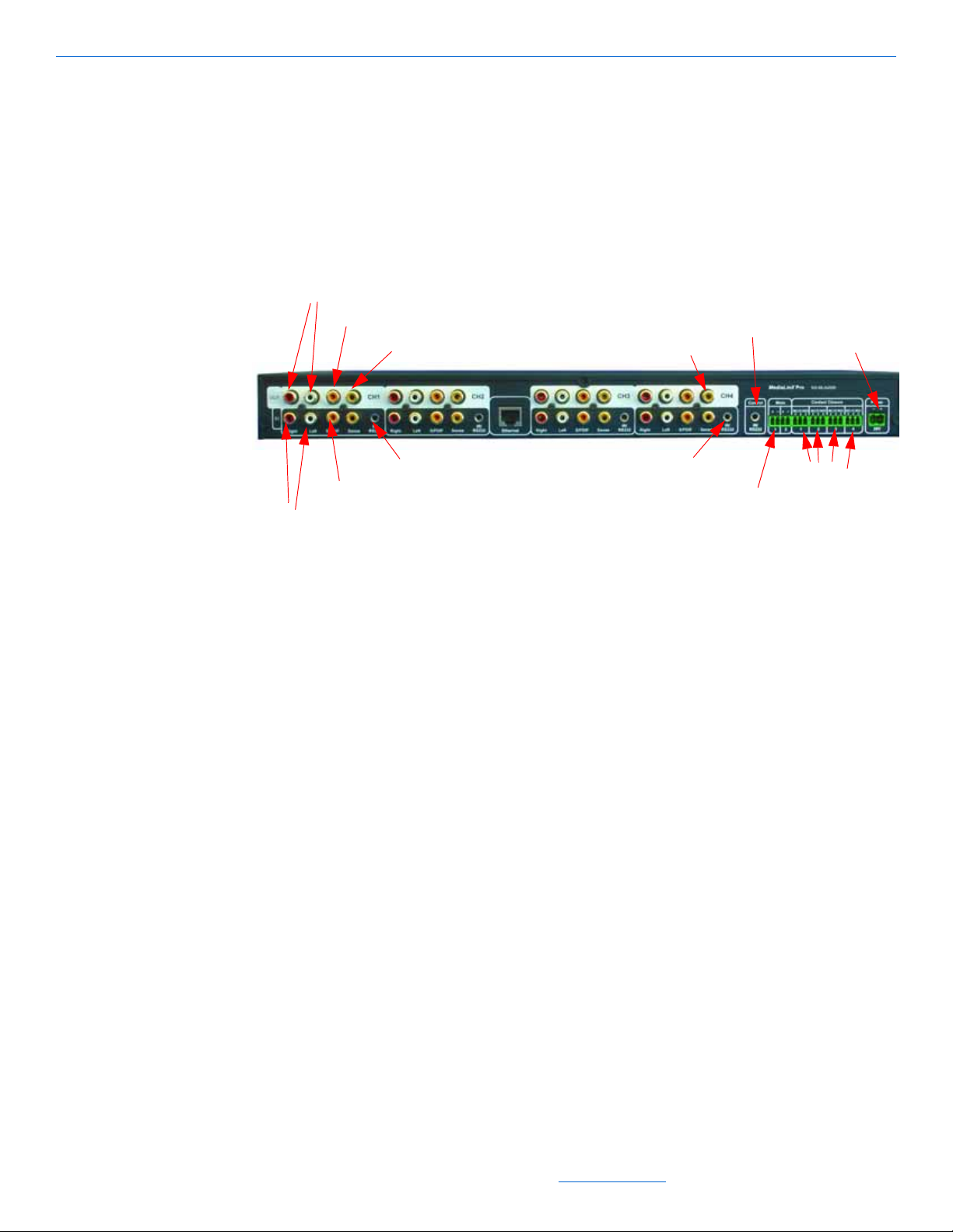
MediaLinX Pro MLA4000
Analog Audio Out
Power
IR/RS-232
IR/RS-232
Mute Interface
Digital Audio Ou
t
Power Sensor
Input Sensor
Analog Audio In
Digital Audio In
Digital Audio In
Contact Closures
IR/RS-232
Figure 5-3 shows the rear panel of the MLA4000. The rear panel has five channels. For
illustration purposes, a MediaLinX is shown in channel 1 (the far left) and a
ControLinX is shown in channel 4. However, channels 1, 2, 3 and 4 can be MediaLinX
or ControLinX in DigiLinX Dealer Setup depending on your particular configuration.
Channel 5 (the far right) is always a dedicated ControLinX.
MediaLinX
Specifications
Figure 5-3 MLA4000 Rear Panel
The MediaLinX MLA4000 has the following specifications:
Real-time conversion of up to 4 stereo, digital, or analog audio sources to TCP/IP
uncompressed audio streams
Burr-Brown
RCA and S/PDIF inputs and outputs for connection flexibility and pass-through
Power management sensor for video, LED, or level sensing of audio sources for
®
24-bit/96kHz Analog-to-Digital Converters
audio playback
Integrated IR receiver for IR learning
Plug and play integration of:
Lutron
AprilAire
GE
Vantage
Panorama
®
lighting systems
®
HVAC system
®
security systems
™
lighting systems
Doorbell mute Interface
IR-Controlled devices
RS-232 controlled devices
All specifications subject to change without notification. All rights reserved. Copyright © 2008 NetStreams
Main +1 512.977-9393 / fax +1 512.977.9398 / Toll Free Technical Support +1 866-353-3496
3600 W. Parmer Lane, Suite 100; Austin, TX 78727 / www.netstreams.com.
5-5
Page 45

DigiLinX Installation and Design Guide
LEDs for signal detection, power detection, and activity status
Dimensions 17.25” wide x 1.75” high x 9.25” deep (438mm x 44mm x 235mm)
Weight 5.44 lb. (2.47 kg)
NetPower: 2
Five 3.5mm to RS-232 cables (included).
Connectors
The MediaLinX Pro has the following connectors:
audio input connectors: four gold-plated RCA jacks
audio output connectors: four gold-plated RCA jacks, four coaxial digital (S/PDIF)
RJ45 connector
four power sensing RCA inputs
composite video passthrough
four 3.5mm IR emitter outputs/RS-232 outputs
four contact closures
doorbell mute interface.
Installation
The MediaLinX MLA4000 can be rack mounted or it can function as a standalone
device.
Installing a MediaLinX MLA4000 in a Rack
The MediaLinX MLA4000 can be mounted using rack ears. To install a MediaLinX
MLA4000, complete these steps:
1. Screw the rack mount ears into the MLA4000.
2. Slide the MLA4000 into the rack.
3. Screw the rack ears into the rack.
For a MediaLinX:
4. Connect all legacy sources.
5. Connect Ethernet.
6. Connect power.
For a ControLinX:
7. Configure the third-party system using the manufacturer’s instructions.
5-6
8. Connect the IR emitter or RS-232 connector to the third party device.
9. Connect a 16/2 cable from the power port of the ControLinX to a PowerLinX.
10. Connect a CAT5 Ethernet cable from the ControLinX to a SwitchLinX.
All specifications subject to change without notification. All rights reserved. Copyright © 2008 NetStreams
Main +1 512.977-9393 / fax +1 512.977.9398 / Toll Free Technical Support +1 866-353-3496
3600 W. Parmer Lane, Suite 100; Austin, TX 78727 / www.netstreams.com.
Page 46

Installing a Free Standing MediaLinX MLA4000
IR/RS232 In/
Out
Analog
Audio
S/PDIF
Sense
S-Video
Component
Contact
Closures
VGA
Ethernet
Power
The MediaLinX MLA4000 can be installed in a free standing environment. Complete
the following steps:
For a MediaLinX:
1. Connect all legacy sources.
2. Connect Ethernet.
3. Connect power.
For a ControLinX:
4. Configure the third-party system using the manufacturer’s instructions.
5. Connect the IR emitter or RS-232 connector to the third party device.
6. Connect a 16/2 cable from the power port of the ControLinX to a PowerLinX.
7. Connect a CAT5 Ethernet cable from the ControLinX to a SwitchLinX.
MediaLinX A/V MLAV300
MediaLinX
Figure 5-4 shows the rear panel of the MediaLinX A/V 300 rear panel. The input
connectors are located on the bottom. The pass-through connectors are located at the
top.
Figure 5-4 MediaLinX A/V 300 rear panel
NOTE: The MLAV300 does not ship with a power supply. We recommend connecting the
power to a PowerLinX PL600 or PL140.
Specifications
All specifications subject to change without notification. All rights reserved. Copyright © 2008 NetStreams
Distribute uncompressed HD Video and surround sound over a TCP/IP network
Main +1 512.977-9393 / fax +1 512.977.9398 / Toll Free Technical Support +1 866-353-3496
3600 W. Parmer Lane, Suite 100; Austin, TX 78727 / www.netstreams.com.
5-7
Page 47

DigiLinX Installation and Design Guide
Real-time conversion of one component, composite, S-Video or VGA video signal,
and one stereo analog and digital S/PDIF audio signal from a video source into
TCP/IP uncompressed audio/video streams
480i format conversion across: Composite to S-Video, S-Video to Component or
vice versa
BURR-BROWN 24-bit/96KHz Analog-to-Digital converters
Power management sensor for Video, LED, or Level sensing of video sources for
audio playback
Integrated IR receiver
IR/RS-232 (two way) control of sources (cable included)
Includes three contact closures - two function as output contact closures and one
functions as a circuit closure detector
NTSC and PAL capable
LEDs for Signal detection, Power detection, and Activity status
Power State Sense Input
Dimensions: 9 1/2” high x 1 3/4” high x 8 2/3” deep (24mm x 45mm x 240mm)
Weight: 4 lbs (2.722 Kg)
NetPower: 4
ROHS compliant
Connectors
Video Input/Output Connectors Composite Input and pass-through (480i, 576i)
Audio Input Connectors One pair of analog RCA jacks (Gold Plated)
Audio Output Connectors One pair of analog RCA jacks (Gold Plated)
Gigabit Ethernet Connection RJ45
2-position Phoenix Connector - power20 - 32VDC
IR Emitter output/RS232 One 3.5mm
S-video Input and pass-through (480i, 576i)
Component Input and pass-through (480i, 480p,
720p, 1080i)
VGA Input (up to 1024 x 768 @ 60Hz)
One Coaxial Digital (S/PDIF) (Gold Plated)
One Coaxial Digital (S/PDIF) (Gold Plated)
5-8
IR Receiver input One included
3 Contact Closures One input, Two output
All specifications subject to change without notification. All rights reserved. Copyright © 2008 NetStreams
Main +1 512.977-9393 / fax +1 512.977.9398 / Toll Free Technical Support +1 866-353-3496
3600 W. Parmer Lane, Suite 100; Austin, TX 78727 / www.netstreams.com.
Page 48

Installation
Power
Ethernet
RGBHV + Component
Sense
Digital Audio Input
Analog Audio In
Relay
Balanced Audio In
RS-232
The MediaLinX A/V is a half-rack width, 1U high device. Use a RS1U rack shelf to fit
two MediaLinX A/Vs per shelf. To fit only one MediaLinX A/V, use the blank plate
provided with the RS1U. Screws are included to screw the rack mounted device on the
rack shelf.
Depending on its use, connect S/PDIF, component, composite, VGA, or S-Video. If
you are connecting it to a PC, you would use the VGA connection. Be sure to connect
both Analog Audio and S/PDIF. Connect the Ethernet CAT5 cable to the Ethernet port.
Connect the power cable to the Power port.
MediaLinX A/V MLAV9300-CS
Figure 5-4 shows the rear panel of the MediaLinX A/V 300 rear panel. The input
connectors are located on the bottom. The pass-through connectors are located at the
top.
MediaLinX
Figure 5-5 MediaLinX A/V 9300-CS rear panel
NOTE: The MLAV9300-CS does not ship with a power supply. We recommend connecting
the power to a PowerLinX PL600 or PL140.
Specifications
Distribute uncompressed or MotionXT compressed HD Video and surround sound
over a TCP/IP network
Real-time conversion of one component, composite, S-Video or RGBHV video
signal, and one stereo analog and digital S/PDIF audio signal from a video source
into TCP/IP uncompressed audio/video streams
480i format conversion across: Composite to S-Video, S-Video to Component or
All specifications subject to change without notification. All rights reserved. Copyright © 2008 NetStreams
vice versa
Main +1 512.977-9393 / fax +1 512.977.9398 / Toll Free Technical Support +1 866-353-3496
3600 W. Parmer Lane, Suite 100; Austin, TX 78727 / www.netstreams.com.
5-9
Page 49

DigiLinX Installation and Design Guide
BURR-BROWN 24-bit/96KHz Analog-to-Digital converters
Power management sensor for Video, LED, or Level sensing of video sources for
audio playback
Balanced Audio Input - Phoenix Connectors
Integrated IR receiver
IR/RS-232 (two way) control of sources (cable included)
Includes three contact closures - two function as output contact closures and one
functions as a circuit closure detector
NTSC and PAL capable
LEDs for Signal detection, Power detection, and Activity status
Power State Sense Input
Dimensions: 9 1/2” high x 1 3/4” high x 8 2/3” deep (24mm x 45mm x 240mm)
Weight: 4 lbs (2.722 Kg)
NetPower: 4
ROHS compliant
Connectors
Video Input/Output Connectors Video Connectors are BNC
Audio Input Connectors One pair of analog RCA jacks (Gold Plated)
Audio Output Connectors One pair of analog RCA jacks (Gold Plated)
Gigabit Ethernet Connection RJ45
2-position Phoenix Connector - power20 - 32VDC
IR Emitter output/RS232 One 3.5mm
IR Receiver input One included
3 Contact Closures One input, Two output
Composite Input and pass-through (480i, 576i)
S-video Input and pass-through (480i, 576i)
Component Input and pass-through (480i, 480p,
720p, 1080i)
RGBHV Input (up to 1024 x 768 @ 60Hz)
One Coaxial Digital (S/PDIF) (Gold Plated)
3-Position Phoenix Connectors - Balanced Audio
One Coaxial Digital (S/PDIF) (Gold Plated)
5-10
Installation
The MediaLinX A/V is a half-rack width, 1U high device. Use a RS1U rack shelf to fit
two MediaLinX A/Vs per shelf. To fit only one MediaLinX A/V, use the blank plate
All specifications subject to change without notification. All rights reserved. Copyright © 2008 NetStreams
Main +1 512.977-9393 / fax +1 512.977.9398 / Toll Free Technical Support +1 866-353-3496
3600 W. Parmer Lane, Suite 100; Austin, TX 78727 / www.netstreams.com.
Page 50

provided with the RS1U. Screws are included to screw the rack mounted device on the
rack shelf.
Depending on its use, connect S/PDIF, component, composite, RGBHV, or S-Video. If
you are connecting it to a PC, you would use the VGA to BNC adapter for the
connection. Be sure to connect both Analog Audio and S/PDIF. Connect the Ethernet
CAT5 cable to the Ethernet port. Connect the power cable to the Power port.
Programming IR Codes
To program IR codes into the MediaLinX, refer to Chapter 5 in the DigiLinX Dealer
Setup Manual located on the Dealer Documents page on the NetStreams web site.
MediaLinX
5-11
All specifications subject to change without notification. All rights reserved. Copyright © 2008 NetStreams
Main +1 512.977-9393 / fax +1 512.977.9398 / Toll Free Technical Support +1 866-353-3496
3600 W. Parmer Lane, Suite 100; Austin, TX 78727 / www.netstreams.com.
Page 51

DigiLinX Installation and Design Guide
5-12
All specifications subject to change without notification. All rights reserved. Copyright © 2008 NetStreams
Main +1 512.977-9393 / fax +1 512.977.9398 / Toll Free Technical Support +1 866-353-3496
3600 W. Parmer Lane, Suite 100; Austin, TX 78727 / www.netstreams.com.
Page 52

Chapter
6
TouchLinX
TouchLinX TL380 is a 3.8-inch, high-resolution Thin Film Transistor (TFT) touch
screen controller that runs the Windows® CE operating system. TouchLinX TL430
and TL700 also run the Windows CE operating system, and have 4.3-inch and 7-inch
®
screens, respectively. All TouchLinX models feature built-in Adobe
deliver a dynamically-generated, highly interactive user interface. Four laser-etched
hard key buttons provide control for power, mute, and volume while the interactive
LCD touch screen displays contextual buttons for the selected source.
A microphone is included in the keypad for IP intercom.
Flash® and
Figure 6-1 TL380
All specifications subject to change without notification. All rights reserved. Copyright © 2008 NetStreams
Main +1 512.977-9393 / fax +1 512.977.9398 / Toll Free Technical Support +1 866-353-3496
3600 W. Parmer Lane, Suite 100; Austin, TX 78727 / www.netstreams.com.
6-1
Page 53

DigiLinX Installation and Design Guide
Figure 6-2 TL430
6-2
Figure 6-3 TL700
TL380 Specifications
The following are the specifications for a TouchLinX TL380:
Built-in four-port Ethernet switch
Fits standard two-gang box
Operating system: Windows CE 4.2
Faceplates: white, almond, ivory, black, and titanium
In wall dimensions:
3 5/8” wide x 2 13/16” high x 2” deep (98mm x 72mm x 45mm)
All specifications subject to change without notification. All rights reserved. Copyright © 2008 NetStreams
Main +1 512.977-9393 / fax +1 512.977.9398 / Toll Free Technical Support +1 866-353-3496
3600 W. Parmer Lane, Suite 100; Austin, TX 78727 / www.netstreams.com.
Page 54

External dimensions:
4 9/16” high x 4 5/8” wide x 2” deep (114mm x 116mm x 50mm)
Weight:
0.5 lbs (0.23 Kg)
NetPower: 1
TL430 Specifications
Connectors:
Two Ethernet RJ45 (EIA 568a)
Two 4-pin Phoenix connectors (28V power)
Embedded Adobe
Operating system: Windows
Built-in 2-port Ethernet switch
Built-in microphone for intercom, paging, and zone monitoring
Resolution: 480x272
Viewing angle: 65
®
Flash Player
o
horizontal, 80o vertical
®
®
CE 5.0
TouchLinX
In wall dimensions:
4 3/4” wide x 3 3/16” high x 1 1/4” deep (120mm x 97mm x 322mm)
External dimensions:
5 1/2” high x 4 5/8” wide 1 9/16” deep (140mm x 117mm x 39.7mm)
Weight: 0.8 lbs. (.0.363 Kg)
NetPower: 1
Faceplates: white, ivory, black, almond.
TL700 Specifications
Connectors:
Two Ethernet RJ45 (EIA 568a)
Two 4-pin Phoenix connectors (28V power)
Embedded Adobe
Operating system: Windows
Built-in 2-port Ethernet switch
Built-in microphone for intercom, paging, and zone monitoring
Resolution: 800x480
Viewing angle: 65
®
Flash Player
o
horizontal, 50o vertical
®
®
CE 5.0
In wall dimensions:
7 1/16” wide, 4 15/16” high, 1 1/4” deep (180mm x 126mm x 32.2mm)
6-3
All specifications subject to change without notification. All rights reserved. Copyright © 2008 NetStreams
Main +1 512.977-9393 / fax +1 512.977.9398 / Toll Free Technical Support +1 866-353-3496
3600 W. Parmer Lane, Suite 100; Austin, TX 78727 / www.netstreams.com.
Page 55

DigiLinX Installation and Design Guide
External dimensions:
7 7/8” high x 4 15/16” wide x 1 9/16” deep (200mm x 146mm x 39.7mm)
Weight: 1 lb., 6 oz. (0.612 Kg)
NetPower: 1
Faceplates: white, ivory, black, almond.
Connectors
The following connectors are on a TouchLinX:
Ethernet: two (TL430 and TL700) or four (TL380) RJ45 ports.
power input: four-pin Phoenix connector (included)
power output: four-pin Phoenix connector (included).
TL380 Installation
To install a TouchLinX TL 380 into a wall, complete the following steps:
1. Install a double-gang backless box into a wall. (TL380 only)
2. Make all connections to the device.
3. Mount the device in the box.
4. Turn power on to the device.
5. Refer to the DigiLinX Dealer Setup Manual located on the Dealer Documents page
on the NetStreams web site to configure the device.
NOTE:A white, screwless faceplate is included. Ivory, Almond, and Black color kits are sold
separately.
6. Snap the screwless faceplate onto the cover.
TL430/TL700 Installation
To install a TouchLinX TL430 or TL700, complete the following steps.
1. Use the included template to mark the wall and cut the hole for the TouchLinX.
NOTE: The tolerance between the edge of the template and the edge of the TouchLinX is
about 1cm. Measure twice, cut once.
6-4
2. Make all connections to the device.
3. Insert the TouchLinX into the hole.
All specifications subject to change without notification. All rights reserved. Copyright © 2008 NetStreams
Main +1 512.977-9393 / fax +1 512.977.9398 / Toll Free Technical Support +1 866-353-3496
3600 W. Parmer Lane, Suite 100; Austin, TX 78727 / www.netstreams.com.
Page 56

4. Screw the mounting screws at the top right and bottom left until the butterfly tabs
catch on the inside of the wall.
NOTE: For thicker walls back out the butterfly tabs before inserting the TouchLinX into the
wall to give them room to grab.
5. Snap on the magnetic face plate.
Installation of a TL430/TL700 in a Rough-In Box
For instructions on installing a TL430/TL700 in a rough-in box, refer to the Dealer
section of the NetStreams web site and see Technical Bulletin 040031 - Installing a
TL430 or TL700 in a Rough-In Box.
TouchLinX
6-5
All specifications subject to change without notification. All rights reserved. Copyright © 2008 NetStreams
Main +1 512.977-9393 / fax +1 512.977.9398 / Toll Free Technical Support +1 866-353-3496
3600 W. Parmer Lane, Suite 100; Austin, TX 78727 / www.netstreams.com.
Page 57

DigiLinX Installation and Design Guide
6-6
All specifications subject to change without notification. All rights reserved. Copyright © 2008 NetStreams
Main +1 512.977-9393 / fax +1 512.977.9398 / Toll Free Technical Support +1 866-353-3496
3600 W. Parmer Lane, Suite 100; Austin, TX 78727 / www.netstreams.com.
Page 58

Chapter
KL101
KL201
Back
7
KeyLinX
KeyLinX KL100/KL101 and KL200/KL201 are single-gang, in-wall keypads that
control up to four sources (see Figure 7-1). The KL201 also features:
an integrated microphone
a Do Not Disturb LED
a Talk button for IP intercom.
Figure 7-1 KeyLinX
NOTE:The only difference between the KL100 and KL101 and the KL200 and KL201 are that
the KL101 and KL201 models are compliant with the European Reduction of Hazardous
Substances (RoHS) directive and have an IRLinX EIM port connector on the rear.
All specifications subject to change without notification. All rights reserved. Copyright © 2008 NetStreams
Main +1 512.977-9393 / fax +1 512.977.9398 / Toll Free Technical Support +1 866-353-3496
3600 W. Parmer Lane, Suite 100; Austin, TX 78727 / www.netstreams.com.
7-1
Page 59

DigiLinX Installation and Design Guide
IMPORTANT! Both the KL100/KL101 and KL200/KL201ship with an Expansion
Interface Module (EIM) splitter . This EIM splitter must be used when installing both a
KeyLinX and an Audio Port or MU290 power amplifier.
KeyLinX are perfect for smaller rooms that do not require a touchscreen. The
KeyLinX models feature up to six presets for each one of the four audio sources. These
presets are programmed from the DigiLinX Dealer Setup Program and are accessible
by pressing and holding the corresponding key on the KeyLinX for two seconds.
Specifications
Two RJ-45 connectors (EIM)
Fits in standard single-gang box
Green LEDs for volume status
IR Receiver
Built-in microphone
Connectors
Installation
Ten laser-etched hard key buttons
Faceplate: white, almond, ivory, or black
In-wall dimensions: 1 3/4” wide x 2 13/16” high x 1 1/4” deep (45mm x 71mm x
32mm)
External dimensions: 2 3/4” wide x 4 5/8” high x 1 1/2” deep (69mm x 117mm x
38mm)
Weight: 4.9 oz. (139 grams)
NetPower: 1.
The KeyLinX has two RJ45 connectors.
To install a KeyLinX, complete procedures in the following sections.
7-2
Installing in a Wall
To install a KeyLinX into a wall, complete the following steps:
1. Install a single-gang backless box into a wall.
2. Make all connections to the device.
3. Mount the device in the box.
All specifications subject to change without notification. All rights reserved. Copyright © 2008 NetStreams
Main +1 512.977-9393 / fax +1 512.977.9398 / Toll Free Technical Support +1 866-353-3496
3600 W. Parmer Lane, Suite 100; Austin, TX 78727 / www.netstreams.com.
Page 60

4. Turn on power to the SpeakerLinX that the KeyLinX is connected to.
NOTE: A white screwless faceplate is included. Others are sold separately.
5. Refer to the DigiLinX Dealer Setup Manual located on the Dealer Documents page
on the NetStreams web site to configure the device.
6. Snap the screwless faceplate onto the cover.
Installing an EIM Splitter in a KeyLinX Configuration
The EIM splitter is required in all KeyLinX and IRLinX installations. This provides a
port for the KeyLinX (KL101 or KL201) and for the Audio Port. Figure 7-1 shows a
KeyLinX configuration using an EIM splitter, SpeakerLinX, SwitchLinX, MU290,
Audio Port, and IRLinX.
Note that in the following configuration, an IRLinX can be used with a KeyLinX
(KL101or KL201) to position an IR receiver in a more convenient location.
KeyLinX
7-3
All specifications subject to change without notification. All rights reserved. Copyright © 2008 NetStreams
Main +1 512.977-9393 / fax +1 512.977.9398 / Toll Free Technical Support +1 866-353-3496
3600 W. Parmer Lane, Suite 100; Austin, TX 78727 / www.netstreams.com.
Page 61

DigiLinX Installation and Design Guide
Legend
CAT5
KL1R
IMPORTANT! The cable and EIM splitter are located under the cardboard bottom in
the KeyLinX box.
7-4
Figure 7-1 KeyLinX Configuration
NOTE:Maximum CAT5 cable length for EIM connections is 60 feet.
To connect the KeyLinX configuration shown in the figure above, follow these steps:
1. Locate the cable and splitter under the cardboard located at the bottom of the Key-
LinX box.
2. Connect the SpeakerLinX to the EIM splitter connector labeled SpeakerLinX using
the 1 foot cable provided.
3. Connect the KeyLinX to the EIM splitter jack labeled KeyLinX.
All specifications subject to change without notification. All rights reserved. Copyright © 2008 NetStreams
Main +1 512.977-9393 / fax +1 512.977.9398 / Toll Free Technical Support +1 866-353-3496
3600 W. Parmer Lane, Suite 100; Austin, TX 78727 / www.netstreams.com.
Page 62

KeyLinX
4. Connect the Audio Port or MU290 to the EIM splitter jack labeled Audio.
5. Connect the IRLinX to the KeyLinX connector labeled IRLinX.
6. Run a CAT5 cable from the KeyLinX port on the EIM splitter to the KeyLinX.
7. From the Audio port located on the EIM splitter, run a CAT5 cable to the Audio
Port (or to the MU290 and then to the Audio Port if you are using an MU290).
7-5
All specifications subject to change without notification. All rights reserved. Copyright © 2008 NetStreams
Main +1 512.977-9393 / fax +1 512.977.9398 / Toll Free Technical Support +1 866-353-3496
3600 W. Parmer Lane, Suite 100; Austin, TX 78727 / www.netstreams.com.
Page 63

DigiLinX Installation and Design Guide
7-6
All specifications subject to change without notification. All rights reserved. Copyright © 2008 NetStreams
Main +1 512.977-9393 / fax +1 512.977.9398 / Toll Free Technical Support +1 866-353-3496
3600 W. Parmer Lane, Suite 100; Austin, TX 78727 / www.netstreams.com.
Page 64

Chapter
CL9100-CS - Commercial Series ControLinX
8
ControLinX
The ControLinX CL100/CL9100-CS enables the control of non IP-Based sources
from the DigiLinX Multi-Room Audio and Control system. Control is through RS-
232, one-way IR, or voltage sensing.
The ControLinX CL100 includes but is not limited to NetStreams-written two-way
drivers for:
Lutron
Lutron HomeWorks
Aprilaire
®
RadioRA® lighting system
®
lighting system
®
HVAC system
Panorama
GE
Vantage
custom two-way drivers.
®
Concord™ security system
™
lighting systems
ControLinX is not limited to these systems. You can control other systems using one
of the following:
one-way RS-232
one-way IR
two-way RS-232 using a custom driver written for NetStreams’ Control
Application Programming Interface (API).
All specifications subject to change without notification. All rights reserved. Copyright © 2008 NetStreams
Main +1 512.977-9393 / fax +1 512.977.9398 / Toll Free Technical Support +1 866-353-3496
3600 W. Parmer Lane, Suite 100; Austin, TX 78727 / www.netstreams.com.
8-1
Page 65

DigiLinX Installation and Design Guide
Specifications
Drivers included
Voltage sensor with pentiometer for adjustment
LEDs for IR and voltage sensing detection
Dimensions: 4 6/10” wide x 3 1/5” high x 1 6/10” deep (120mm x 89mm x 40mm)
(CL100); 9 1/2” wide x 1 3/4” high x 8 2/3” deep (244mm x 45mm x 220mm)
(CL9100-CS)
Weight: 1 lb. (0.6 kg) (CL100);3.25lbs (1.47kg) (CL9100-CS)
NetPower: 1.
Connectors
The following are connectors for the ControLinX:
Ethernet: one RJ45 connector
power input: two-pin Phoenix connector (included)
Installation
IR/RS-232: 3.5mm IR emitter (cable included) or 3.5mm to RS-232 (cable
included)
RCA input: for voltage trigger sensing (use an RCA to two-tinned lead cable - sold
separately).
Figure 8-1 shows how to install a ControLinX. To install a ControLinX, complete the
following steps:
1. Configure the third-party system using the manufacturer’s instructions.
2. Connect the IR emitter or RS-232 connector to the third party device.
3. Connect a 16/2 cable from the power port of the ControLinX to a PowerLinX.
4. The ControLinX CL-9100-CS can be rack mounted using the included rack mount
ears.
8-2
All specifications subject to change without notification. All rights reserved. Copyright © 2008 NetStreams
Main +1 512.977-9393 / fax +1 512.977.9398 / Toll Free Technical Support +1 866-353-3496
3600 W. Parmer Lane, Suite 100; Austin, TX 78727 / www.netstreams.com.
Page 66

5. Connect a CAT5 Ethernet cable from the ControLinX to a SwitchLinX.
ControLinX
Figure 8-1 Installing ControLinX
8-
3
All specifications subject to change without notification. All rights reserved. Copyright © 2008 NetStreams
Main +1 512.977-9393 / fax +1 512.977.9398 / Toll Free Technical Support +1 866-353-3496
Page 67

DigiLinX Installation and Design Guide
8-4
All specifications subject to change without notification. All rights reserved. Copyright © 2008 NetStreams
Main +1 512.977-9393 / fax +1 512.977.9398 / Toll Free Technical Support +1 866-353-3496
3600 W. Parmer Lane, Suite 100; Austin, TX 78727 / www.netstreams.com.
Page 68

Chapter
9
PowerLinX
The PowerLinX distributes power to DigiLinX products. It is a tightly-regulated
power supply with built-in intelligence to indicate over-currents or failures. There are
several models of PowerLinX:
PL750/PL751 - The high powered PowerLinX PL750/PL751 is required for
installations with SpeakerLinX SL250s and is designed to distribute up to 27A @
28VDC of power to multiple DigiLinX products on an IP-Based Multi-Room
Audio network. Additional PowerLinX power supplies may be required as the
DigiLinX system is scaled in size. Note that a PL750/PL751 is required when
installing an SL250.
PL600 - PowerLinX is an intelligent power supply that is designed to distribute up
PL250 - 100 Watt PowerLinX Plug-in Power Supply designed to power one SL250
NOTE: PL228 and PL600 are not for use with the SL250.
PL228 - 80 Watt PowerLinX Power Supply designed to power one SpeakerLinX
PL750/PL751
The following are specifications for the PL750/PL751:
27A /28VDC Intelligent Power Supply (7A max from any one output connector)
to 21A @ 28VDC of power to multiple DigiLinX products on an IP-Based MultiRoom Audio network. This tightly-regulated power supply is essential for a
DigiLinX IP-Based Multi-Room Audio system, with additional PowerLinX power
supplies required as the number of nodes on the network increases. The PL600
features over current protection and LEDs for current feedback. Available in
120VAC and 240VAC.
SpeakerLinX and one TouchLinX touch screen.
SL220, MediaLinX, ControLinX, or TouchLinX, the PowerLinX PL228 local
power supply is the perfect solution for retrofit installations.
8.5A /115 VAC Input (constant power supply)
8 discrete output channels of power at 28VDC
dual-color status LEDs
All specifications subject to change without notification. All rights reserved. Copyright © 2008 NetStreams
Main +1 512.977-9393 / fax +1 512.977.9398 / Toll Free Technical Support +1 866-353-3496
3600 W. Parmer Lane, Suite 100; Austin, TX 78727 / www.netstreams.com.
9-1
Page 69

DigiLinX Installation and Design Guide
Power
Switch
IEC Power
Connector
(for AC)
8 x 5.5mm removable Phoenix connectors
1 IEC power cord UL, CE, and FCC Certified
optional Rack Shelf for rack mounting up to 3 PowerLinX (sold separately)
overload protection: 105%~125% of rated output per output connector: 4.5A
dimensions: 5 4/5” wide x 3 1/2” high x 14 1/3” deep (147mm x 86mm x 363mm)
weight: 9 lbs (4.1 kgs)
NetPower: 168.
See Figure 9-1 for an example of the PL750/PL751 rear panel.
PL600
Figure 9-1 PowerLinX PL750/PL751
NOTE: The PL750/751 is known to generate high levels of noise. Please select a location with
this in mind.
The following are specifications for the PL600:
21A /28VDC Intelligent Power Supply (4.5A max from any one output connector)
12A /115 VAC Input (inrush 30A current)
eight discrete output channels of power at 28VDC
dual-color status LEDs
8 x 5.5mm removable Phoenix connectors
1 IEC power cord UL, CE, and FCC Certified
optional Rack Shelf for rack mounting up to 3 PowerLinX (sold separately)
overload protection: 105%~125% of rated output per output connector: 4.5A
dimensions: 5 4/5” wide x 3 1/2” high x 14 1/3” deep (147mm x 86mm x 363mm)
weight: 9 lbs (4.1 kgs)
NetPower: 84.
9-2
All specifications subject to change without notification. All rights reserved. Copyright © 2008 NetStreams
Main +1 512.977-9393 / fax +1 512.977.9398 / Toll Free Technical Support +1 866-353-3496
3600 W. Parmer Lane, Suite 100; Austin, TX 78727 / www.netstreams.com.
Page 70

PL250
Power
Switch
IEC Power
Connector
(for AC)
IEC Power
Connector
(for AC)
Power
Switch
PowerLinX
See Figure 9-2 for an example of the PL600 rear panel.
Figure 9-2 PowerLinX PL600
Specifications for the PL250 include:
120/240 VAC 50/60 Hz input
100 Watts of output at 28VDC
CE, C-Tick, and RoHS compliant.
See Figure 9-3 for an example of the PL250 rear panel.
PL228
Figure 9-3 PowerLinX PL250
Specifications for the PL228 include:
120/240 VAC 50/60 Hz input
All specifications subject to change without notification. All rights reserved. Copyright © 2008 NetStreams
Main +1 512.977-9393 / fax +1 512.977.9398 / Toll Free Technical Support +1 866-353-3496
3600 W. Parmer Lane, Suite 100; Austin, TX 78727 / www.netstreams.com.
9-3
Page 71

DigiLinX Installation and Design Guide
80 Watts at 28VDC
power LED
IEC power cord
CE, C-Tick, and RoHS compliant.
See Figure 9-4 for an example of the PL228.
Installation
Installing a PowerLinX PL600 or PL750
Figure 9-4 PowerLinX PL228
This section discusses the installation of all PowerLinX devices.
This section discusses installation of the PowerLinX PL600 or PL750 in either a rack
or a free standing environment. Refer to Table 9-1 for the maximum number of
SL220s or SL250s for the PL600 or PL750.
Table 9-1 Maximum Number of SL220s or SL250s per
PowerLinX PL600 or PL750
PowerLinX Model Maximum
SL220s
PL600 6 0
PL750 1 2 6
Maximum
SL250s
9-4
Installing in a Rack
To install a PL600 or PL750 into a rack, complete the following steps:
1. Install the PL51 plate (sold separately) into the rack.
All specifications subject to change without notification. All rights reserved. Copyright © 2008 NetStreams
Main +1 512.977-9393 / fax +1 512.977.9398 / Toll Free Technical Support +1 866-353-3496
3600 W. Parmer Lane, Suite 100; Austin, TX 78727 / www.netstreams.com.
Page 72

2. Place the PowerLinX on the PL50/PL51.
NOTE: If only one PowerLinX is being used, then two blank faceplates are needed to cover
the open spaces. The PL51 comes with two blank faceplates.
3. Install the PL10 blank plate to cover any open spaces.
4. Terminate all power wires to the Phoenix connectors (ensure polarity is correct).
5. Plug the PowerLinX into the AC outlet.
Note that a minimum of six SpeakerLinX can be used on each power supply with a
maximum of one SpeakerLinX per port. This leaves two extra ports for other devices.
Installing Free Standing
1. Terminate all power wires to the Phoenix connectors (ensure polarity is correct).
NOTE: To avoid heat build-up, ensure all electronics have a minimum of 1 cubic ft. of air
space.
2. Plug the PowerLinX into the AC outlet.
PowerLinX
LED Indicators
The LEDs on the PL600 and PL750 front panel indicate status for each of the eight
power connections on the unit. These LEDs identify any problems with power from the
PowerLinX. The following are the indications used:
Green Active/OK
Amber Potential Current Overdraw
Red Current Overdraw.
Installing a PL250 or PL228
To install the PL250 or PL228, complete the following steps:
NOTE: Ensure the polarity is correct. Look on the bottom of the PowerLinX to determine
which wire is negative and which is positive.
1. Attach a two-pin Phoenix connector to the cable from the PL250 or PL228.
2. Plug it into a SpeakerLinX, ControLinX, MediaLinX, or TouchLinX.
3. Turn on the PL250 or PL228.
9-5
All specifications subject to change without notification. All rights reserved. Copyright © 2008 NetStreams
Main +1 512.977-9393 / fax +1 512.977.9398 / Toll Free Technical Support +1 866-353-3496
3600 W. Parmer Lane, Suite 100; Austin, TX 78727 / www.netstreams.com.
Page 73

DigiLinX Installation and Design Guide
9-6
All specifications subject to change without notification. All rights reserved. Copyright © 2008 NetStreams
Main +1 512.977-9393 / fax +1 512.977.9398 / Toll Free Technical Support +1 866-353-3496
3600 W. Parmer Lane, Suite 100; Austin, TX 78727 / www.netstreams.com.
Page 74

SW324
Chapter
10
SwitchLinX
SwitchLinX is a family of Internet Group Management Protocol (IGMP)-enabled,
multicasting, non-blocking 10/100 and 10/100/1000 Mbps Fast Ethernet switches
designed for handling the high demands of networked audio/video distribution
products. Additional SwitchLinX devices can be used to expand the network. There
are four models of SwitchLinX: SW324, SW208, SW1024, and SW1048.
The following are specifications for the SW324:
technology store and forward architecture, non-blocking
IP multicast supports IGMP snooping
IGMP querier devices
Up to 256 multicast groups
standards: IEEE 802.3 10Base-T Ethernet
IEEE 802.3u 100Base-TX
100Base-FX Fast Ethernet
filtering address: Unicast/Multicast/Broadcast
filtering rate: 14,880 pps for Ethernet; 148,800 pps for Fast Ethernet
forwarding rate: 14,880 pps for Ethernet; 148,800 pps for Fast Ethernet
connector: RJ45 jack
LED indicators: Link/Activity, Full Duplex/Collision status for each port
environment operating temperature: 0º C to 50º, storage -40º to 70º C
dimensions: 17 3/10" wide x 6 5/8" high x 1 7/10" deep (440mm x 172mm x
43mm).
SW208
The following are specifications for the SW208:
technology store and forward architecture, non-blocking
10-1
All specifications subject to change without notification. All rights reserved. Copyright © 2008 NetStreams
Main +1 512.977-9393 / fax +1 512.977.9398 / Toll Free Technical Support +1 866-353-3496
3600 W. Parmer Lane, Suite 100; Austin, TX 78727 / www.netstreams.com.
Page 75

DigiLinX Installation and Design Guide
IP multicast supports IGMP snooping
Up to 256 multicast groups
standards: IEEE 802.3 10Base-T Ethernet, IEEE 802.3u 100Base-TX, 100Base-FX
Fast Ethernet
filtering address: Unicast/Multicast/Broadcast
filtering rate: 14,880 pps for Ethernet; 148,800 pps for Fast Ethernet
forwarding rate: 14,880 pps for Ethernet; 148,800 pps for Fast Ethernet
connector: RJ45 jack
LED indicators: Link/Activity, Full Duplex/Collision status for each port
environment operating temperature: 0º C to 50º, storage -40º to 70º C
dimensions: 5 1/3" wide x 1 1/2" high x 10" deep (133mm x 37mm x 250mm)
SW1024
NOTE: The SW1024 has a limit of 64 multicast addresses. If you need more addressess, you
will need to add another device.
The following are the specifications for the SW1024:
technology store and forward architecture, non-blocking
IP multicast supports IGMP snooping (64 multicast addresses)
D-Link
48 Gbps switching capacity
24 1Gbps ports
4 combo SFP ports
standards: IEEE 802.3, IEEE 802.3u Fast Ethernet, 802.3ab Gigabit Ethernet,
®
certified, configured by NetStreams
802.3z Gigabit Ethernet, 802.1d Spanning tree, 802.1p priority tags (4 queues),
802.1q VLANS (up to 255), 802.1x Port-Based Authentications, 802.3ad link
aggregation, IAC:SNTP:GVRP support, broadcast storm control, 802.1w Rapid
Spanning Tree, 802.1s Multiple Spanning Tree, Jumbo Grames (9216 bytes), rate
limiting down to 64Kb
Emissions: CE and FCC Class A approved
Power supply, 100-240VAC, 50/60Hz Internal Universal
Power consumption: 30 watts (max)
BTU 15,336/hr
connector: shielded RJ-45 jack
10-2
LED indicators Link/Activity, Full Duplex Collision status for each port
certification: CSA International, FCC Class A, CE Class A. CUL International
All specifications subject to change without notification. All rights reserved. Copyright © 2008 NetStreams
Main +1 512.977-9393 / fax +1 512.977.9398 / Toll Free Technical Support +1 866-353-3496
3600 W. Parmer Lane, Suite 100; Austin, TX 78727 / www.netstreams.com.
Page 76

SwitchLinX
SW1148
environment operating temperature: 0
o
to 40o C (32o to 104o F), storage -10o to 70o
C (14o to 158o F)
humidity: operating: 10% to 90 RH, non-condensing; storage: 0 to 95% RH, non-
condensing)
NetPower: 0
Weight: 7lbs
Dimensions: 12.17” wide x 1.736”high x 1.73” deep (309.1mm x 440.9mm x
43.9mm)
19” rack mountable
The following are the specifications for the SW1148:
technology store and forward architecture, non-blocking
IP multicast supports IGMP snooping (256 multicast addresses)
Dell certified, configured by NetStreams
96 Gbps switching capacity
48 1Gbps ports
4 combo SFP ports
standards: IEEE 802.3, IEEE 802.3u Fast Ethernet, 802.3ab Gigabit Ethernet,
802.3z Gigabit Ethernet, 802.1d Spanning tree, 802.1p priority tags (4 queues),
802.1q VLANS (up to 255), 802.1x Port-Based Authentications, 802.3ad link
aggregation, IAC:SNTP:GVRP support, broadcast storm control, 802.1w Rapid
Spanning Tree, 802.1s Multiple Spanning Tree, Jumbo Grames (9216 bytes), rate
limiting down to 64Kb
Emissions: CE and FCC Class A approved
Power supply, 100-240VAC, 50/60Hz Internal Universal
connector: shielded RJ-45 jack
LED indicators Link/Activity, Full Duplex Collision status for each port
certification: CSA International, FCC Class A, CE Class A. CUL International
environment operating temperature: 0
humidity: operating: 10% to 90 RH, non-condensing;
NetPower: 0
Weight: 3.6Kg
Dimensions: 17.32” wide x 1.73”high x 10.03” deep (440mm x 44mm x 255mm)
o
to 45o C (32o to 113o F)
19” rack mountable
10-3
All specifications subject to change without notification. All rights reserved. Copyright © 2008 NetStreams
Main +1 512.977-9393 / fax +1 512.977.9398 / Toll Free Technical Support +1 866-353-3496
3600 W. Parmer Lane, Suite 100; Austin, TX 78727 / www.netstreams.com.
Page 77

DigiLinX Installation and Design Guide
SW1124
The following are the specifications for the SW1048:
technology store and forward architecture, non-blocking
IP multicast supports IGMP snooping (256 multicast addresses)
Dell certified, configured by NetStreams
96 Gbps switching capacity
24 1Gbps ports
4 combo SFP ports
standards: IEEE 802.3, IEEE 802.3u Fast Ethernet, 802.3ab Gigabit Ethernet,
802.3z Gigabit Ethernet, 802.1d Spanning tree, 802.1p priority tags (4 queues),
802.1q VLANS (up to 255), 802.1x Port-Based Authentications, 802.3ad link
aggregation, IAC:SNTP:GVRP support, broadcast storm control, 802.1w Rapid
Spanning Tree, 802.1s Multiple Spanning Tree, Jumbo Grames (9216 bytes), rate
limiting down to 64Kb
Emissions: CE and FCC Class A approved
Power supply, 100-240VAC, 50/60Hz Internal Universal
Installation
connector: shielded RJ-45 jack
LED indicators Link/Activity, Full Duplex Collision status for each port
certification: CSA International, FCC Class A, CE Class A. CUL International
environment operating temperature: 0
humidity: operating: 10% to 90 RH, non-condensing;
NetPower: 0
Weight: 3.6Kg
Dimensions: 17.32” wide x 1.73”high x 10.03” deep (440mm x 44mm x 255mm)
19” rack mountable
o
to 45o C (32o to 113o F)
There are three ways to install the SwitchLinX depending on the model number.
10-4
Installing in a Rack (SW324 Only)
The SwitchLinX is packaged with two detachable rack ears for easy rack mounting.
1. Mount the SW324 on the back of the rack with the removable IEC power cord fac-
ing front.
2. Plug in all of the Ethernet connections.
All specifications subject to change without notification. All rights reserved. Copyright © 2008 NetStreams
Main +1 512.977-9393 / fax +1 512.977.9398 / Toll Free Technical Support +1 866-353-3496
3600 W. Parmer Lane, Suite 100; Austin, TX 78727 / www.netstreams.com.
Page 78

3. Plug in the power cord.
Installing in a Rack (SW1024 and SW1148 and SW1124)
The SW1024 and SW1048 are mounted in a rack with rack ears.
1. Install the rack ears on the SW1024 or SW1048.
2. Using the rack ears, install the SW1024 or SW1048 in a rack.
3. Plug in all of the Ethernet connections.
4. Plug in the power cord.
Installing Free Standing (all models)
To install a SwitchLinX as free standing, complete the following steps:
1. Plug in all of the Ethernet connections.
2. Plug in the power cord.
SwitchLinX
10-5
All specifications subject to change without notification. All rights reserved. Copyright © 2008 NetStreams
Main +1 512.977-9393 / fax +1 512.977.9398 / Toll Free Technical Support +1 866-353-3496
3600 W. Parmer Lane, Suite 100; Austin, TX 78727 / www.netstreams.com.
Page 79

DigiLinX Installation and Design Guide
10-6
All specifications subject to change without notification. All rights reserved. Copyright © 2008 NetStreams
Main +1 512.977-9393 / fax +1 512.977.9398 / Toll Free Technical Support +1 866-353-3496
3600 W. Parmer Lane, Suite 100; Austin, TX 78727 / www.netstreams.com.
Page 80

Overview
Chapter
11
DoorLinX
DoorLinX offers front door options including a doorbell, intercom, and door strike
contact closure.
The DoorLinX, an IP-based door station/intercom, extends DigiLinX to the front door.
DoorLinX includes a built-in microphone and speaker, a doorbell, and a door strike
contact closure. A third-party camera can also be integrated with the system. You can
install DoorLinX at entry points, such as the front door or at a gate.
DoorLinX consists of three parts, some of which are shown below in Figure 11-1.
mounting bracket
electronics package and chassis
faceplate (includes doorbell and doorbell mounting plate).
Figure 11-1 DoorLinX faceplate, electronics package, and mounting bracket
All specifications subject to change without notification. All rights reserved. Copyright © 2008 NetStreams
Main +1 512.977-9393 / fax +1 512.977.9398 / Toll Free Technical Support +1 866-353-3496
3600 W. Parmer Lane, Suite 100; Austin, TX 78727 / www.netstreams.com.
11-1
Page 81

DigiLinX Installation and Design Guide
NOTE: The faceplate, electronics package and mounting bracket are each sold separately.
The DoorLinX faceplate covers the built-in speaker and microphone. When a guest
presses the matching doorbell, the DigiLinX system plays an MP3 file in all designated
rooms through the sound system. The system temporarily mutes anything currently
playing. A message appears on the designated TouchLinX giving the user the option of
establishing an intercom session. After the user activates these controls, the other
TouchLinX return to their previous screens.
The intercom session allows the user to communicate with the guest and also provides
other additional features. If a door latch is installed, it can be triggered by a built-in
contact closure that can be activated by a button on the TouchLinX. In addition, a
third-party camera can be integrated with the DoorLinX and the image from that
camera shown on the TouchLinX.
Specifications
The DoorLinX components have the following specifications:
omnidirectional microphone
contact closure relay: 1A @ 30VDC
dimensions:
doorbell: 25mm wide, 75mm high, 6mm deep
faceplate: 130mm wide, 110mm high, 10mm deep
speaker: 8 Ohms, maximum power 5 Watts.
NetPower: 1
11-2
All specifications subject to change without notification. All rights reserved. Copyright © 2008 NetStream
Main +1 512.977-9393 / fax +1 512.977.9398 / Toll Free Technical Support +1 866-353-3496
3600 W. Parmer Lane, Suite 100; Austin, TX 78727 / www.netstreams.com.
Page 82

Connectors
Ethernet (Network)
Connection
2-pin 3.5mm
Phoenix
connector
3-pin 3.5mm
Phoenix connector
2-pin 5mm Phoenix
connector
Normally
Closed,
Closed,
Normally
Open
DoorLinX
Figure 11-2 shows the connections on the DX100.
Installation
Figure 11-2 DoorLinX connections
The DoorLinX electronics package contains the connectors needed to connect the
DoorLinX into the DigiLinX network. Terminations for the DoorLinX include:
Ethernet: RJ45 connectors, 568a termination standard
power: 2-pin Phoenix connector (provided)
CAUTION! The contact closure is rated to a maximum of 1A. Do not attempt to drive a
door strike directly from the contact closure. Connect another relay to the
DoorLinX contact closure and use the DoorLinX to trip this relay to run the
high-current door strike.
doorbell: 2-pin Phoenix connector (provided)
contact closure: 3-pin Phoenix connector (provided).
To install DoorLinX, you must install the mounting bracket and the doorbell mounting
plate, connect the cables, and mount the electronics package, faceplate, and doorbell.
11-3
All specifications subject to change without notification. All rights reserved. Copyright © 2008 NetStreams
Main +1 512.977-9393 / fax +1 512.977.9398 / Toll Free Technical Support +1 866-353-3496
3600 W. Parmer Lane, Suite 100; Austin, TX 78727 / www.netstreams.com.
Page 83

DigiLinX Installation and Design Guide
DoorLinX installations can include the following components:
DoorLinX mounting bracket (DXB100)
DoorLinX electronics package (DX100)
DoorLinX faceplate and doorbell (DXF100-B brushed brass, DXF100-N brushed
nickel, or DXF100-O venetian bronze)
screws (provided)
wood screws (not provided).
Connecting with DigiLinX
DoorLinX works with the following DigiLinX components: PowerLinX, SwitchLinX,
SpeakerLinX, and TouchLinX. Figure 11-3 shows DoorLinX and the relevant
DigiLinX components, including an optional camera.
11-4
Figure 11-3 DoorLinX and DigiLinX components
DoorLinX connects to the DigiLinX network like most DigiLinX networked devices
using CAT5 cable and speaker wire (for power). Be sure to run the cables through the
mounting bracket and doorbell mounting plate. To connect DoorLinX, complete the
following steps:
1. Connect a CAT5 cable from the SwitchLinX to the ETHERNET port on the Door-
LinX. If a TouchLinX is nearby, you can connect the CAT5 and power cables to it
from the DoorLinX instead of to the SwitchLinX and PowerLinX.
2. Connect a 16/4 or 14/4 cable from the PowerLinX to the DoorLinX POWER port.
All specifications subject to change without notification. All rights reserved. Copyright © 2008 NetStream
Main +1 512.977-9393 / fax +1 512.977.9398 / Toll Free Technical Support +1 866-353-3496
3600 W. Parmer Lane, Suite 100; Austin, TX 78727 / www.netstreams.com.
Page 84

You can use a 16/2 or 14/2 cable since two wires on the 16/4 cable are clipped and
not used. However, using the 16/4 or 14/4 cable allows for easy future expansion or
upgrades.
3. Connect two 20 A WG cables from the DoorLinX DOORBELL 2-pin Phoenix port
to the two screws on the back of the doorbell.
4. If you are installing a remote door latch, connect three 20 AWG cables from the
DoorLinX CONT ACT CLOSURE 3-pin Phoenix port to the contact connections of
the latch. Follow the remote relay’s manual for complete cable configuration.
Installing the Mounting Bracket
Although the DX100 fits into a standard backless 2-gang box (mounted horizontally),
use the provided DXB100 mounting bracket to ensure a good fit and seal with the
faceplate. The mounting bracket provides the flexibility of either being installed during
new home construction or being retrofitted into an existing home. You can place
exterior materials such as rock or stucco around the mounting bracket after it has been
installed.
The optimal position for the mounting bracket is at least 54” high and within 5’ of
either side of the door frame. To install the mounting bracket, complete the following
steps as shown in Figure 11-4:
DoorLinX
1. Position the bracket with the mounting tab vertical against a stud.
2. Screw the mounting bracket most of the way into the stud with wood screws.
3. Slide the mounting bracket forward or back on the screw hole rails to adjust the
mounting bracket to the appropriate depth to be flush with the wall.
4. Tighten the screws.
11-5
All specifications subject to change without notification. All rights reserved. Copyright © 2008 NetStreams
Main +1 512.977-9393 / fax +1 512.977.9398 / Toll Free Technical Support +1 866-353-3496
3600 W. Parmer Lane, Suite 100; Austin, TX 78727 / www.netstreams.com.
Page 85

DigiLinX Installation and Design Guide
1
1
2
3
4
11-6
Figure 11-4 Installing the Mounting Bracket
Installing the Doorbell Mounting Plate
The doorbell and faceplate hooks onto a mounting plate. Figure 11-5 shows the
doorbell mounting plate and the backside of the doorbell and faceplate.
All specifications subject to change without notification. All rights reserved. Copyright © 2008 NetStream
Main +1 512.977-9393 / fax +1 512.977.9398 / Toll Free Technical Support +1 866-353-3496
3600 W. Parmer Lane, Suite 100; Austin, TX 78727 / www.netstreams.com.
Page 86

DoorLinX
Tab
Figure 11-5 Doorbell Mounting Plate and Backside of the Doorbell and Faceplate
The doorbell does not need to be placed over a stud. The home determines the location
of the doorbell and the material it is attached to.
To install the doorbell mounting plate, complete the following steps:
1. Position the mounting plate vertically over the doorbell hole.
2. Screw the mounting plate into the material with appropriate screws, such as wood
or masonry screws.
Do not force the mounting plate into the material. The tab on the faceplate back must
hook over the top of the mounting plate.
Installing the DoorLinX Faceplate
After mounting the electronics package, you may install the faceplate.
NOTE: Do not install the faceplate before the electronics package is completely
mounted in the wall.
To install the faceplate, complete the following steps (as shown in Figure 11-6):
1. Mount the DoorLinX backbox into a horizontal 2-gang hole against a wall stud.
Use the adjustment sliders to adjust the backbox to the proper depth for the
11-7
All specifications subject to change without notification. All rights reserved. Copyright © 2008 NetStreams
Main +1 512.977-9393 / fax +1 512.977.9398 / Toll Free Technical Support +1 866-353-3496
3600 W. Parmer Lane, Suite 100; Austin, TX 78727 / www.netstreams.com.
Page 87

DigiLinX Installation and Design Guide
DoorLinX
Backbox
Adjust depth
as needed
DoorLinX
Faceplate
Faceplate
Mounting Bracket
(DXB100)
DoorLinX
Electronics
(DX100)
Faceplate Mounting
Slot
Cutaway of
Wall
Wall Stud
Wall
Wall
Stud
2
3
4
1
thickness of the outer wall material, taking into account a tight seal for the gasket on the
faceplate.
Figure 11-6 Installing DoorLinX faceplate
Make all wiring connections, and then insert the DoorLinX electronics (DX100) into the
2.
mounting box using the four mounting screws. Ensure that the faceplate mounting slot
faces up.
3. Fit the hanger bracket on the faceplate to the faceplate mounting slot on the DoorLinX
and push the faceplate down and towards the DoorLinX.
4. Push the faceplate against the DoorLinX so that it compresses the gasket. While
maintaining pressure, insert the set-screw at the bottom of the faceplate and screw in to
lock the faceplate in place.
Installing the Doorbell
The doorbell easily attaches to the mounting plate. To install the doorbell, complete the
following steps (refer to Figure 11-7):
1. Hang the doorbell faceplate’s tab over the top of the mounting plate.
11-8
All specifications subject to change without notification. All rights reserved. Copyright © 2008 NetStream
Main +1 512.977-9393 / fax +1 512.977.9398 / Toll Free Technical Support +1 866-353-3496
3600 W. Parmer Lane, Suite 100; Austin, TX 78727 / www.netstreams.com.
Page 88

DoorLinX
Tab
2. Pull the doorbell wires through the doorbell faceplate and mounting tab. Connect
the wires to the doorbell button.h
Figure 11-7 Doorbell and doorbell mounting bracket
Push the doorbell button and faceplate into the mounting bracket.
3.
4. Use the wrench provided to tighten the set-screw on the bottom of the doorbell.
11-9
All specifications subject to change without notification. All rights reserved. Copyright © 2008 NetStreams
Main +1 512.977-9393 / fax +1 512.977.9398 / Toll Free Technical Support +1 866-353-3496
3600 W. Parmer Lane, Suite 100; Austin, TX 78727 / www.netstreams.com.
Page 89

DigiLinX Installation and Design Guide
11-10
All specifications subject to change without notification. All rights reserved. Copyright © 2008 NetStream
Main +1 512.977-9393 / fax +1 512.977.9398 / Toll Free Technical Support +1 866-353-3496
3600 W. Parmer Lane, Suite 100; Austin, TX 78727 / www.netstreams.com.
Page 90

Chapter
12
ViewLinX
The ViewLinX VL100/VL9100-CS is an IP-based audio/video decoder for
distributing multi-room video to a display. The ViewLinX features component, SVideo, composite, or VGA video outputs as well as analog stereo and S/PDIF RCA
audio outputs for maximum flexibility. An RCA audio input is included for TV
monitor output. The VL100 also includes an RCA input for power management
sensing (video, level, or LED sensing), a 3.5mm IR/RS232 connection for easy control
of the display, an IR Receiver input connection (IR Receiver included), and a Phoenix
connector for power. An additional IR Out/RS232 connection provides two way
control of an A/V receiver. The relay output can drive a projector lift, motorized
screen, or other items. The commercial version of the ViewLinX, VL9100-CS,
features BNC connectors for the component, composite, S-Video outputs as well as a
VGA connector. A 3-position phoenix connector is used for balanced audio. Also
included on this version of the ViewLinX is the dual-RJ45 connector for the
multimedia wall plate (sold separately).
The ViewLinX can be mounted on the wall behind the display (wall bracket tabs
included), rack mounted, or used in a set-top box configuration. Various mounting
options are available for the ViewLinX: free-standing placed on top of a cabinet shelf
or TV (rubber feet included), wall mount, and rack mount.
See Figure 12-1 for a detailed picture of the VL100.
All specifications subject to change without notification. All rights reserved. Copyright © 2008 NetStreams
Main +1 512.977-9393 / fax +1 512.977.9398 / Toll Free Technical Support +1 866-353-3496
3600 W. Parmer Lane, Suite 100; Austin, TX 78727 / www.netstreams.com.
12-1
Page 91

DigiLinX Installation and Design Guide
Power
VGA
S-Video
Component
Composite
Power
Sensor
RS-232
IR/
Out
Ethernet
IR In
Audio In from TV
Audio Output
S/PDIF
IR Out/
RS-232 AUX
Contact Closures
Figure 12-1 ViewLinX VL100 (need identifiers)
NOTE: The VL100 does not ship with a power supply. We recommend connecting the power
to a PowerLinX PL600 or PL228 or PL140. The VL9100-CS DOES ship with a power supply.
IR In. Allows you to plug in a DigiLinX IR receiver. This allows ViewLinX to
function as an IRLinX.
Audio In from TV. Allows the ViewLinX to receive audio from a TV.
Audio Output. Outputs line level audio out to a TV, receiver , or third party system.
Balanced Audio (VL9100-CS only). Outputs balanced audio signal.
S/PDIF. Outputs PCM or bitstream, depending on the setting of the MediaLinX
A/V.
IR Out/RS-232 AUX. Allows RS-232 devices (for example, an A/V receiver) to
be connected and controlled from the ViewLinX.
Contact Closures. Allows the ViewLinX to function as contact closure and input
sensor. (2 on the VL100, 3 on the VL9100-CS)
Ethernet. A 10/100/1000 network interface.
Power. Standard PowerLinX connection.
VGA. Outputs a VGA signal to a computer monitor, up to 1024x768 @70Hz.
S-Video. Outputs an S-Video signal. (Via BNC connection on the VL9100-CS)
12-2
Component and Composite Outputs. Outputs either a component signal or a
composite signal. (Via BNC connection on the VL9100-CS)
Power Sensor. Used to detect if a device is powered ON.
Dual RJ45 Connectors for multimedia wall plate (VL9100-CS only). The wall
All specifications subject to change without notification. All rights reserved. Copyright © 2008 NetStreams
plate allows the video and control signals to be extended up to 150ft from the
Main +1 512.977-9393 / fax +1 512.977.9398 / Toll Free Technical Support +1 866-353-3496
3600 W. Parmer Lane, Suite 100; Austin, TX 78727 / www.netstreams.com.
Page 92

ViewLinX
BNC Connectors for Video
Ethernet
Power
VGA
Sense
I/O
Audio
Balanced Audio
Multimedia port
ViewLinX. The wall plate will output simultaneously with the Vi ewLinX. This
can support upto 3 simultaneous component displays (1 from the VL, 2 from the
wall plate) or 2 simultaneous VGA displays (1 from the VL and 1 from the wall
plate). The wall plate also supports IR and RS-232 control for displays. The wall
plate is sold separately.
IR/RS232 Out. An IR emitter or an RS232 connection is used to control the
display.
Figure 12-2 VL9100-CS Commercial ViewLinX
Specifications
VL100
Standards Supported NTSC, PAL
Video Output Connectors Composite (480i, 576i)
S-Video (480i, 576i)
Component (480i, 576i, 576p, 720p, 1080i
VGA (up to 1024 x 768 @ 70Hz)
Audio Output Connectors One S/PDIF output (PCM or Digital Bitstream)
Audio Input Connectors One RCA Analog Input for accepting a TV
monitor
Gigabit Ethernet Connection RJ45
XVO Connection Dual RJ45 for Multimedia wall plate
Power Connection Two-pin Phoenix connector (20-30VDC)
IR Emitter Outputs/RS232 One 3.5mm
IR Receiver Input One 3.5mm
Auxiliary Output (IR/RS232) One 3.5mm
LEDs Signal detection, Power detection, Activity status
12-
3
All specifications subject to change without notification. All rights reserved. Copyright © 2008 NetStreams
Main +1 512.977-9393 / fax +1 512.977.9398 / Toll Free Technical Support +1 866-353-3496
Page 93

DigiLinX Installation and Design Guide
Two I/O Channels One input sensor, one output closure
IR Emitter Included
IR Receiver Included
Power State Sense Input
Dimensions 9 1/2” wide x 1 /3/4” high x 8 2/3” deep
Weight 4 lbs. (2.722 Kg)
NetPower 4
Restrictions on Use of Certain Compliant
Hazardous Substances (RoHS)
VL9100-CS
Standards Supported NTSC, PAL
Video Output Connectors BNC Connectors for following video signals
(244mm x 45mm x 220mm)
Composite (480i, 576i)
S-Video (480i, 576i)
Component (480i, 576i, 576p, 720p, 1080i
DB15 - VGA(up to 1024 x 768 @ 70Hz)
Audio Output Connectors One S/PDIF output (PCM or Digital Bitstream)
Analog audio out
3-position phoenix connector for balanced audio
Audio Input Connectors One RCA Analog Input for accepting a TV
monitor
Gigabit Ethernet Connection RJ45
Power Connection Two-pin Phoenix connector (20-30VDC)
IR Emitter Outputs/RS232 One 3.5mm
IR Receiver Input One 3.5mm
Auxiliary Output (IR/RS232) One 3.5mm
LEDs Signal detection, Power detection, Activity status
Two I/O Channels One input sensor, two output closure
12-4
IR Emitter Included
IR Receiver Included
Power State Sense Input
Dimensions 9 1/2” wide x 1 /3/4” high x 8 2/3” deep
(244mm x 45mm x 220mm)
All specifications subject to change without notification. All rights reserved. Copyright © 2008 NetStreams
Main +1 512.977-9393 / fax +1 512.977.9398 / Toll Free Technical Support +1 866-353-3496
3600 W. Parmer Lane, Suite 100; Austin, TX 78727 / www.netstreams.com.
Page 94

Installation
Free-Standing
ViewLinX
Weight 4 lbs. (2.722 Kg)
NetPower 4
Restrictions on Use of Certain Compliant
Hazardous Substances (RoHS)
There are three ways to mount a ViewLinX:
Free-standing
Wall mount
Rack mount.
In this type of installation, the ViewLinX is located next to a TV or in a shelf.
1. Connect the video inputs (component, composite, or S-Video).
2. Connect the Ethernet port.
3. Connect S/PDIF and Analog Audio.
4. Connect power.
Wall Mount
To mount a ViewLinX in a wall, complete these steps.
1. Screw the four screws in the wall.
2. Drill 4 holes in the wall.
3. Install the mounting brackets using four screws (not provided).
4. Place the ViewLinX in the mounting brackets.
5. Connect the video inputs (component, composite, or S-Video).
6. Connect the Ethernet port.
7. Connect S/PDIF and Analog Audio.
8. Connect power.
Rack Mount
VL100 is rack mounted using the RS1U rack shelf (sold separately).
1. Install the ViewLinX using the ears (built-in) in the rack.
2. Screw the four screws in the bottom of the ViewLinX in the rack.
3. Connect the video inputs (component, composite, or S-Video).
12-
5
All specifications subject to change without notification. All rights reserved. Copyright © 2008 NetStreams
Main +1 512.977-9393 / fax +1 512.977.9398 / Toll Free Technical Support +1 866-353-3496
Page 95

DigiLinX Installation and Design Guide
4. Connect the Ethernet port.
5. Connect S/PDIF and Analog Audio.
6. Connect power.
VL9100-CS can be rack mounted using the included rack ears.
1. Install the ViewLinX using the ears provided.
2. Connect the video inputs (BNC to VGA or RCA adapters maybe required
depending on your source)
3. Connect the Ethernet port.
4. Connect the audio connector (balanced, S/PDIF, or analog)
5. Connect power.
12-6
All specifications subject to change without notification. All rights reserved. Copyright © 2008 NetStreams
Main +1 512.977-9393 / fax +1 512.977.9398 / Toll Free Technical Support +1 866-353-3496
3600 W. Parmer Lane, Suite 100; Austin, TX 78727 / www.netstreams.com.
Page 96

Chapter
13
TheaterLinX
Overview
TheaterLinX functions as a bridge between DigiLinX and the home theater. This
allows the two channel audio of a source that exists on the DigiLinX network to be
used on the home theater’s receiver. It also allows the two channel audio of the
receiver to be used by DigiLinX. Sources that are fed into the receiver can be
controlled and played by DigiLinX using the receiver’s line level stereo output. In
addition to controlling the receiver and the sources, the TH100 also includes IR output
for controlling the display.
TheaterLinX (TH100) includes IR control or two-way RS-232 for control of the home
theater’s audio/video receiver/processor, or sources. TheaterLinX includes a built-in
IR receiver to enable IR learning for commands such as volume up/down, mute,
audio/video mode, power on/off, source select, channel up/down, tone adjustment
surround sound, navigation buttons and more. All functions can be offered to a
homeowner via an intuitive interface on a TouchLinX touch screen or any IP-enabled
device in the home.
Additional benefits of TheaterLinX include the use of DigiLinX macros for
automation control of drapes, theater screens, projector lifts, etc. via three contact
closures. Macros can be used to automatically execute a list of functions such as
turning on the projector, opening up the movie drapes, set the screen masking (i.e.
2.35.1), turn on the processor, amplifier(s) and HD video source, and start the movie,
as audio is then distributed to other rooms throughout the home. The input sensor is
capable of monitoring the power level of a device and triggering a DigiLinX macro.
For example, a home theater could have a motion sensor that triggers a macro to turn
on walkway lights when motion is detected.
Three RS-232 AV receiver drivers are included: Marantz, Denon, and Arcam. These
drivers have been written to work with the new receiver GUI. For receivers that don’t
have drivers, the TH100 can use IR.
TheaterLinX can be shelf, or rack mounted.
Figure 13-1 shows the front panel of the TheaterLinX.
All specifications subject to change without notification. All rights reserved. Copyright © 2008 NetStreams
Main +1 512.977-9393 / fax +1 512.977.9398 / Toll Free Technical Support +1 866-353-3496
3600 W. Parmer Lane, Suite 100; Austin, TX 78727 / www.netstreams.com.
13-1
Page 97

DigiLinX Install and Design Guide
Analog In
(Right and
Analog Pass
Through
Left)
(Right and
Left)
S/PDIF
Pass Through
In
S/PDIF
In and Out
Ethernet
A/V Receiver
A/V
Receiver
RS-232
A/V
Receiver
Sense and
IR
Display
Pass-Through,
Sense, and
IR
Sources
IR
1,2,3,4
NetStreams
IR
Receiver
IR
Block
,
Output
Contact
Closures
Input
Sensor
Power
Through
Pass-
Analog
Out
Figure 13-1 TheaterLinX front panel
Connectors
Figure 13-2 shows the connectors on the back panel of TheaterLinX
Figure 13-2 TheaterLinX back panel
The following are the major functional areas of the back panel.
Analog and S/PDIF
Stereo audio output connections go to the receiver.
Analog
Input and output of the stereo analog audio with pass-through connections on the
inputs.
Ethernet
10/100 Ethernet connection that goes to the SwitchLinX.
A/V Receiver
This section includes a power sense connection like those used on an MLA101 (used to
determine if a device is powered), a pass-through for the power sense, an IR output
used to control the Receiver, and an RS-232 connection used to control the A/V
receiver.
13-2
All specifications subject to change without notification. All rights reserved. Copyright © 2008 NetStreams
Main +1 512.977-9393 / fax +1 512.977.9398 / Toll Free Technical Support +1 866-353-3496
3600 W. Parmer Lane, Suite 100; Austin, TX 78727 / www.netstreams.com.
Page 98

TheaterLinX
Display
This section includes a power sense connection like those used on an MLA101 (used to
determine if the device is powered), a Pass-through for power sense, and and IR output
used to control the display.
Sources - IR
This section contains slots for connecting the IR emitter to the TH100; used to control
sources.
NetStreams IR Receiver
A connection for the NetStreams IR receiver. 3rd party IR recievers are not compatible,
use the IR block connection for 3rd party IR systems.
IR Block
If a third party IR distribution system is used, it would be connected here.
Contact Closures
Output relays can be set to normally open or closed, and triggered by a macro. Input
contact closures look for high/low and open/closed signals to trigger macros.
Power
Power connection for usage with any DigiLinX power supply.
Specifications
Audio Input Connectors Analog RCA (1 pair)
Stereo S/PDIF
Control
IR (Reciever, Display, and Sources) 3.5mm to IR
RS-232 (Reciever Only) 3.5mm to DB9 (Female)
IR Block Connection (output) 3 pin modular connector
IR Block Connection (input) 3.5mm
Ethernet Connection RJ45
Power Sense (Reciever & Display) RCA
Contact Closures
1) Input 2 pin modular connector
3) Output 2 pin modular connector
IR Emitter 3 included
IR Receiver 1 included
Adhesive rubber feet 4 included
13-3
All specifications subject to change without notification. All rights reserved. Copyright © 2008 NetStreams
Main +1 512.977-9393 / fax +1 512.977.9398 / Toll Free Technical Support +1 866-353-3496
3600 W. Parmer Lane, Suite 100; Austin, TX 78727 / www.netstreams.com.
Page 99

DigiLinX Install and Design Guide
RS-232 to 2.5mm Cables 1 included
Dimensions 17 ¼ x 1 ¾” x 9 ¼”
(W x H x D) 438mm x 44mm x 235mm
Weight 5.44 lbs. (2.47kg)
Installation
This section will provide you with a starting point for installing the TheaterLinX.
Before installing TheaterLinX, you will need to:
1. Get a basic DigiLinX system up and tested. This should include a SwitchLinX, a
2. Connect the Receiver to the sources you have decided to use in the home theater.
NOTE: Note which device is going into which source input on the Receiver.
3. Test both systems. This will validate that all your connections are correct.
PowerLinX, a couple of SpeakerLinX, and a MediaLinX.
Connecting the TheaterLinX to your Receiver
The TheaterLinX will input and output stereo audio to the Receiver (the TheaterLinX
is a stereo only device not designed to handle multi-channel audio).
1. For the Receiver to receive audio from the TheaterLinX, connect either the Analog
Out or the S/PDIF Out to a source input on the Receiver using an RCA cable.
2. Connect the TheaterLinX Analog Input or S/PDIF (two channel) Input to a fixed
line level output such as a Tape Out on the Receiver using an RCA cable.
If you connected Analog Out and Analog In, your setup should look something like
what is displayed in the following diagram:
13-4
All specifications subject to change without notification. All rights reserved. Copyright © 2008 NetStreams
Main +1 512.977-9393 / fax +1 512.977.9398 / Toll Free Technical Support +1 866-353-3496
3600 W. Parmer Lane, Suite 100; Austin, TX 78727 / www.netstreams.com.
Page 100

TheaterLinX
Figure 13-3 Connecting Analog In and Out
Connect the appropriate control cable (IR or RS-232) from the TheaterLinX
3.
Receiver IR or RS-232 port to the Receiver.
For RS-232 (used if a NetStreams A/V receiver driver is used), use the included
RS-232 cable. Go from the A/V Receiver RS-232 port on the TheaterLinX to
the DB9 RS-232 port on the Receiver.
For IR, use the included IR emitter cable and connect it from the A/V Receiver
IR port on the TheaterLinX and connect the emitter end so that it covers the
front of the IR reciever on the receiver on the AVR.
4. To control the display through the TheaterLinX, connect the IR emitter like you did
for the Receiver, but use the Display IR port on the back of the TheaterLinX.
Your setup should now look like the following diagram assuming you are using analog
for the audio in and out.
13-5
All specifications subject to change without notification. All rights reserved. Copyright © 2008 NetStreams
Main +1 512.977-9393 / fax +1 512.977.9398 / Toll Free Technical Support +1 866-353-3496
3600 W. Parmer Lane, Suite 100; Austin, TX 78727 / www.netstreams.com.
 Loading...