

Page 1
CONVERGE® USB
USB Audio Interface for CONVERGE PRO & SR Products
Quick-Start Guide
Page 2

Table of Contents
THE CONVERGE USB .......................................................................1
Parts Included .....................................................................................1
usB Interface aPPlIcatIon ...................................................................2
e-Bus extender aPPlIcatIon ..................................................................3
Procedure summary .............................................................................5
VERIFY THE CONVERGE PRO FIRMWARE .....................................6
LINK CHANNEL SELECTION ............................................................6
CONNECTING THE CONVERGE USB UNIT .....................................8
mountIng .............................................................................................8
ROUTING THE CONVERGE USB CHANNELS ...............................10
CONFIGURE AND SET AUDIO CONTROLS ...................................12
mIcroPhone, sPeakers and Volume In the uc aPPlIcatIon ....................12
mIcroPhone, sPeakers and Volume In collaBorate room .............13
UPGRADING FROM OLDER VERSIONS
OF CONVERGE FIRMWARE ...........................................................14
uPgradIng from conVerge Pro 3.x fIrmware .................................14
uPgradIng from conVerge Pro 2.x fIrmware .................................14
uPgradIng from conVerge Pro 1.x fIrmware .................................15
PART NUMBERS ..............................................................................16
CLEARONE LOCATIONS ................................................................16
Page 3
QUICK-START GUIDE
THE CONVERGE USB
The CONVERGE USB device provides plug-and-play USB audio In/Out
(transmit/receive) connectivity between popular desktop and laptop UC
applications or COLLABORATE Room and CONVERGE Pro for full, rich,
professional sound.
The CONVERGE USB also can serve as a E-bus (sometimes called
G-Link expansion bus) extender. The CONVERGE USB can, for example,
be up to 200 feet from the stack, then re-send the signal for up to
another 200 feet to the next E-bus component.
IMPORTANT: The CONVERGE USB only can be used with
CONVERGE Pro/SR systems operating at version 4.X or higher
software and firmware.
The latest version of the CONVERGE Pro firmware can be found on the
ClearOne website at:
http://www.clearone.com/resources#professional_audio
Parts Included
The CONVERGE USB interface kit (910-151-806) includes:
• CONVERGE USB Interface unit (mounting screws NOT included)
• Terminal Block (6 position 3.81 mm block, Phoenix-type, for channel
selection)
• 6-foot USB A-B cable
• 25-foot CAT5E plenum cable for E-bus connection
• 12V DC @ 500 MA, 6W Power supply (wall adapter and cable)
1
Page 4
CONVERGE USB INTERFACE
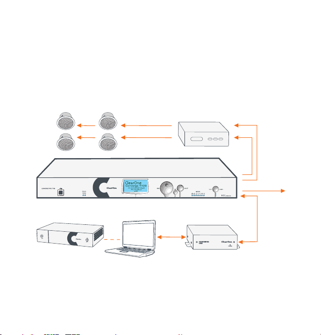
USB Interface Application
The CONVERGE USB allows audio sources/destinations to connect via
USB to CONVERGE Pro/SR mixers. The following diagram shows how
a CONVERGE Pro can be connected to a PC/laptop or COLLABORATE
Room via USB.
CONVERGE USB Used as USB Interface for CONVERGE Pro
Loud Speakers
COLLABORATE Room or
Laptop/PC running UC Application
2
CONVERGE Pro Unit
or
Amplifier
CONVERGE USB
USB
Audio
Transmit and Receive
Telephone Line
E-bus
From
LINK Out
E-bus To
LINK In
Page 5

QUICK-START GUIDE
• Up to four CONVERGE USB units with unique channel pairs can
be attached to a single CONVERGE Pro/SR site. Refer to “Link
Channel Selection” later in this document for instructions on how to
select the Tx/Rx channels.
• There is no limit to the number of units if they all share the same
bus.
• Audio control is performed in the UC Application or COLLABORATE
Room application. See “Configure and Set Audio Controls” for more
detail.
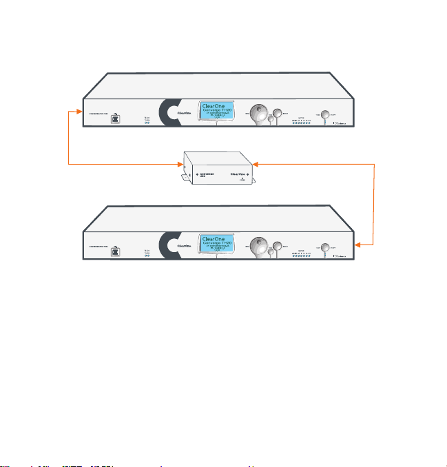
E-bus Extender Application
The CONVERGE USB application as an E-bus extender can, for example,
be up to 200 feet from the stack, then re-send the E-bus signals for up to
another 200 feet to the next E-bus component.
The following diagram illustrates the use of the CONVERGE USB as an
E-bus extender.
3
Page 6
CONVERGE USB INTERFACE
CONVERGE USB
CONVERGE Pro Unit
CONVERGE Pro Unit
E-bus
From
LINK Out
E-bus To
LINK In
E-bus
From
LINK Out
E-bus To
LINK In
(Up to 200 Ft. Max. Length) (Up to 200 Ft. Max. Length)
CONVERGE USB Used as E-bus Extender for CONVERGE Pro
Note: Link Channel Selection is NOT required when the
CONVERGE USB is used only as an E-bus extender with no USB
Tx/Rx channels used.
4
Page 7
QUICK-START GUIDE
Procedure Summary
These steps, detailed in the subsequent sections, must be done in the
following order to use the CONVERGE USB in your CONVERGE Pro Site:
1. Verify the CONVERGE Pro firmware is at version 4.X or higher.
Update if needed using CONVERGE Console.
2. Select the Expansion bus (E-bus) Link Channels by connecting a
terminal block to the CONVERGE USB Control/Status connector at
the back of the device.
Note: Not required if the CONVERGE USB is to be used only as
a E-bus extender with no USB In/Out channels. Steps for “Link
Channel Selection” are described later in this document.
3. Connect the CONVERGE USB to the updated CONVERGE Pro/SR
via the E-bus.
4. Route the CONVERGE USB Transmit and Receive audio channels
with CONVERGE Console.
Note: Not required if the CONVERGE USB is to be used only as a
E-bus extender with no USB Tx/Rx channels.
5. Configure and set audio controls on the PC/Laptop or
COLLABORATE Room codec.
5
Page 8
CONVERGE USB INTERFACE
VERIFY THE CONVERGE PRO FIRMWARE
Verify your CONVERGE Console is operating at version 4.X or higher.
The CONVERGE USB audio interfaces are not recognized by systems
running older versions and the 4.X versions offer significant upgrades
from previous versions. ClearOne strongly encourages users to upgrade
all firmware to the latest release version.
Instructions for updating from version 1.X, 2.X and 3X are detailed later in
this document.
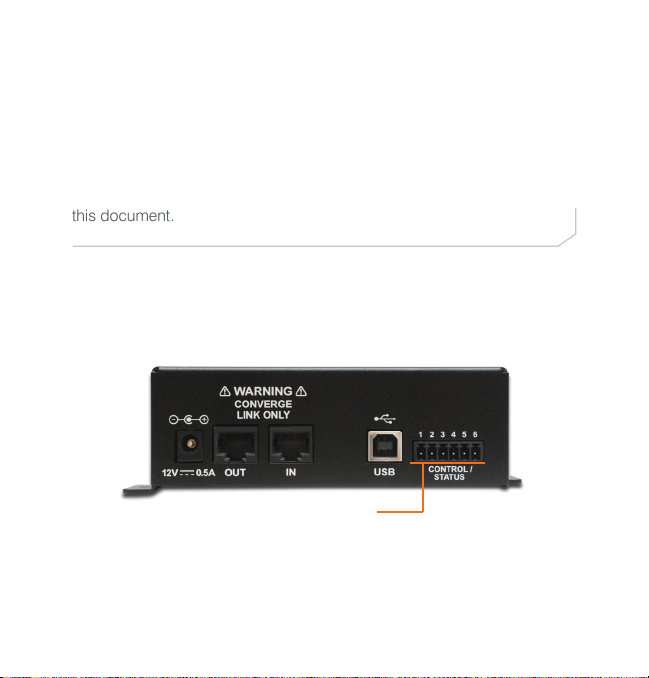
LINK CHANNEL SELECTION
Set each CONVERGE USB unit for both Transmit and Receive channels
using jumpers across a terminal block that is inserted into the 6-pin
Control/Status connector at the back of the CONVERGE USB unit.
Control/Status Connector
for terminal block with jumpers
6
Page 9

QUICK-START GUIDE
The terminal block pins are numbered from left to right 1, 2, 3, 4, 5 and 6.
The pins 1 and 3 are the inputs used to select different pairs of channels.
Channel selections are made by connecting combinations of pins 1 and
3 to pin 6. Pins 2, 4 and 5 must not be used to avoid equipment damage.
All E-bus signals will pass through the CONVERGE USB, but only the
selected Tx/Rx channels will be used by the CONVERGE USB.
The following illustration show the possible pin/channel selections using
jumper wires on the terminal block:
No
Connector
Tx channel - K
Rx channel - L
Tx channel - O
Rx channel - P
Tx channel - M
Rx channel - N
Tx channel - Q
Rx channel - R
7
Page 10
CONVERGE USB INTERFACE
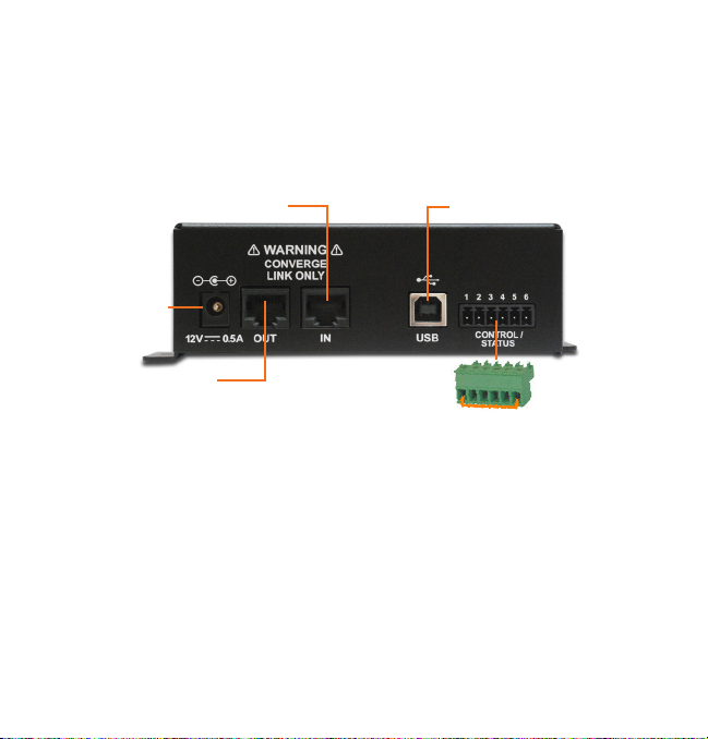
CONNECTING THE CONVERGE USB UNIT
Connect the CONVERGE USB units to the CONVERGE Pro/SR stack via
the E-bus connections using CAT5/CAT6-24AWG solid conductor RJ45
cables. Power to the CONVERGE USB is supplied by the standard 12V
DC power adapter supplied with the unit.
E-bus LINK IN from Stack
12V DC
Power
Input
E-bus LINK OUT
(Not required if unit is at end of stack)
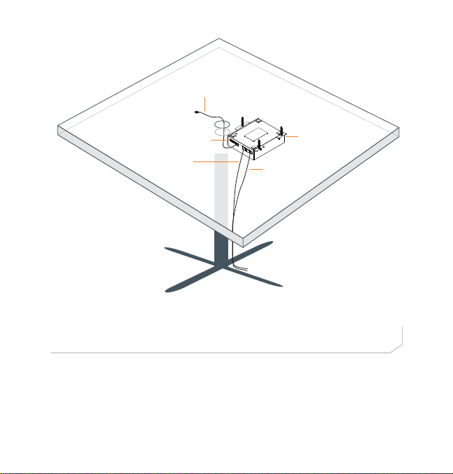
Mounting
The CONVERGE USB Interface can be conveniently mounted under
the table of a conference room. Place screws through the tabs on the
sides of the unit into the underside of the table. (Screws not provided.)
Pass the USB cable though to the top for use with customer computer
equipment, and route the Link In, Link Out (if needed) and power cables
to their connections.
USB Connection to
PC/Laptop
Terminal Block for
Channel Selection
8
Page 11
QUICK-START GUIDE
Computer USB
Connector
CONVERGE USB
Power
Cable
Mounted Under
Table
Control/Status Port
Terminal Block
Link In
(Optional Link Out
cable not shown)
Sample Table
The CONVERGE USB Interface can also be placed near the CONVERGE
Pro units or at any other location if care is taken to remain within the
operational limits of the USB, power and E-bus cabling.
9
Page 12
CONVERGE USB INTERFACE
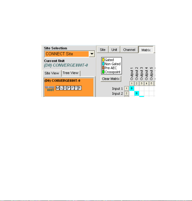
ROUTING THE CONVERGE USB CHANNELS
Complete the audio channel routing in the Matrix in CONVERGE Console.
In CONVERGE Console, select any device in the site, then click on the
Matrix tab.
As selected by the terminal block, route the signals that will be in Inputs
and Outputs for the USB device connected through the CONVERGE
USB.
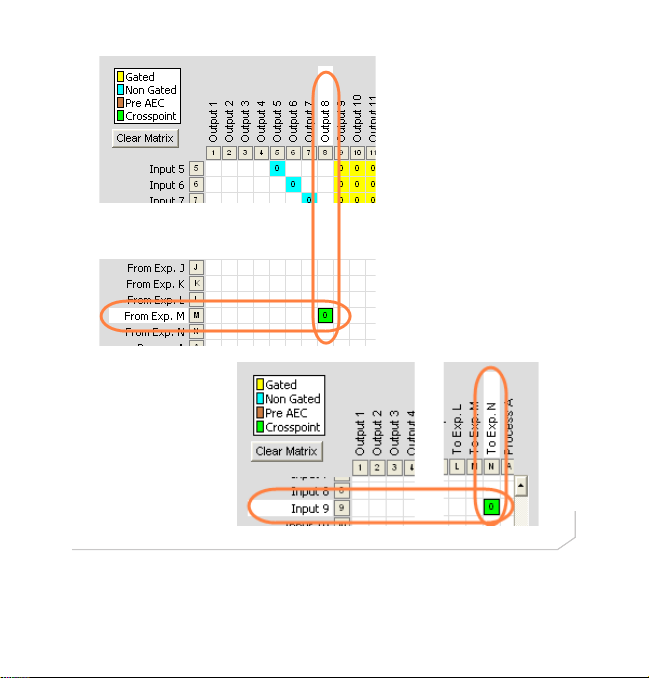
For example: if a terminal block jumper is between pins 1 and 6, then the
CONVERGE Pro channels are M for transmit and N for receive. These
can then be routed to the desired inputs and outputs.
The following two screen captures show audio from the CONVERGE
USB on Channel M going to Output 8, and Channel N receiving audio
from Input 9 then sending it to the CONVERGE USB.
10
Page 13
QUICK-START GUIDE
11
Page 14
CONVERGE USB INTERFACE
CONFIGURE AND SET AUDIO CONTROLS
Audio control for the audio interfaced to the CONVERGE Pro system
is applied in the laptop or PC running the UC application or by
COLLABORATE Room.
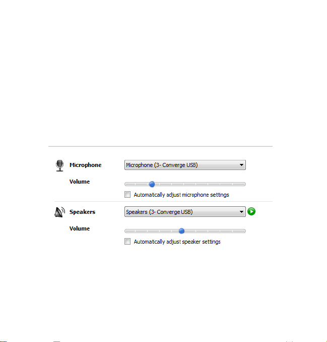
Microphone, Speakers and Volume in the UC Application
In the UC client, set the CONVERGE USB as the microphone and speaker audio devices. Different client applications vary in the way the present
these controls. Two examples shown below are for Skype™ and Lync®.
Skype Example
12
Page 15
QUICK-START GUIDE
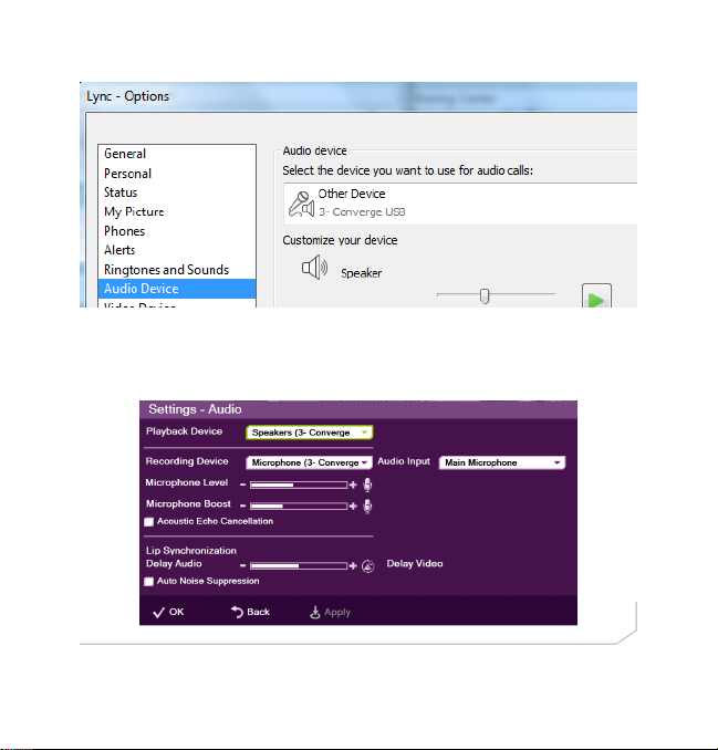
Lync Example
Microphone, Speakers and Volume in COLLABORATE Room
In the COLLABORATE Room settings, assign the CONVERGE USB as
the recording and playback audio devices.
13
Page 16

CONVERGE USB INTERFACE
UPGRADING FROM OLDER VERSIONS OF CONVERGE FIRMWARE
Please follow the steps listed below to upgrade your firmware:
NOTE: Save the CONVERGE Console site file before performing any firmware
upgrade.
Upgrading from CONVERGE Pro 3.X firmware
1. Remove any 1.X, 2.X and 4.X units from the stack by disconnecting the
expansion bus link cable from the 3.X units.
2. Re-connect to the 3.X stack with CONVERGE Console.
3. Download the 4.X firmware file to the stack of units.
4. The units will default and reboot after the download of 4.X firmware.
5. Units are fully upgraded.
6. Verify units have been upgraded by checking the firmware version on the
front panel.
Reconnect all E-bus cables, if needed, to complete the stack of units.
Upgrading from CONVERGE Pro 2.X firmware
1. Remove any 1.X, 3.X and 4.X units from the stack by disconnecting the
expansion bus link cable from the 2.X units.
2. Re-connect to the 2.X stack with CONVERGE Console.
3. Download the 4.X firmware file to the stack of units.
4. The units will default and reboot after the download of 4.X firmware. The 2.X
to 4.X upgrade requires the firmware to be loaded twice to complete the
version upgrade.
14
Page 17
QUICK-START GUIDE
5. Units are fully upgraded.
6. Verify units have been upgraded by checking the firmware version on the
front panel.
Reconnect all E-bus cables, if needed, to complete the stack of units.
Upgrading from CONVERGE Pro 1.X firmware
1. Remove any 2.X, 3.X and 4.X units from the stack by disconnecting the
expansion bus link cable from the 1.X units.
2. Re-connect to the 1.X stack with CONVERGE Console.
3. Download the 4.X firmware file to the stack of units.
4. The units will default and reboot after the download of 4.X firmware. The 1.X
to 4.X upgrade requires the firmware to be loaded twice to complete the
version upgrade.
5. Reconnect to the stack with CONVERGE Console. Download 4.X a second
time to the units. The units will reboot.
6. Units are fully upgraded.
7. Verify units have been upgraded by checking the firmware version on the
front panel.
Reconnect all E-bus cables, if needed, to complete the stack of units.
15
Page 18
CONVERGE USB INTERFACE
PART NUMBERS
910-151-806 CONVERGE USB
CLEARONE CONTACTS
HEADQUARTERS:
Salt Lake City, UT USA
5225 Wiley Post Way
Suite 500
Salt Lake City, UT 84116
Sales: 800-705-2103
Toll Free: 800.945.7730
Fax: 801.977.0087
e-mail: sales@clearone.com
EMEA:
Tel: +44 (0) 1189 036 053
e-mail: global@clearone.co
LATAM:
Tel: 801-974-3621
e-mail: global@clearone.com
TechSales
Tel: 800.705.2103
e-mail: techsales@clearone.com
Technical Support
Tel: 800.283.5936
e-mail: tech.support@clearone.co
APAC:
Tel: +852 3590 4526
e-mail: global@clearone.com
Middle East:
Tel: +852 3590 4526
e-mail: global@clearone.com
Information in this document is subject to change without notice. 800-151-806 Revision 1.0 July, 2013
© 2013 ClearOne, Inc. All rights reserved.
16
 Loading...