

Page 1
CONVERGE® PRO 880
CONVERGE® SR 1212
|
880T | 880TA | 840T | 8i | TH20 | VH20
|
SR 1212TA
|
Beamforming Microphone Array, CONVERGE USB
CONNECT™ CobraNet®, CONNECT AVB Network Bridges
Professional Conferencing Systems
INSTALLATION & OPERATION MANUAL
|
Page 2

TECHNICAL SUPPORT
Telephone 1.800.283.5936
1.801.974.3760
Fax 1.801.977.0087
Email tech.support@clearone.com
Web www.clearone.com
CONVERGE PRO 880/880T/880TA/840T/8i/TH20/VH20,
CONVERGE SR 1212/SR 1212TA
Beamforming Microphone Array
CONNECT CobraNet/AVB Network Bridge
CONVERGE USB Network Peripheral
INSTALLATION & OPERATION MANUAL
CLEARONE PART NO. 800-151-880 (REVISION 4.3) Oct. 2013
© 2013 ClearOne - All rights reserved. Information in this document is
subject to change without notice. Other product names may be registered
trademarks of their respective owners who do not necessarily endorse
ClearOne or ClearOne’s products in the United States and/or other countries.
Adobe® Flash® Copyright and Trademark Notice
Adobe® Flash® Player. Copyright © 1996 – 2013 Adobe Systems
Incorporated. All Rights Reserved. Adobe and Flash are either trademarks or
registered trademarks in the United States and/or other countries.
Page 3

TABLE OF CONTENTS
CHAPTER 1: INTRODUCTION 1
CONVERGE Pro Product Family Overview. . . . . . . . . . . . . . . . . . . . . . . . . . . . . . . . . . . . . . . . . . . . . . . . . . . . 1
Important Safety Information . . . . . . . . . . . . . . . . . . . . . . . . . . . . . . . . . . . . . . . . . . . . . . . . . . . . . . . . . . . . . . 5
CONVERGE Pro Product Descriptions . . . . . . . . . . . . . . . . . . . . . . . . . . . . . . . . . . . . . . . . . . . . . . . . . . . . . . 6
Customer Service and Support . . . . . . . . . . . . . . . . . . . . . . . . . . . . . . . . . . . . . . . . . . . . . . . . . . . . . . . . . . . 18
Warranty Information. . . . . . . . . . . . . . . . . . . . . . . . . . . . . . . . . . . . . . . . . . . . . . . . . . . . . . . . . . . . . . . . . . . . 18
Operating Requirements. . . . . . . . . . . . . . . . . . . . . . . . . . . . . . . . . . . . . . . . . . . . . . . . . . . . . . . . . . . . . . . . . 19
System Requirements. . . . . . . . . . . . . . . . . . . . . . . . . . . . . . . . . . . . . . . . . . . . . . . . . . . . . . . . . . . . . . . . . . . 19
Unpacking. . . . . . . . . . . . . . . . . . . . . . . . . . . . . . . . . . . . . . . . . . . . . . . . . . . . . . . . . . . . . . . . . . . . . . . . . . . . 20
Controls and Connections . . . . . . . . . . . . . . . . . . . . . . . . . . . . . . . . . . . . . . . . . . . . . . . . . . . . . . . . . . . . . . . 32
CHAPTER 2: EXPANSION BUS & LCD PROGRAMMING 43
Expansion Bus . . . . . . . . . . . . . . . . . . . . . . . . . . . . . . . . . . . . . . . . . . . . . . . . . . . . . . . . . . . . . . . . . . . . . . . . 43
Device IDs. . . . . . . . . . . . . . . . . . . . . . . . . . . . . . . . . . . . . . . . . . . . . . . . . . . . . . . . . . . . . . . . . . . . . . . . . . . . 44
LCD Programming Overview . . . . . . . . . . . . . . . . . . . . . . . . . . . . . . . . . . . . . . . . . . . . . . . . . . . . . . . . . . . . . 46
LCD Channels Menu. . . . . . . . . . . . . . . . . . . . . . . . . . . . . . . . . . . . . . . . . . . . . . . . . . . . . . . . . . . . . . . . . . . . 49
LCD Settings Menu. . . . . . . . . . . . . . . . . . . . . . . . . . . . . . . . . . . . . . . . . . . . . . . . . . . . . . . . . . . . . . . . . . . . . 50
LCD Macros Menu . . . . . . . . . . . . . . . . . . . . . . . . . . . . . . . . . . . . . . . . . . . . . . . . . . . . . . . . . . . . . . . . . . . . . 52
LCD Preset Menu . . . . . . . . . . . . . . . . . . . . . . . . . . . . . . . . . . . . . . . . . . . . . . . . . . . . . . . . . . . . . . . . . . . . . . 53
CHAPTER 3: CONVERGE CONSOLE PROGRAMMING 54
Installing CONVERGE Console . . . . . . . . . . . . . . . . . . . . . . . . . . . . . . . . . . . . . . . . . . . . . . . . . . . . . . . . . . . 54
CONVERGE Console Overview . . . . . . . . . . . . . . . . . . . . . . . . . . . . . . . . . . . . . . . . . . . . . . . . . . . . . . . . . . . 57
Site File Overview . . . . . . . . . . . . . . . . . . . . . . . . . . . . . . . . . . . . . . . . . . . . . . . . . . . . . . . . . . . . . . . . . . . . . . 62
Connect to a Site . . . . . . . . . . . . . . . . . . . . . . . . . . . . . . . . . . . . . . . . . . . . . . . . . . . . . . . . . . . . . . . . . . . . . . 65
Site Properties. . . . . . . . . . . . . . . . . . . . . . . . . . . . . . . . . . . . . . . . . . . . . . . . . . . . . . . . . . . . . . . . . . . . . . . . . 66
Unit Properties . . . . . . . . . . . . . . . . . . . . . . . . . . . . . . . . . . . . . . . . . . . . . . . . . . . . . . . . . . . . . . . . . . . . . . . . 71
CONVERGE Pro VH20 Unit Properties . . . . . . . . . . . . . . . . . . . . . . . . . . . . . . . . . . . . . . . . . . . . . . . . . . . . . . 76
Beamforming Microphone Array Unit Properties . . . . . . . . . . . . . . . . . . . . . . . . . . . . . . . . . . . . . . . . . . . . . . 80
CONNECT AVB Unit Properties . . . . . . . . . . . . . . . . . . . . . . . . . . . . . . . . . . . . . . . . . . . . . . . . . . . . . . . . . . . 82
CONNECT CobraNet Unit Properties. . . . . . . . . . . . . . . . . . . . . . . . . . . . . . . . . . . . . . . . . . . . . . . . . . . . . . . 83
Configuration Mode Overview . . . . . . . . . . . . . . . . . . . . . . . . . . . . . . . . . . . . . . . . . . . . . . . . . . . . . . . . . . . . 84
Site Tab . . . . . . . . . . . . . . . . . . . . . . . . . . . . . . . . . . . . . . . . . . . . . . . . . . . . . . . . . . . . . . . . . . . . . . . . . . . . . . 85
Unit Tab. . . . . . . . . . . . . . . . . . . . . . . . . . . . . . . . . . . . . . . . . . . . . . . . . . . . . . . . . . . . . . . . . . . . . . . . . . . . . . 85
Channel Tab Overview . . . . . . . . . . . . . . . . . . . . . . . . . . . . . . . . . . . . . . . . . . . . . . . . . . . . . . . . . . . . . . . . . 101
AEC (Acoustic Echo Cancellation) . . . . . . . . . . . . . . . . . . . . . . . . . . . . . . . . . . . . . . . . . . . . . . . . . . . . . . . . 106
NC (Noise Cancellation) . . . . . . . . . . . . . . . . . . . . . . . . . . . . . . . . . . . . . . . . . . . . . . . . . . . . . . . . . . . . . . . . 109
Filters. . . . . . . . . . . . . . . . . . . . . . . . . . . . . . . . . . . . . . . . . . . . . . . . . . . . . . . . . . . . . . . . . . . . . . . . . . . . . . . 111
AGC/ALC (Automatic Gain Control/Automatic Level Control) Tab. . . . . . . . . . . . . . . . . . . . . . . . . . . . . . . . 116
Mic Gating. . . . . . . . . . . . . . . . . . . . . . . . . . . . . . . . . . . . . . . . . . . . . . . . . . . . . . . . . . . . . . . . . . . . . . . . . . . 118
Mic Input Settings . . . . . . . . . . . . . . . . . . . . . . . . . . . . . . . . . . . . . . . . . . . . . . . . . . . . . . . . . . . . . . . . . . . . . 122
Line Input Settings . . . . . . . . . . . . . . . . . . . . . . . . . . . . . . . . . . . . . . . . . . . . . . . . . . . . . . . . . . . . . . . . . . . . 128
Telco/VoIP Rx Settings . . . . . . . . . . . . . . . . . . . . . . . . . . . . . . . . . . . . . . . . . . . . . . . . . . . . . . . . . . . . . . . . . 133
Output Settings. . . . . . . . . . . . . . . . . . . . . . . . . . . . . . . . . . . . . . . . . . . . . . . . . . . . . . . . . . . . . . . . . . . . . . . 143
Telco/VoIP Tx Settings. . . . . . . . . . . . . . . . . . . . . . . . . . . . . . . . . . . . . . . . . . . . . . . . . . . . . . . . . . . . . . . . . . 147
Processing Settings . . . . . . . . . . . . . . . . . . . . . . . . . . . . . . . . . . . . . . . . . . . . . . . . . . . . . . . . . . . . . . . . . . . 154
Fader Settings. . . . . . . . . . . . . . . . . . . . . . . . . . . . . . . . . . . . . . . . . . . . . . . . . . . . . . . . . . . . . . . . . . . . . . . . 162
Matrix Tab . . . . . . . . . . . . . . . . . . . . . . . . . . . . . . . . . . . . . . . . . . . . . . . . . . . . . . . . . . . . . . . . . . . . . . . . . . . 167
Page 4

TABLE OF CONTENTS (continued)
AEC Reference/PA Adapt Reference Tab . . . . . . . . . . . . . . . . . . . . . . . . . . . . . . . . . . . . . . . . . . . . . . . . . . . 171
Macro Tab . . . . . . . . . . . . . . . . . . . . . . . . . . . . . . . . . . . . . . . . . . . . . . . . . . . . . . . . . . . . . . . . . . . . . . . . . . . 174
Gating Tab. . . . . . . . . . . . . . . . . . . . . . . . . . . . . . . . . . . . . . . . . . . . . . . . . . . . . . . . . . . . . . . . . . . . . . . . . . . 178
Control Tab . . . . . . . . . . . . . . . . . . . . . . . . . . . . . . . . . . . . . . . . . . . . . . . . . . . . . . . . . . . . . . . . . . . . . . . . . . 181
String Tab . . . . . . . . . . . . . . . . . . . . . . . . . . . . . . . . . . . . . . . . . . . . . . . . . . . . . . . . . . . . . . . . . . . . . . . . . . . 184
Event Scheduler Tab. . . . . . . . . . . . . . . . . . . . . . . . . . . . . . . . . . . . . . . . . . . . . . . . . . . . . . . . . . . . . . . . . . . 186
Database Tab . . . . . . . . . . . . . . . . . . . . . . . . . . . . . . . . . . . . . . . . . . . . . . . . . . . . . . . . . . . . . . . . . . . . . . . . 188
Optimizing Gain Structure. . . . . . . . . . . . . . . . . . . . . . . . . . . . . . . . . . . . . . . . . . . . . . . . . . . . . . . . . . . . . . . 193
Drag and Drop Configuration . . . . . . . . . . . . . . . . . . . . . . . . . . . . . . . . . . . . . . . . . . . . . . . . . . . . . . . . . . . . 196
Preset Mode . . . . . . . . . . . . . . . . . . . . . . . . . . . . . . . . . . . . . . . . . . . . . . . . . . . . . . . . . . . . . . . . . . . . . . . . . 202
File Menu Overview. . . . . . . . . . . . . . . . . . . . . . . . . . . . . . . . . . . . . . . . . . . . . . . . . . . . . . . . . . . . . . . . . . . . 209
Print Reports . . . . . . . . . . . . . . . . . . . . . . . . . . . . . . . . . . . . . . . . . . . . . . . . . . . . . . . . . . . . . . . . . . . . . . . . . 211
View Menu Overview. . . . . . . . . . . . . . . . . . . . . . . . . . . . . . . . . . . . . . . . . . . . . . . . . . . . . . . . . . . . . . . . . . . 212
Add Menu . . . . . . . . . . . . . . . . . . . . . . . . . . . . . . . . . . . . . . . . . . . . . . . . . . . . . . . . . . . . . . . . . . . . . . . . . . . 214
Connect Menu Overview. . . . . . . . . . . . . . . . . . . . . . . . . . . . . . . . . . . . . . . . . . . . . . . . . . . . . . . . . . . . . . . . 217
Modes Menu Overview . . . . . . . . . . . . . . . . . . . . . . . . . . . . . . . . . . . . . . . . . . . . . . . . . . . . . . . . . . . . . . . . . 218
Services Menu Overview. . . . . . . . . . . . . . . . . . . . . . . . . . . . . . . . . . . . . . . . . . . . . . . . . . . . . . . . . . . . . . . . 219
Dialer. . . . . . . . . . . . . . . . . . . . . . . . . . . . . . . . . . . . . . . . . . . . . . . . . . . . . . . . . . . . . . . . . . . . . . . . . . . . . . . 220
Phonebook . . . . . . . . . . . . . . . . . . . . . . . . . . . . . . . . . . . . . . . . . . . . . . . . . . . . . . . . . . . . . . . . . . . . . . . . . . 222
Label Editor. . . . . . . . . . . . . . . . . . . . . . . . . . . . . . . . . . . . . . . . . . . . . . . . . . . . . . . . . . . . . . . . . . . . . . . . . . 224
Device Log . . . . . . . . . . . . . . . . . . . . . . . . . . . . . . . . . . . . . . . . . . . . . . . . . . . . . . . . . . . . . . . . . . . . . . . . . . 225
Event Log . . . . . . . . . . . . . . . . . . . . . . . . . . . . . . . . . . . . . . . . . . . . . . . . . . . . . . . . . . . . . . . . . . . . . . . . . . . 228
Web Builder. . . . . . . . . . . . . . . . . . . . . . . . . . . . . . . . . . . . . . . . . . . . . . . . . . . . . . . . . . . . . . . . . . . . . . . . . . 230
Firmware Loader. . . . . . . . . . . . . . . . . . . . . . . . . . . . . . . . . . . . . . . . . . . . . . . . . . . . . . . . . . . . . . . . . . . . . . 235
Debug Console. . . . . . . . . . . . . . . . . . . . . . . . . . . . . . . . . . . . . . . . . . . . . . . . . . . . . . . . . . . . . . . . . . . . . . . 239
Execute Presets . . . . . . . . . . . . . . . . . . . . . . . . . . . . . . . . . . . . . . . . . . . . . . . . . . . . . . . . . . . . . . . . . . . . . . 245
APPENDIX A: APPLICATION PROGRAMMER’S INTERFACE 247
Type and Device IDs. . . . . . . . . . . . . . . . . . . . . . . . . . . . . . . . . . . . . . . . . . . . . . . . . . . . . . . . . . . . . . . . . . . 247
Conventions . . . . . . . . . . . . . . . . . . . . . . . . . . . . . . . . . . . . . . . . . . . . . . . . . . . . . . . . . . . . . . . . . . . . . . . . . 247
Command Form Description . . . . . . . . . . . . . . . . . . . . . . . . . . . . . . . . . . . . . . . . . . . . . . . . . . . . . . . . . . . . 247
Groups and Channels. . . . . . . . . . . . . . . . . . . . . . . . . . . . . . . . . . . . . . . . . . . . . . . . . . . . . . . . . . . . . . . . . . 248
Meter Type Definitions Table . . . . . . . . . . . . . . . . . . . . . . . . . . . . . . . . . . . . . . . . . . . . . . . . . . . . . . . . . . . . . 249
Serial Commands . . . . . . . . . . . . . . . . . . . . . . . . . . . . . . . . . . . . . . . . . . . . . . . . . . . . . . . . . . . . . . . . . . . . . 257
Serial Command Support Table . . . . . . . . . . . . . . . . . . . . . . . . . . . . . . . . . . . . . . . . . . . . . . . . . . . . . . . . . . 322
All Models: RS-232 Port . . . . . . . . . . . . . . . . . . . . . . . . . . . . . . . . . . . . . . . . . . . . . . . . . . . . . . . . . . . . . . . . 329
Connecting with Telnet . . . . . . . . . . . . . . . . . . . . . . . . . . . . . . . . . . . . . . . . . . . . . . . . . . . . . . . . . . . . . . . . . 329
Page 5

TABLE OF CONTENTS (continued)
All Models: RS-232 Port . . . . . . . . . . . . . . . . . . . . . . . . . . . . . . . . . . . . . . . . . . . . . . . . . . . . . . . . . . . . . . . . 329
APPENDIX B: DEFAULT PINOUTS 331
Control/Status Ports . . . . . . . . . . . . . . . . . . . . . . . . . . . . . . . . . . . . . . . . . . . . . . . . . . . . . . . . . . . . . . . . . . . 331
All Models: RS-232 Port . . . . . . . . . . . . . . . . . . . . . . . . . . . . . . . . . . . . . . . . . . . . . . . . . . . . . . . . . . . . . . . . 338
APPENDIX C: FIRMWARE LOADING PROCEDURE 339
APPENDIX D: SPECIFICATIONS 341
Converge Pro 880. . . . . . . . . . . . . . . . . . . . . . . . . . . . . . . . . . . . . . . . . . . . . . . . . . . . . . . . . . . . . . . . . . . . . 341
Converge Pro 880T. . . . . . . . . . . . . . . . . . . . . . . . . . . . . . . . . . . . . . . . . . . . . . . . . . . . . . . . . . . . . . . . . . . . 343
Converge Pro 880TA. . . . . . . . . . . . . . . . . . . . . . . . . . . . . . . . . . . . . . . . . . . . . . . . . . . . . . . . . . . . . . . . . . . 345
Converge Pro 840T . . . . . . . . . . . . . . . . . . . . . . . . . . . . . . . . . . . . . . . . . . . . . . . . . . . . . . . . . . . . . . . . . . . 347
Converge Pro 8i . . . . . . . . . . . . . . . . . . . . . . . . . . . . . . . . . . . . . . . . . . . . . . . . . . . . . . . . . . . . . . . . . . . . . . 349
CONVERGE PRO 8i (continued) . . . . . . . . . . . . . . . . . . . . . . . . . . . . . . . . . . . . . . . . . . . . . . . . . . . . . . . . . 350
Converge Pro TH20 . . . . . . . . . . . . . . . . . . . . . . . . . . . . . . . . . . . . . . . . . . . . . . . . . . . . . . . . . . . . . . . . . . . 351
Converge Pro VH20 . . . . . . . . . . . . . . . . . . . . . . . . . . . . . . . . . . . . . . . . . . . . . . . . . . . . . . . . . . . . . . . . . . . 352
Converge SR 1212 . . . . . . . . . . . . . . . . . . . . . . . . . . . . . . . . . . . . . . . . . . . . . . . . . . . . . . . . . . . . . . . . . . . . 353
Converge SR 1212A . . . . . . . . . . . . . . . . . . . . . . . . . . . . . . . . . . . . . . . . . . . . . . . . . . . . . . . . . . . . . . . . . . . 355
Beamforming Microphone Array. . . . . . . . . . . . . . . . . . . . . . . . . . . . . . . . . . . . . . . . . . . . . . . . . . . . . . . . . . 356
CONNECT CobraNet/AVB Network Bridges . . . . . . . . . . . . . . . . . . . . . . . . . . . . . . . . . . . . . . . . . . . . . . . . 357
CONVERGE USB Interface. . . . . . . . . . . . . . . . . . . . . . . . . . . . . . . . . . . . . . . . . . . . . . . . . . . . . . . . . . . . . . 357
APPENDIX E: COMPLIANCE 358
FCC Part 15/ICES-003 Compliance . . . . . . . . . . . . . . . . . . . . . . . . . . . . . . . . . . . . . . . . . . . . . . . . . . . . . . . 358
FCC Part 68 Compliance . . . . . . . . . . . . . . . . . . . . . . . . . . . . . . . . . . . . . . . . . . . . . . . . . . . . . . . . . . . . . . . 358
Electrical Safety Advisory . . . . . . . . . . . . . . . . . . . . . . . . . . . . . . . . . . . . . . . . . . . . . . . . . . . . . . . . . . . . . . . 359
IC COMPLIANCE . . . . . . . . . . . . . . . . . . . . . . . . . . . . . . . . . . . . . . . . . . . . . . . . . . . . . . . . . . . . . . . . . . . . . 359
EUROPEAN COMPLIANCE . . . . . . . . . . . . . . . . . . . . . . . . . . . . . . . . . . . . . . . . . . . . . . . . . . . . . . . . . . . . . 360
EUROPEAN COMPLIANCE . . . . . . . . . . . . . . . . . . . . . . . . . . . . . . . . . . . . . . . . . . . . . . . . . . . . . . . . . . . . . 362
NEW ZEALAND COMPLIANCE . . . . . . . . . . . . . . . . . . . . . . . . . . . . . . . . . . . . . . . . . . . . . . . . . . . . . . . . . . 364
JAPANESE COMPLIANCE . . . . . . . . . . . . . . . . . . . . . . . . . . . . . . . . . . . . . . . . . . . . . . . . . . . . . . . . . . . . . . 364
APPENDIX F: PROVISIONING THE CONVERGE VH20 365
Provisioning The Converge VH20. . . . . . . . . . . . . . . . . . . . . . . . . . . . . . . . . . . . . . . . . . . . . . . . . . . . . . . . . 365
GLOSSARY 370
Page 6

CHAPTER 1: INTRODUCTION
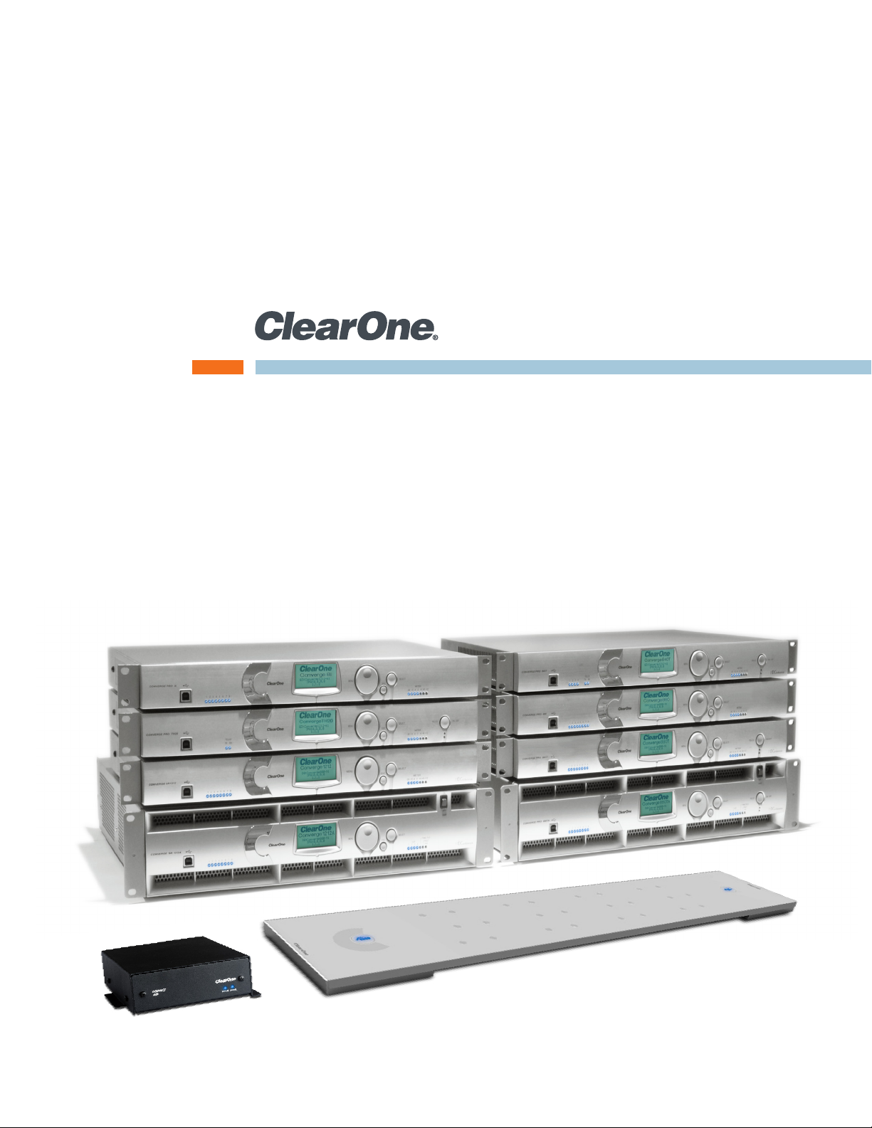
CONVERGE PRO PRODUCT FAMILY OVERVIEW
Congratulations! You have purchased a ClearOne® CONVERGE® Pro audio conferencing solution. The
CONVERGE Pro product family represents a revolutionary advance in state-of-the-art audio technology for largescale conferencing applications.
ClearOne introduced its first audio conferencing products to the market in 1990 under the brand name Gentner®.
Today, ClearOne has over 80,000 installations worldwide in organizations ranging from the Fortune 1,000 to the
federal government. ClearOne products are used in the most demanding conferencing applications, where they
consistently deliver industry-leading audio quality and unsurpassed reliability.
ClearOne’s proprietary Distributed Echo Cancellation® (DEC) technology forms the foundation of the CONVERGE
Pro product family, and provides optimal audio quality for today’s distributed conferencing environments. In
addition to DEC, other ClearOne innovations – including noise cancellation, automatic gain and level control,
advanced microphone gating, adaptive ambient, and ClearEffect™ wideband audio emulation – produce crystalclear audio that is equivalent to conference participants being in the same room.
Applications
The CONVERGE Pro product family provides scalable conferencing solutions for any size venue. Some common
applications include:
• Boardrooms
• Training rooms
• Courtrooms
• Multimedia rooms
• Distance learning
• Auditoriums
• Houses of worship
• Sound reinforcement
• Large meeting venues
1
Page 7

Models
The CONVERGE Pro product family and associated products includes the following:
• CONVERGE Pro 880
• CONVERGE Pro 880T
• CONVERGE Pro 880TA
• CONVERGE Pro 840T
• CONVERGE Pro TH20
• CONVERGE Pro VH20
• CONVERGE Pro 8i
• CONVERGE Pro SR1212
• CONVERGE Pro SR1212A
• Beamforming Microphone Array
• CONNECT CobraNet and CONNECT AVB Network Bridges
• CONVERGE USB Interface
Common Benefits
Each product in the CONVERGE Pro product family offers the following benefits:
• Superior audio quality
• ClearOne’s next generation signal processing algorithms
• Field-proven conferencing technology
• Flexible configuration and expandability
• Improved configuration and management software
• Simplified programming
• Reduced installation times
• Best-in-class processing speed
• ClearOne’s world-class customer service, technical support, and field engineering services
Common Features
The leading-edge features common to all products in the CONVERGE Pro family include:
• USB connector on front panel for easy connectivity with a laptop or PC
• Dual RJ-45 Ethernet ports
• Dual RJ-45 expansion bus ports
• TDM (Time Division Multiplexed) mix/minus audio and control buses
• RS-232 serial port (up to 115,200 bps)
• Dual DB-25 control/status GPIO (General Purpose Input/Output) Ports
• Mini-phoenix audio input/output connectors (color-coded by channel type)
• Differential inputs and outputs
Feature Enhancements
CONVERGE Pro feature enhancements include:
• ClearOne’s next-generation Distributed Echo Cancellation—up to eight discrete digital signal processors
(DSPs) improve full-duplex performance and remove echo in the most difficult acoustic environments.
• New PTT (Push-to-Talk) microphone compatibility provides greater design and configuration flexibility.
• Advanced noise cancellation reduces background noise caused by fans, HVAC systems, and other
relatively constant background noise sources.
2
Page 8

• Up to eight independent signal processing blocks, each with 15 user-configurable filters (including all-pass,
low-pass, high-pass, low-shelving, high-shelving, and parametric), delay, and compression. ClearOne’s
unparalleled processing power enables you to use all of these features simultaneously in any combination,
allowing you to create optimized audio configurations for every environment and application.
• Enhanced expansion bus (E-bus) capabilities—connect up to 34 CONVERGE Pro units together and use
up to 96 microphones and 16 telephone lines in a single CONVERGE Pro installation.
• Increased distance between units—up to 200 feet/60.96 meters.
• Graphical, user-configurable routing matrix allows you to route any input channel to any output, processing,
or fader channel (or combination thereof) on any CONVERGE Pro unit, or across the expansion bus.
• Front panel control of mute and gain for all input and output channels.
• Safety mute button on the Console™ software button bar instantly mutes all outputs.
• ClearOne’s DSP (Digital Signal Processing) technology ensures crystal-clear audio between conferencing
sites.
AEC (Acoustical Echo Cancellation) Enhancements
• Smoothing filters to reduce artifacts
• Pre-AEC bypass channels
• Improved AEC adaption and noise suppression algorithms
• Automated Push-to-Talk microphone mode with AEC freezing
• Gain and gating control tracking
• Cross point gain adjustments
• Four fader channels
• Microphone preamp gain control
• 7 dB coarse gain and .5 dB fine gain increments for improved microphone gain matching
• AGC (Automatic Gain Control) algorithm
• ALC (Automatic Level Control) algorithm
Telephone Hybrid Enhancements (880T, 880TA, 840T, TH20)
• Custom telephone line settings for international teleconferencing and in-country localization
• Type I & Type II auto-sensing telephone interface (U.S. and E.U.)
• International impedance matching
• Improved TEC (Telco Echo Cancellation) with 31 millisecond tail time
• Continual TEC adaptation to telephone line conditions
• ClearEffect™ wideband audio emulation algorithm
• Digital anti-alias filter minimizes CO switching noise and hum
• ALC (Automatic Level Control) on telco receive channel
• Improved call management and processing
• Adjustable dial tone, DTMF attenuation
• Off-hook DTMF generation
• Robust dial tone detection
• Caller ID & selectable ringers
• Touch-tone dialing capability (44 character dial string)
• Analog telephone line compatibility
• 10 W speaker amplifier (880T, 880TA, 840T)
• Custom ring cadence detect
3
Page 9

VoIP and SIP Functionality (VH20)
• Voice over Internet Protocol functionality - Providing telephone functionality over an Internet connection
• SIP - Session Initiation Protocol used to establish, modify and terminate VoIP calls
• Support for wideband Audio – G.722
• ClearEffect™ wideband audio emulation algorithm
• ALC (Automatic Level Control) on telco receive channel
• Caller ID & selectable ringers
Beamforming Microphone Array Enhancements
• Beamforming & adaptive steering technology
• Next-generation Acoustic Echo Cancellation
• 24 microphone elements
• Mono and stereo modes for diverse applications
• Flexible mounting for ceiling
• Works with CONVERGE Pro products: 880, 840T, 880T, 880TA
• Expandable for larger room applications by daisy-chaining up to three arrays per CONVERGE Pro unit
• Adaptive acoustic processing automatically adjusts to room configuration for best possible audio pickup
• Replaces up to 10 traditional microphones, with twice the pick-up range
CONNECT CobraNet and CONNECT AVB Enhancements
• 8 x 8 I/O audio extends system boundaries, transmitting audio channels through network
• Works with all CONVERGE Pro and CONVERGE SR products
• Acts as an end-point device for the network, with up to 8 units on each E-bus
• Configuration through familiar CONVERGE Console software
• Firmware upgradable through CONVERGE Pro E-bus
• Modular approach to projects, with the ability to add and change CONNECT bridges as needed
• Installers can provide a solution based on network infrastructure, choosing CobraNet or AVB bridges
• Using the latest firmware and software, the CONNECT bridges keep the network updated without any
changes in main mixer hardware
• Configuration done through CONVERGE Pro unit with familiar and easy-to-use CONVERGE Console
software
CONVERGE USB Enhancements
• Provides USB audio In/Out between desktops/laptops and CONVERGE units
• Plug-and-play peripheral connects desktops/laptops with professional audio for ClearOne COLLABORATE
Desktop and other popular Unified Communications applications such as Skype™, Microsoft® Lync, and
Google Talk™
• Easily connects with ClearOne COLLABORATE Room video conferencing system for best-in-class audio
• Used as an Expansion bus extender by extending the distance to another 200 feet per unit using E-bus In &
Out ports
• Connects to CONVERGE units through E-bus
• Works with all existing CONVERGE Pro and SR products
• Powered through external power supply
• Terminal block jumpers control the E-bus channel selection
• Volume controlled through desktop/laptop
4
Page 10

IMPORTANT SAFETY INFORMATION
AVIS: RISQUE DE CHOC
ELECTRIQUE - NE PAS OUVRIR
Read all safety information before using this product.
1. Read these instructions.
2. Keep these instructions.
3. Heed all warnings.
4. Follow all instructions.
5. Do not use this apparatus near water.
6. Clean only with dry cloth.
7. Do not block any ventilation openings. Install in accordance with the manufacturer’s instructions.
8. Do not install near any heat sources such as radiators, heat registers, stoves, or other apparatus (including
amplifiers) that produce heat.
9. Do not defeat the safety purpose of the polarized or grounding-type plug. A polarized plug has two blades with
one wider than the other. A grounding type plug has two blades and a third grounding prong. The wide blade or
the third prong are provided for your safety. If the provided plug does not fit into your outlet, consult an electrician
for replacement of the obsolete outlet. The device must be connected to a earth grounded socket. For Norway:
Apparatet må tilkoples jordet stikkontakt. For Sweden: Apparaten skall anslutas till jordat uttag. For Finland: Laite
on liitettävä suojakoskettimilla varustettuun pistorasiaan.
10. Protect the power cord from being walked on or pinched particularly at plugs, convenience receptacles, and the
point where they exit from the apparatus.
11. Only use attachments/accessories specified by the manufacturer.
12. Use only with the cart, stand, tripod, bracket, or table specified by the manufacturer, or sold with the apparatus.
When a cart is used, use caution when moving the cart/apparatus combination to avoid injury from tip-over.
13. Unplug this apparatus during lightning storms or when unused for long periods of time.
14. Refer all servicing to qualified service personnel. Servicing is required when the apparatus has been damaged in
any way, such as power-supply cord or plug is damaged, liquid has been spilled or objects have fallen into the
apparatus, the apparatus has been exposed to rain or moisture, does not operate normally, or has been dropped.
15. Use the mains plug to disconnect the apparatus from the AC mains. The mains plug shall remain readily operable.
16. On/Off switch located on the front panel of the CONVERGE Pro 880TA and SR 1212A does NOT disconnect power
from the AC mains.
17. To completely disconnect unit power from the AC mains, disconnect the unit’s power cord from the mains socket.
To reconnect power, plug the unit’s power cord into the mains socket following all safety instructions and guidelines.
18. Caution: Danger of explosion if lithium battery is incorrectly replaced. Replace only with the same or equivalent
type. Battery should only be replaced by qualified personnel and is not intended as a user serviceable part. Do not
expose batteries or battery pack to excessive heat such as prolonged sunlight, fire or other heat sources.
19. Never push objects of any kind into this product through cabinet slots as they may touch dangerous voltage points
or short out parts that could result in fire or electric shock.
20. This product can interfere with electrical equipment such as tape recorders, TV sets, radios, computers and
microwave ovens if placed in close proximity.
21. Class 2 Wiring IS REQUIRED for these devices. Wiring and install should only be performed by qualified personnel.
22. For CONVERGE Pro products that include a telephone circuit, Underwriters Laboratories (UL) requires these safety
notifications:
Caution: To reduce the risk of fire, use only No. 26 AWG or larger UL Listed or CSA Certified Telecommunication
Line Cord.
• When using your telephone equipment, basic safety precautions should always be followed to reduce the risk of
fire, electric shock and injury to persons, including the following:
• Do not use this product near water for example, near a bathtub, washbowl, kitchen sink or laundry tub, in a wet
basement or near a swimming pool.
• Avoid using a telephone (other than a cordless type) during an electrical storm. There may be a remote risk of
electric shock from lightning.
• Do not use the telephone to report a gas leak in the vicinity of the leak.
• Use only the power cord and batteries indicated in this manual. Do not dispose of batteries in a fire. They may
explode. Check with local codes for possible special disposal instructions.
5
Use only at altitudes of
2000 meters or less.
Save These Instructions
Page 11

CONVERGE PRO PRODUCT DESCRIPTIONS
CONVERGE Pro 880TA
The 880TA stands as the new flagship of the CONVERGE Pro line. Re-designed, re-tooled with added power and
functionality, the 880TA also provides industry-leading expansion capabilities.
Advanced Telephone Conferencing Feature Set
• Signal Processing Improvements
» Telephone noise cancellation (receive channel)
» ClearEffect™ wide-band emulation for speech enhancement
» Automatic level control (receive channel)
» Caller ID & selectable ringers
» Custom ring cadence detect
Advanced Conferencing Feature Set
• Enhanced Feedback Canceller
• Multichannel Control on each amplifier
• Next-generation Acoustic Echo Cancellation
» Improved duplex performance
» Push-to-talk microphone compatibility
• Next-generation Noise Cancellation
» Adaptive modeling to room ambient noise conditions
• Pre-AEC routing for sound reinforcement applications
» A maximum processing delay of four (4) milliseconds
• Management Improvements
» Integrated Ethernet and USB connections
» SNMP and HTML remote management agents with SMTP email alerts
» Web-based user and management control consoles
» Event scheduler
» Diagnostic console
• Simplified Configuration Software
» Drag & drop A/V and channel objects
» Selectable Console views—Unit, Matrix, and Channel
Superior Audio Performance
• Next-generation Distributed Echo Cancellation on every microphone input
• First-microphone priority delivers clear audio to the far end
• 20Hz – 22kHz bandwidth for full-range audio response
• AGC & ALC to keep all participants’ audio levels balanced and consistent
Configuration Flexibility
• Scalable—link up to 34 CONVERGE Pro units together for up to 96 microphones and 16 telephone lines
» 18 expansion busses
• Enhanced expansion bus, featuring 18 mix-minus audio buses for routing between units
• Ten microphone gating groups (four internal & six global) allow separation of microphones into individual
mixer gating groups for greater configuration flexibility
• 32 user-programmable presets can each be executed without disturbing other ongoing preset operations
• 255 Macros for customized audio control and configuration using a single command
6
Page 12

CONVERGE Pro 880
The successor to the industry-leading XAP® 800. The 880 delivers rich functionality with improved audio
performance, enhanced management, and simplified configuration for audio conferencing and sound reinforcement
applications.
Advanced Conferencing Feature Set
• Next-generation Acoustic Echo Cancellation
» Improved duplex performance
» Push-to-talk microphone compatibility
• Next-generation Noise Cancellation
» Adaptive modeling to room ambient noise conditions
• Increased resolution on Microphone Preamp stage
» 0 – 56dB in 7dB increments
• Pre-AEC routing for sound reinforcement applications
» A maximum processing delay of four (4) milliseconds
• Management Improvements
» Integrated Ethernet and USB connections
» SNMP and HTML remote management agents with SMTP email alerts
» Web-based user and management control consoles
» Event scheduler
» Diagnostic console
• Simplified Configuration Software
» Drag & drop A/V and channel objects
» Selectable Console views—Unit, Matrix, and Channel
• Expanded serial command set
Superior Audio Performance
• Next-generation Distributed Echo Cancellation on every microphone input
• First-microphone priority delivers clear audio to the far end
• 20Hz – 22kHz bandwidth for full-range audio response
• AGC & ALC to keep all participants’ audio levels balanced and consistent
Configuration Flexibility
• Scalable—link up to 34 CONVERGE Pro units together for up to 96 microphones and 16 telephone lines
• Enhanced expansion bus, featuring 18 mix/minus audio buses for routing between units
• Ten microphone gating groups (four internal & six global) allow separation of microphones into individual
mixer gating groups for greater configuration flexibility
• 32 user-programmable presets can each be executed without disturbing other ongoing preset operations
• 255 Macros for customized audio control and configuration using a single command
7
Page 13

CONVERGE Pro 880T
The 880T leverages the rich functionality of the CONVERGE Pro 880, and adds a built-in telephone interface and
power amplifier for standalone conferencing applications. The 880T also provides industry-leading expansion
capabilities, allowing you to connect it with other CONVERGE Pro units for complex installations.
Advanced Telephone Conferencing Feature Set
• Signal Processing Improvements
» Telephone noise cancellation (receive channel)
» ClearEffect™ wideband emulation for speech enhancement
» Automatic level control (receive channel)
» Caller ID & selectable ringers
Advanced Conferencing Feature Set
• Next-generation Acoustic Echo Cancellation
» Improved duplex performance
» Push-to-talk microphone compatibility
• Next-generation Noise Cancellation
» Adaptive modeling to room ambient noise conditions
• Increased resolution on Microphone Preamp stage
» 0 – 56dB in 7dB increments
• Pre-AEC routing for sound reinforcement applications
» A maximum processing delay of four (4) milliseconds
• Management Improvements
» Integrated Ethernet and USB connections
» SNMP and HTML remote management agents with SMTP email alerts
» Web-based user and management control consoles
» Event scheduler
» Diagnostic console
• Simplified Configuration Software
» Drag & drop A/V and channel objects
» Selectable Console views—Unit, Matrix, and Channel
• Expanded serial command set
Superior Audio Performance
• Next-generation Distributed Echo Cancellation on every microphone input
• First-microphone priority delivers clear audio to the far end
• 20Hz – 22kHz bandwidth for full-range audio response
• AGC & ALC to keep all participants’ audio levels balanced and consistent
Configuration Flexibility
• Scalable—link up to 34 CONVERGE Pro units together for up to 96 microphones and 16 telephone lines
• Enhanced expansion bus, featuring 18 mix-minus audio buses for routing between units
• Ten microphone gating groups (four internal & six global) allow separation of microphones into individual
mixer gating groups for greater configuration flexibility
• 32 user-programmable presets can each be executed without disturbing other ongoing preset operations
• 255 Macros for customized audio control and configuration using a single command
8
Page 14

CONVERGE Pro 840T
The successor to the industry-leading XAP 400. The 840T provides the same rich feature set as the 880T, complete
with a built-in telephone interface and power amplifier for standalone conferencing applications. For large venues,
the 840T also provides industry-leading expansion capabilities via ClearOne’s expansion bus technology.
Advanced Telephone Conferencing Feature Set
• Signal Processing Improvements
» Telephone noise cancellation (receive channel)
» ClearEffect™ wideband emulation for speech enhancement
» Automatic level control (receive channel)
» Caller ID & selectable ringers
Advanced Conferencing Feature Set
• Next-generation Acoustic Echo Cancellation
» Improved duplex performance
» Push-to-talk microphone compatibility
• Next-generation Noise Cancellation
» Adaptive modeling to room ambient noise conditions
• Increased resolution on Microphone Preamp stage
» 0 – 56dB in 7dB increments
• Pre-AEC routing for sound reinforcement applications
» A maximum processing delay of four (4) milliseconds
• Management Improvements
» Integrated Ethernet and USB connections
» SNMP and HTML remote management agents with SMTP email alerts
» Web-based user and management control consoles
» Event scheduler
» Diagnostic console
• Simplified Configuration Software
» Drag & drop A/V and channel objects
» Selectable Console views—Unit, Matrix, and Channel
• Expanded serial command set
Superior Audio Performance
• Next-generation Distributed Echo Cancellation on every microphone input
• First-microphone priority delivers clear audio to the far end
• 20Hz – 22kHz bandwidth for full-range audio response
• AGC & ALC to keep all participants’ audio levels balanced and consistent
Configuration Flexibility
• Scalable—link up to 34 CONVERGE Pro units together for up to 96 microphones and 16 telephone lines
• Enhanced expansion bus, featuring 18 mix-minus audio buses for routing between units
• Eight microphone gating groups (four internal & four global) allow separation of microphones into individual
mixer gating groups for greater configuration flexibility
• 32 user-programmable presets can each be executed without disturbing other ongoing preset operations
• 255 Macros for customized audio control and configuration using a single command
9
Page 15

CONVERGE Pro 8i
An input-only expansion box for the CONVERGE Pro platform. The 8i delivers new economical configuration
flexibility. It can be added to 880, 840T, and TH20 systems for additional microphone and line inputs, allowing
customers to match the number of inputs and outputs required for specific conferencing and sound reinforcement
installations.
Advanced Conferencing Feature Set
• Economical Mic/Line only mixer for large configurations where additional output channels are not required
• Next-generation Acoustic Echo Cancellation
» Improved duplex performance
» Push-to-talk microphone compatibility
• Next-generation Noise Cancellation
» Adaptive modeling to room ambient noise conditions
• Increased resolution on Microphone Preamp stage
» 0 – 56dB in 7dB increments
• Pre-AEC routing for sound reinforcement applications
» A maximum processing delay of four (4) milliseconds
• Management Improvements
» Integrated Ethernet and USB connections
» SNMP and HTML remote management agents with SMTP email alerts
» Web-based user and management control consoles
» Event scheduler
» Diagnostic console
• Simplified Configuration Software
» Drag & drop A/V and channel objects
» Selectable Console views—Unit, Matrix, and Channel
• Expanded serial command set
Superior Audio Performance
• Next-generation Distributed Echo Cancellation on every microphone input
• First-microphone priority delivers clear audio to the far end
• 20Hz – 22kHz bandwidth for full-range audio response
• AGC & ALC to keep all participants’ audio levels balanced and consistent
Configuration Flexibility
• Scalable—link up to 34 CONVERGE Pro units together for up to 96 microphones and 16 telephone lines
• Enhanced expansion bus, featuring 18 mix-minus audio buses for routing between units
• Ten microphone gating groups (four internal & six global) allow separation of microphones into individual
mixer gating groups for greater configuration flexibility
• 32 user-programmable presets can each be executed without disturbing other ongoing preset operations
• 255 Macros for customized audio control and configuration using a single command
10
Page 16

CONVERGE Pro TH20
The successor to the industry-leading XAP TH2, the TH20 enables conference call functionality for CONVERGE
Pro installations through the addition of a telephone interface. The TH20 expansion bus allows you to link up to 16
TH20 units together for industry-leading conferencing capability. It also adds two line-level inputs and outputs for
increased system capacity.
Advanced Telephone Conferencing Feature Set
• Signal Processing Improvements
» Telephone noise cancellation (receive channel)
» ClearEffect™ wideband emulation for speech enhancement
» Automatic level control (receive channel)
» Caller ID
» Selectable ringers
• Increased I/O capabilities
» Two line-level inputs and two line-level outputs
» Audio Expansion bus (E-bus)
• Management Improvements
» Integrated Ethernet and USB connections
» SNMP and HTML remote management agents with SMTP email alerts
» Web-based user and management control consoles
» Event scheduler
» Diagnostic console
• Simplified Configuration Software
» Drag & drop A/V and channel objects
» Selectable Console views—Unit, Matrix, and Channel
• Expanded serial command set
Superior Audio Performance
• Next-generation Distributed Echo Cancellation on every microphone input
• 20Hz – 22kHz bandwidth for full-range audio response
• AGC on line inputs to keep gain levels balanced and consistent
Configuration Flexibility
• Scalable—link up to 34 CONVERGE Pro units together for up to 96 microphones and 16 telephone lines
• Enhanced expansion bus, featuring 18 mix-minus audio buses for routing between units
• Eight microphone gating groups (four internal & four global) allow separation of microphones into individual
mixer gating groups for greater configuration flexibility
• 32 user-programmable presets can each be executed without disturbing other ongoing preset operations
• 255 Macros for customized audio control/configuration with single command execution
11
Page 17

CONVERGE Pro VH20
The VH20 enables VoIP call functionality for CONVERGE Pro installations through the addition of a SIP interface. The
VH20 expansion bus allows you to link to other CONVERGE Pro units and up to 16 VH20 units together for industryleading conferencing capability. It also adds two line-level audio inputs and outputs for increased system capacity.
Advanced Feature Set
• SIP Features
» Dual Proxy Registration
• Call Features
» Speedial/Redial
• Network Features
» DNS
» VLAN Tagging
» TLS Encryption for added security
• Management Features
» HTTP Server
» XML Dial Plan
» SNMP Agent
» SNTP
» BootP Services
Superior Audio Performance
• G.722 Wide band audio
• AGC on line inputs to keep gain levels balanced and consistent
Configuration Flexibility
• Scalable: Link up to 34 CONVERGE Pro units together for up to 96 microphones and 16 telephone lines
• Enhanced expansion bus, featuring 18 mix-minus audio buses for routing between units
• 32 user-programmable presets can each be executed without disturbing other ongoing preset operations
• 255 Macros for customized audio control/configuration with single command execution
Compatibility/Interoperability
• Cisco
• Avaya
• Nortel
• Codian/Tandberg
• Polycom/Accord
• Radvision MCU
12
Page 18

CONVERGE Pro SR 1212A
The SR1212A is a 12x12 digital matrix mixer that is the ideal solution for sound reinforcement and room combining
applications. In addition to improved audio performance, enhanced management, and simplified configuration, the
SR1212 offers industry-leading expansion capabilities to accommodate virtually any size venue.
Advanced Conferencing Feature Set
• Increased resolution on Microphone Preamp stage
» 0 – 56dB in 7dB increments
• Management Improvements
» Integrated Ethernet and USB connections
» SNMP and HTML remote management agents with SMTP email alerts
» Web-based user and management control consoles
» Event scheduler
» Diagnostic console
• Simplified Configuration Software
» Drag & drop A/V and channel objects
» Selectable Console views—Unit, Matrix, and Channel
• Expanded serial command set
Superior Audio Performance
• First-microphone priority delivers clear audio to the far end
• 20Hz – 22kHz bandwidth for full-range audio response
• AGC & ALC to keep all participants’ audio levels balanced and consistent
Configuration Flexibility
• Scalable—link up to 34 CONVERGE Pro units together for up to 96 microphones and 16 telephone lines
• Enhanced expansion bus, featuring 18 mix/minus audio buses for routing between units
• Eight microphone gating groups (four internal & four global) allow separation of microphones into individual
gating groups
• 32 user-programmable presets can each be executed without disturbing other ongoing preset operations
• 255 Macros for customized audio control and configuration using a single command
13
Page 19

CONVERGE Pro SR1212
The successor to ClearOne’s PSR1212, the SR1212 is a 12x12 digital matrix mixer that is the ideal solution for
sound reinforcement and room combining applications. In addition to improved audio performance, enhanced
management, and simplified configuration, the SR1212 offers industry-leading expansion capabilities to
accommodate virtually any size venue.
Advanced Conferencing Feature Set
• Increased resolution on Microphone Preamp stage
» 0 – 56dB in 7dB increments
• Management Improvements
» Integrated Ethernet and USB connections
» SNMP and HTML remote management agents with SMTP email alerts
» Web-based user and management control consoles
» Event scheduler
» Diagnostic console
• Simplified Configuration Software
» Drag & drop A/V and channel objects
» Selectable Console views—Unit, Matrix, and Channel
• Expanded serial command set
Superior Audio Performance
• First-microphone priority delivers clear audio to the far end
• 20Hz – 22kHz bandwidth for full-range audio response
• AGC & ALC to keep all participants’ audio levels balanced and consistent
Configuration Flexibility
• Scalable—link up to 34 CONVERGE Pro units together for up to 96 microphones and 16 telephone lines
• Enhanced expansion bus, featuring 18 mix/minus audio buses for routing between units
• Eight microphone gating groups (four internal & four global) allow separation of microphones into individual
gating groups
• 32 user-programmable presets can each be executed without disturbing other ongoing preset operations
• 255 Macros for customized audio control and configuration using a single command
14
Page 20

Beamforming Microphone Array
The Beamforming Microphone Array is the Pro-Audio industry’s first professional-grade microphone array with
beamforming and adaptive steering technology and ClearOne’s next-generation Acoustic Echo Cancellation.
The ultra-sleek design fits into any conferencing environment and delivers the clearest audio pickup available with
adaptive acoustic processing.
Acoustic Characteristics
• 24 microphones
• Auto voice tracking
• Polar Pattern: Custom
• Frequency Response: 150Hz - 16kHz
• Signal to Noise Ratio: >70 dB
• AEC Tail time: 128 ms
• Noise Cancellation: 6 - 15 dB adjustable
Auto Mixer Parameters
• Number of Open Microphones (NOM)
• First mic priority mode
• Last mic mode
• Maximum number of mics mode
• Ambient level
• Gate threshold adjust
• Off attenuation adjust
• Hold time
• Decay rate
Matrix Mixing Parameters
• 1 Channel In
• 18 Expansion Bus In/Out
Beamforming Microphone Array Configuration
• Echo cancellation on/off
• Noise cancellation on/off
• Filters:
» All Pass
» Low Pass
» High Pass
» Notch
» PEQ
• ALC on/off
• Gain adjust
• Mute on/off
• Auto gate/manual gate
15
Page 21

CONNECT CobraNet and CONNECT AVB Network Bridges
CONNECT CobraNet and CONNECT AVB provide networked audio for CONVERGE Pro devices without changing
main mixer hardware. A modular approach to networking allows use of CobraNet or AVB standards as needed with
CONNECT network bridges.
Features
• 8 x 8 I/O audio extends system boundaries, transmitting audio channels through network
• Works with all CONVERGE Pro and CONVERGE SR products
• Future-proof; designed to work with future professional audio and emerging AVB technology
• Modular approach allows you to build your system over time
• Acts as an end-point device for the network, with up to 8 units on each expansion bus
• Configuration through familiar CONVERGE Console software
• Firmware upgradable through CONVERGE Pro expansion bus
• Compact, 1/3 RU size
16
Page 22

CONVERGE USB Audio Interface
The CONVERGE USB device provides plug-and-play USB audio In/Out (transmit/receive) connectivity between
popular desktop and laptop UC applications or COLLABORATE® Room and CONVERGE Pro for full, rich,
professional sound.
The CONVERGE USB also can serve as a E-bus extender. The CONVERGE USB can, for example, be up to 200
feet from the stack, then re-send the signal for up to another 200 feet to the next E-bus component.
Features
• Provides USB audio In/Out between desktops/laptops and CONVERGE units
• Plug-and-play peripheral connects desktops/laptops with professional audio for ClearOne COLLABORATE
Desktop and other popular UC applications such as Skype™
• Easily connects with ClearOne COLLABORATE Room video conferencing system for best-in-class audio
• Used as Expansion bus extender by extending the distance to another 200 feet per unit, by using expansion
bus In & Out ports
• Connects to CONVERGE units through expansion bus
• CONVERGE Pro units require version 4.0 and above firmware & software
• Works with all existing CONVERGE Pro and SR products
• Powered through external power supply
• GPIO pin controls the expansion bus selection
• Volume controlled through desktop/laptop
17
Page 23

CUSTOMER SERVICE AND SUPPORT
ClearOne is committed to providing best-in-class customer service and support. If you need assistance installing,
configuring, or operating your CONVERGE Pro system, or if you have questions about ClearOne products or
services, please contact us at one of the locations listed below. ClearOne also welcomes your comments and
suggestions.
ClearOne on the Web
Corporate Website: www.clearone.com
Sales Email: sales@clearone.com
Tech Support Email: tech.support@clearone.com
North America (Worldwide Headquarters)
ClearOne Communications
Edgewater Corporate Park, South Tower
5225 Wiley Post Way, Suite 500
Salt Lake City, Utah 84116 USA
Telephone: 801-975-7200
Fax: 801-977-0087
Toll-Free: 800-945-7730
Tech Support: 800-283-5936
Latin America
Telephone: 801-974-3621
Sales Email: global@clearone.com
Tech Support Email: tech.support@clearone.com
EMEA
Telephone: 44 (0) 1189 036 053
Sales Email: global@clearone.com
Tech Support Email: tech.support@clearone.com
Asia-Pacific/Japan/Oceania
Telephone: 852-3590-053
Sales Email: global@clearone.com
Tech Support Email: tech.support@clearone.com
WARRANTY INFORMATION
ClearOne Communications, Inc. warrants that this CONVERGE Pro product is free of defects in both material and
workmanship. For complete warranty information including length, coverage, and limitations, visit
http://www.clearone.com/support_policies_warranty
18
Page 24

OPERATING REQUIREMENTS
Power
CONVERGE Pro devices automatically accommodate voltages of 100–240 VAC, 50/60 Hz, 15 W.
Telephone
CONVERGE Pro devices operate on a standard analog telephone line and connect to the telephone system with a
standard RJ-11 modular jack. If you do not have an RJ-11 jack where you want to install your CONVERGE Pro, call
your local telephone company for installation. CONVERGE Pro 840T, 880T, 880TA and TH20 can be configured to
meet compliance requirements of different countries via the Console software.
WARNING: The country code must be set correctly in Console to ensure that the unit operates properly
when connected to the telco network, and that it complies with the country’s telco requirements.
Changing this code to a country other than the intended country of operation might cause CONVERGE
Pro devices to be non-compliant.
Equipment Placement
CONVERGE Pro devices are designed for installation in a standard 19-inch equipment rack.
Environmental
CONVERGE Pro devices are designed to operate at ambient unit temperatures between 14° F (-10° C) and 122° F
(50° C).
SYSTEM REQUIREMENTS
The CONVERGE Pro Console software minimum system requirements are:
Supported Operating Systems
• Windows XP (SP3)
• Windows Vista
• Windows 7
• Windows 8
Minimum System Requirements
• AMD 600 MHz class processor (1 GHz or higher recommended)
• 1GB RAM Minimum (or higher recommended)
• 300MB hard disk space minimum (Additional space is required to store the site files and other project files)
• USB or Ethernet Network Interface to connect your computer with CONVERGE Pro product
Minimum Software Requirements
• Administrator permission to install and run the software
• Java Runtime Environment version 6.0 or higher
• Microsoft Internet Explorer version 4.0 or higher
• Adobe Flash version 9.0 or higher
19
Page 25
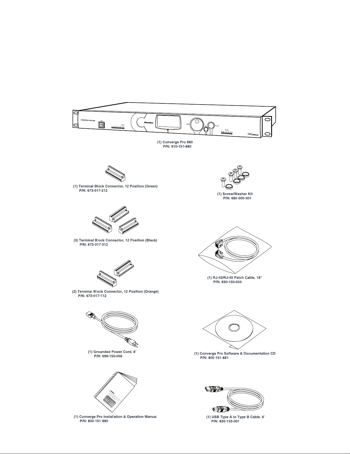
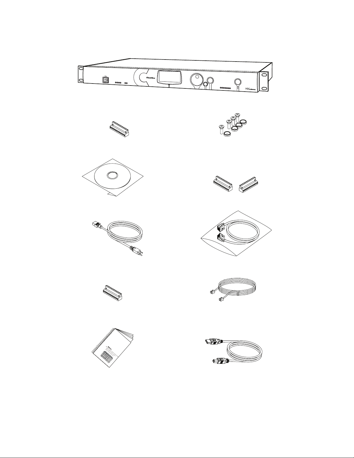
UNPACKING
Use the illustrations below to verify that you received all components for your CONVERGE Pro product. ClearOne
is not responsible for product damage incurred during shipment. Inspect your shipment carefully for obvious signs
of damage. If the shipment appears damaged, retain the original boxes and packing material for inspection by the
carrier, and contact them immediately.
CONVERGE Pro 880 Package Contents
20
Page 26
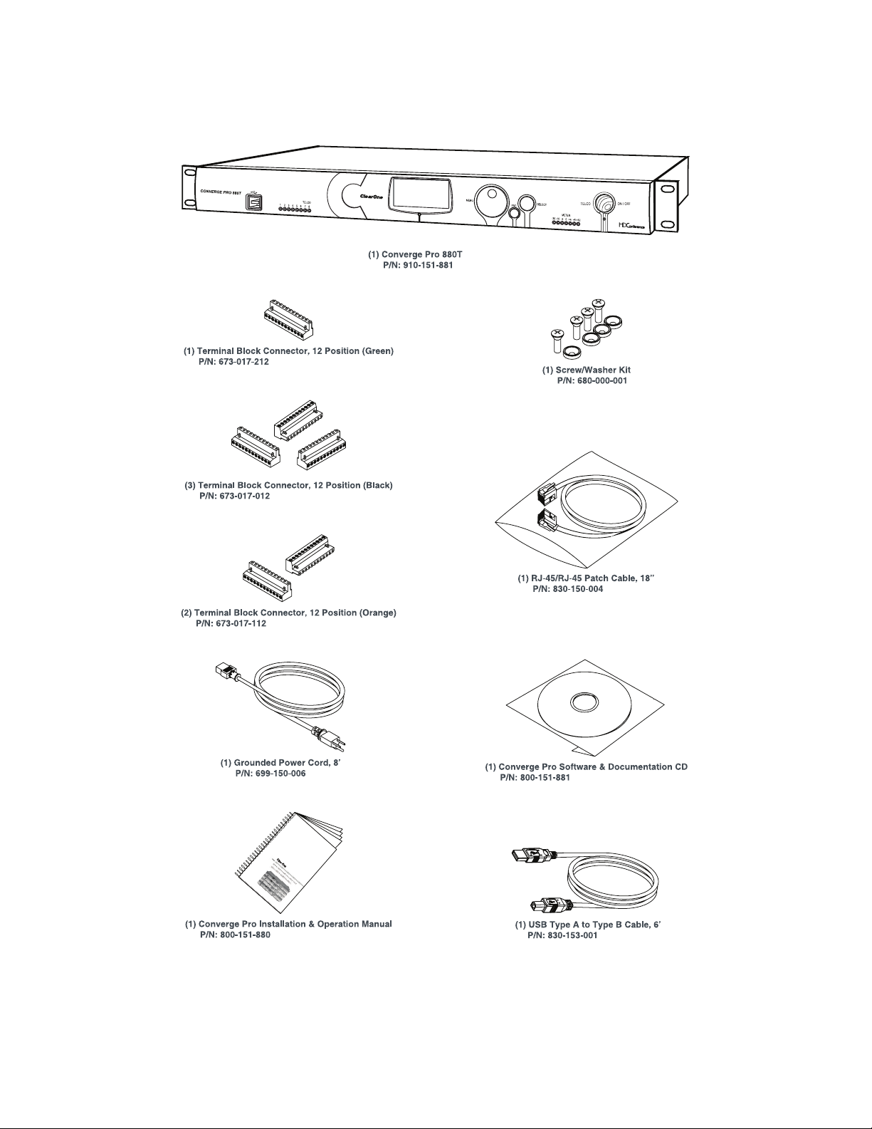
CONVERGE Pro 880T Package Contents
21
Page 27
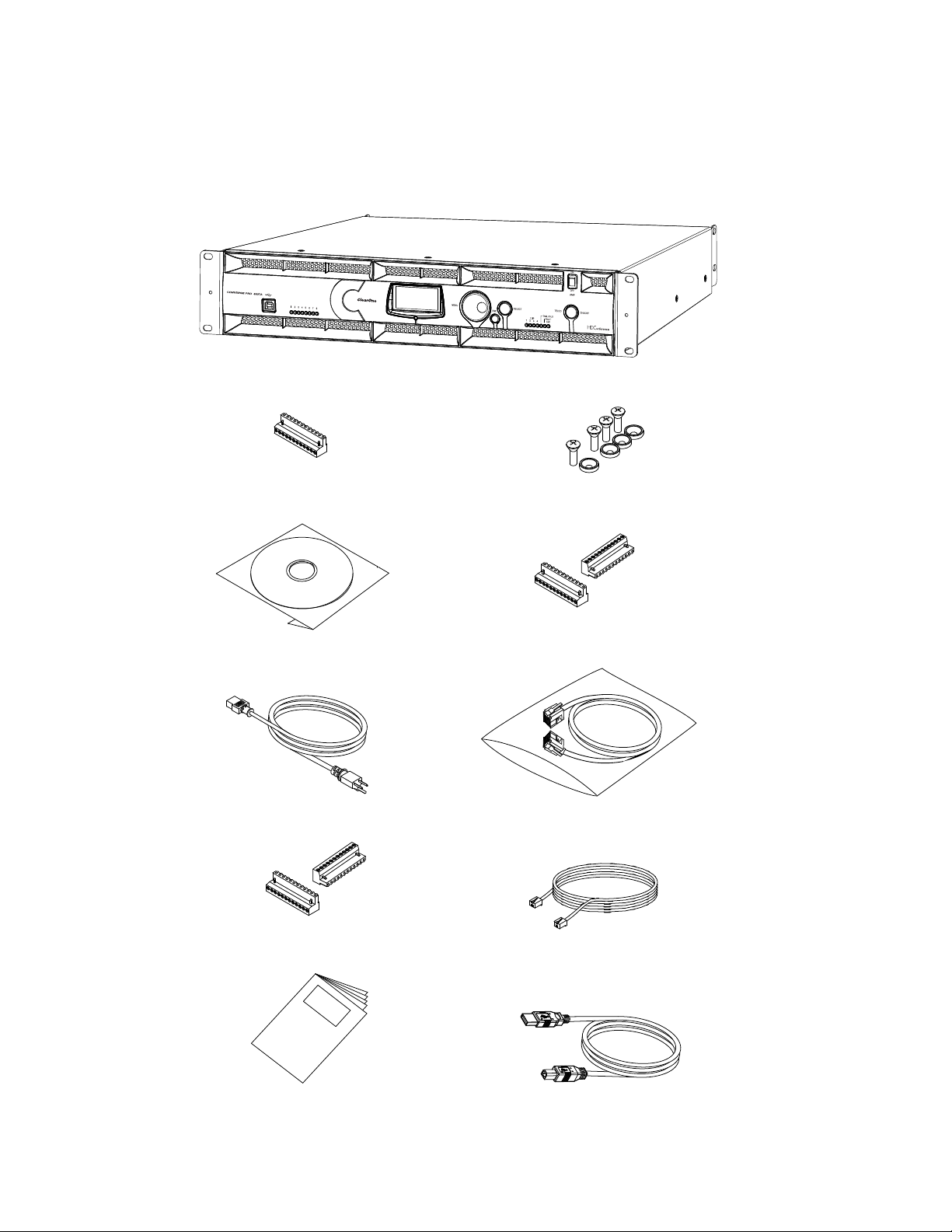
CONVERGE Pro 880TA Package Contents
Converge Pro 880TA Packing Contents
CONVERGE PRO 880TA (QTY 1)
CONN, TERM BLOCK/F 12 POS GREEN
673-017-212 (QTY 1)
CD, CONVERGE PRO PRODUCT FAMILY
800-151-881 (QTY 1)
PWR CORD, MOLDED 6' BLK 3 COND
699-150-006 (QTY
CONN, TERM BLOCK/F 12 POS ORANGE
673-017-112 (QTY 2)
1)
SCREW/WASHER ACC KIT, RACK DECOR 4EA BLK
680-000-001 (QTY 1)
CONN, TERM BLOCK/F 12 POS BLACK
673-017-012 (QTY 2)
CABLE ASSEMBLY, RJ45/RJ45 18"
830-150-004 (QTY 1)
CABLE ASSY, TELEPHONE 12FT.
830-000-012 (QTY 1)
22
MANUAL, CONVERGE 840T
800-151-880 (QTY 1)
CABLE ASSY, USB A-B TYPE 6FT
830-153-001 (QTY 1)
Page 28
CONVERGE Pro 840T Package Contents
CONVERGE PRO 840T
(1) Terminal Block Connector, 12 Position (Green)
P/N: 673-017-212
(1) Software & Documentation CD
P/N: 800-151-881
1 2 3 4
TELCO
TX
RX
(1) Converge Pro 840T
P/N: 910-151-840
MENU
(2) Terminal Block Connector, 12 Position (Black)
P/N: 673-017-012
SELECT
ESC
-30-10 -4 0
(1) Screw/Washer Kit
P/N: 680-000-001
TELCO
METER
ON/OFF
+4 +8+12
(1) Grounded Power Cord, 8’
P/N: 699-150-006
(1) Terminal Block Connector, 12 Position (Orange)
P/N: 673-017-112
(1) Installation & Operation Manual
P/N: 800-151-880
(1) RJ-45/RJ-45 Patch Cable, 18”
P/N: 830-150-004
(1) Telephone Cable 12’
P/N:830-000-012
(1) USB Type A to Type B Cable, 6’
P/N: 830-153-001
23
Page 29
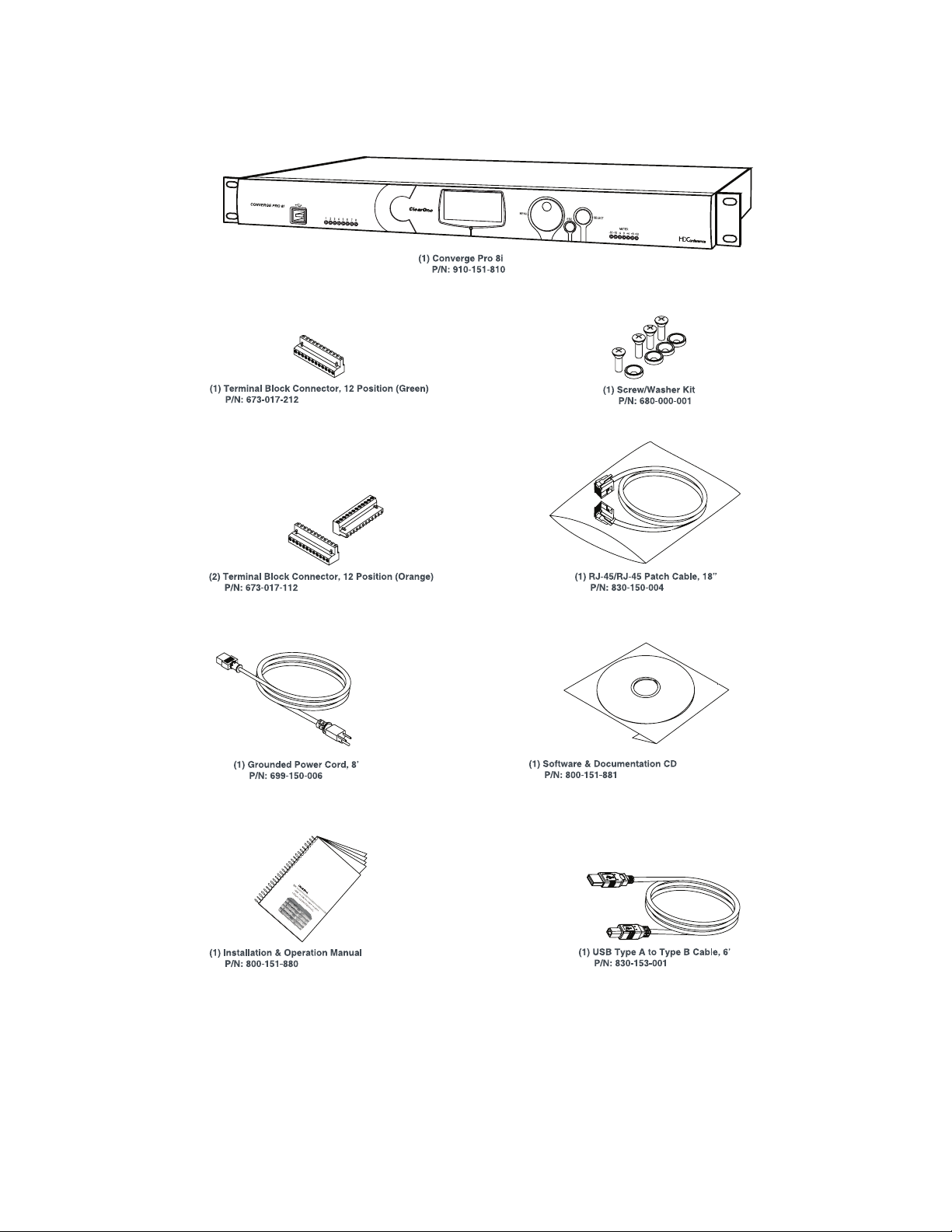
CONVERGE Pro 8i Package Contents
24
Page 30
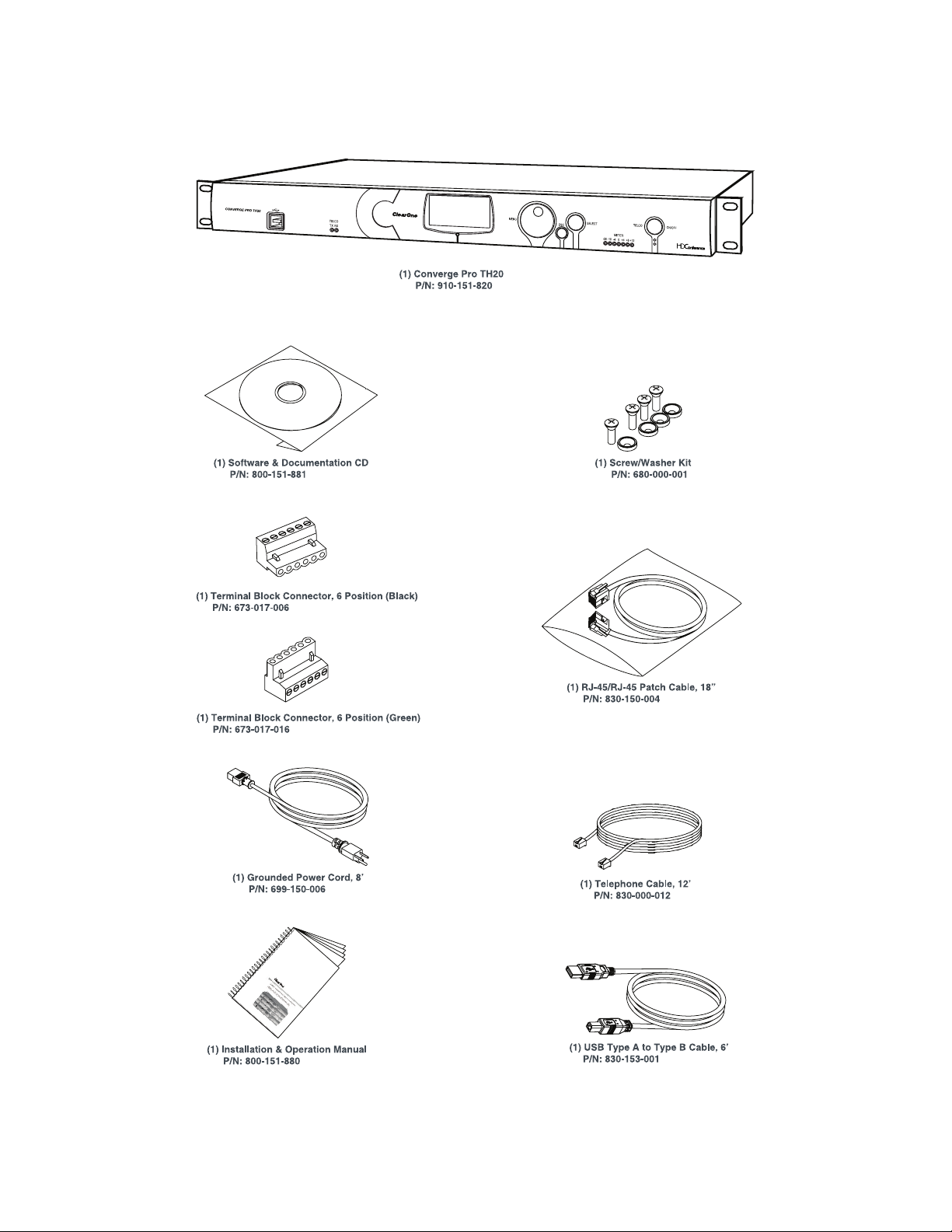
CONVERGE Pro TH20 Package Contents
25
Page 31

CONVERGE Pro VH20 Package Contents
V
26
(1) RJ-45/RJ-45 Cable Assembly, 7’
P/N: 830-000-023L
Page 32

CONVERGE Pro SR1212 Package Contents
27
Page 33

CONVERGE Pro SR1212A Package Contents
Converge SR 1212A Packing Contents
CONVERGE SR 1212A (QTY 1)
CONN, TERM BLOCK/F 12 POS GREEN
673-017-212 (QTY 1)
CD, CONVERGE PRO PRODUCT FAMILY
800-151-881 (QTY 1)
PWR CORD, MOLDED 6' BLK 3 COND
699-150-006 (QTY
CONN, TERM BLOCK/F 12 POS ORANGE
673-017-112 (QTY 2)
1)
SCREW/WASHER ACC KIT, RACK DECOR 4EA BLK
680-000-001 (QTY 1)
CONN, TERM BLOCK/F 12 POS BLACK
673-017-012 (QTY 2)
CABLE ASSEMBLY, RJ45/RJ45 18"
830-150-004 (QTY 1)
CABLE ASSY, USB A-B TYPE 6FT
830-153-001 (QTY 1)
28
MANUAL, CONVERGE 840T
800-151-880 (QTY 1)
Page 34

CONVERGE USB Package Contents
CONVERGE USB
910-151-806 (QTY 1)
QUICK START GUIDE, CONVERGE USB
800-151-806 (QTY 1)
CABLE ASSEMBLY, RJ45/RJ45 25"
830-001-025L (QTY 1)
POWER SUPPLY USB
551-153-500-01G (QTY 1)
CONNECT TERMINAL BLOCK/F 6 POS
673-017-006 (QTY 1)
CABLE ASSY, USB A-B TYPE 6FT
830-153-001 (QTY 1)
29
Page 35

CONNECT CobraNet/AVB Package Contents
T
CONNECT CobraNet/AVB
910-151-805 (QTY 1)
910-151-804 (QTY 1)
QUICK START GUIDE, CONNECT Cobranet/AVB
800-000-000-20-01 (QTY 1)
or
POWER SUPPLY USB
551-153-500-01G (QTY 1)
CABLE ASSEMBLY, RJ45/RJ45 25"
830-001-025L (QTY 1)
30
Page 36

Beamforming Microphone Array
The Beamforming Microphone Array requires a separately ordered PoE power supply and cable kit and a ceiling
mount kit as listed below:
• 910-001-003: Beamforming Microphone Array with 4 cable retention clips
• 910-001-004: PoE Power Supply & Cables Kit for Beamforming Microphone Array
• 910-001-005-12: Ceiling Mount kit with 12-inch spanner for Beamforming Microphone Array
• 910-001-005-24: Ceiling Mount kit with 24-inch spanner for Beamforming Microphone Array
31
Page 37

CONTROLS AND CONNECTIONS
BD
BD
H I
Refer to the following diagrams and descriptions for CONVERGE Pro front panel controls and back panel
connectors.
CONVERGE Pro Front Panels
CONVERGE Pro 880 Front Panel
AC
CONVERGE PRO 880
12345678
CONVERGE Pro 880T Front Panel
CONVERGE Pro 880TA Front Panel
A B C D E F
ClearOne
Converge 880
11: CONVERGE880-77
IPA: 192.168.1.1
1.0.00
EF G
SELECTMENU
ESC
-30 -10 -4 0+4+8+12
G
METER
I
H
SELECTMENU
1 2 3 4 5 6 7 8
ESC
CONVERGE Pro 840T Front Panel
AC
ClearOne
CONVERGE PRO 840T
1234 TX RX
TELCO
Converge 840T
32: CONVERGE840T-F0
IPA: 192.168.1.2
1.0.00
EF G
SELECTMENU
ESC
-30 -10 -4 0+4+8+12
METER
TELCO ON / OFF
32
Page 38

CONVERGE Pro 8i Front Panel
BD
H I
BD
AC
CONVERGE PRO 8i
12345678
CONVERGE Pro TH20 Front Panel
ACDEFG
CONVERGE PRO TH20
TELCO
TX RX
CONVERGE Pro VH20 Front Panel
A C D E F G
ClearOne
Converge 8i
A6: CONVERGE8i-1C
IPA: 192.168.1.4
1.0.00
ClearOne
Converge TH20
2F: CONVERGETH20-3A
IPA: 192.168.1.3
1.0.00
EF G
SELECTMENU
ESC
ESC
-30 -10 -4 0+4+8+12
SELECTMENU
-30 -10 -4 0+4+8+12
METER
METER
TELCO ON / OFF
CONVERGE PRO VH20
TELCO
TX RX
SELECTMENU
ESC
-30 -10 -4 0 +4 +8+12
METER
TELCO ON / OFF
H I
CONVERGE Pro SR1212 Front Panel
AC
ClearOne
Converge SR1212
CONVERGE PRO SR1212
12345678
G7: CONVERGE880-6F
IPA: 192.168.1.1
1.0.00
EF G
SELECTMENU
ESC
-30 -10 -4 0+4+8+12
METER
33
Page 39

CONVERGE Pro SR1212A Front Panel
A B C D E F G H
SELECTMENU
1 2 3 4 5 6 7 8
ESC
CONVERGE Pro Front Panel Control Descriptions
A. USB Type B Port: Provides convenient front panel connectivity for laptops and PCs.
B. Microphone-On LEDs: Indicate microphone gate status and mute state.
C. LCD Display: Shows model number, unit name, IP address, firmware version, menu pages, menu options,
configuration settings, and parameter values.
D. Menu Dial: Navigates the CONVERGE Pro LCD programming menu and enables you to modify basic
configuration settings.
E. ESC Button: Returns you to the previous screen on the LCD display.
F. Select Button: Displays the CONVERGE Pro LCD programming menu and selects the highlighted option.
G. LED Bar Meter: Displays the audio level of a selected input, output, processing, or fader channel. Default
meters: 880-Output 12, 880T-Output 12 , 840T-Output 8, 8i-Mic 1, TH20-Telco Tx, VH20-VoIP Tx, SR1212Output 12.
• AMP Fault Indicator LEDs(880TA, SR1212A): Indicates amplifier faults:
» 1-4 indicates clip
» 5 indicates thermal overload
» 6 indicates fault
» 7 indicates fan on/off
• Telco/VoIP Tx Rx Indicators (840T, TH20, VH20): Indicates transmit and receive activity during
Telco/VoIP calls.
H. Amplifier On/Off Switch (880TA, SR1212A): Turns power to the amplifiers on or off.
NOTE (880TA, SR1212A): This does NOT disconnect power from the AC mains. To disconnect unit
power from the mains, disconnect the unit’s power cord from the mains socket. To reconnect power, plug
the unit’s power cord into the mains socket following all safety instructions and guidelines.
I. Telco On/Off Button & LEDs: This button connects/disconnects the communications line attached to the
device while the LEDs indicate the connection status of the attached line (840T, TH20, VH20 (VoIP only),
880T, 880TA ).
34
Page 40

CONVERGE Pro Rear Panels
123457896
CONVERGE Pro 880 Rear Panel
VOLTAGE RANGE 100-240 VAC 2A
FREQUENCY 50Hz / 60Hz
MIC / LINE
1234 1234
5678 5678
LINE OUT
9101112
CONVERGE Pro 880T Rear Panel
CONVERGE Pro 880TA Rear Panel
1
R
,
2 3 4
1 2 3 4 1 2 3 4
5 6 7 8
5 6 7 8
+-
LINE IN
LINE OUT
LINE IN
5 6 7 8
LINE OUT
9101112
LINK IN
LINK OUT
6
PC
RS-232
7
CONTROL / STATUS
8
A
B
LAN
9
11
CONVERGE Pro 840T Rear Panel
123457896
VOLTAGE RANGE 100-240 VAC 2A
FREQUENCY 50Hz / 60Hz
MIC / LINE
1234 1234
+-
5678 5678
CONVERGE Pro 8i Rear Panel
12 47896
VOLTAGE RANGE 100-240 VAC 2A
FREQUENCY 50Hz / 60Hz
MIC / LINE
1234
5678
9101112
35
10
LINE INLINE OUT LINE OUT
10
+-
LINE IN
LINK IN
LINK OUT
LINK IN
LINK OUT
RS-232
RS-232
12
CONTROL / STATUS
CONTROL / STATUS
PC
TELCO
SET
A
B
LINE
LAN
11
PC
A
B
LAN
Page 41

CONVERGE Pro TH20 Rear Panel
1457896
VOLTAGE RANGE 100-240 VAC 2A
FREQUENCY 50Hz / 60Hz
LINE IN LINE OUT
12 12
LINK IN
LINK OUT
RS-232
CONTROL / STATUS
CONVERGE Pro VH20 Rear Panel
1 4 5 6 7 8 9
VOLTAGE RANGE 100-240 VAC 2A
FREQUENCY 50Hz / 60Hz
LINE IN LINE OUT
1 2 1 2
LINK IN
LINK OUT
RS-232
CONTROL / STATUS
CONVERGE Pro SR1212 Rear Panel
123457896
VOLTAGE RANGE 100-240 VAC 2A
FREQUENCY 50Hz / 60Hz
MIC / LINE
1234 1234
5678 5678
LINE OUT
+-
LINE IN
9101112
LINE OUT
9101112
LINK IN
LINK OUT
RS-232
CONTROL / STATUS
PC
TELCO
SET
A
B
LINE
LAN
11
PC
TELCO
SET
A
B
A
B
LINE
LAN
PC
LAN
CONVERGE Pro SR1212A Rear Panel
1
R
,
2 3 4 6
1 2 3 4 1 2 3 4
5 6 7 8
5 6 7 8
LINE OUT
LINE IN
5 6 7 8
10
7
8
9
12
36
Page 42

CONVERGE Pro Rear Panel Connectors
1. AC Power: IEC connector, 100 – 240VAC auto-adjusting, 50/60Hz.
Warning: This equipment must be connected to an AC mains socket outlet with a protective
earthing connection. The third prong of this connector (ground) is an important safety feature. Do not
attempt to disable this ground connection by using an adaptor or other method.
2. Mic/Line Inputs: Mini-terminal push-on block connector for any combination of microphone and/or line
level inputs. (CONVERGE Pro 880: 8 inputs. CONVERGE Pro 880T: 8 inputs. CONVERGEPro 880TA: 8
inputs. CONVERGE Pro 840T: 4 inputs. CONVERGE Pro 8i: 8 inputs. CONVERGE Pro TH20, VH20: 0
inputs. CONVERGE SR1212: 8 inputs. CONVERGE SR1212A: 8 inputs.)
3. Line Outputs: Mini-terminal push-on connector for line-level outputs (880, 880T, 880TA, 840T, SR 1212, SR
1212A).
4. Line Inputs: Mini-terminal push-on block connector for line level inputs only. (CONVERGE Pro 880: 4
inputs. CONVERGE Pro 880T: 4 inputs. CONVERGE Pro 880TA: 4 inputs. CONVERGE Pro 840T: 4 inputs.
CONVERGE Pro 8i: 4 inputs. CONVERGE Pro TH20, VH20: 2 inputs. CONVERGE SR1212: 4 inputs.
CONVERGE SR1212A: 4 inputs.)
5. Line Outputs: Mini-terminal push-on block connector for line-level outputs (880, 880T, 840T, TH20, VH20,
SR1212).
6. Link In and Link Out Ports: Two RJ-45 E-bus (expansion bus) connectors used to connect multiple
CONVERGE Pro units together to create a site. You can connect up to twelve CONVERGE Pro
840T/880/880T/880TA/8i/SR1212/SR212A units, up to 16 CONVERGE Pro TH20/VH20 units, or any
combination thereof, where the total number of microphone inputs does not exceed 96. Maximum cable
length is 200 feet using Category 5 unshielded twisted pair cable.
WARNING: Use the Link In and Link Out ports with CONVERGE Pro Devices or Beamforming
Microphone Array ONLY. Connecting ANY other devices to the Link In and Link Out ports,
including ClearOne XAP or PSR1212 products, or Power Over Ethernet (PoE) devices, will result
in severe equipment damage.
7. RS-232 Serial Port: Female DB9 connector for connecting to a laptop, computer, or remote control serial
devices (such as AMX and Crestron controllers).
NOTE: CONVERGE Console software cannot connect via the RS-232 port; use USB or
Ethernet.
8. Control/Status A and B Ports: Two female DB25 connectors used for GPIO interactions between
CONVERGE Pro devices and external control devices (such as wall switches and push-to-talk
microphones). This enables external devices and controller software to access the CONVERGE Pro
command set, including common functions such as volume control, muting, room combining, and preset
changes.
9. PC and LAN Ethernet Ports: Two RJ-45 10/100Mbps auto-sensing Ethernet ports. The LAN port connects
CONVERGE Pro devices to a network. The PC port provides a pass-through network connection for use
with a standard (not crossover) patch cable. The LEDs adjacent to each port indicate connection status
and packet traffic activity.
10. Speaker Posts (880T, 840T)/Amplifier Terminal Block (880TA, SR1212A):
• 880T,840T--Twopost/bananaplugconnectorsusedtoconnectanexternalspeaker(4Ω–16Ω).
Internal power amplifiers eliminate the need for an external power amplifier.
37
Page 43

• 880TA,SR1212A--8speakerterminalsusedtoconnectanexternalspeaker(8Ω).Four,35Watt
internal power amplifiers eliminate the need for an external power amplifier.
NOTE: To reduce risk of electrical shock and damage to equipment, never connect wiring or
external equipment while the amplifier is power is on. Class 2 wiring is required. Maintain
the correct polarity (+/-) on output connectors. (For example: Channel 1 positive (+)
speaker lead connects to amplifier’s channel 1 positive terminal. Channel 1 negative (-)
speaker lead connects to amplifier’s channel 1 negative terminal. Repeat this procedure
for each channel.
11. Telco Line and Telco Set Ports: Two RJ-11 connectors telephone ports. The Telco Line port connects an
analog telephone line to CONVERGE Pro devices. The Telco Set port provides a pass-through connection for
telephone handsets (880TA, 880T, 840T, TH20).
NOTE: The Telco Set port is not available for use when the telephone hybrid is off-hook.
12. Amplifier Terminal Block (880TA, SR1212A): 12 speaker terminals used to connect an external speaker
(70/100 v). Four, 35 Watt internal power amplifiers eliminate the need for an external power amplifier.
NOTE: To reduce risk of electrical shock and damage to equipment, never connect wiring or
external equipment while the amplifier is power is on. Class 2 wiring is required. Maintain
the correct polarity on output connectors. (For example: Channel 1 70/100V speaker
lead connects to amplifier’s channel 1 70V or 100V terminals. Channel 1 GND (or
Common) speaker lead connects to amplifier’s channel 1 GND terminal. Repeat this
procedure for each channel.
38
Page 44

Beamforming Microphone Array Connections and Controls
Refer to the following diagrams and descriptions for Beamforming Microphone Array connections and controls.
Beamforming Microphone Array Connections
1. Link In and Link Out Ports: Two RJ-45 E-bus (expansion bus) connectors are used to connect multiple
CONVERGE Pro units or to daisy-chain Beamforming Microphone arrays together to create a site. 3 arrays
per CONVERGE Pro unit are supported and up to 16 Beamforming Microphone Arrays can be daisychained in the site.
WARNING: Use the Link In and Link Out ports ONLY with CONVERGE Pro and/or Beamforming
Microphone Array devices. Connecting ANY other devices to the Link In and Link Out ports,
including ClearOne XAP or PSR1212 products, or Power Over Ethernet (PoE) devices, will result
in severe equipment damage.
2. Power over Ethernet Connector(PoE): The PoE connection is only for power, not control. Power must
be provided through a standard Power-over-Ethernet switch or through an external PoE power supply for
individual units; no daisy-chain power is allowed.
3. Device ID Selector: Set each Beamforming Microphone Array unit within the site to a unique ID using the
Device ID selector rotary switch on the back of the unit. (Range 0-F)
Beamforming Microphone Array Controls
The Beamforming Microphone Array is controlled mainly through CONVERGE Console except for mute buttons on
the device that toggle the microphone array mute on and off. The mute buttons illuminate red when the microphone
array is muted and blue when the array is unmuted. This action can also be software controlled through
CONVERGE Console.
39
Page 45

CONNECT Cobranet/AVB Connections and Controls
Refer to the following diagrams and descriptions for CONNECT CobraNet/AVB connections and controls.
CONNECT CobraNet and CONNECT AVB Connections
Set each CONNECT CobraNet and CONNECT AVB unit to a unique ID using the Device ID selector rotary switch
on the back of the unit. (Range 0-7) Each CONNECT unit in any site needs a unique Device ID. Only 8 units are
allowed in any site.
Device ID
Switch
5V DC
Power
Input
E-bus LINK OUT
(Not required if the bridge
is at the end of the stack)
CONVERGE Pro/SR
CONNECT
Network Bridge
AVB
CONNECT
Network Bridge
Link IN
Link OUT
Link IN
CobraNet
AVB
Network
Connection
CobraNet
Network
Connection
AVB
Ethernet LAN
Network 1
CobraNet
Ethernet LAN
Network 2
Connecting CONVERGE Pro/SR units in different
rooms that are on different networks using
multiple CobraNet
and AVB network bridges
E-bus LINK IN from Stack
Bridge connection
to Ethernet Network
(CobraNet shown)
AVB
Network
Connection
CobraNet
Network
Connection
CONVERGE Pro/SR
Link IN
CONNECT
Network Bridge
CONNECT
Network Bridge
CobraNet
Link IN
CONVERGE Pro/SR
AVB
CONNECT CobraNet and CONNECT AVB Control
The CONNECT CobraNet and the CONNECT AVB network audio bridges are controlled mainly through
CONVERGE Console where configuration is made and device identification (set matching the Device ID switch) is
established in the stack.
40
Page 46

CONVERGE USB
Refer to the following diagrams and descriptions describe the CONVERGE USB connections and controls when
used as an USB interface and as and E-bus extender.
CONVERGE USB Interface Connections
Connect each CONVERGE USB unit to the site via the E-bus connections.
CONVERGE Pro Unit
E-bus
From
LINK Out
COLLABORATE Room
VC Endpoint
or
Laptop/PC Running
UC Application
E-bus LINK IN from Stack
12V DC
Power
Input
E-bus LINK OUT
(Not required if unit is at end of stack)
USB
Audio
Transmit and Receive
USB Connection to PC/Laptop or COLLABORATE Room
(Not required if used as an E-bus Extender)
CONVERGE USB
E-bus To
LINK In
Terminal Block for Channel Selection
(Not required if used as an E-bus Extender)
The E-bus channels upon which the Tx/Rx audio will be available is determined by the jumpers placed in the
Channel Selection Terminal Block.
No
Connector
Tx channel - K
Rx channel - L
Tx channel - M
Rx channel - N
Tx channel - O
Rx channel - P
Tx channel - Q
Rx channel - R
Routing the CONVERGE USB Interface Connections
Using CONVERGE Console, route each CONVERGE USB Tx/Rx signal within the site to match the E-bus
connections as selected by the terminal block. This is done on the Matrix screen for the site.
In the example below a terminal block jumper is between pins 1 and 6, so the CONVERGE Pro channels are M for
transmit and N for receive. These must then be routed to the desired inputs and outputs. The following two screen
captures show audio from the CONVERGE USB on Channel M going to Output 8, and Channel N receiving audio
from Input 9 then sending it to the CONVERGE USB.
Tx channel - M
Rx channel - N
41
Page 47

Using the CONVERGE USB as an E-bus Extender
The CONVERGE USB application as an E-bus extender can, for example, be up to 200 feet from the stack, then
re-send the E-bus signals for up to another 200 feet to the next E-bus component.
The following diagram illustrates the use of the CONVERGE USB as an E-bus extender.
CONVERGE Pro Unit
E-bus
From
LINK Out
E-bus To
LINK In
(Up to 200 Ft. Max. Length) (Up to 200 Ft. Max. Length)
CONVERGE USB
CONVERGE Pro Unit
E-bus
From
LINK Out
NOTE: Link Channel Selection and routing is NOT required when the CONVERGE USB is used
only as an E-bus extender with no USB Tx/Rx channels used.
E-bus To
LINK In
42
Page 48

CHAPTER 2: EXPANSION BUS & LCD PROGRAMMING
VOLTAGE RANGE 100-240 VAC 2A
FREQUENCY 50Hz / 60Hz
MIC / LINE
1234
LINE IN
9101112
5678
+-
LINK IN
LINK OUT
RS-232
CONTROL / STATUS
A
B
PC
LAN
VOLTAGE RANGE 100-240 VAC 2A
FREQUENCY 50Hz / 60Hz
MIC / LINE
12341234
LINE INLINE OUT LINE OUT
5678 5678
+
-
LINK IN
LINK OUT
RS-232
CONTROL / STATUS
A
B
PC
LAN
TELCO
LINE
SET
VOLTAGE RANGE 100-240 VAC 2A
FREQUENCY 50Hz / 60Hz
MIC / LINE
12341234
LINE IN
LINE OUT
9101112
LINE OUT
9101112
56785678
+
-
LINK IN
LINK OUT
RS-232
CONTROL / STATUS
A
B
PC
LAN
VOLTAGE RANGE 100-240 VAC 2A
FREQUENCY 50Hz / 60Hz
12 12
LINE IN LINE OUT
LINK IN
LINK OUT
RS-232
CONTROL / STATUS
A
B
PC
LAN
TELCO
LINE
SET
Converge Pro 840T
Link Out
Link In
Link Out
Link Out
Link In
Link In
Converge Pro TH20Converge Pro 8i
Converge Pro 880
EXPANSION BUS
The Expansion Bus (E-bus) allows you to connect multiple CONVERGE/CONVERGE-Pro units together to create
powerful audio and conferencing solutions for any size venue. The E-bus is a proprietary digital audio bus that
provides control and audio data links between devices.
Expansion Bus Connections
Using the E-bus Link In and Link Out ports, you can connect up to 34 CONVERGE Pro 880/880T/880TA/840T/8i and
CONVERGE SR1212/SR1212A units, and 16 Beamforming Microphone Arrays, and up to 16 CONVERGE Pro TH20
and VH20 units, where the total number of microphone inputs does not exceed 96.
Connect units in daisy-chain fashion (as shown below) using the 18” straight-through patch cable included with
each unit (Part # 830-150-004) . For larger distances between units, use CAT 5 twisted pair cable with RJ-45
connectors. The maximum cable length between connected units is 200 feet (61 meters).
Converge Pro 840T
VOLTAGE RANGE 100-240 VAC 2A
FREQUENCY 50Hz / 60Hz
VOLTAGE RANGE 100-240 VAC 2A
FREQUENCY 50Hz / 60Hz
MIC / LINE
12341234
MIC / LINE
1234
5678
+
-
LINE INLINE OUT LINE OUT
5678 5678
Link Out
Link In
+-
LINE IN
9101112
LINK IN
RS-232
LINK OUT
LINK IN
RS-232
LINK OUT
CONTROL / STATUS
CONTROL / STATUS
PC
TELCO
SET
LINE
A
B
LAN
PC
A
B
LAN
Converge Pro 880
VOLTAGE RANGE 100-240 VAC 2A
FREQUENCY 50Hz / 60Hz
MIC / LINE
12341234
56785678
Converge Pro TH20Converge Pro 8i
VOLTAGE RANGE 100-240 VAC 2A
FREQUENCY 50Hz / 60Hz
LINE OUT
-
+
LINE IN
9101112
9101112
LINE IN LINE OUT
12 12
Link In
LINK IN
LINE OUT
RS-232
LINK OUT
CONTROL / STATUS
PC
A
B
LAN
Link Out
Link In
LINK IN
RS-232
LINK OUT
CONTROL / STATUS
PC
TELCO
SET
LINE
A
B
LAN
Link Out
Audio and Control Buses
The E-bus allows audio routing between source devices and destination devices on the E-bus network. The E-bus
contains 18 independent digital audio buses labeled I–Z, which can route mic or line inputs in any combination
across the E-bus network. The E-bus also contains four PA adapt/acoustic echo cancellation reference buses, six
global gating buses, and one control bus.
S-Z Buses: These eight buses are line input mixer buses. They are used to route auxiliary audio, such as from a CD
player or VCR, to and from other units on the network. These buses are also used as mic mixer buses when NOM
count is not required.
I-R Buses: These ten audio buses are generally used for routing microphone audio between CONVERGE/
CONVERGE Pro devices. Information about the number of gated microphones (NOMcount) and other relevant
information for the microphone mixers are tracked for microphones routed to these buses. By default, all
microphones are routed to the O bus.
PA Adapt/Acoustic Echo Cancellation Reference Buses: These buses allow an input from a CONVERGE/
CONVERGE Pro device to reference an output on another linked device for AEC and PA Adaption. See AEC
Reference/PA Adapt Reference and AEC for more information.
Global Gating Groups A-F: These buses are microphone gating groups that support first-mic priority, maximum
number of mics, etc. and work across all linked CONVERGE/CONVERGE Pro devices. Unlike the audio buses, they
contain only mic status and gate parameters. See the Gating and Gating Group topics for more information.
Control Bus: The control bus is an independent channel from the E-bus’s audio channel. This allows control
information to pass even if the units are not using the audio link. All models support the use of the CONVERGE/
CONVERGE Pro serial command set through the control bus.
43
Page 49

DEVICE IDS
Device IDs provide unique identifiers for all units that are linked together using the E-bus. After making Expansion
Bus connections, you must set a unique Device ID number for all units of the same Device Type on the E-bus.
Device Types and IDs
Device Types and Device IDs by model are as follows:
Model Device Type Device ID Range
880 1 0-B
TH20 2 0-F
VH20 E 0-F
840T 3 0-B
8i A 0-B
880T D 0-B
880TA H 0-B
SR1212 G 0-B
SR1212A I 0-B
Beamforming
Microphone
Array
N 0-F
NOTE: All models ship from the factory with a default DID of 0.
Assigning Device IDs
Use the following procedure to assign device IDs using the front panel controls:
1. Press the Select button on the front panel. The CONVERGE Menu appears.
CONVERGE MENU
Channels
2. Use the Menu Dial to highlight the Settings menu. Press the Select button. The Settings menu appears.
SETTINGS PAGE 1/2
RS232
Settings
PresetsMacros
Network
DefaultDID
44
Page 50

3. Use the Menu Dial to highlight DID. Press the Select button. The Device ID menu appears.
DEVICE ID MENU
0
1
2
3
4
5
6
4. Use the Menu Dial to highlight the desired value. Press the Select button to select it.
5. The Change DID Menu prompt appears. Choose Yes to set the selected DID value, or No to return to the
Device ID menu.
CHANGING DID MENU
Change DID to
4?
Yes
No
6. Press Esc until to return to the Settings menu.
7. Repeat this process for each device on the E-bus network.
NOTE: You can also set Device IDs in the Unit Properties screen in Console (when
disconnected). However, DID assignments made in Console must match the DID
assignments made using the front panel.
Assigning Beamforming Microphone Array Device IDs
Set each Beamforming Microphone Array unit within the site to a unique ID using the Device ID selector rotary
switch on the back of the unit. (Range 0-F)
45
Page 51

LCD PROGRAMMING OVERVIEW
LCD Programming allows you to make simple configuration adjustments using front panel controls (shown below).
I
A B C D E F
ESC
1 2 3 4 5 6 7 8
G
SELECTMENU
A. USB Type B Port: Provides convenient front panel connectivity for laptops and PCs.
B. Microphone-On LEDs: Indicate microphone gate status and mute state.
C. LCD Display: Shows model number, unit name, IP address, firmware version, menu pages, menu options,
configuration settings, and parameter values.
D. Menu Dial: Navigates the CONVERGE Pro LCD programming menu and enables you to modify basic
configuration settings.
E. ESC Button: Returns you to the previous screen on the LCD display.
H
F. Select Button: Displays the CONVERGE Pro LCD programming menu and selects the highlighted option.
G. LED Bar Meter: Displays the audio level of a selected input, output, processing, or fader channel. Default
meters: 880-Output 12, 880T-Output 12 , 840T-Output 8, 8i-Mic 1, TH20-Telco Tx, VH20-VoIP Tx, SR1212Output 12.
• AMP Fault Indicator LEDs(880TA, SR 1212A): Indicates amplifier faults:
» 1-4 indicates clip
» 5 indicates thermal overload
» 6 indicates fault
» 7 indicates fan on/off
• Telco/VoIP Tx Rx Indicators (840T, TH20, VH20): Indicates transmit and receive activity during
Telco/VoIP calls.
H. Amplifier On/Off Switch (880TA, SR 1212A): Turns power to the amplifiers on or off.
NOTE (880TA, SR 1212A): This does NOT disconnect power from the AC mains. To disconnect unit power
from the mains, disconnect the unit’s power cord from the mains socket. To reconnect power, plug the
unit’s power cord into the mains socket following all safety instructions and guidelines.
46
Page 52

I. Telco On/Off Button & LEDs: This button connects/disconnects the communications line attached to the
Channels
device while the LEDs indicate the connection status of the attached line (840T, TH20, VH20 (VoIP only),
880T, 880TA ).
In addition to making configuration adjustments from the front panel, you can also run macros and execute presets.
For more information on using front panel controls, see Controls and Connections.
Adjusting LCD Menu Parameters
Use the following procedure to adjust LCD Menu parameters:
1. Press the Select button to access the CONVERGE Menu.
2. Scroll to the parameter you want to adjust using the Menu Dial.
3. Press the Select button to select the parameter. The parameter will stop flashing when selected.
4. Select the value for the parameter using the Menu Dial.
5. Press the Select button to save the parameter value. To discard the change and return to the previous menu,
press the Esc button.
NOTE: Use the Console software in Configuration Mode for advanced configuration tasks.
LCD Menu Tree
ClearOne
Converge 840T
32: CONVERGE840T-F0
IPA: 192.168.1.2
1.0.00
CONVERGE MENU
Settings
PresetsMacros
Macros
Mics
Inputs
Outputs
Process
Faders
Telco Tx
Telco Rx
Pwr Amp
Channels
Settings
RS-232
Network
DID
Default
Contrast
As shown above, the main menus on the LCD display are:
• Channels
• Settings
• Macros
• Presets
Macros
1-255
Presets
Presets
1-32
47
Page 53

LCD Default Display
When you power up a CONVERGE/CONVERGE Pro unit, the LCD display reads Initializing. If an error occurs,
contact ClearOne Technical Support. When initialization is complete, ClearOne CONVERGE[Model Number]
appears on the LCD panel, along with the device type, device ID, device name, IP address, and firmware revision
level as shown below.
ClearOne
Converge 840T
32: CONVERGE840T-F0
IPA: 192.168.1.2
1.0.00
To access the LCD menu, press the Select button. The CONVERGE Menu appears as shown below.
CONVERGE MENU
Channels
Settings
PresetsMacros
Model
DeviceType, ID, Name
IP Address
Firmware Level
Front Panel Lock
Using Console, you can create a PIN code and lock the front panel to prevent unauthorized access to LCD menu
functions. When the lock feature is enabled and the front panel is unlocked, it will automatically re-lock after 3
minutes of inactivity. See the Unit Properties topic for instructions on how to enable the lock feature.
For more information, see the Table of Contents for these related topics:
• Macros
• Presets
• Controls and Connections
• Console Configuration Mode
• Mic Input Settings
• Line Input Settings
• Telco/VoIP Rx Settings
• Telco/VoIP Tx Settings
• Processing Settings
• Output Settings
• LCD Channels Menu
• LCD Settings Menu
• LCD Macros Menu
• LCD Presets Menu
• Device IDs
• Unit Properties
48
Page 54

LCD CHANNELS MENU
The LCD Channels Menu allows you to adjust the gain level and turn mute on or off for all channels.
Accessing the Channels Menu
To access the Channels menu, press the Select button on the front panel, use the Menu Dial to select
Channels, and press the Select button.
The Channels menu appears as shown below:
CHANNELS PAGE 1/2
Mics
Channels menu options (i.e. channel types) include:
• Mics
• Inputs
• Outputs
• Process
• Faders
• Telco/VoIP Tx
• Telco/VoIP Rx
• Pwr Amp
Inputs
ProcessOutputs
After you select an option, a list of all available channels of that type is displayed. Use the Menu Dial to select the
channel you want to configure and press the Select button. The Channels display appears.
Channel Display
The channel display is identical for every channel type, with the exception of the channel ID and channel label, which
both vary depending on the channel selected.
As shown below, the display includes a peak-level meter, a peak dB reading, a gain level adjustment box, and a
mute selector.
Meter
Gain
1-Input 1
+0
dB Mute Off
dB
-50
49
Page 55

Setting Channel Gain and Mute
The procedure for setting gain and mute is the same for all channel types:
1. Use the Menu Dial to highlight Gain or Mute
2. Press the Select button
3. Select the desired value using the Menu Dial
4. Press the Select button to set the selected value
5. Press the Esc button to return to the Channels menu
NOTE: When mute is set to on for a mic input channel, the Microphone-On LED for that channel
illuminates red on the front panel.
For more information, see the Table of Contents for these related topics:
• LCD Programming Overview
• LCD Channels Menu
• LCD Settings Menu
• LCD Macros Menu
• LCD Presets Menu
• Controls and Connections
• Mic Input Settings
• Line Input Settings
• Output Settings
• Process Settings
• Fader Settings
• Telco/VoIP Tx Settings
• Telco/VoIP Rx Settings
• Pwr Amp
LCD SETTINGS MENU
The LCD Settings Menu allows you to configure serial port settings and Device IDs, view network IP settings,
change the LCD contrast level, and restore factory default settings for a unit.
Accessing the Settings Menu
To access the Settings menu, press the Select button on the front panel, use the Menu Dial to select Settings,
and press the Select button.
The Settings menu appears as shown below:
SETTINGS PAGE 1/2
RS232
Network
DefaultDID
50
Page 56

Settings menu options include:
• RS-232
• Network
• DID
• Default
• Contrast
• Version
• SIP*
*VH20 Only
These options are described in the following sections.
RS-232
There are two parameters in the RS-232 menu: Baud Rate and Flow Control. To change these settings, use the
following procedure:
1. Use the Menu Dial to highlight Baud Rate or Flow Control
2. Press the Select button
3. Select the desired value using the Menu Dial
4. Press the Select button to set the selected value
5. Press the Esc button to return to the Settings menu
You can also use the Comm tab of the Unit Properties screen to change these settings.
Baud Rate
This parameter allows you to set the baud rate to 9.6kbps, 19.2kbps, 38.4kbps, 57.6kbps, or 115.2kbps. The default
is 57.6 kbps. Select the baud rate you want to use, then press the Select button. A message appears on the LCD
display indicating the change is in progress, and another indicating the change is complete. When finished, the
display returns to the RS-232 sub-menu.
Flow Control (Hardware)
All models use the RTS and CTS pins on the RS-232 port to regulate the transmission and reception of data. You
can enable or disable flow control on the front panel, and set the flow control type in the Unit Properties window in
Console.
If you select On (default) from the front panel LCD menu, select Hardware as the flow control type in the Unit
Properties window. If you disable flow control on the front panel, select None in the Unit Properties window.
When None is selected, the unit ignores flow control, and the relies on the connected external control device to
ensure data is not lost.
NOTE: ClearOne recommends that you leave Flow Control enabled and connect all DB9 pins to
avoid communication errors.
Network
The Network submenu displays the unit name, IP address, Gateway, and Subnet Mask settings for the unit. You
cannot change any of these settings from the Network submenu. Use the Unit Properties screen in Console to
change these settings.
51
Page 57

DID
The DID submenu allows you to select a Device ID for the unit. Select the DID you want to use, press the Select
button. Answer Yes to the prompt to change the DID, or No to keep the existing setting.
You can also use the General tab of the Unit Properties screen in Console to change this setting when disconnected
from the unit. However, DID assignments made in Console must match DID assignments made using the front
panel.
Default
Default restores ALL settings to their factory default values. Answer Yes to the prompt to restore default settings, or
No to retain the existing settings.
Contrast
Contrast allows you to change the LCD contrast level. Use the Menu Dial to adjust the contrast level, then press
the Select button to save it.
Version
Version displays all relevant version data related to the device.
SIP
SIP Displays which Proxy Settings are currently enabled on the VH20.
For more information, see the Table of Contents for these related topics:
• LCD Programming Overview
• LCD Channels Menu
• LCD Macros Menu
• LCD Presets Menu
• Site Properties
• String Tab
• Unit Properties
LCD MACROS MENU
The LCD Macros Menu allows you to run macros from the front panel. To record Macros, use the Macro Tab in
Console.
Accessing the Macros Menu
To access the Macros menu, press the Select Button on the front panel, use the Menu Dial to select Macros, and
press the Select Button.
The Macro Menu appears as shown below:
MACRO MENU
1-Gain Adjust 7-8
2-UnProgrammed
3-UnProgrammed
4-UnProgrammed
5-UnProgrammed
6-UnProgrammed
7-UnProgrammed
52
Page 58

Executing Macros
Use the following procedure to run macros from the front panel LCD display:
1. Use the Menu Dial to highlight the macro you want to run
2. Press the Select button
3. Answer Yes at the prompt that appears to run the selected macro, or No to cancel.
4. Press the Esc button to return to the main LCD menu.
You can also run macros using the Macro tab or the Services menu in Console.
For more information, see the Table of Contents for these related topics:
• LCD Programming Overview
• LCD Settings Menu
• LCD Channels Menu
• LCD Presets Menu
• Macro Tab
LCD PRESET MENU
The LCD Preset Menu allows you to execute presets from the CONVERGE Pro front panel. To create presets, use
Console in Preset Mode.
Accessing the Presets Menu
To access the menu, press the Select button on the front panel, use the Menu Dial to select Presets, and press
the Select Button.
The Preset Menu appears as shown below:
PRESET MENU
1-Combine Room
2-UnProgrammed
3-UnProgrammed
4-UnProgrammed
5-UnProgrammed
6-UnProgrammed
7-UnProgrammed
Executing Presets
Use the following procedure to execute presets from the front panel LCD display:
1. Use the Menu Dial to highlight the preset you want to execute
2. Press the Select button
3. Answer Yes at the prompt that appears to run the selected preset, or No to cancel
4. Press the Esc button to return to the main LCD menu
You can also run presets from the Services menu while Console is in Configuration Mode.
For additional information, refer to the Table of Contents for these related topics:
• LCD Programming Overview
• LCD Settings Menu
• LCD Channels Menu
• Preset Mode
• Console Overview
• Services Menu Overview
• Configuration Mode Overview
53
Page 59

CHAPTER 3: CONVERGE CONSOLE PROGRAMMING
INSTALLING CONVERGE CONSOLE
The CONVERGE Console software is designed for Windows operating systems.
1. Ensure that all other programs or applications are closed and disconnect any USB cables from all
CONVERGE/CONVERGE Pro devices (you will reconnect them later).
2. Insert the CONVERGE/CONVERGE Pro Installation & Documentation CD into the CD or DVD-ROM
drive.
3. If the Autorun feature is enabled on the PC, the CONVERGE/CONVERGE Pro Installation window opens
automatically. Click the CONVERGE Console Software menu option on the left side of the screen to begin
installation.
» If Autorun is not enabled, open My Computer navigate to the drive holding the CONVERGE/
CONVERGE Pro Installation & Documentation CD. Double-click on the drive icon and launch setup.exe.
4. When the CONVERGE/CONVERGE Pro Installation & Documentation CD window appears, click the
CONVERGE Console Software menu option on the left side of the screen.
5. The CONVERGE Console Setup Wizard appears. Press the Next button and navigate through the
License Agreement and Information screens that appear.
6. At the Select Installation Folder window, choose the directory where you want to install Console. Press the
Disk Cost button to analyze available and required free space (if needed).
NOTE: ClearOne recommends that you use the default directory when installing Console.
7. Press the Next button until installation starts.
8. Follow the wizard to proceed copy CONVERGE/CONVERGE Pro USB drivers onto your system.
NOTE: If you stop installation of this driver software, Windows will terminate USB device driver
installation, however Console installation will continue to completion, and Console will
function properly over IP. You will not be able to use Console over USB.
9. Follow the instructions that appear on-screen to complete installation.
10. When Console installation is complete, the CONVERGE Console icon appears on your desktop. You
can now start Console over IP by double-clicking the icon, or through the All Programs > ClearOne
Communications > CONVERGE Console program group in the Windows Start menu.
11. To use a USB connection with Console, connect USB cables between the PC and the CONVERGE/
CONVERGE Pro device.
54
Page 60

NOTE: Windows automatically detects the device and begins the USB device driver installation.
This process occurs the first time a new CONVERGE/CONVERGE Pro model is connected
to the system, and once when you switch to a different USB port on the system. If you
install drivers for a model and subsequently connect another model to the system via
USB, Windows will repeat the installation process for the new device type.
12. When the Found New Hardware Wizard appears, select the No, not this time radio button. Click Next to
begin installation.
13. Select the Install the software automatically radio button in the second screen of the wizard (shown
below), then click Next to proceed with installation.
14. When the Windows unsigned driver warning dialog appears, proceed to install the drivers.
15. When the USB driver installation is complete, click Finish to close the wizard.
16. If you will be using IP to run Console, connect Ethernet cables between your LAN and CONVERGE/
CONVERGE Pro device(s).
55
Page 61

The Console software and your CONVERGE/CONVERGE device(s) are now ready for use. If you experience any
problems during installation, contact ClearOne technical support.
56
Page 62

CONVERGE CONSOLE OVERVIEW
The CONVERGE Console software provides a powerful, intuitive interface for configuring and controlling your
CONVERGE/CONVERGE Pro system. While you can use LCD Programming for simple configuration tasks, you
must use Console to configure the advanced settings required to customize units for your application.
Accessing CONVERGE Console
Start CONVERGE Console by double-clicking the desktop icon, or by clicking the Start button in Windows and
selecting All Programs > ClearOne Communications > Converge Console > Converge Console from the
program list.
After Console loads, you can open an existing Site File from the File menu, or create a new site file by selecting
New Site. When a site file is opened, Console displays the Unit Tab as shown below.
Default User ID and Password
Connecting to a site with Console requires a user name and password. The default user name is clearone; the
default password is converge.
NOTE: User names and passwords are not case sensitive. ClearOne recommends that you
record user names and passwords and store them in a secure place. There is no way
to retrieve passwords. If you forget a password, the only way to connect to the device
is to Default the unit.
After connecting, you can add/modify user IDs, change passwords, and set access privileges using the Site
Properties dialog.
Navigating CONVERGE Console
The Console window consists of the components described in the following sections.
57
Page 63

Menu Bar
Menus available on the Menu Bar include:
• Site
• File
• View
• Add
• Connect
• Modes
• Services
• Help: Opens the context-sensitive help system; provides software and firmware version information.
Button Bar
Controls on the Button Bar include:
Create Site
Open Site
Save Site
Connect
Disconnect
Configuration Mode
Preset Mode
Execute Preset
Run Macro
Dialer
Phonebook
Label Editor
Device Log
Event Log
Debug Console
Web Builder
Firmware Loader
VH20 Unit Properties: (This button is only active when Console is connected to a VH20)
Safety Mute: Toggles Safety Mute on and off. Safety Mute holds all outputs in a muted state.
Signal Generator LED: Flashes green when the signal generator for any unit in the site is turned on.
Help: Opens the context-sensitive help system; provides software and firmware version information.
58
Page 64

Tab Bar
Tabs available on the Tab Bar include:
• Site
• Unit
• Channel
• Matrix
• AEC Reference (PA Adapt Reference for SR 1212/SR 1212A)
• Macro
• Gating
• Control
• String
• Event Scheduler
• Database
Clicking a tab displays the screen for that tab in the Console Center Pane.
Site Pane
In Configuration Mode, the Site Pane contains the Site Selection drop-down list, Site View tab, and Tree View tab.
Right-clicking in either the Site View tab or the Tree View tab brings up a context menu with site, unit, channel, and
reporting options applicable to the selected unit type.
59
Page 65

In Preset Mode, the Site Pane displays the Current Site, Current Unit, Preset Selection list, and the Preset Name,
Description, and Preset Mask entry fields.
Center Pane
The Center Pane displays the screen for the selected Console Tab. As shown above, the default screen is Unit Tab.
60
Page 66

Objects Pane
The Object Pane contains the AV Devices tab, which allows you to select from a list of pre-configured device settings
and apply them instantly to a channel; and the Objects tab, which allows you to select from a list of custom channel
objects and instantly apply them to a specific channel type. AV Devices and channel Objects are stored in the
Database.
Status Bar
The Status Bar displays the current Console Mode, as well as connection status, site information, and unit
information.
The LEDs in the Status Bar indicate current status as follows:
• Clear (no LEDs illuminated): Not connected
• Yellow: Connecting/pending
• Green: Connected
• Red: Off-line
• Purple: Current with error
Console Modes
Console has two modes: Configuration Mode and Preset Mode. Configuration Mode allows you to configure a wide
range of advanced settings for your unit(s). Preset Mode allows you to create presets for specific venues and apply
them instantly to CONVERGE/CONVERGE Pro unit(s).
For additional information, refer to the Table of Contents for these related topics:
• LCD Programming
• Site Properties
• Configuration Mode Overview
• Preset Mode Overview
61
Page 67

SITE FILE OVERVIEW
Site Files allow you to store configuration settings for one or more units for a specific application or venue. Site files
also provide Console with the necessary information to communicate with the CONVERGE/CONVERGE Pro devices
using your PC.
Site files are a powerful tool for creating a library of configuration files for specific applications and room types. For
example, you can create a baseline site file for divided rooms that specifies mic gating, output crosspoints, AEC,
and AGC/ALC, store it on your hard drive, and use the file for other similar installations. This approach allows you to
standardize settings across venues.
NOTE: All units ship with a default site configuration file.
Site files also enable you to create users, set passwords, set unit master/slave control status, set up email
notification, and configure time/local parameters as described in the Site Properties topic.
Accessing Site Files
To open a Site file, select the File menu in Console.
62
Page 68

The File menu appears. Select Open Site as shown below.
The Open dialog appears as shown below.
Locate the site file you want to open and click Open. Console opens the site file, and it appears in the Site
Selection drop-down list in the Site Pane as shown below. Use the Files of type drop-down list to open G-ware
files (.PSR file extension), original CONVERGE files (.cvg file extension), or CONVERGE ver 3 files (.cnv file
extension) and convert them to CONVERGE Pro (.cpd file extension) site files.
The selected site file is now available for use. You can open up to four site files simultaneously and switch between
them using the Site Selection drop-down list.
63
Page 69

Saving Site Files
To save the current Site configuration parameters, including any changes made since the active Site file was
opened, click the Save button on the Button Bar, or select Save or Save As from the File menu.
For additional information, refer to the Table of Contents for these related topics:
• Create A Site
• Connect to a Site
• Site Properties
• Console Overview
• Configuration Mode Overview
• Channel Tab Overview
• Matrix Tab
64
Page 70

CONNECT TO A SITE
Connect To a Site
Click the Connect button on the Console Button Bar, or select Connect from the Connect Menu. The
Connect dialog appears as shown below.
Connection options include:
• To automatically create a new site file, select the Create New Document and Connect to Site radio button
• To pull data from the unit to the current Site File, select the Pull Data from Unit to Current Document radio
button (only available if a site file is open)
• To push data from the current site file to the unit, select the Connect to Site and Push Document radio
button (only available if a site file is open the unit is added)
• To connect via USB, select the USB Connection radio button
• To connect via IP, select the IP Connection radio button, and select a unit from the Available Addresses
drop-down list (or enter an IP address in the Enter Address entry box)
Press the Connect button to connect to the site or Cancel to close the dialog.
NOTE: The default login user name is ClearOne. The default password is CONVERGE. User
names and passwords are not case sensitive.
Disconnect from a Site
To disconnect from a site, press the Disconnect button on the Console Button Bar, or select Disconnect from
the Connect menu. Answer Yes to the Confirm dialog that appears, or No to cancel.
65
Page 71

For additional information, refer to the Table of Contents for these related topics:
• Site File Overview
• Site Properties
• Unit Communication (IP) Settings
SITE PROPERTIES
Site Files are created and modified using the Site Properties window in Console. Site files contain all information
about a particular installation including properties for all units in a site. For more information, see the Site File
Overview topic.
Accessing Site Properties
To access the Site Properties window, select the File menu in Console, or right-click anywhere in the Site View or
Tree View panes and select Site Properties from the shortcut menu.
The File menu appears. Select Site Properties as shown below.
66
Page 72

The Site Properties window appears with the General tab selected.
Create A New Site
To create a new site, select New Site from the File menu or by clicking the New Site button on the Console
Button Bar. The Site Properties window appears.
NOTE: You must have administrator privileges to connect to units with Console, and to modify
user names and passwords. User names and passwords are not case sensitive.
Site Properties are described in the following sections.
Site Properties: General Tab
The General tab of the Site Properties window displays Site file information as shown above. Enter a site name, file
67
Page 73

author, and site description in the Site Info section of the tab. Press OK to save the changes, Cancel to close the
Site Properties window, or click on the Management or Time/Local tabs to continue site configuration.
Site Properties: Management Tab
The Management tab (shown below) enables you to configure SNMP parameters, email notification settings, as
well as user names and passwords.
Control Master Unit
All units in the site appear in the Control Master unit list. Selecting a Control Master unit designates that unit to
control the SNMP interactions for the entire site across IP-based networks. To use SNMP, the Control Master unit(s)
must be connected to the LAN via IP.
All other units in the site are Control Slave units. Control Slave units report events to the Control Master Unit for
SNMP reporting and SMTP email notifications.
Serial Control interactions and Audio Control interactions are not affected by a unit’s Control Master designation.
NOTE: All units are Control Slave units by default.
SNMP
In the SNMP section, enter the SNMP settings for the site. The Control Master nit uses this information to
communicate SNMP events, including events reported by Control Slave nits.
NOTE: The Installation & Documentation CD contains SNMP MIB files for each device type for
use with third-party SNMP management software.
Email Notifications
In the Email Notifications section, enter the SMTP Server address in the SMTP Server Address field and the IP
address of the server that will receive email notifications in the SMTP Server IP Address field. The recipient’s email
address in the Email Address field.
68
Page 74

User name/Passwords
In the User name/Passwords section, click the button for the user type that you want to create. The Name/
Password dialog appears as shown below.
NOTE: The default user name is clearone. The default password is converge. User names and
passwords are not case sensitive.
User access privilege levels are as follows:
• Administrator: Full Console and web portal access.
• Manager: Web access to Dialer, Maintenance, Registration, About, and Help pages.
• User: Web access to the Dialer, Registration, About, and Help pages.
Enter the appropriate user information and press OK to save the user information, or Cancel to return to the Site
Properties dialog.
Site Properties: Time/Local Tab
The Time/Local tab enables you to configure time settings and specify location information as shown below. As
shown below, you can set the date and time manually, synchronize the time with a PC, or use network time servers.
69
Page 75

In the Time section of the tab, select Local Time or Network Time for the clock synchronization source.
When Local Time is selected, the Apply button is activated; pressing it updates the date and time on all units in the
current site.
When Network Time is selected, you must enter the IP address(es) for the time synchronization server(s). The date
and time is updated for all units in the site when you press the OK button, and it is automatically synchronized with
the specified server(s).
Enter location information in the Location section of the tab (optional). Press OK to save the site file, or Cancel to
close the Site Properties window.
For additional information, refer to the Table of Contents for these related topics:
• Site File Overview
• Connect To A Site
• Unit Properties
• Configuration Mode Overview
70
Page 76

UNIT PROPERTIES
Unit Properties define properties for a specific CONVERGE/CONVERGE Pro unit. Unit Properties enable you to
configure general unit settings such as name, and telephone country code, as well as IP and serial communication
settings. Properties that apply to all units in a site are configured using Site Properties.
Accessing Unit Properties
To access the Unit Properties window, right click the unit you want to configure in either the Site View tab or the
Tree View tab of the Site Pane in Console.
The Site/Unit menu appears. Select Unit Properties as shown below.
The Unit Properties window appears as shown below.
71
Page 77

Add A New Unit
To add a unit to a Site, right-click in either the Site View tab or the Tree View tab of the Site View pane, or select
the unit type you want to add from the Add menu on the Menu Bar as shown below.
The Unit Properties window appears. Unit Properties settings are described in the following sections.
Unit Properties: General Tab
The Unit ID and MAC Address for the selected unit are automatically displayed at the top of the Info section of the
tab. When connected, the firmware version, dictionary version, and DSP date versions are displayed in the Versions
section at the bottom of the tab (when connected). These settings cannot be modified.
72
Page 78

Device Name
Enter a descriptive name in the Device Name field. Device names are used as network identifier on NetBIOS
networks. They must start with a letter and can contain both letters and numbers, with a maximum length of 15
characters. No special characters are allowed except for “-”.
Device ID
Select a Device ID from the Device ID drop-down list.
Device IDs ensure that Console synchronizes with the proper unit when there are multiple units of the same type in
a site. Therefore, each unit of the same type in a site must have a unique Device ID assigned using the front panel
LCD Settings menu. All units ship from the factory with a default DID of 0.
Device Types and Device IDs by model are as follows:
Model Device Type Device ID
880 1 0-B
TH20 2 0-F
VH20 E 0-F
840T 3 0-B
8i A 0-B
880T D 0-B
880TA H 0-B
SR 1212 G 0-B
SR 1212A I 0-B
Beamformer N 0-F
CONNECT Cobranet/
AVB
0-7
For example, if there are two CONVERGE Pro 880s and one 840T in a site, the 880s must have unique DIDs. They
could be assigned DIDs of 0 and 1 respectively, while the 840T could be assigned a DID of 0 without any conflicts.
NOTE: You must disconnect from the site in order to set the Device ID. Press the Disconnect
button on the Button Bar.
NOTE: The DID specified in Console MUST match the DID set for that unit in the LCD Settings
Menu. Otherwise when you reconnect to the site, Console will correctly recognize the unit
with the correct DID, but it also adds a duplicate unit with the incorrect DID.
Audio Master
Select Slave (default) or Master from the Audio Master drop down list. Audio Master units ignore audio from
upstream units in a site as shown in the sample stack below.
73
Page 79

Converge Pro 840T
CONVERGE PRO 840T
CONVERGE PRO TH20
RS-232
control
device
CONVERGE PRO 880
CONVERGE PRO 880
CONVERGE PRO 840T
TELCO
1234 TXRX
Slave
TELCO
TXRX
Slave
Audio flow is stopped
TELCO
12345678
Master
TELCO
12345678
Slave
Audio flow is stopped
TELCO
1234 TXRX
Link Out
Link In
Link Out
Link In
Link Out
Link In
Link Out
Link In
ESC
ESC
X
ESC
ESC
X
ESC
SELECTMENU
TELCOON / OFF
METER
-30-10-4 0+4+8+12
Converge Pro TH20
SELECTMENU
TELCOON / OFF
METER
-30-10-4 0+4+8+12
Converge Pro 880
SELECTMENU
METER
-30-10-4 0+4+8+12
Converge Pro 880
SELECTMENU
METER
-30-10-4 0+4+8+12
Converge Pro 840T
SELECTMENU
TELCOON / OFF
METER
-30-10-4 0+4+8+12
Master
This prevents audio from being received from units above the master unit in a site. For example, you can configure
a site with multiple units for a room-combining application where all units act together when three smaller rooms are
combined into a larger room. When the rooms are divided again, the audio from one room will not be available in
the other two rooms due to the Audio Master configuration.
In graphic above, the third unit in the network is an Audio Master with an RS-232 control device attached. Audio
from the first and second units in the network does not pass beyond the second unit. Likewise the second Audio
Master unit in the network does not pass audio from the unit before it. Sites can use multiple RS-232 devices, which
you can connect to any unit regardless of Control Slave or Master designations.
Serial control is not affected by Audio Master or Slave designations. Global serial control of the site is maintained by
the unit connected to a control device through its RS-232 port, in this case the third unit in the stack, which is also
designated as the first Audio Master in the network.
74
Page 80

NOTE: A master unit is not required for CONVERGE/CONVERGE Pro sites, and in most
installations, all units will be slaves. Also, SNMP Control is not affected by Audio Master
designations.
For information about the Link In and Link Out connections used to build sites, see Controls & Connections.
Room
Enter a descriptive name for the room in the Room field.
Default Meter & Channel
Select an input, output, or processing channel to be the Default Meter on the front panel LED Meter when a
channel is not specifically selected.
Front Panel Mode & PIN (Front Panel Lock/Unlock)
Select Lock in the Front Panel Mode field to lock the front panel LCD of the unit and require a PIN code to unlock
it. Enter the unlock code in the Front Panel Pin field. Select Unlock in the Front Panel Mode field to leave the
front panel LCD unlocked.
Telephone Country Code
Select the appropriate Telephone Country Code for your installation (880TA, 880T, 840T, TH20 models only).
Unit Properties: Comm (Communications) Tab
The Comm tab contains IP protocol selection and address settings, as well as serial port configuration settings as
shown below.
IP Settings
If you want to use DHCP (Dynamic Host Configuration Protocol), select the DHCP checkbox. (Selecting DHCP
disables the remaining IP settings.) Otherwise, enter the IP Address, Subnet, and Gateway information, and DNS
(Domain Name Server) addresses for your installation. The default is Use DHCP.
75
Page 81

IP Filters
Use IP Filters to enter specific IP addresses that will be allowed to connect to the selected unit. You can specify
a range of IP addresses by using zeros. For example, entering 192.168.105.0 will allow any IP addresses in the
192.168.105.1 to 192.168.105.254 range to access the unit.
Serial Port Settings
Select the Serial Port settings (Baud Rate and Flow Control) that are appropriate for your installation. Serial
Echo enables and disables echo on the serial port. The default for Baud Rate is 57600. The default for Flow
Control is Hardware. The default for Serial Echo is On.
When you are finished configuring unit properties, click OK to save the changes, or Cancel to close the Unit
Properties window.
AMX Duet Mode
Sets a beacon to signify the device is AMX compatible and looks for new or updated modules on the AMX Web
Site. If new or updated modules are available, the user will be prompted to download the module.
CONVERGE PRO VH20 UNIT PROPERTIES
Unit Properties for the CONVERGE Pro VH20 are accessed identically to any other CONVERGE unit. However,
once the Properties, SIP Properties window has launched, several new configuration features are available.
NOTE: The SIP Properties window is also accessible by right-clicking the VH20 icon under
Site View and selecting SIP Properties.
Five tabs contain most of the configuration settings required to customize the CONVERGE Pro VH20. Do not
modify these settings unless you have in-depth knowledge of VoIP, SIP and Network functions, setup and
76
Page 82

protocols. Also, be sure you have sufficient network privileges and access required to make required changes to
your network during setup. If you are unsure, contact your Network Administrator before proceeding.
Proxy
The Proxy tab consists of 6 sections.
Phone Number
• Displays the local phone number assigned to the specific unit. This number is usually obtained through
your Network Administration.
• Display Name (Hostname): The name assigned to the specific unit. This name is configured within the
CONVERGE Console software.
Proxy 1, Proxy 2: Proxy 1 and Proxy 2 are identical and used as redundancy items.
• SIP Authentication: Enables SIP Authentication from the Network
• Authorization User: User name assigned for network authorization
• Authorization Password: Password assigned for network authorization
• SIP Proxy Registration
• User Domain
• Default
• Proxy
• Domain Name
• Proxy IP Address/URL: Enter the IP address/URL of the proxy server
• Proxy Port: Enter the port number for the proxy server
• Outbound Proxy: Enable this feature to use a proxy outside or alongside a firewall.
• Proxy IP Address/URL: Enter the IP address/URL of the proxy server
• Proxy Port: Enter the port number for the proxy server
• SIP Transport: Set transport settings here.
• UPD Listen Port: Specify the UPD Listen Port.
• TCP Listen Port: Specify the TCP Listen Port.
• TLS Listen Port: Primarily used by Avaya systems, the TLS Listen Port is specified here.
• Private Key: Click the Browse button to upload your Private Key file
77
Page 83

• Local Cert: Click the Browse button to upload your Local Certificate file
• CA Certs: Use the Add or Del buttons to add or remove CA Certs
Timers
Timers are used to keep SIP sessions “alive” on the network. Normally, default values are appropriate.
Occasionally your Network Administrator may want to customize the settings. Do not change these settings unless
directed to do so.
All Values are in milliseconds unless otherwise noted.
• Use SIP Session Times: This box is checked by default. Removing the check will disable all timers.
• Refer Timeout: Number of ms the server waits for a reply
• Retransmission Timers: Refers to three Timers
• T1: Sets the round-trip time for a packet
• T2: Sets the retransmit time from a non-invite request (REFER, BYE, etc.) and INVITE resonses
• T4: Sets the total time a given message can be on the network
• Session Expires Timer (Value is listed in Seconds): Default time before the current session expires due to
inactivity. This value MUST be greater than the Min SE Timer value.
• Min SE Timer (Value is listed in Seconds): Minimum Session Timer
• Register Timeout (Value is listed in Seconds): The period of time a given device is registered on the
network.
Network
The Network tab allows the user to set basic network settings. Have your Network Administrator modify these
settings.
• Provisioning: Provides the VH20 with access to data and network resources by receiving authorization
and privileges via resource management.
• Use local settings: The unit uses local settings provided by the server
• Use DHCP/TFTP: User provides settings for the VH20 to gain access to the network
• TFTP from DHCP: TFTP settings are received from the server.
78
Page 84

• TFTP Server: User manually enters the IP address of the TFTP Server.
• VLAN: Virtual LAN - A LAN configured through software rather than hardware. Toggling this setting
activates the flexibility a VLAN can provide SIP configurations.
• VLAN Priority: Establishes the priority of the ID data coming from this specific unit.
• VLAN ID: Provides the ID number to the specific unit
Audio Stream
The Audio Stream tab contains user configurable settings for the audio stream, encryption, QOS and Codec
details. Do not change these settings unless you have detailed knowledge of their purpose, they could
dramatically effect call quality and performance.
• RTP/RTCP
• RTP Base Port: Port set to transmit RTP data.
• RTCP Enable: Check this box to enable RTCP
• QOS (Quality of Service): QOS is a method in which certain high demand (VoIP, Video, etc.)
applications are allowed to maintain a minimum standard of service across a network to
avoid unacceptable delays, dropouts or service interruptions during their communications by
determining which packets have priority over others.
79
• Description/Precedence: This drop-down consists of several options.
• Express Forwarding: Default
• Best Effort
• Class 1
• Class 2
• Class 3
• Class 4
• Control 6
• Control 7
• Custom: Selecting this option enables Custom/Current DSCP Value. Adjust
values to fit QOS needs.
Page 85

• SRTP: Enabling this setting activates encryption on the VH20
• Cipher: This drop-down selects the cipher to be used.
• Null:
• AES CTR:
• AES F8:
• MAC:
• Null
• HMAC SHA180
• HMAC SHA132
• KDR Offer: 0-24
• SRCTP:
• Negotiate
• Enable
• Disable
• VAD: Enables “comfort noise” which simulates background noise found in analog phone lines.
• VAD Noise Matching: Settings are None or Level. Default is Level.
• DTFM Relay: This setting emulates normal key tones on a regular phone when used during a call (for
example, to select options from an in-call menu).
• Payload:
• Codec Priority: Negotiates the best possible codec for each call that both sides can utilize; both units
must have a given codec in order to use it. If the codec is not present, the next one in the list is tried. This
process is repeated until the best match is found. To use the Priority setting, follow the instructions given
in the tab.
Dial Plan
Dial Plan: The Dial Plan consists of numbers and pattern digits for any given telephone number. Since businesses
deal in World-wide calling, this should consist of country codes, access codes, area codes and any combination
of digits that can be dialed. To accommodate this, Dial Plans are required.
• Load from File
• Manual Configuration
Note: After any changes are made, CLICK OK to save all changes!
BEAMFORMING MICROPHONE ARRAY UNIT PROPERTIES
Unit Properties for the Beamforming Microphone Array are accessed identically to any other CONVERGE unit.
When you open the unit properties screen on the Beamforming Microphone Array, there is a Beamforming tab.
When the Unit Properties is opened and the Beamforming tab is selected, there are several different configuration
features available.
80
Page 86

• Select the CONVERGE Pro Unit which contains the macro for muting.
• Select the Macro to turn on the mute.
• Select the Macro to turn off the mute.
Note: If no macro is selected, all connected Beamforming Microphone Arrays will toggle the
mute when a Beamforming Microphone Array mute button is pressed.
• Set the Mute Mode LED to Off to turn off the LED’s on the Beamforming Microphone Array.
• Set the Mute Mode LED to Steady to turn the Beamforming Microphone Array’s LED to solid blue when
not muted and solid red when muted.
• Set the Mute Mode LED to Blinking to turn the Beamforming Microphone Array’s LED to solid blue when
not muted and blinking red when muted.
• Select the Show Beamforming Microphone Array warning to show a warning when a Beamforming
Microphone Array is added.
For additional information, refer to the Table of Contents for these related topics:
• LCD Programming Overview
• LCD Settings Menu
• Site File Overview
• Site Properties
• Connect To A Site
• Preset Mode Overview
• Controls & Connections
• Serial Control
• SNMP Control
81
Page 87

CONNECT AVB UNIT PROPERTIES
The next two figures show the Unit Properties tabs for the CONNECT AVB bridge.
On the General tab, set the Device ID (DID) to match that of the rotary selection switch of the CONNECT AVB
device.
The AVB tab is used to perform basic configuration setup of the AVB endpoint.
Reset
Forces initialization of audio streaming after Talker, Listener and TX changes are made.
Talker and Listener Stream ID’s
AVB endpoints are able to pass streams between each other. The Talker sends the stream and the Listener
receives the stream. On a network, each stream has a unique 64 bit (hex) ID. A Talker must be assigned a unique
ID. For the Listener to receive the stream, it must be assigned the same ID as the desired Talker. The CONVERGE
AVB is both a Talker and a Listener
Number of Audio Channels per AVB Talker
When the Converge AVB is a Talker it can be set to use 2, 4, 6, or 8 audio channels. On the E-bus connected
CONVERGE Pro, the audio channels start with the S Bus input.
Number of Audio Channels per AVB Listener
When the Converge AVB is a Listener it can receive 2, 4, 6, or 8 audio channels. On the E-bus connected
CONVERGE Pro the audio channels start with the S Bus output.
82
Page 88

CONNECT COBRANET UNIT PROPERTIES
The next two figures show the Unit Properties tabs for the CONNECT CobraNet bridge.
On the General tab, set the Device ID (DID) to match that of the rotary selection switch of the CONNECT
CobraNet device.
The CobraNet tab is used to perform basic configuration setup of the CobraNet endpoint. These settings can
also be configured via third-party control software.
Room is the same Room Location information available in Unit Properties on all CONVERGE Pro Products.
Board Name, Board Location, and Board Contact are specific to CobraNet.
The default Board IP Address for CobraNet hardware is 0.0.0.0 and can be configured manually or automatically
via third party control software. The Board MAC Address and version information are also displayed here.
The Link Status indicators display the physical state of the CobraNet RJ-45 connection on the hardware.
Persistence allows a way for CobraNet devices to either default or retain its settings on a power cycle. This
setting is redundant on a CONVERGE Pro system but is compatible with third-party CobraNet systems.
Conductor Priority ranges from 0 – 255 and the default Priority is 32. Set Conductor Priority to less than 32
to ensure device never becomes the Conductor. Set Conductor Priority greater than 32 to increase chance of
being the Conductor.
RX Bundle Number
Rx Bundle Number sets the Bundle number that CobraNet receives from a CobraNet Transmitter. When set to 0
the receiver is off. Bundle Numbers 1 through 255 receive a Multicast stream. Bundles 256 through 65279 are for
Unicast. Finally, Bundles 65280 through 65355 are private bundle numbers and reserved for Cirrus Logic devices.
ClearOne CobraNet is not able to use the Private Bundles.
TX Bundle Number
Tx Bundle Number sets the type of transmitting bundle based on the Bundle Number. Bundle Numbers 1 through
255 will transmit a Multicast stream. Bundle Numbers 256 through 65279 are for Unicast and typical values start at
1000.
Bundle Latency describes the buffering and transmission of audio data. This typically incurs a delay of 256
samples or 5 1/3 milliseconds. This delay can be reduced by sending smaller packets more often, but comes at
the cost of higher processing demands and greater network demands.
83
Page 89

CONFIGURATION MODE OVERVIEW
CONVERGE Console has two modes: Configuration Mode (default) and Preset Mode. Configuration Mode
enables you to perform advanced configuration of devices to customize them to your specific application.
Accessing Configuration Mode
Console automatically starts in Configuration Mode with the Unit tab displayed as shown below.
You can switch between modes by clicking on the Mode buttons on the Button Bar. For a description of
the Console screen components while in Configuration Mode, see Navigating CONVERGE Console.
Configuration Mode Tabs
Console has ten tabs on the Tab Bar that provide specific configuration options while in Configuration Mode:
• Site
• Unit
• Channel
• Matrix
• AEC Reference/PA Adapt Reference Tab
• Macro
• Gating
• Control
• String
• Event Scheduler
• Database
These tabs are described in the following sections.
84
Page 90

SITE TAB
The Site tab shows a view of the site in the order the CONVERGE Pro units are connected with the Expansion Bus
(E-bus). It displays the configured units in order of connection using the E-bus Link In and Link Out ports.
The Blue line shows the E-Bus connections. The E-bus In is on the left and the E-bus Out is on the right.
The currently selected unit is highlighted in orange. Use the Site pane or select a unit in the blue area to switch to
the desired unit.
Clicking on a button within the unit boundaries will give options for further navigation.
Clicking on the number will navigate to the selected Channel View. Click on the box label will open the Group
View for the channel type.
UNIT TAB
The Unit Tab shows a detailed block diagram for the unit selected in the site pane. The diagram shows the path
of the audio signal based on the current unit configuration, and provides a graphical explanation of each stage of
audio processing.
Accessing the Unit Tab
Console automatically starts in Configuration Mode. When you load a site file, Console displays the Unit tab by
default as shown below. To switch to the Unit tab from any other tab, click the Unit tab on the Tab Bar.
85
Page 91

NOTE: The Unit tab shown above is for an 880AT with the Tree View tab selected in the Site
Pane. All units that are connected and belong to the site also appear in the Tree View
tab. The Unit tab display for other CONVERGE/CONVERGE Pro unit types will vary from
that shown, depending on the number of inputs, outputs, Telco connections, etc. for the
model selected.
Unit Tab Functionality
The graphical elements shown in the block diagram of the Unit tab provide shortcuts to the basic configuration
settings for each channel type. For full configuration control of a channel, use the Channel tab.
For all channels in the Unit tab display, the blue Pres (Audio Presence) LEDs illuminate to indicate the presence of
audio on the channel. For Mic Input Channels, the green Gate LEDs illuminate to indicate that the Mic is gated on.
The following sections describe the configuration setting shortcuts available in the Unit tab.
Input Channel Settings
Pointing to an input channel on the left side of the screen highlights it in orange, and shows the routing for the
channel in white on the right side of the screen (shown above). Clicking the channel selects it and displays the
routing to other units in the site by channel type in the site pane (shown below).
86
Page 92

Set the desired Gain settings for the Input channel using the Gain Arrows to the right of the Gain Display. Toggle
AEC (Acoustic Echo Cancellation), NC (Noise Cancellation), and Mute on and off by clicking the associated
LED Buttons.
To access the full set of configuration settings for the channel, click on the Channel Label or number or letter of the
channel next to the matrix.
Output Channel Settings
Pointing to an output channel on the right side of the screen highlights it in orange, and shows the routing for the
channel in white on the left side of the screen (shown above). Clicking the channel selects it and displays the routing
to other units in the site by channel type in the Site Pane (shown below).
Set the desired Gain settings for the output channel using the Gain Arrows to the right of the Gain Display. Toggle
NOM (Number of Open Mics/Constant Level), and Mute on and off by clicking the associated LED Buttons.
To access the full set of configuration settings for the channel, click on the Channel Label or number or letter of the
channel next to the matrix..
87
Page 93

Processing Channel Settings
Pointing to a processing channel in the Matrix section of the screen highlights it in orange, and shows the routing for
the channel in white (shown above). Clicking the channel selects it and displays the routing to other units in the site
by channel type in the Site Pane (shown below).
Set the desired Gain settings for the processing channel using the Gain Arrows to the right of the Gain Display.
Toggle Del (Delay), Comp (Compression), and Mute on and off by clicking the associated LED Buttons.
To access the full set of configuration settings for the channel, click on the Channel Label or number or letter of the
channel next to the matrix.
88
Page 94

Fader Channel Settings
NOTE: The CONVERGE Pro 880TA and CONVERGE SR 1212A do not have fader settings.
Pointing to a fader channel in the Matrix section of the screen highlights it in orange, and shows the routing for the
channel in white (shown above). Clicking the channel selects it and displays the routing to other units in the site by
channel type in the Site Pane (shown below).
Set the desired gain settings for the fader channel using the Gain Arrows to the right of the Gain Display. Toggle
mute on and off by clicking the associated Mute LED Button.
To access the full set of configuration settings for the channel, click on Channel Label or number or letter of the
channel next to the matrix.
89
Page 95

Expansion Audio RX and TX
Pointing to an Expansion RX or Expansion TX channel in the Matrix section of the screen highlights it in orange.
Clicking the channel selects it and shows the Input (Tx channels only), Output (RX channels only), Processing,
Expansion, and Fader channel routing (white highlights) for the selected channel as shown above.
Power Amp Channels (CONVERGE Pro 880TA and SR 1212A)
The CONVERGE Pro 880TA and SR 1212A units are equipped with four 35 watt amplifiers capable of running in
either 8 ohm or 70/100 volt modes. Each amplifier operates independently to provide maximum flexibility.
Click the Channel Tab and refer to the Matrix Row. The four Power Amp channels are listed after the Outputs -- click
any of the Power Amp channels to access the available options.
90
Page 96

Options for the selected Power Amp appear below the Matrix row.
• IMPED: Selects the Power Amplifier’s impendence. Options are 8 ohm and 70/100 volt.
91
Page 97

• Sound Mask: Launches the Sound Mask pane.
» Sound Masking is an Amplifier Out only feature consisting of three modes:
1. Off: Disables the feature
2. Voice: Masking operates only in the range usually used when the target audio is vocal.
3. Wideband: Masking operates throughout the audible range of the unit.
92
Page 98

• Filter: Filters selected from the Power Amp channel are only applied to the amplifier. Otherwise they
operate in any combination consistent with the Processing channel filters.
93
Page 99

• Feedback: Launches the Feedback window.
• This feature allows you to reduce feedback through a simple configuration window.
1. Enable Feedback Cancellation: Enables or Disables the feature.
2. Automatic Setup: Creates notch filters based on your choice of Feedback Cancellation settings.
» Target Gain Before Feedback: Set your desired dB rating. The unit slowly increases dB,
adding notch filters at detected feedback frequencies until it either reaches the target level
or reaches the number of Fixed Filters (specified in the Filter Settings - Number of Fixed
Filters). The system detects feedback through an open mic while levels are increased. If the
target is reached without using the specified number of fixed filters, the remaining “slots” are
used as Dynamic Filters to be applied as the environment changes.
» Feedback Controls:
• Reset Feedback Eliminator: Clicking Reset clears all settings related to this feature.
• Reset Dynamic Nodes: Clicking Reset only clears dynamic filters; Fixed Filters remain
in place.
» Status: Reports the number of Fixed and Dynamic nodes. A total of 16 nodes can be used,
regardless of type.
• Node Report: Creates a text report listing existing node details.
94
Page 100

» Feedback Eliminator Settings:
• Filter Settings: Filters are applied according to the specifications the user sets.
» Number of Fixed Filters: Up to 16 Fixed Filters are applied. If the specified
number of filters are not required, they become Dynamic Filters.
» Filter Bandwidth: Bandwidth is determined by the specified Q factor. A lower Q creates a
filter that works across a wider frequency range. A higher Q utilizes a narrower range.
» Filter Depth Mode:
• Locked re-uses filters. A replacement filter, with new settings and increased filter depth is
applied in place of an existing filter.
• Unlocked adds a new filter at a specific frequency. No filters are replaced, so this setting
will count against the total number of filters available.
» Mode Settings: Voice and Music presets are available to fine-tune the feedback eliminator.
NOTE: Voice Mode is the more aggressive setting.
» Enable Ringing Elimination: Allows the Feedback Cancellation to attempt to suppress
ringing.
NOTE: This setting adjusts slowly to eliminate ringing.
3. Click Close to close the window once the Setup Complete indicator has switched from yellow (in
process) to green (setup complete).
95
 Loading...