

Page 1
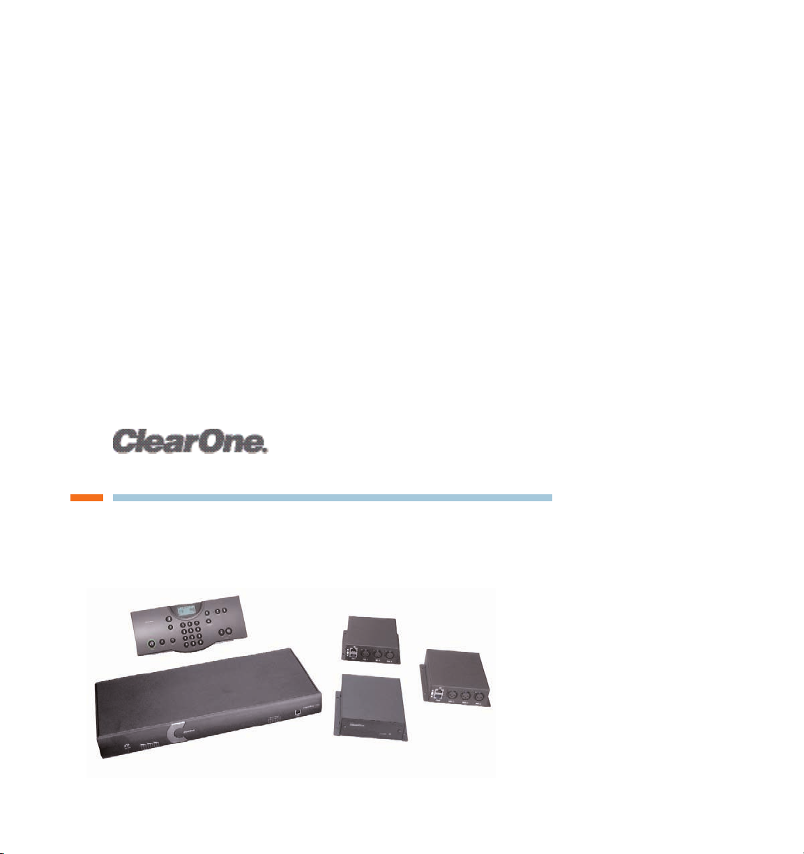
Converge 560/590
USER’S MANUAL
Page 2

ii Technical Services: 800.283.5936
TELEPHONE 1.800.283.5936
1.801.974.3760
FAX 1.801.977.0087
EMAIL tech.support@clearone.com
TECHNICAL SUPPORT
MAX WIRELESS INSTALLATION AND OPERATION MANUAL
CLEARONE PART NO. 800-153-560 NOVEMBER 2005 (REV. 1.0)
© 2005 ClearOne Communications, iinc. All rights reserved. No part of this document m
ay be reproduced in any form or by any means without written permission from ClearOne
Communications. Printed in the United States of America. ClearOne reserves specific
privileges. Inforfrmation in this document is subject to change without notice
Page 3

Table of Contents iii
TABLE OF CONTENTS
INTRODUCTION
. . . . . . . . . . . . . . . . . . . . . . . . . . . . . . . . . . . . . . . . . . . . . . . . . . . . . . . . . . . 5
The Converge 560/590 . . . . . . . . . . . . . . . . . . . . . . . . . . . . . . . . . . . . . . . . . . . . . . . . . . . . . . 5
Product Overview . . . . . . . . . . . . . . . . . . . . . . . . . . . . . . . . . . . . . . . . . . . . . . . . . . . . . . . . . . 7
Basic Room Design . . . . . . . . . . . . . . . . . . . . . . . . . . . . . . . . . . . . . . . . . . . . . . . . . . . . . . . 10
Installation Overview. . . . . . . . . . . . . . . . . . . . . . . . . . . . . . . . . . . . . . . . . . . . . . . . . . . . . . . 11
CONNECTING THE CONVERGE . . . . . . . . . . . . . . . . . . . . . . . . . . . . . . . . . . . . . . . . . . . . . 13
Basic connections . . . . . . . . . . . . . . . . . . . . . . . . . . . . . . . . . . . . . . . . . . . . . . . . . . . . . . . . 13
Auxiliary devices . . . . . . . . . . . . . . . . . . . . . . . . . . . . . . . . . . . . . . . . . . . . . . . . . . . . . . . . . . 17
RAV-WARE SOFTWARE CONFIGURATION . . . . . . . . . . . . . . . . . . . . . . . . . . . . . . . . . . . . . 23
Getting started with RAV-Ware . . . . . . . . . . . . . . . . . . . . . . . . . . . . . . . . . . . . . . . . . . . . . . . 23
RAV-Ware overview. . . . . . . . . . . . . . . . . . . . . . . . . . . . . . . . . . . . . . . . . . . . . . . . . . . . . . . . 24
RAV-Ware connections . . . . . . . . . . . . . . . . . . . . . . . . . . . . . . . . . . . . . . . . . . . . . . . . . . . . . 25
RAV-Ware files. . . . . . . . . . . . . . . . . . . . . . . . . . . . . . . . . . . . . . . . . . . . . . . . . . . . . . . . . . . . 26
Network find . . . . . . . . . . . . . . . . . . . . . . . . . . . . . . . . . . . . . . . . . . . . . . . . . . . . . . . . . . . . . 27
Configuring system settings. . . . . . . . . . . . . . . . . . . . . . . . . . . . . . . . . . . . . . . . . . . . . . . . . 28
Customizing Converge components . . . . . . . . . . . . . . . . . . . . . . . . . . . . . . . . . . . . . . . . . . 32
Microphone configurations. . . . . . . . . . . . . . . . . . . . . . . . . . . . . . . . . . . . . . . . . . . . . . . . . . 41
Line input and output . . . . . . . . . . . . . . . . . . . . . . . . . . . . . . . . . . . . . . . . . . . . . . . . . . . . . . 42
Record and playback . . . . . . . . . . . . . . . . . . . . . . . . . . . . . . . . . . . . . . . . . . . . . . . . . . . . . . 44
Camera controls . . . . . . . . . . . . . . . . . . . . . . . . . . . . . . . . . . . . . . . . . . . . . . . . . . . . . . . . . . 46
Dialer and phonebook usage. . . . . . . . . . . . . . . . . . . . . . . . . . . . . . . . . . . . . . . . . . . . . . . . 48
Advanced features . . . . . . . . . . . . . . . . . . . . . . . . . . . . . . . . . . . . . . . . . . . . . . . . . . . . . . . . 51
USING THE CONVERGE . . . . . . . . . . . . . . . . . . . . . . . . . . . . . . . . . . . . . . . . . . . . . . . . . . . 55
Using the controller . . . . . . . . . . . . . . . . . . . . . . . . . . . . . . . . . . . . . . . . . . . . . . . . . . . . . . . 55
Programming phone preferences . . . . . . . . . . . . . . . . . . . . . . . . . . . . . . . . . . . . . . . . . . . . 57
Page 4

iv Technical Services: 800.283.5936
TABLE OF CONTENTS (CONTINUED)
WEB INTERFACE
. . . . . . . . . . . . . . . . . . . . . . . . . . . . . . . . . . . . . . . . . . . . . . . . . . . . . . . . . 71
Accessing the web interface . . . . . . . . . . . . . . . . . . . . . . . . . . . . . . . . . . . . . . . . . . . . . . . . 71
Dial . . . . . . . . . . . . . . . . . . . . . . . . . . . . . . . . . . . . . . . . . . . . . . . . . . . . . . . . . . . . . . . . . . . . 72
Event log. . . . . . . . . . . . . . . . . . . . . . . . . . . . . . . . . . . . . . . . . . . . . . . . . . . . . . . . . . . . . . . . 74
System check . . . . . . . . . . . . . . . . . . . . . . . . . . . . . . . . . . . . . . . . . . . . . . . . . . . . . . . . . . . . 75
APPENDIX. . . . . . . . . . . . . . . . . . . . . . . . . . . . . . . . . . . . . . . . . . . . . . . . . . . . . . . . . . . . . . . 77
Maintenance . . . . . . . . . . . . . . . . . . . . . . . . . . . . . . . . . . . . . . . . . . . . . . . . . . . . . . . . . . . . . 77
Troubleshooting . . . . . . . . . . . . . . . . . . . . . . . . . . . . . . . . . . . . . . . . . . . . . . . . . . . . . . . . . . 77
Camera pinouts . . . . . . . . . . . . . . . . . . . . . . . . . . . . . . . . . . . . . . . . . . . . . . . . . . . . . . . . . . 80
Specifications . . . . . . . . . . . . . . . . . . . . . . . . . . . . . . . . . . . . . . . . . . . . . . . . . . . . . . . . . . . . 81
Serial commands . . . . . . . . . . . . . . . . . . . . . . . . . . . . . . . . . . . . . . . . . . . . . . . . . . . . . . . . . 83
Compliance . . . . . . . . . . . . . . . . . . . . . . . . . . . . . . . . . . . . . . . . . . . . . . . . . . . . . . . . . . . . 136
Index . . . . . . . . . . . . . . . . . . . . . . . . . . . . . . . . . . . . . . . . . . . . . . . . . . . . . . . . . . . . . . . . . . 141
Page 5

Introduction 5
THE CONVERGE 560/590
The Converge product line is the first room audio conferencing solution with the sound
quality and flexibility of a professionally installed system. The Converge includes an audio
conferencing mixer that uses distributed acoustical echo-cancelling technology to provide
the most intelligible full-duplex audio conference experience possible. Features include:
• Audio mixer for high-quality audio performance in all acoustical environments.
• RF (radio frequency) controller or wired controller with call controls including autoanswer, flash duration adjustment, ringer adjustment and phonebook with speed dial
capabilities.
• Internal telephone hybrid with touch-tone dialing capability.
• Microphone breakout box that enables a set of up to three microphones to be
connected to the Converge--these microphones can be table mics, portable mics, or
whatever type of microphone would be most suitable for the situation at hand. The
Converge 560 includes two breakout boxes connected together and the Converge
590 has three breakout boxes connected together.
SERVICE AND SUPPORT
If you need additional information on how to install, set up or operate your Converge
560/590, please contact us. We welcome and encourage your comments so we can
continue to improve our products and serve your needs.
TECHNICAL SUPPORT
Tel: 1-800-283-5936(USA) or 1-801-974-3760
Fax: 1-801-977-0087
E-mail: tech.support@clearone.com
Web: www.clearone.com
SALES AND CUSTOMER SERVICE
Tel: 1-800-945-7730 (USA) or 1-801-975-7200
Fax: 1-800-933-5107 (USA) or 1-801-977-0087
E-mail: sales@clearone.com
PRODUCT RETURNS
All product returns require a return materials authorization (RMA) number. Please contact
ClearOne Technical Support before attempting to return your product. Make sure you
return all the items that shipped with your product and include a brief description of how
the product was being used when the problem occurred.
INTRODUCTION
Page 6
6 Technical Services: 800.283.5936
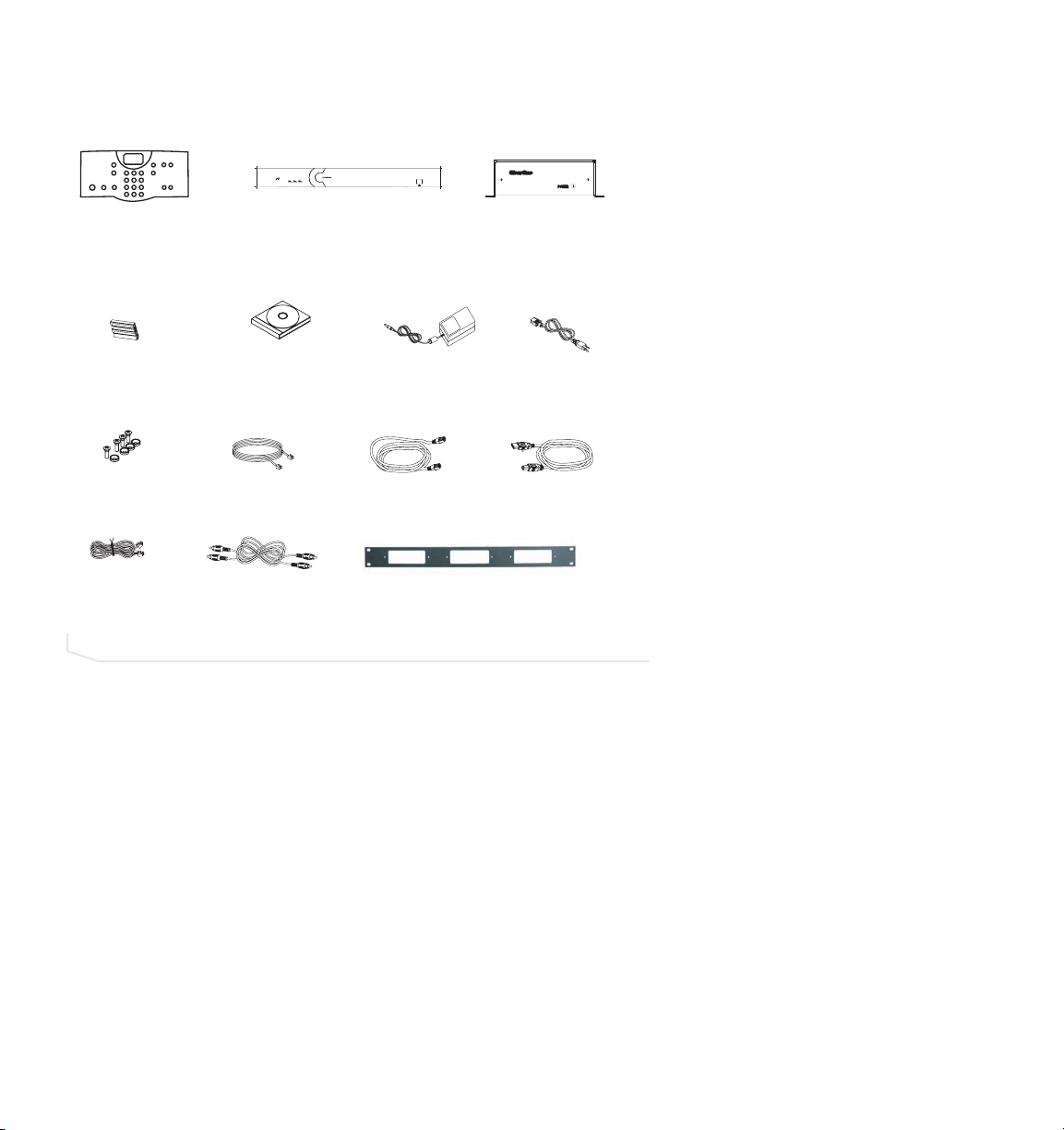
UNPACKING
Carefully remove all components of the Converge system from the packaging. Ensure that
you received the following items:
>
Note
: Rack mount ears are attached to the Mixer box. Refer to Chapter 2 of this
manual for installation instructions.
If any parts are missing, please call the Technical Support Group at 1-800-283-5936 (USA)
or 1-801-974-3760.
>
Note
: ClearOne is not responsible for product damage incurred during shipment. You
must make claims directly with the carrier. Inspect your shipment carefully for obvious
signs of damage. If the shipment appears damaged, retain the original boxes and
packing material for inspection by the carrier. Contact your carrier immediately.
FIGURE 1.1 Converge unpacking
A
B C
ON / OFF
123123123
Audio Mixer
|
CONVERGE
590
INPUT METERING
-30-10-4 0+4+8 +12
Microphone Breakout Box
(2 for Converge 560 &
3 for Converge 590)
MUTE
CONFERENCE
FLASH REDIAL
ON/OFF
RF Controller
or Wired Controller
AAA Batteries
Qty: 4
(with RF controller)
Screw/Washer Rack Kit
Qty: 8
18” RJ-45 Cable
Qty: 2 for Converge 560
Qty: 3 for Converge 590
RAV-Ware Software
and Documentation CD
12' Telephone Cable
6' RCA Cable
Qty: 2
Power Supply
7 ' RJ-45 Cable
Microphone Breakout Box Rack Mount
6' Power Cord
6' USB Cable
Page 7
Introduction 7
PRODUCT OVERVIEW
The following paragraphs give an overview of the Converge 560/590’s componenets.
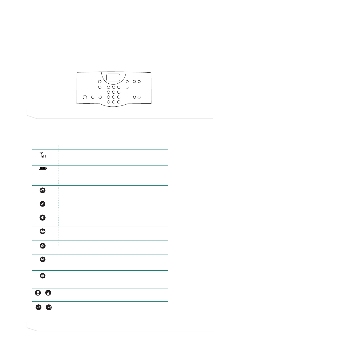
RF (RADIO FREQUENCY) CONTROLLER/WIRED CONTROLLER
The RF controller/wired controller allows you to manage all calls, program user
preferences and adjust settings for your Converge.
KEY FUNCTIONS
FIGURE 1.2 Converge controller
FIGURE 1.3 Converge controller keypad functions
DOWN
UP
MENU
ENTER
PHONEBOOK
CLEAR
DOWN UP
VOLUME
MUTE
123
CONFERENCE
ABC DEF
6
45
GHI JKL MNO
89
7
FLASH REDIAL
ON/OFF
PQRS TUV WXYZ
0
*
HELP
LINE
#
PAUSE
LCD Icon
ANTENNA
SIGNAL
BATTERY
Key
ON/OFF
FLASH
MUTE
STATUS
REDIAL
MENU
ENTER
PHONEBOOK
CLEAR
DOWN UP
VOLUME
Function
Indicates commands are received and acknowledged by base unit and
represents the signal strength from the base unit to the RF controller.
Indicates battery level (RF controller only)
Function
Press to activate the phone and access the dial tone. Press
again to hang up the phone.
Press to use call forwarding, access call waiting, or make a three-way
conference call (if supported by your telephone service).
Press once to mute all microphones during a call.
Press again to unmute.
Press and hold for two seconds to display the status of the Converge.
(RF controller only)
Press once to dial the last number called.
Press once to access the controller programming menu.
Once you are in the Menu, this key serves as the Enter key.
Press once to dial stored numbers.
When you are in the Phonebook, use this key to delete characters or to
go back to the previous screen.
Press down or up to navigate through the menu and phonebook.
Press while on a call to adjust call volume.
Page 8

8 Technical Services: 800.283.5936
MIXER (FRONT)
A.
Telephone LLED
. This indicator lights red when the Converge is powered, but the telco
is on hook (not in use). The indicator lights green when the telco is off hook (in use)
and flashes green during an incoming call.
B.
Microphone sstatus LLEDs
. Nine indicators (Converge 590) or six indicators (Converge
560) indicate the activation status of the mic elements. When a mic element is gated,
the corresponding LED lights green. When mics are muted, the LEDs for the corresponding mics turn red.
C.
Meter LLEDs.
These LEDs represents audio from all inputs.
D.
USB pport
. This port enables USB connection to a PC.
MIXER (BACK)
A.
Telephone SSet, LLine
. RJ-11 connection to an analog telephone jack and an analog
telephone set.
B.
RF aantenna cconnector ((RF ccontroller)
. Connect the external RF antenna to this port.
C.
RS-2232
. RS-232 control port for connection to a control system such as AMX or
Crestron or to a computer.
D.
Camera CControl
. VISCA camera control port. This connection enables microphone
activation to trigger camera presets (voice tracking).
E.
LAN
. This is a 10/100 BaseT auto-detecting Ethernet port for system control through a
data network.
F.
Mic PPod IIn
. Use a Cat. 5 cable with RJ-45 connectors to connect the microphone
breakout boxes.
G.
Playback IIn/Record OOut
. RCA connection to record/playback devices such as a VCR.
H.
Line IIn/Out
. RCA connection to a codec, amplifier or sound card.
I.
Speaker OOutput
. Use speaker wire to connect these push terminals to the speakers.
J.
Power 112 VVDC.
Power supply.
FIGURE 1.4 Converge mixer (front)
FIGURE 1.5 Converge mixer (back)
ANTENNA
Page 9

Introduction 9
MICROPHONE BREAKOUT BOX
A.
Power IIndicator.
Indicates whether the breakout box is powered on or not--a green
light indicates ON.
B.
Microphone CConnectors
. You can connect up to three mics--the mics can be tabletop
mics, button mics, portable mics, etc.
C.
Link CConnectors.
Connect the link line to the IN connector using RJ-45 cable. Connect
the breakout box to the mixer using RJ-45 cable and connect the breakout box’s OUT
connector to the mixer’s IN connector.
FIGURE 1.6 Converge breakout box
A
FRONT VIEW
C
IN
MIC 1 MIC 2 MIC 3
OUT
B
REAR VIEW
Page 10

10 Technical Services: 800.283.5936
BASIC ROOM DESIGN
To ensure best microphone and loudspeaker placement (ceiling- or wall-mount), please
use the manufacturer’s guidelines for the microphones and loudspeakers you choose to
use with your Converge system. For more information on Room Design, or to view the
Converge online training course, visit www.clearone.com.
MICROPHONES
Mic pick-up range depends on room conditions. Background noise, reflective hard
surfaces and the number of participants may affect the pick-up range. Take all of these
factors into account when determining the best placement of the microphones in your
Converge system and then adjust for your specific room conditions.
CEILING-MOUNT LOUDSPEAKERS
For best performance, ceiling loudspeakers should be installed as recommended by the
manufacturer, depending on the kind of microphone being used. For example, if you are
using ClearOne delta mics, then it is recommended that the ceiling loudspeakers be
installed directly above the microphones. For example, if you have a Converge 590 with
three ClearOne delta mics, you would install the ceiling loudspeakers above the first and
third mics.
WALL-MOUNT LOUDSPEAKERS
For best performance, place the left channel loudspeaker on the left side of the room and
the right channel loudspeaker on the right and make sure the back of each loudspeaker is
parallel to the front wall. (Refer to the manufacturer’s specifications and instructions for
ideal loudspeaker placement.)
FOR BEST RF CONTROLLER PERFORMANCE
• Do not install the Converge mixer in a metal cabinet unless you are using the remote
antenna accessory. Part number 910-153-050.
• Keep the mixer within line of sight of the RF controller, such as on the top of a
credenza.
• Ensure antenna is connected to the back of the mixer and is pointed up.
• If installing the mixer in an equipment rack, make sure it is placed at or near the top of
the rack.
FOR BEST AUDIO PERFORMANCE
• Use the provided cables.
• Do not move microphones while on a call.
• Speak at a normal conversation level and direct your voice toward the microphones.
• Do not place microphones next to fans, projectors or computers.
Page 11

Introduction 11
INSTALLATION OVERVIEW
Carefully consider the following items in order to ensure yourself of a smooth installation
process.
READ THE USER MANUAL
Please read through this manual to familiarize yourself with the Converge system. Refer to
the Help file in RAV-Ware for information on the software. Read through all requirements
and safety information to be sure you set up and configure your Converge correctly.
MAKE SURE YOUR NETWORK IS READY
Review all system requirements. Then check with your network administrator to be sure
your network meets all the Converge requirements.
CONNECT CABLES
Connect cables. If you are planning on using the Converge for web or videoconferencing,
you’ll need to connect peripheral equipment. See Chapter 2, Connecting the Converge.
INSTALL SOFTWARE
Install RAV-Ware and then use to adjust sound levels and to configure settings for
additional equipment such as a video codec or a recording device. See Chapter 3, RAVWare Software Configuration.
BEGIN USING
Use the controller to answer and make calls. See Chapter 4, Using the Converge.
SYSTEM REQUIREMENTS FOR RAV-WARE
>
Note
: Using a USB-to-serial adapter is not recommended.
Operating System and RAM
Windows 2000 256 MB RAM
Windows XP 256 MB RAM
Processor 300 MHz Pentium III or better
Monitor 1024 x 768 SVGA (16 bit) high color
Video Card SVGA 1024 x 768 minimum
Free Hard Disk Space 20 MB minimum
RS-232 COM port Up to 115,200 baud rate
USB port USB 1.1–2.0
Flash Support Macromedia Flash Player 7.0
Component
Requirement
Page 12

12 Technical Services: 800.283.5936
NETWORK INFORMATION
To use Converge over a local area network (LAN), you need to know if the LAN uses
Dynamic Host Configuration Protocol (DHCP) or if you need a static IP address.
If the LAN uses DHCP, there is no need to make any network adjustments. If the LAN does
not use DHCP, gather the following information prior to LAN setup:
• The IP address to be assigned to the Converge.
• The subnet mask.
• The IP address of the default gateway.
• The network name to be assigned to Converge.
Page 13
Connecting the Converge 13
BASIC CONNECTIONS
Connecting the Converge should be a smooth process. Once basic connections for audio
conferencing are made, the system is ready to use.
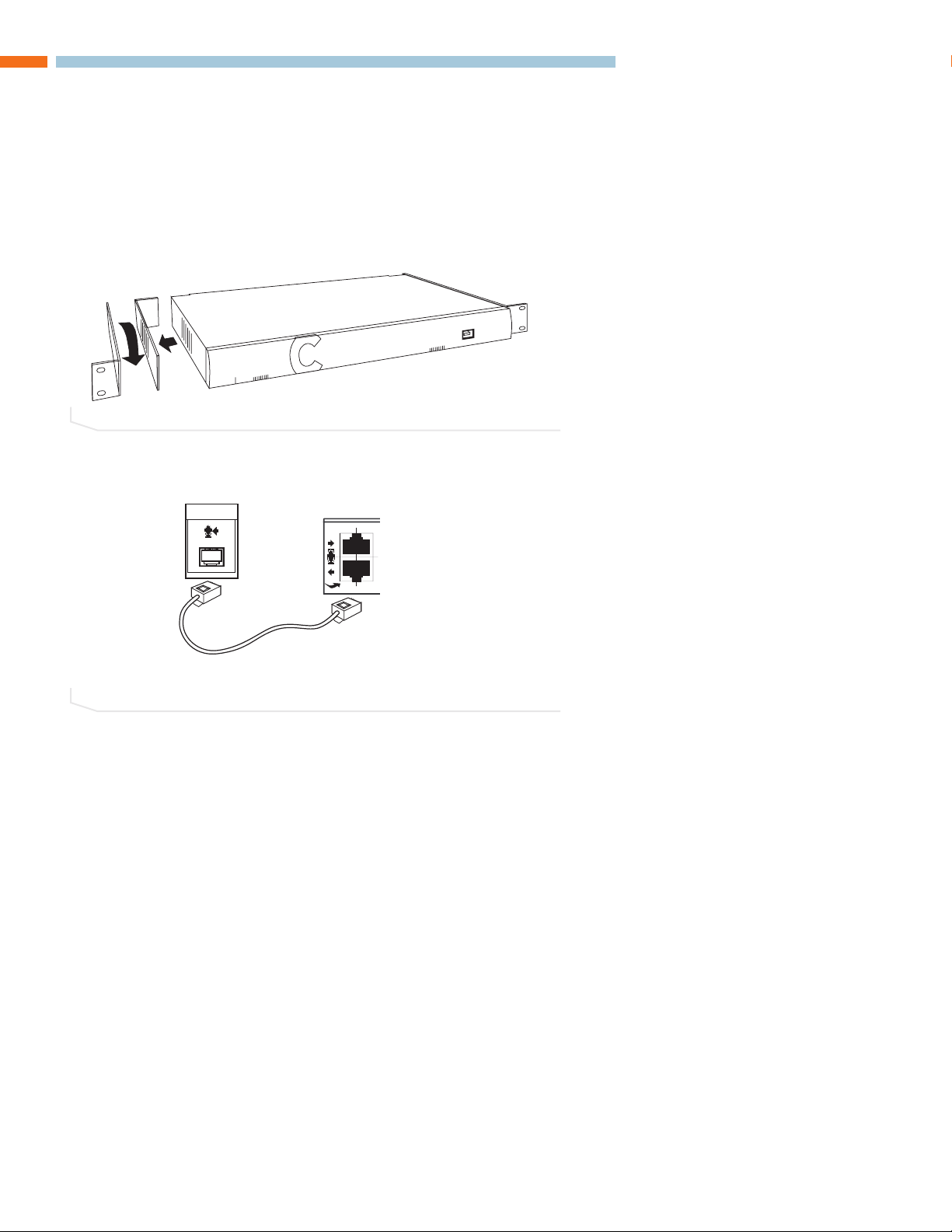
SETTING UP AUDIO CONFERENCING
1. If you are installing the mixer into a rack, remove the side panels, rotate them and
then reattach.
2. Connect the first microphone breakout box to the mixer with the 18” Cat. 5 cable.
CONNECTING THE CONVERGE
RECORD / PLAYBACK
LRIN
L +
L -
R +
R -
SPEAKER
IN
OUT
LINE
12VDC 2.5A
+
-
!
FIGURE 2.1 Attach rack ears
FIGURE 2.2 Connect to first microphone breakout box
Mixer
MIC POD IN
Breakout Box
IN
OUT
MIC 1 MIC 2 MIC 3
18”/45.72cm
Page 14
14 Technical Services: 800.283.5936
3. Connect the second and third microphone breakout boxes using the 18” Cat. 5
cables. (Third breakout box on the Converge 590 only).
4. Connect the microphones to the breakout boxes, as desired.
5. Connect the speakers to the mixer.
>
Note
: For best performance, speakers must be installed properly. Refer to the
manufacturer’s instructions included with your loudspeakers.
RECORD / PLAYBACK
LRIN
L +
L -
R +
R -
SPEAKER
IN
OUT
LINE
12VDC 2.5A
+
-
!
IN
C
FIGURE 2.3 Connect additional microphone breakout boxes
FIGURE 2.4 Connect microphones
L +
L -
R +
R -
SPEAKER
FIGURE 2.5 Connect speakers
IN
Mixer
MIC POD IN
IN
OUT
Breakout Box #2
MIC 1 MIC 2 MIC 3
MIC 1 MIC 2 MIC 3
OUT
OUT
Breakout Box #3
Breakout Box #1
60’
IN
MIC 1 MIC 2 MIC 3
OUT
Breakout Box #3
(Microphones C1-C3)
MIC 1 MIC 2 MIC 3
Breakout Box #1
(Microphones A1-A3)
IN
MIC 1 MIC 2 MIC 3
OUT
Breakout Box #2
(Microphones B1-B3)
MIC 1 MI
Page 15
Connecting the Converge 15
6. Using the RJ-11 cable, connect an analog telephone jack to the
Line
jack on the
mixer.
>
Note
: For instructions on connecting to a digital phone line, refer to page 20.
7. Using an RJ-11 cable (not supplied), connect an analog telephone set to the
Set
jack
on the mixer (optional).
8. Using the 7' Cat. 5 cable, connect the mixer to the network. (Network settings can be
changed in RAV-Ware.)
CAMERA
CONTROL
LAN
RS-232
SET
LINE
FIGURE 2.6 Connect telephone cable
CAMERA
CONTROL
RS-232
SET
n
et
FIGURE 2.7 Connection to analog handset
MIC POD IN
RECORD / PLAYBACK
L
R
L
R
IN
OUT
IN
OUT
FIGURE 2.8 Connection to network
TELEPHONE
TELEPHONE
Connection o
analog hands
LAN
Page 16
16 Technical Services: 800.283.5936
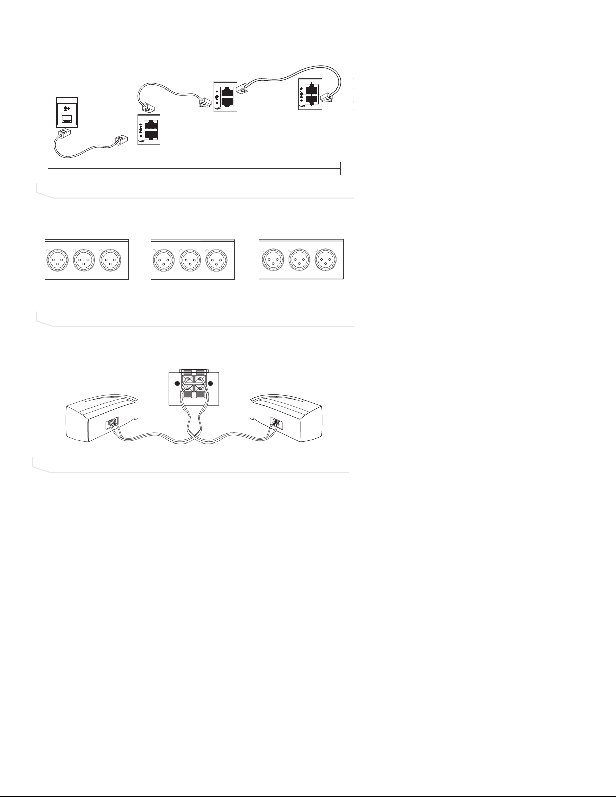
9. Using the power supply cords, connect the mixer to an electrical outlet.
10. If using the wired controller, connect the controller to the mixer’s RS-232 serial port
using the supplied RJ-11 to DB-9 adapter (see figure 2.10). If using the RF controller,
attach the external antenna and turn it until it is upright (see figure 2.11).
+
-
!
FIGURE 2.9 Connection to electrical outlet
TELEPHONE
LINE
RS-232
SET
FIGURE 2.11 Attach external antenna for RF controller
FIGURE 2.10 Attach wired controller to mixer
12VDC 2.5A
RECORD / PLAYBACK
LINE
L +
TELEPHONE
LRIN
CAMERA
LAN
RS-232
CONTROL
SETLINE
L
MIC POD IN
OUT
IN
OUT
R
R +
-
+
!
12VDC 2.5A
L -
R -
SPEAKER
40’/12.2m
&190
72
MUTE
/'07
'06'4
CONFERENCE
2*10'$11-
#$% &'(
%.'#4
)*+ ,-. /01
FLASH REDIAL
&190 72
2345 678 9:;<
ON/OFF
81.7/'
2#75'
*'.2
.+0'
Page 17
Connecting the Converge 17
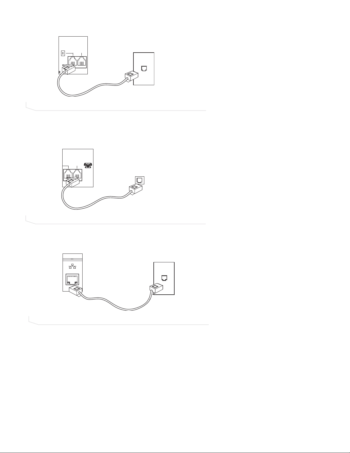
11. If using the RF controller, insert four AAA batteries into the battery compartment in the
bottom of the unit.
AUXILIARY DEVICES
The mixer allows connection to a number of different audio and video peripherals, such as
video codecs, VCRs, cameras and computers.
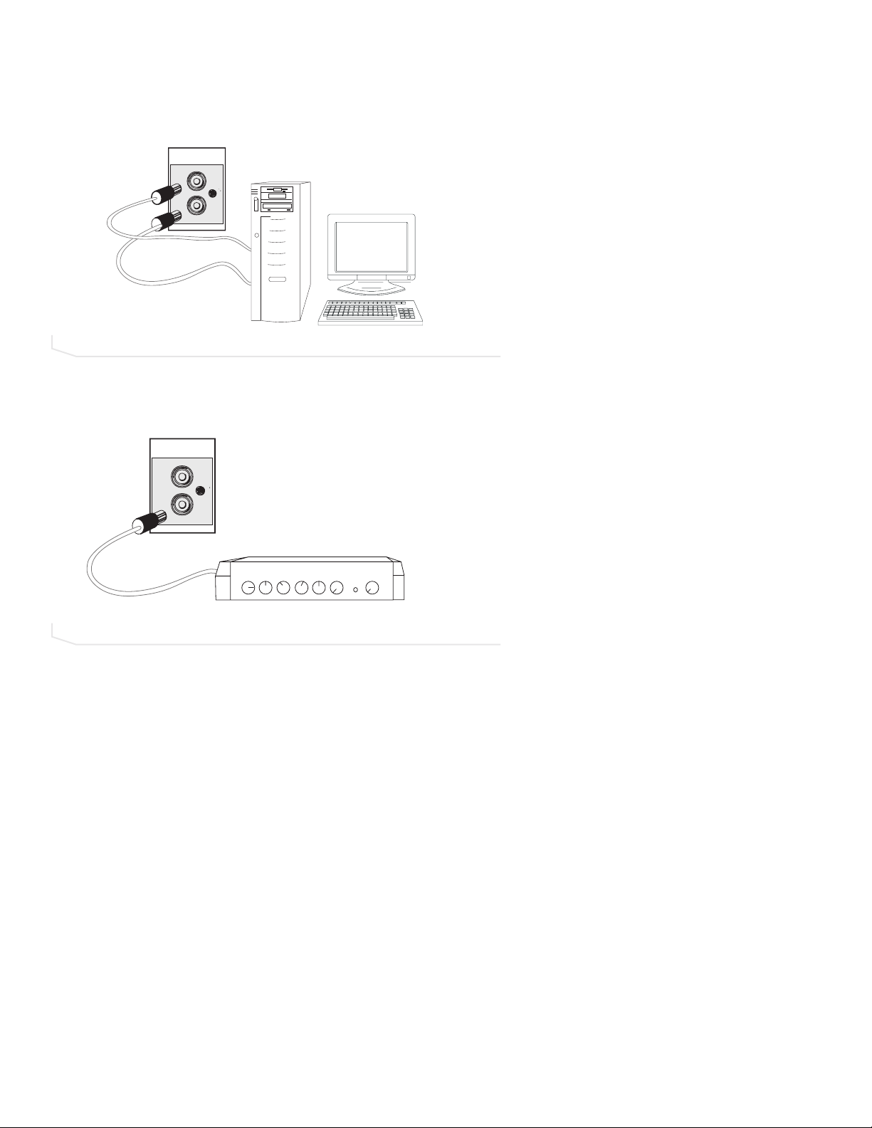
CONNECTING VIDEO CODECS, AMPLIFIERS, AND SOUND CARDS
Line input/output devices such as video codecs, amplifiers and sound cards can be connected to the Line In or Line Out connectors on the Converge mixer. These connectors
provide mono-audio.
To connect a video codec
1. Using an RCA cable, connect the
Line IIn
on the Converge mixer to the line out on a
video codec.
2. Using an RCA cable, connect the
Line OOut
on the Converge mixer to the line in on a
video codec.
Back of Controller
FIGURE 2.12 Insert batteries
FIGURE 2.13 Connecting a Line In/Out device
Batteries
LINE
IN
OUT
Page 18
18 Technical Services: 800.283.5936
To connect a sound card
1. Using an RCA cable, connect the
Line IIn
on the Converge mixer to the line out on a
sound card.
2. Using an RCA cable, connect the
Line OOut
on the Converge mixer to the line in on a
sound card.
To connect to an amplifier
1. Using an RCA cable, connect the
Line OOut
or
Record OOut
on the Converge mixer to
the line in on an amplifier.
>
Note
: Use RAV-Ware to adjust the equalization and volume of these devices. Refer to
pages 39–46 for more information. When using RAV-Ware, be sure to drag the amplifier to the correct device (either line out or record). This will properly assign the AEC
reference and change the volume command on the controller to control the external
amplifier volume.
LINE
FIGURE 2.14 Connecting a sound card
FIGURE 2.15 Connecting an amplifier
IN
OUT
LINE
IN
R
OUT
Page 19
Connecting the Converge 19
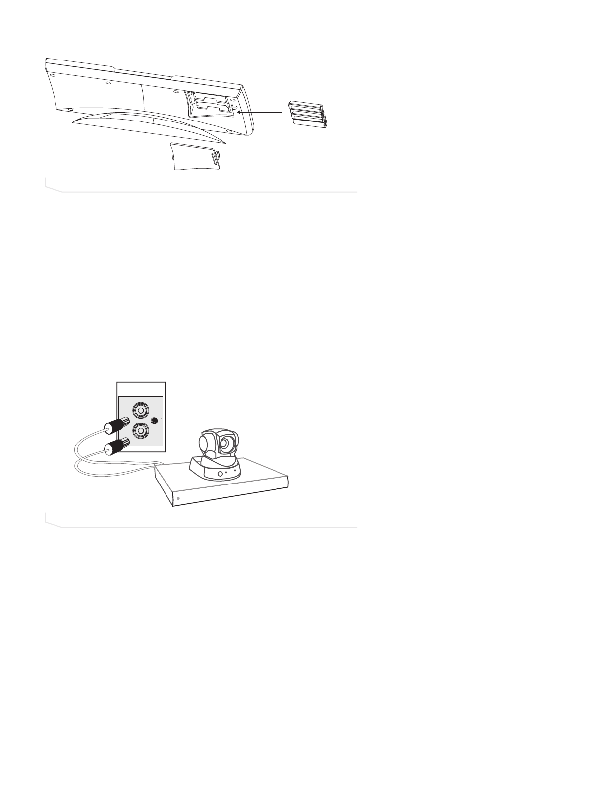
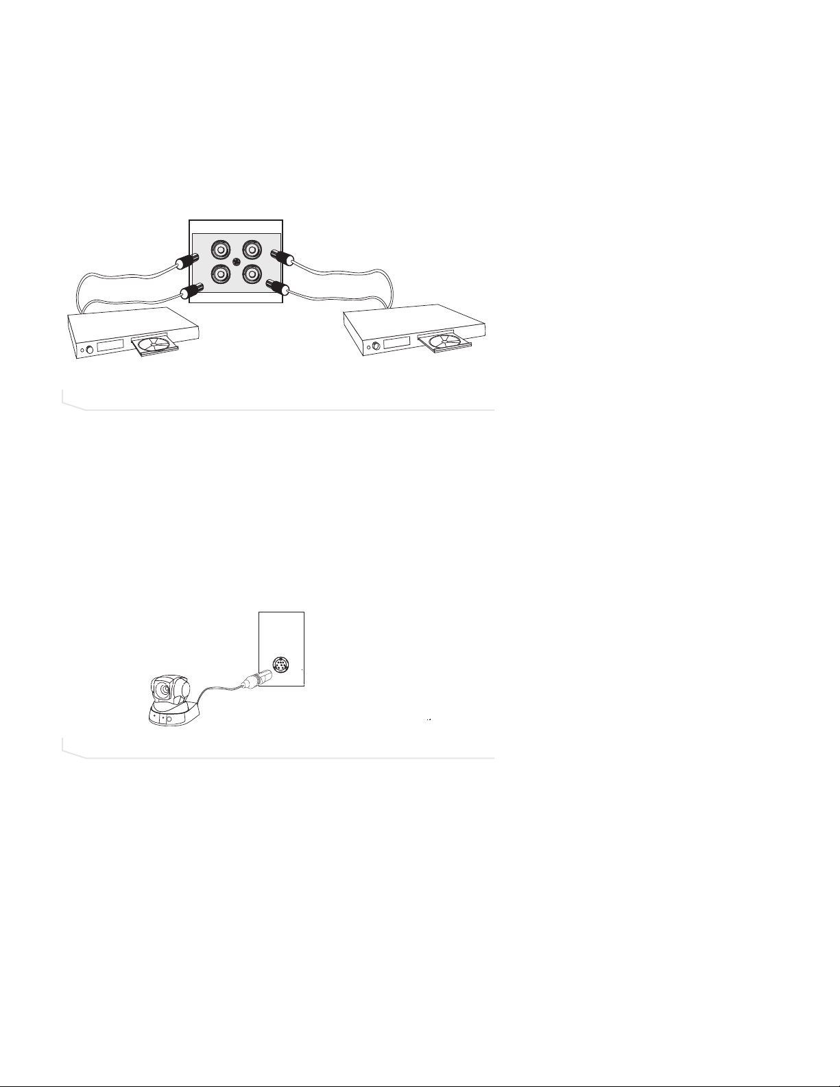
CONNECTING VCRS AND DVD PLAYERS
You can record your audio/video conference or play audio using a playback device such
as a VCR or DVD player.
To connect to record/playback
1. For recording, connect the
Left
and
Right Audio Out
on the Converge to the left and
right audio in on the VCR or DVD player.
2. For playback, connect the
Left
and
Right Audio In
on the Converge to the left and
right audio out on the VCR or DVD player.
>
Note
: You can also connect a mono-signal device or a non-record/playback device to
these line in/out connectors.
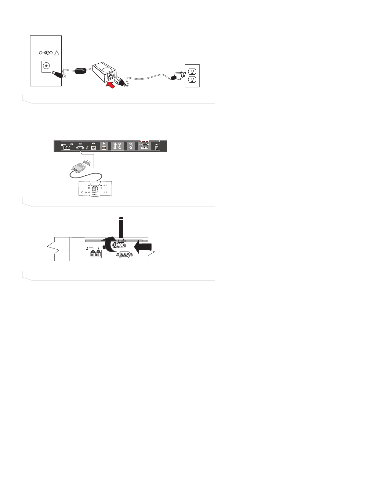
CONNECTING PTZ CAMERAS
The Converge system provides voice-tracking capabilities through VISCA control port connection to a Pan, Tilt, Zoom camera. Voice Tracking allows the camera to move to preset
positions based on microphone activation. For instructions on programming the presets,
see page 47.
To add a camera
1. Connect the camera to the
Camera CControl
port on the mixer.
>
Note
: The camera video out signal connects to a video codec.
PLAYBACK / RECORD
FIGURE 2.16 Connecting a record/playback device
FIGURE 2.17 Connecting a camera
L
IN
R
L
OUT
R
CAMERA
CONTROL
Page 20
20 Technical Services: 800.283.5936
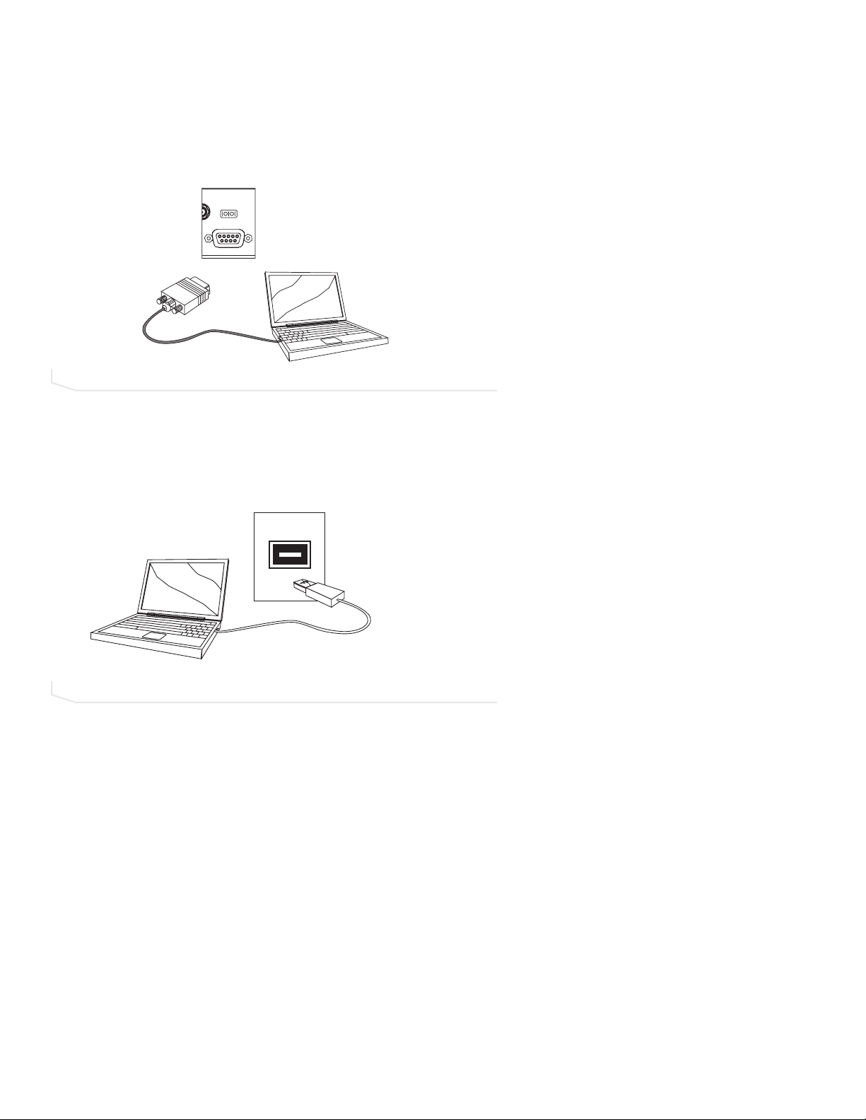
CONNECTING FOR SERIAL CONTROL
You can connect a computer or a control device, such as an AMX or Crestron, to the
Converge mixer through the serial control port. See page 83 for a list of the serial
commands.
To connect to a computer through the serial port
1. Connect computer to
Control
port on the back of the mixer using a 9-pin straight-
through serial cable.
CONNECTING FOR USB CONTROL
You can also connect a computer to the Converge through the USB port.
To connect to a computer through the USB port
1. Connect computer to the USB port on the front of the mixer using a USB cable.
MIC POD IN
CAMERA
CONTROL
LAN
RS-232
FIGURE 2.18 Connecting a computer serially
FIGURE 2.19 Connecting a computer through the USB
Page 21
Connecting the Converge 21
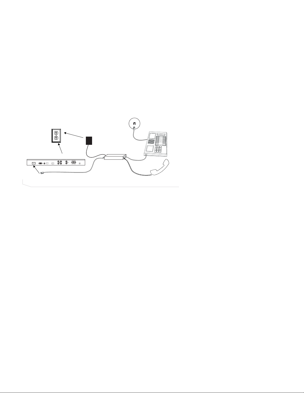
DIGITAL PHONES
If you have a digital (PBX) telephone service, you need to run an analog extension from
the PBX (recommended for best performance) or use a digital-to-analog telephone line
converter. For more information, contact ClearOne Technical Support.
>
Note
: If you connect the Converge through a digital-to-analog line converter, you will
not be able to use the tabletop controller or the RAV-Ware dialing interface to make
calls. You will instead need to dial from the digital phone. The phone handset must be
kept off hook for the duration of the call.
To connect to a digital phone
1. Connect one end of the telephone cable into the
Line
jack on the back of the mixer
and the other end into the digital-to-analog converter.
2. Connect the converter’s power adapter into an electrical outlet.
3. Connect a second telephone cable from the converter to a PBX phone. Consult the
converter’s user manual for more information.
FIGURE 2.20 Connecting the Converge mixer to a digital-to-analog converter
Telco Line
Electrical
Outlet
AC Adapter
Control
Lan
Camera
Converge mixer
Record/Aux
Left +
Left In
Mic Pod
Right In
Right +
Left Out
Right Out
Power
12V DC 1A
Left -
Right -
Phone Jack
Digital-to-Analog
Converter
Digital, PBX,
or Multi-line phone
Page 22

22 Technical Services: 800.283.5936
Page 23
RAV-Ware Software Configuration 23
GETTING STARTED WITH RAV-WARE
Please ensure that you have administrative privileges before attempting to install
RAV-Ware™on computers running Windows 2000 or later. You should also review the
System Requirements on page 9 to ensure software will run correctly and that you have all
the necessary network information.
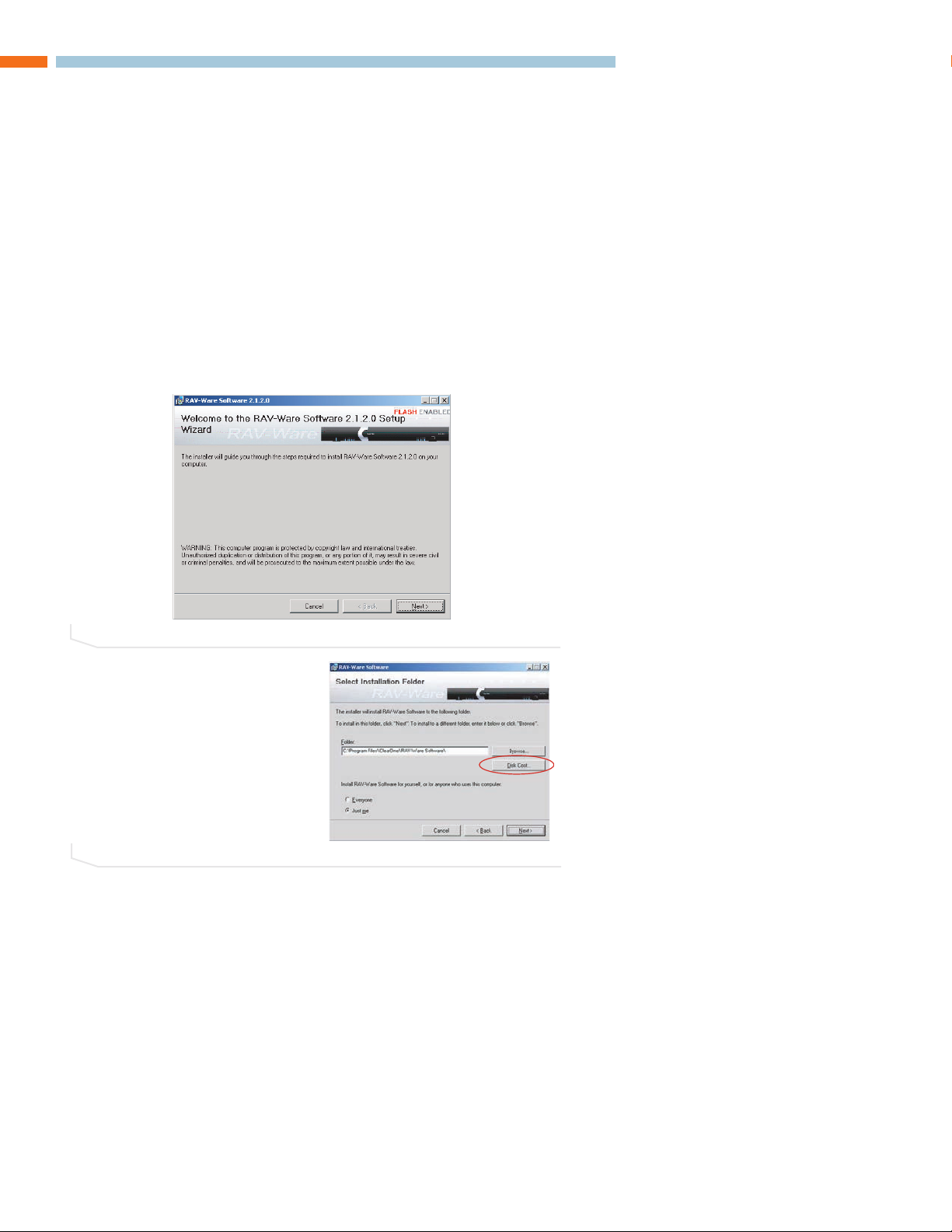
INSTALL RAV-WARE
1. Close all programs or applications running on your PC or laptop and insert the RAVWare CD into the CD-ROM drive.
• If the Autorun feature is enabled on the PC, the CD will open automatically.
• If the Autorun window does not open, select Run from the Start menu.Type
<drive>:\\rav.exe where <drive> is the letter of the CD-ROM drive (e.g.,
D:\\rav.exe).
2. Follow the on-screen instructions.
>
Note
: The Disk Cost button allows you
to view all available disk space.
RAV-WARE SOFTWARE CONFIGURATION
FIGURE 3.1 Installing RAV-Ware
FIGURE 3.2 Disk Cost
Page 24
24 Technical Services: 800.283.5936
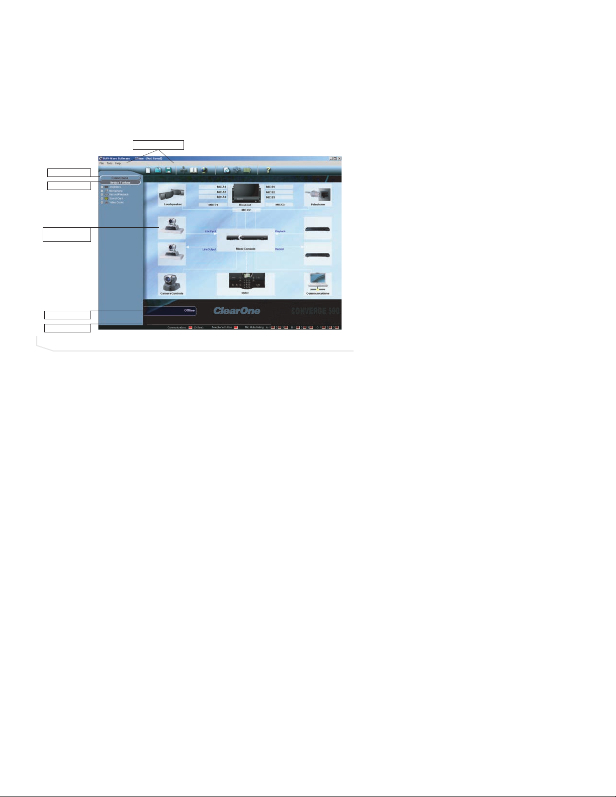
RAV-WARE OVERVIEW
ClearOne’s RAV-Ware software provides an easy interface for configuring system settings
and customizing the audio in your Converge 590/560 conferencing system. While the
Converge system is designed to work out of the box for audio conferencing, RAV-Ware is
required to adjust audio levels and equalizer settings for the Converge components as
well as the auxiliary audio devices. Once installed, RAV-Ware allows configuration locally
through USB or RS-232 connection, or remotely through the Ethernet connection.
Menus aand TToolbar
: Easily create, open or save files, find Converge systems on the
network, add phonebook entries, configure regional settings, and view the event log.
Connections
: Lists available units connected through serial or USB ports, or on the net-
work.
Device TToolbox
: Lists common brands of auxiliary audio products (video codecs, sound
cards, microphones, VCRs, and amplifiers). The audio settings for these devices have
been optimized for use with the Converge system.
Configuration SScreen
: Quickly access the configuration windows for the Converge system
by clicking the icons.
Online/Offline IIndicator:
Shows connection status of RAV-Ware (online/offline) and the
name of the connected unit.
Status IIndicators
: Status for Communications (green = online, red = offline), Telephone In
Use (red = not in use, green = in use), and Mic Mute/Gating (red = mute/green = gated
on).
Menus and Toolbar
FIGURE 3.3 Converge 590 shown
Connections
Device Toolbox
Con guration
Screen
Online/Of ine
Status Indicators
Page 25
RAV-Ware Software Configuration 25
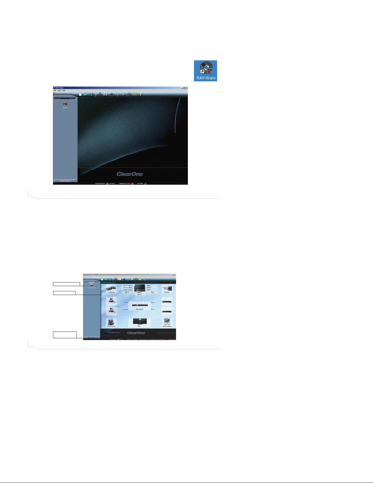
RAV-WARE CONNECTIONS
When you connect to the Converge unit, RAV-Ware automatically finds all Converge units
connected serially, by USB, or on the same subnetwork and lists them in the Connections
pane.
TO CONNECT TO THE CONVERGE
1. Double-click the RAV-Ware desktop icon or select RAV-Ware from the
Start menu (Start/Programs/RAV-Ware/RAV-Ware.exe).
2. Click the Converge icon you want to configure in the Connections pane.
• If you are connected serially or by USB, the Converge configuration window
appears.
• If you are connected through the network, you will be prompted to enter a user
name and password. The default user name is
ClearOne
and the default password
is
RAV
(user name and password are not case sensitive).
>
Note:
To connect to a Converge unit on another subnetwork, use Network Find (see
page 27).
FIGURE 3.4 RAV-Ware units
FIGURE 3.5 RAV-Ware units
Connected Converge unit
Con guration Screen
Online indicator with
Converge unit name
Page 26
26 Technical Services: 800.283.5936
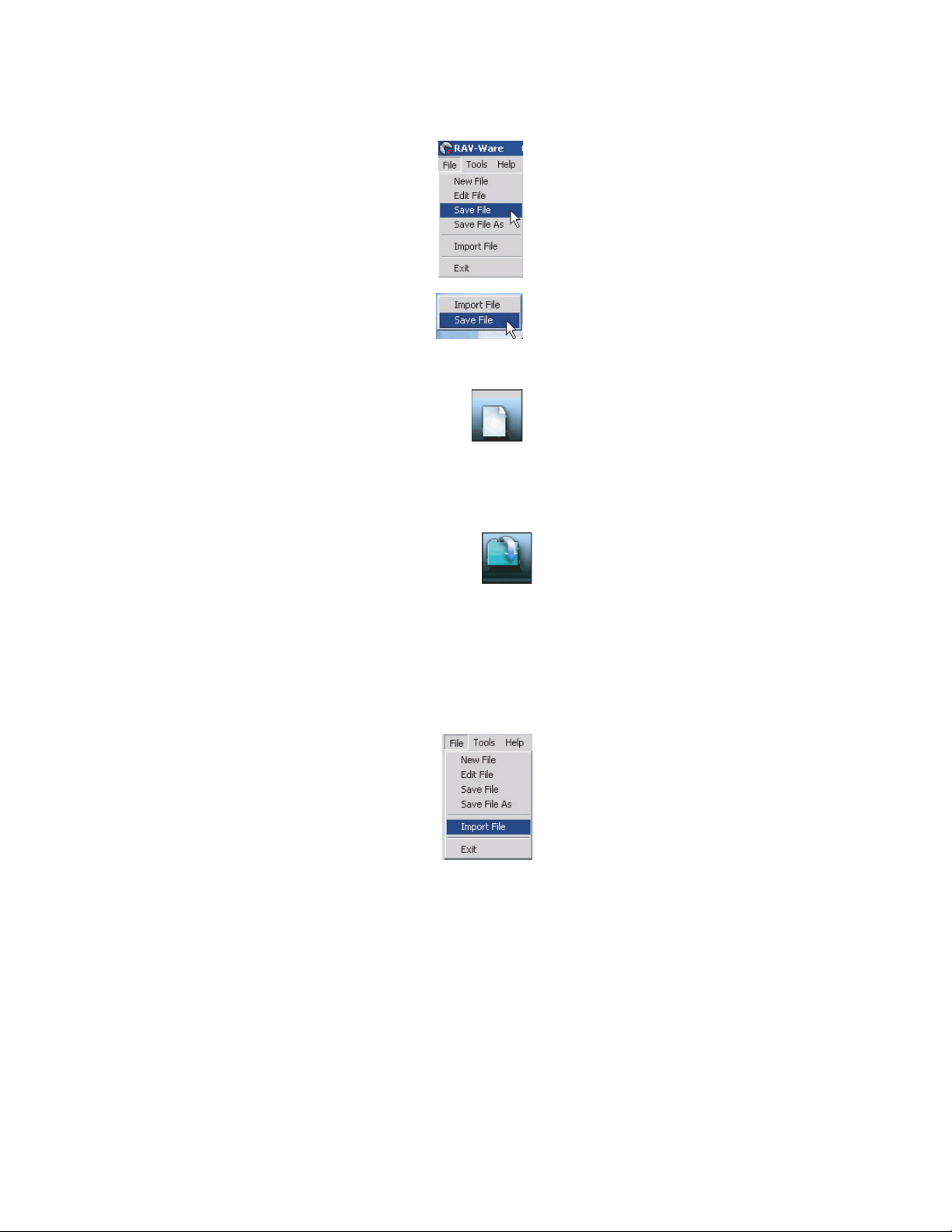
RAV-WARE FILES
You can save current RAV-Ware files, create new files, edit existing files, and import files
using the menus and toolbar icons. When connected to a Converge unit, any changes
made to a RAV-Ware file are updated immediately within the Converge unit. The file must
be saved to remain permanent within the RAV-Ware file.
TO SAVE A FILE
1. From the File menu, select
Save FFile
or click the
Save FFile
icon
on the toolbar.
2. Browse to the desired location and enter the name of the file.
3. Click
Save
.
>
Tip:
You can right-click on the configuration window and select
Save FFile
to save your file. You can also select
Save FFile AAs
to
rename and save the file you are working on.
TO CREATE A NEW FILE
1. Click the
New FFile
toolbar icon or select
New FFile
from the File menu.
2. Select either the Converge 560 or Converge 590 depending on your
system.This will open the Configuration Screen where you can set
user preferences for your Converge system.
3. Click
Save
.
TO EDIT AN EXISTING FILE
1. Click the
Edit FFile
toolbar button or select
Edit FFile
from the File menu.
2. Locate and select the file you want to edit.
3. Click
Open
.
4. Make the desired changes to the file.
5. Click
Save
.
>
Note:
The changes only take effect after they have been imported to a connected
Converge system.
TO EDIT AN EXISTING FILE
1. Connect to a Converge unit.
2. From the File menu, select
Import
.
3. Choose your Converge file.
4. Click
Open
. The Converge unit reboots and updates with all the
file changes.
>
Tip:
You can also right-click on the configuration window and
select
Import
to import a saved Converge file.
Page 27
RAV-Ware Software Configuration 27
NETWORK FIND
Network Find allows you to connect to any Converge system on another subnetwork or
network using its IP address or a unique network name. Use Network Find to access
Converge units not listed in the Connections pane, but which reside on a different subnetwork or network.
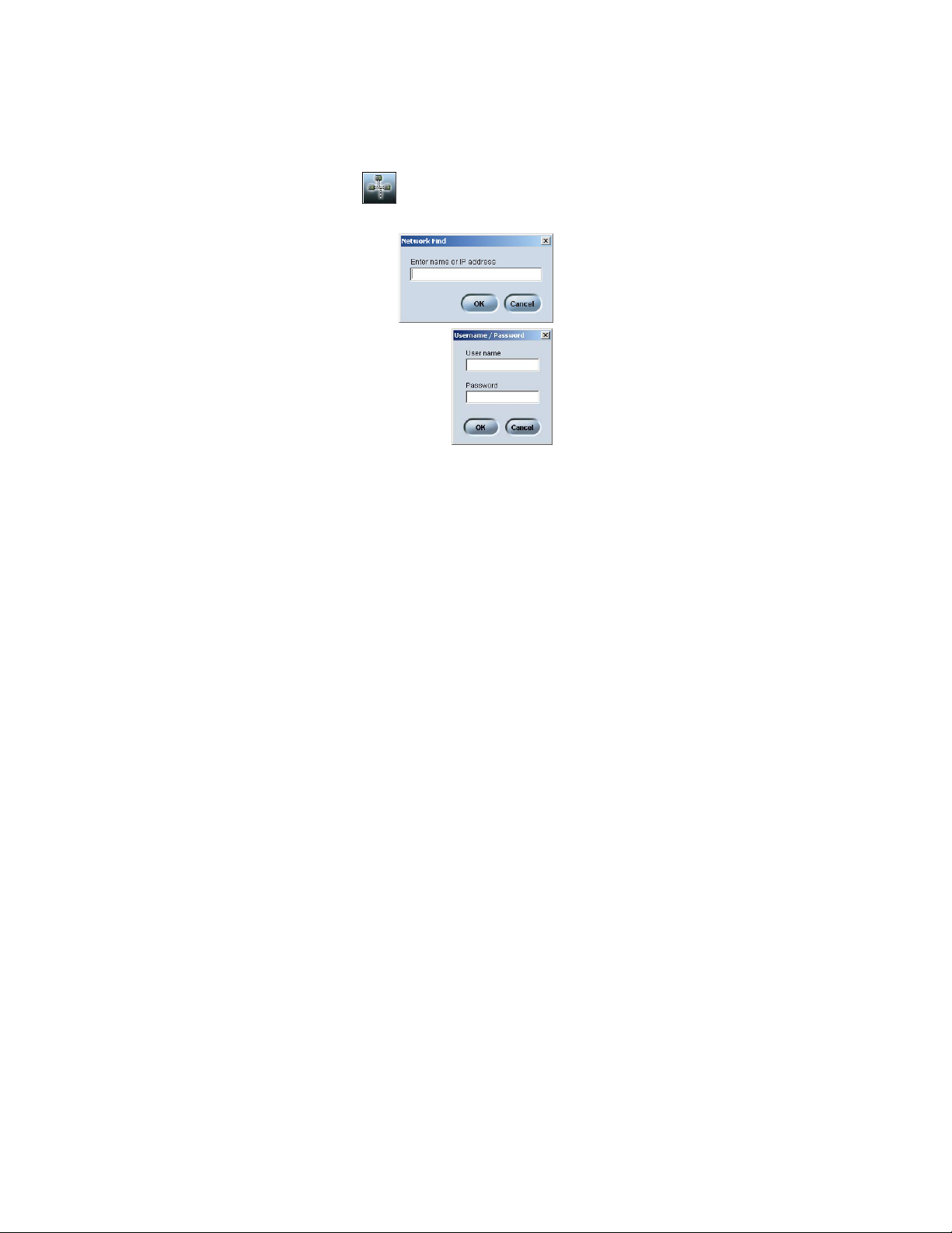
TO OPEN THE NETWORK FIND
1. Click the
Network FFind
icon on the toolbar.
TO CONNECT TO A SYSTEM ON THE NETWORK
1. Enter the
IP aaddress
or
name
of the Converge system
to which you want to connect.
2. Click OK.
3. You will see a password prompt window. Enter the
User nname
and
Password
of the networked system. The default user name
is
ClearOne
and the default password is
RAV.
4. Click OK. The system icon will appear in the Connection list and
the Configuration screen will open.
>
Note:
Once you have connected to a Converge unit using
Network Find, a shortcut connection icon for that unit will display
as long as RAV-Ware can find the unit on the network. If
RAV-Ware cannot find the unit, the shortcut icon will be removed.
Page 28
28 Technical Services: 800.283.5936
CONFIGURING SYSTEM SETTINGS
System settings include Communication, Regional, and Telephone settings.
COMMUNICATION SETTINGS
The Communication Settings window allows you to adjust the connectivity settings of
external devices that communicate with the Converge, including the network and serial
connections. You can connect a PTZ camera to the Camera port and use the Voice
Tracking feature. You can also change the RF frequency (RF controller only) to match the
frequency of your controller or if you are experiencing interference on the current channel.
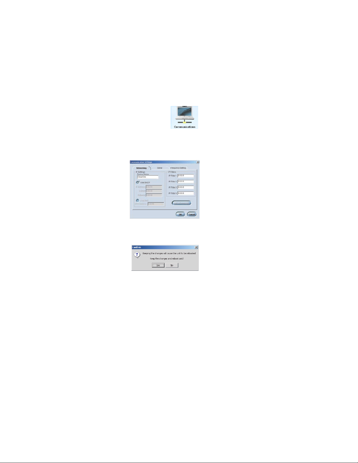
To open Communication Settings
1. Click the
Communications
icon in the Configuration screen.
>
Note:
When Converge is connected to a DHCP network, the
network, IP, gateway and subnetwork addresses are automatically
assigned. Unless you want to specify a static IP address, there is
no need to configure network settings.
To create a static IP address
>
Note
: Contact the network administrator for
network settings.
1. In the Networking tab, create a unique network name and enter it in the
Device Name
field. (Default is ClearOne-XX where XX is the
last two digits of the MAC address.)
2. Clear the
Use DDHCP
option and enter the IP,
Subnet
and
Gateway
addresses.
3. Select
Use DDNS
if you have a Domain Name
Server and want name resolution (to use a
network name) for your static IP address.
4. In the IP Filters section, enter specific IP
addresses that will be allowed to access the
Converge system. You can specify a range of
IP addresses by using zeros. For example,
entering 192.168.105.0 will allow any IP
addresses in the 192.168.105.1 to
192.168.105.254 range to access the
Converge system.
5. Click
OK.
6. Click
Yes
to save your settings.
Page 29
RAV-Ware Software Configuration 29
To change the User Name and Password
1. In the Networking tab, click
User/Password.
2. Specify the
User NName
.
3. Type the
Password
.
4. Retype the password to confirm.
5. Click OKto save changes and close the window.
>
Note
: This option is only available when you are connected to a Converge unit. User Name and Password
are not case sensitive and can be between 1 and 12
characters.
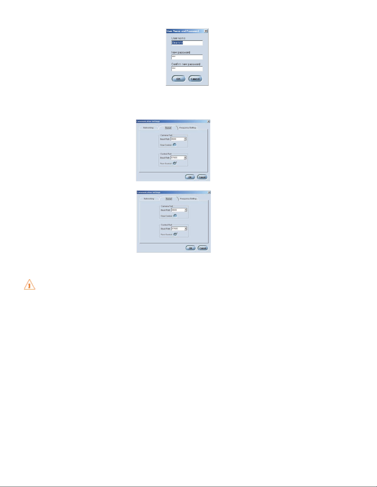
To configure the Camera port
1. In the Serial tab, set the
Baud RRate
to
match the baud rate indicated in the
camera specifications.
2. Select
Flow CControl
to enable hardware flow
control.
3. Click OKto save settings and close the
window.
To configure the Control port
1. Set the Control Port
Baud RRate
to match the
baud rate of the PC COM port or the control
device.
2. Select
Flow CControl
to enable hardware flow
control. (Flow Control is selected as default
in wireless units.)
3. Click OKto save settings and close the
window.
>
Note
: Flow control is the regulation of information between two devices that are
connected to one another.
Attention
: If you are connected to the Converge unit through the serial port, you will
need to reboot the unit before the baud rate and flow control changes take place. If
you are connected to the Converge unit through the USB port or Ethernet, changes
are made instantly.
Page 30
30 Technical Services: 800.283.5936
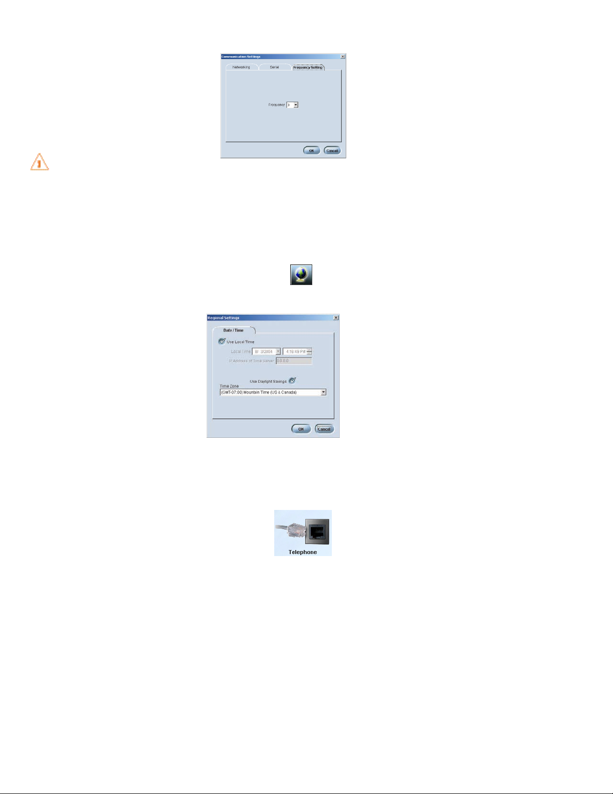
To change RF frequency channel (RF Controller only)
1. In the Frequency tab, select a frequency.
2. Click OKto save settings and close the
window.
>
Note
: The channel frequency allows the mixer
to communicate with the controller. The
frequency used by RAV-Ware must match the
frequency used by the controller. See page 62
to set the controller frequency.
Attention
: If you are using the European or
South African version of Converge, Frequency
1 and Frequency 8 are the same frequency.
REGIONAL SETTINGS
In the Regional Settings window, you can configure the date and time to ensure an accurate time stamp on log files.
To open Regional Settings
1. Click the
Regional SSettings
icon in the Configuration screen or
select
Regional SSettings
from the Tools menu.
To set date and time
1. Select
Use LLocal TTime
if you want to use
the time on your local computer. Or clear
the
Use LLocal TTime
checkbox and enter
the IP address for the time server.
2. Select
Use DDaylight SSavings
if your region
observes daylight savings time.
3. Select your
Time ZZone
and click OK.
4. Click
Yes
to confirm changes.
TELEPHONE SETTINGS
In the Telephone Settings window you can set telephone preferences such as auto-answer,
auto-disconnect, ringer melody and program the local number. You can also adjust the
telco level control, country setting and the flash settings.
To open Telephone Settings
1. Click the
Telephone SSettings
icon in the Configuration screen.
Page 31

RAV-Ware Software Configuration 31
To change telephone preferences
1. In the Preferences tab, set the system to
Auto-AAnswer
after
2 RRings
or
4 RRings
or
select
Disabled
if you want to manually
answer calls.
2. Select
Auto-DDisconnect
if you would like
Converge to disconnect when it detects
loop-drop or call progress tones.
3. Select from three available ringer
melodies. Click
Ringer TTest
to hear
selected melody.
>
Note
: This option is only available when you are connected to a Converge unit.
4. Select
Audible CConnect
if you would like one tone to sound when the Converge is
taken off hook and two tones to sound when the Converge is on hook.
5. Adjust ringer volume using the
Ringer Level
slider
.
6. Enter the
Local NNumber
for the Converge system. The local number displays on the
third line of the Controller LCD.
To select telephone configuration
1. In the Configuration tab, select the
Country
where the phone is being used.
2. Select the flash duration from the Flash
Setting list. This setting is dependent on the
requirements of your PBX or telephone
provider.
Warning
: The country code must be set
correctly in RAV-Ware and the RF Controller
to ensure that the unit operates properly and
that it complies with the country’s telco
requirements. Changing this code to a country other than the intended country of
operation might cause the Converge to be non-compliant.
To adjust telephone level
1. Select
Receive AALC
. Clearone recommends
keeping Receive ALC (automatic level control)
selected. This feature adjusts the far-end audio
to keep it at a constant level.
2. Use the sliders to adjust the level of the telco
transmit and telco receive.
>
Note
: If you select ALC, the Telco Receive
slider is disabled.
3. Click OKto save settings and close the
window.
Page 32

32 Technical Services: 800.283.5936
CUSTOMIZING CONVERGE COMPONENTS
Your Converge system is pre-configured for optimal audio quality right out of the box.
However, you can customize the audio and adjust the volume to match user preferences.
You can also change the mix of audio being sent to the far-end conference site and
recording devices.
MICROPHONE BREAKOUT BOXES
The Converge 590 has three breakout boxes representing three sets of three microphones
each; the Converge 560 has two breakout boxes representing two sets of three
microphones each. Control for all of the microphones is done through the breakout box
tabs: Level, Processing, and Gating. You can enable/disable automatic level control (ALC)
settings, enable/disable mute, enable/disable phantom power, enable/disable acoustic
echo cancellation, enable/disable noise cancellation,
enable/disable speech lift, adjust speech lift level,
control gating mode, set gate ratio, hold time, and
attenuation, set the decay rate if the gate is lost, and
set chairman override.
To access Microphone Settings
1. Click the
Breakout
icon on the Configuration screen. The breakout box settings screen
appears with the Level tab selected.
FIGURE 3.6 Microphone settings: level tab (Converge 560 shown)
Page 33

RAV-Ware Software Configuration 33
BREAKOUT BOX LEVEL TAB
From this tab (see figure 3.6), you can view the make and model of the mic that has been
dragged and dropped from the device toolbox onto the specific microphone connection of
the breakout box. You can determine if a mic is gated on or muted by the Gating indicator
being green or red, respectively. You can set the coarse gain and fine gain for the microphone channel, and read the post gain meter. You can also enable/disable automatic level
control (ALC) settings, enable/disable mute, and enable/disable phantom power.
To adjust Coarse Gain
The Coarse Gain sets the analog gain for the microphone channel.
1. Using the slider, adjust the coarse gain for the microphone channel. The meter will
display levels, when enabled. Enable the meter by clicking the check box.
To adjust Fine Gain
The Fine Gain sets the fine gain for the microphone channel. The Fine Gain allows you to set
the gain limits more precisely than with the coarse gain control.
1. Using the slider, adjust the fine gain for the microphone channel. The meter will
display levels, when enabled. Enable the meter by clicking the check box.
To enable ALC
ALC automatically adjusts microphone levels to ensure participants’ voices are
transmitted at consistent levels regardless of whether people are speaking loudly or softly.
1. Click the
ALC
button. The indicator will turn green when ALC is enabled.
To enable Mute
1. Click the
Mute
button. The Mute indicator will turn red and the Gate indicator next to
“Connected to:” will also turn red when Mute is enabled.
To enable Phantom Power
Phantom power is an auxiliary power source to power certain types of microphones. The
phantom voltage is 24VDC.
1. Click the
Phantom PPower
button. The indicator will turn green when Phantom Power is
enabled.
BREAKOUT BOX PROCESSING TAB
Click on the
Processing
tab from the Microphone Settings screen to access microphone
processing features. You can enable/disable acoustic echo cancellation (AEC), set the
NLP (non-linear processing level), enable/disable noise cancellation, adjust the
cancellation depth, enable/disable speech lift, adjust speech level, and set the filter from
this tab (see figure 3.7).
Page 34

34 Technical Services: 800.283.5936
To disable Acoustic Echo Cancellation (AEC)
AEC prevents echo from reaching the far-end site. AEC should be kept enabled for normal
operation.
1. Click
AEC
to disable Acoustic Echo Cancellation; the LED turns off. The default set-
ting is with AEC enabled; the LED is green when AEC is enabled.
To set the Non-linear Processing (NLP) level
Non-linear Processing is an intelligent suppressor that removes any residual echo that
remains after acoustic echo canecllation.
1. Click radio button correponding with the desired level. You can set the NLP level to
aggressive, medium, soft, or off.
To disable Noise Cancellation (NC)
Noise Cancellation enhances speech clarity by attenuating the amount of background
noise in the signal. ClearOne recommends keeping NC enabled.
1. Click NCto disable noise cancellation; the LED turns off. The default setting with NC
enabled; the LED is green when NC is enabled.
To set the Noise Cancellation Depth
Adjust cancellation depth to the setting which provides the best combination of low noise
and maximum speech clarity.
1. Using the slider, set the noise cancellation depth to the desired level.
FIGURE 3.7 Microphone settings: processing tab (Converge 560 shown)
Page 35

RAV-Ware Software Configuration 35
To enable Speech Lift
Speech lift enables the microphone channel to be reinforced to the loudspeaker output
channel.
1. Click the
Speech LLift
button. The indicator will turn green when speech lift is enabled.
To adjust Speech level
Speech level sets the attenuation level for the amplifier output of the selected
microphone.
1. Using the slider, adjust the speech lift level to the desired setting between -18dB and
0dB.
To set Filter
The Filter button allows you to set up to three PEQ filters for the microphone channel.
1. Click the
Filter
button. A pop-up window (see figure 3.8) appears for the selected
microphone channel. The filter is displayed in Filter Graph view.
FIGURE 3.8 Microphone filter (filter graph view)
Page 36

36 Technical Services: 800.283.5936
2. To begin, click
Add FFilter
to add a filter to the graph. Modify the filter settings as
desired. The settings are described below:
•
Active FFilter
selects among filters on the graph.
>
Note
: No filters exist until you click
Add FFilter
to add filters to the graph.
•
Type
selects the filters type. The only type available for the Converge 560/590 is
parametric EQ (PEQ).
•
Frequency
selects the center frequency (in Hertz) for the filter you are configuring.
Range is from 20Hz to 15kHz. Default is 1000Hz.
•
Gain
adjusts the gain value from -15 to 15dB, in 1 dB steps. Default is 0dB.
• Q, or Quality factor, selects the ratio of the center frequency divided by the bandwidth. Q reflects an inverse relationship to the bandwidth, and adjusts from .2 to
28.8. The default is 4.4.
•
Bandwidth
establishes the numerical difference between the upper and lower
points of a filter's audio passband. Range is from .05 to 5 octaves. The default is
.33.
• The
Bypass
box, when selected, bypasses the selected filter.
•
Phase
generates—on the graph—the phase relationship of the graphed frequency
response.
•
Bypass AAll
bypasses all filters.
•
Add FFilter
adds a filter to the graph or table, centered at 1kHz and 0dB.
•
Remove FFilter
removes the selected filter from the graph or table.
• The
Table VView
button toggles between the Filter Graph and Filter Table views. The
Filter Table view displays the active filter, filter type, center frequency, gain, Q, and
bandwidth parameters of the graph window, but in a table format. You can configure filters from this view as well as the graph view. Click
Table VView
again to return
to the Filter Graph view.
3. When you finish configuring filters, click
Close
to exit.
Page 37

RAV-Ware Software Configuration 37
BREAKOUT BOX GATING TAB
Click on the
Gating
tab from the Microphone Settings screen to access microphone gating
features. You can control the gating mode, set the gate ratio, hold time, and attenuation,
set the decay rate, and control chairman override from this tab (see figure 3.9).
To set Gate Mode
Set Gate Mode allows you to set the gate mode. Choices are limited to manual on,
override on, and auto. Manual on activates a mic; the microphone contributes to gating
parameters. Override on activates a mic; the microphone does not contribute to gating
parameters. Auto automatically gates the mic on or off, based on input levels and other
parameters programmed into the Converge 560/590.
1. Click the
Gate MMode
radio button corresponding with the desired setting.
To adjust Gate Ratio
Gate ratio specifies how much louder the mic audio level must be above the ambient
noise level before the mic gates on (see figure 3.10).
1. Using the slider, adjust the gate ratio to the desired level.
FIGURE 3.9 Microphone settings: gating tab (Converge 560 shown)
Page 38

38 Technical Services: 800.283.5936
To set Hold Time
Adjust hold time allows you to set how long the channel stays gated on after the mic gates
off (see figure 3.10).
1. Using the slider, adjust the hold time to the desired level.
To adjust Off Attenuation
Adjust off attenuation allows you to set the amount of level reduction applied to a mic
when it is gated off.
1. Using the slider, adjust the off attenuation of the microphone to the desired level.
To adjust Decay Rate
Set decay rate allows you to set how quickly a mic gates off after the hold time expires.
1. Click the
Decay RRate
radio button for the desired amount of decay after the gate is
lost.
To enable Chairman Override
Chairman override provides gating priority for a mic. When a mic with chairman
override enabled gates on, all mics that don't have chairman override enabled will gate off.
1. Click the
Chairman OOverride
radio button enable the chairman override feature.
FIGURE 3.10 Converge 560/590 automixing gate functions
Page 39

RAV-Ware Software Configuration 39
LOUDSPEAKERS
You can adjust your loudspeaker equalization, change volume levels and enable
ClearEffect in the Loudspeaker window. Equalization in RAV-Ware is similar to the bass
and treble adjustments on a stereo. Increasing or decreasing the low, mid and high
frequencies and levels allows you to customize loudspeaker audio and provide the optimal
listening experience for your users.
To access Loudspeaker settings
1. Click the
Loudspeaker
icon in the configuration screen.
The Loudspeaker settings dialog box appears.
To enable ClearEffect
When ClearEffect is enabled, it causes the
audio coming from the telephone line to
emulate wideband audio. It does this by
adding high and low frequencies to the
audio signal, creating a fuller sound.
1. Click the
ClearEffect OOff/On
button. The
indicator will turn green when
ClearEffect is enabled.
To adjust Equalization
1. Adjust the the Low, Mid and High frequency tones using the Equalization sliders.
To enable Mute
1. Click the
Mute
button. The Mute
indicator will turn red when Mute is
enabled.
To adjust audio level (Volume)
1. Using the slider, adjust the volume. The meter will display output levels.
2. Click
Close
to save the settings.
Page 40

40 Technical Services: 800.283.5936
MIXER CONSOLE
The Mixer Console allows you to create audio mixes for the different outputs, adjust volume levels and view the output meters. The audio inputs are shown along the left side of
the window and the audio outputs are along the top.
To open the Mixer Console
1. Click the
Mixer CConsole
icon in the Configuration
screen. The Mixer Console window appears (see
figure 3.11).
To create a mix of audio
1. Select which audio is to be included in each output mix. A check mark indicates the
audio will be included in the output mix.
To adjust audio levels
You can also adjust levels by opening the configuration windows for each component.
Changes made to the levels on the Mixer Console window will be reflected in the
configuration windows.
1. Use the sliders to adjust the audio levels for Playback, Telephone Rx, Line In,
Loudspeaker, Line Output, Telco Tx, Record Out, and the microphones.
FIGURE 3.11 Mixer Console (Converge 560 shown)
Page 41

RAV-Ware Software Configuration 41
EFFECTS OF USING AN EXTERNAL AMPLIFIER
If you connect an external amplifier to the Converge unit on either the Line Out jack or the
Record Out jack, the mixer console options change.
• If you place an external amplifier on the Line Output, the options to route any audio
to the loudspeakers and to route the microphones to the Line Output are no longer
available.
• If you place an external amplifier on Record, the options to route any audio to the
loudspeakers and to route the microphones to the Record output are no longer
available.
See page 18 for information on connecting an amplifier.
MICROPHONE CONFIGURATIONS
The Converge breakout box icon has connections for three sets of microphones, A1-A3,
B1-B3, and C1-C3 (Converge 590 only). You can configure these microphones through
RAV-Ware. You can use microphones that have preconfigured settings from the Device
Toolbox or you can manually set up the microphones using the Add Device feature of the
Device Toolbox (see page 54).
PRECONFIGURED MICROPHONES
The settings for many common microphones have been pre-configured for optimal
performance with the Converge system. Preconfigured devices are listed in the Device
Toolbox and can be dragged and dropped onto any of the microphone labels.
To select a preconfigured microphone
1. Click the
Device TToolbox
button to display preconfigured
devices.
2. Click the plus sign (+)to expand the microphone category.
3. Click the microphone name and drag it to the Configuration screen. Drop over the
Microphone label. The label will change based on the selected microphone.
Page 42

42 Technical Services: 800.283.5936
LINE INPUT AND OUTPUT
The Converge mixer has jacks for Line Input and Line Output that allow you to connect different auxiliary devices. You can configure audio levels for these devices through RAVWare. You can use devices that have preconfigured audio settings from the Device
Toolbox or you can manually set the audio settings for your line in and line out devices.
PRECONFIGURED VIDEO CODECS, AMPLIFIERS, AND SOUND CARDS
The audio settings for many common auxiliary devices such as video codecs, VCRs,
amplifiers and sound cards, have been pre-configured for optimal performance with the
Converge system. Preconfigured devices are listed in the Device Toolbox and can be
placed on the Line In and Line Out icons.
>
Note
: If you would like to add a device to the Device Toolbox, please refer to the
Device Toolbox Editor on page 54.
To select a preconfigured line-level device
1. Click the
Device TToolbox
button to display preconfigured
devices (see figure 3.12).
2. Click the plus sign (+)to expand the category that matches your device type.
3. Click the device name and drag it to the Configuration screen. Drop over the Line
input or Line Output icon. The label and icon will change based on the selected
device.
>
Note
: Video codecs will cover both Line Input and Output. A sound card should be
placed on Line Input, Line Output, or on both Input and Output for web conferencing.
An amplifier is Output only.
FIGURE 3.12 Line input device list (Converge 560 shown)
Page 43

RAV-Ware Software Configuration 43
ADJUSTING LINE INPUT/OUTPUT SETTINGS
If your device is not listed in the Device Toolbox you can manually customize and configure the audio of your auxiliary devices in the Line Input and Line Output windows. Line
input and output devices include video codecs, CD players, amplifiers and sound cards.
To access Line Input Settings
1. Open the Line Input window by clicking on the
Line IInput
device icon. The Line Input dialog box
appears.
To adjust Line Input Equalization
1. Adjust the the Low, Mid and High frequency
tones using the Equalization sliders.
To enable Line Input Mute
1. Click the
Mute
button. The Mute
indicator will turn red when Mute is enabled.
To adjust Line Input Audio Level (Volume)
1. Using the slider, adjust the volume. The meter
will display output levels.
>
Note
: To save the name and setting of your line input device, refer to the Device
Toolbox Editor on page 54.
To access Line Output settings
1. Open the Line Output window by clicking on the
Line OOutput
device icon.The Line Output dialog box
appears.
To adjust Line Output Equalization
1. Adjust the the Low, Mid and High frequency
tones using the Equalization sliders.
To enable Line Output Mute
1. Click the
Mute
button. The Mute
indicator will turn red when Mute is enabled.
Page 44

44 Technical Services: 800.283.5936
To adjust Line Output Audio Level (Volume)
1. Using the slider, adjust the volume. The meter will display output levels.
>
Note
: To save the name and setting of your line output device, refer to the Device
Toolbox Editor on page 54.
RECORD AND PLAYBACK
Record and Playback devices include VCRs, DVD players and sound cards. However, the
Playback/Record jacks are line level inputs and outputs and are not restricted to these
devices. You can use devices that have preconfigured audio settings from the Device
Toolbox or you can manually set the audio settings for your VCRs or DVD players.
PRECONFIGURED RECORD/PLAYBACK DEVICES
The audio settings for many common record/playback devices have been preconfigured
for optimal performance with the Converge system. Preconfigured devices are listed in the
Device Toolbox and can be placed on the Record and Playback icons.
To select a preconfigured record/playback device
1. Click the
Device TToolbox
button to display preconfigured
devices.
2. Expand the record/playback category to see a list of record/playback devices (see
figure 3.13).
FIGURE 3.13 Record/playback device list (Converge 560 shown)
Page 45

RAV-Ware Software Configuration 45
3. Click the device name and drag it to the Configuration
screen. Drop over the Record or Playback icon. The
label and icon will change based on the selected
device.
>
Note
: You are not limited to record and playback
devices with these connectors. The Record and
Playback jacks are line input and line output jacks and
can be connected to video codecs, CD players and
amplifiers.
To remove a device
1. Right-click on the device you want to remove.
2. Select
Clear DDevice
.
ADJUSTING RECORD/PLAYBACK SETTINGS
If your device is not listed in the Device Toolbox you can manually customize and configure the audio of your auxiliary devices. The Record settings window is used to customize
and configure audio being sent to recording devices that are connected to the record jack
on the RAV mixer. The Playback settings window is used to customize and configure the
audio from the playback device that is connected to the Playback jack on the Converge
mixer.
To open Playback Settings
1. Open the Playback configuration window by clicking
on the
Playback
device icon. The Playback window
appears.
To adjust Playback Equalization
1. Adjust the the Low, Mid and High frequency
tones using the Equalization sliders.
To enable Playback Stereo Mix
While the Converge provides mono-only audio, it
will accept left and right audio from a stereo
device. However, you must select Stereo Mix to
ensure proper level adjustments are made.
1. Select
Stereo MMix
if your playback device
uses stereo inputs (default in on).
To enable Playback Mute
1. Click the
Mute
button. The Mute
indicator will turn red when Mute is enabled.
Page 46

46 Technical Services: 800.283.5936
To adjust Playback Audio Level (Volume)
1. Using the slider, adjust the volume. The meter will display output levels.
>
Note
: To save the name and setting of your playback device, refer to the Device
Toolbox Editor on page 54.
To open Recording Settings
1. Open the Record configuration window by clicking
on the
Record
device icon. The Record window
appears.
To adjust Recording Equalization
1. Adjust the the Low, Mid and High frequency
tones using the Equalization sliders.
To enable Recording Mute
1. Click the
Mute
button. The Mute indicator will
turn red when Mute is enabled.
To adjust Recording Audio Level (Volume)
1. Using the slider, adjust the volume. The meter
will display output levels.
>
Note
: To save the name and setting of your
recording device, refer to the Device Toolbox
Editor on page 54.
CAMERA CONTROLS
The Converge system provides voice tracking capabilities through a VISCA control port
connection to a PTZ camera.
SETTING CAMERA PRESETS
The camera presets are programmed in RAV-Ware and assigned to each microphone pod.
When a specific microphone is activated, the PTZ camera will move to the associated preset camera position. The Converge 590 supports nine camera positions and a home position. The Converge 560 supports six camera positions and a home position.
>
Note
: The PTZ camera can still be controlled manually from the camera or video
codec remote control.
To open Camera Controls
1. Click the
Camera CControls
icon in the Configuration screen.
Page 47

RAV-Ware Software Configuration 47
To set camera presets
1. Select the
Camera CControl MMode
,
either Sony or Canon.
2. Select which camera you are programming from the
Camera
list.
3. Select the
Camera DDelay
. Camera
delay is the amount of time the
microphone must be activated before
the camera moves to the preset
position and amount of time the
microphone must be inactive before
returning to the home position.
ClearOne recommends setting the
camera delay to at least two seconds
to prevent the camera from changing
positions at every sound.
4. Using the directional arrow buttons and the
Zoom IIn
and
Out
buttons, position the
camera for the first microphone.
5. Click
Save PPreset
under the microphone to assign the camera position to the mic.
6. Repeat steps 1-5 for the remaining camera positions.
7. Select
Voice TTracking SSystem EEnabled
.
>
Note
: Once you set the presets, do not switch Camera Control Mode (the camera
type). This will delete all presets.
8. Click
Close
to save the settings.
To test camera presets
1. Deselect
Voice TTracking SSystem EEnabled
.
2. Select the camera you are testing.
3. Click
Run PPreset
for each mic to test the programming. The camera moves to the
preset position for each microphone.
4. Select
Voice TTracking SSystem EEnabled
.
(Converge 560 shown)
Page 48

48 Technical Services: 800.283.5936
DIALER AND PHONEBOOK USAGE
The Converge system includes a Phonebook that stores up to 20 names and phone
numbers. Phonebook entries may be entered through RAV-Ware or using the Controller.
The Dialer in RAV-Ware mimics the Controller and can be used to make calls, mute
microphones, and adjust the loudspeaker volume. See chapter 4, Using the Converge, for
information on using the Controller.
PHONEBOOK
RAV-Ware features a Phonebook utility which stores up to 20 phone numbers. These
numbers are also assigned a speed dial number for dialing convenience through the
Controller. Phonebook entries are listed in alphabetical order. You can add, edit or delete
entries from the Phonebook window.
To open the Phonebook
1. Click the
Phonebook EEdit
button on the toolbar or select
Phonebook
Edit
from the Tools menu.
To add a Phonebook entry
1. Click
New EEntry
.
2. Enter the
Name
and
Number
.
3. Enter a
Speed DDial NNumber
.
4. Click
Add EEntry
.
To delete a Phonebook entry
1. Select the entry you want to remove.
2. Click
Remove
.
To edit a Phonebook entry
1. Select the entry you want to edit.
2. Make the desired changes to the entry.
3. Click
Change
.
Page 49

RAV-Ware Software Configuration 49
DIALER
While most calls will be made using the controller, you can also manage all your calls from
the Dialer in RAV-Ware. You can dial a number, redial the last dialed call and
disconnect calls. You can also use flash settings, mute the microphones and adjust
loudspeaker volume.
To open the Dialer
1. Click the
Phonebook EEdit
button on the
toolbar or select
Phonebook EEdit
from the
Tools menu. The Dialer window appears (see
figure 3.14).
>
Note
: This option is only available when you
are connected to a Converge unit.
To make a call
1. Click the
ON/OFF
button.
2. Dial the number as you would on a standard phone. The number appears at the top
of the display window.
>
Note
: You can also pre-dial the number and press the
ON/OFF
button to connect the
call.
>
Tip
: You can also dial using the 0-9, star (*) and number (#) on your keyboard. Use
the comma (,) key to enter a two second pause. The Enter key connects to and disconnects from the telephone line.
FIGURE 3.14 Dialer window
Page 50

50 Technical Services: 800.283.5936
To make a call from the Phonebook
1. Using the mouse, select the number in the phonebook. The number appears in the
display window.
2. Click the
ON/OFF
button to dial the call.
>
Tip
: You can also double-click the name in the phonebook. The phone will be taken
off hook and the number dialed.
To end a call
1. Click the
ON/OFF
button.
To redial
1. Click the
REDIAL
button. The phone will automatically be taken off hook and the last
dialed number will be called.
To send a Flash signal
1. The Flash key can be used for call transfer, call waiting or conference calling if your
telephone service includes these features. Refer to your local telephone service
provider for details.
To mute/unmute
1. Click the
MUTE
button to mute all microphones. The LED will illuminate red.
2. Click the
MUTE
button again to unmute all microphones. The LED will turn off.
To adjust loudspeaker volume
1. Use the UPand
DOWN
buttons to adjust the loudspeaker volume to the desired level.
To return to the Configuration screen
1. Click the
Switch tto FFlow WWindow
link to return to the
Configuration screen.
Page 51

RAV-Ware Software Configuration 51
ADVANCED FEATURES
RAV-Ware has several advanced features which allow you to perform system checks
and administrative functions.
SYSTEM CHECKS
The System Diagnostics window allows you to check your Converge system to be sure all
components of your system are connected and working properly.
To open System Checks
1. Click the
System CChecks
button or select
System CChecks
from the Tools menu.
>
Note
: This option is only available when you are connected to a Converge unit.
To run System Checks
1. Click the
START
button. If you are
local (in the same room as the
loudspeakers), you will hear a tone
as the Converge checks all components. When the check is complete,
lights will indicate the status of each
component. Green indicates the
component is connected and
functioning. Red indicates a problem
with the component.
(Converge 560 shown)
Page 52

52 Technical Services: 800.283.5936
EVENT LOG
The Event Log keeps record of a user-selectable events. You select which events you want
recorded and RAV-Ware keeps a log, allowing you to periodically review events and make
sure the system is running smoothly. You can also save the Event Log as a .txt file. Check
the Event Log when there are communication errors or for other troubleshooting.
To open the Event Log
1. Click the
Event LLog
toolbar button or select
Event LLog
from the
Tools menu.
To track events
1. Select the events you
would like to log.
To save an Event Log
1. Click the
Save
button.
2. Name the file.
3. Click
Save
. The log is
saved as a .txt file.
To print an Event Log
1. Click the
Print
button.
2. Select the printer.
3. Click
Print
.
FIGURE 3.15 Event logs
Selection
Default
Reboot
Errors
Password
Telco
Dialing
Call Duration
System Check
Battery Life
Function
Logs when the mixer settings are defaulted.
Logs every time the Converge system reboots.
Logs DSP communication errors only.
Logs failed and successful access through TCP/IP or web interface.
Logs when telco was enabled and disabled.
Logs dialed numbers.
Logs how long each call lasts.
Logs when system checks are performed and the results of the checks.
Logs battery level as reported by the RF Controller (wireless units only).
Page 53

RAV-Ware Software Configuration 53
ERROR MESSAGES
When the Converge system encounters an error, an error icon will appear in the
lower left-corner of the screen. Review this log to troubleshoot problems.
To view Error Messages
1. Click the
Error
icon in the
lower-left corner of the
Converge window.
To clear Error Messages
1. Click
Clear
.
>
Note
: DSP communication
errors can be tracked using
the Event Log.
FIRMWARE UPGRADES
Firmware upgrades are included with any updated RAV-Ware release. Once the RAV-Ware
update has been installed, you should upgrade the firmware. Firmware can be upgraded
through the network, serial or USB connection.
To open the Converge Firmware Loader
1. Click the
Firmware LLoader
toolbar button or select
Firmware LLoader
from
the Tools menu.
>
Note
: This option is only available when you are connected to a Converge unit.
To upgrade Converge firmware
1. Click
File
.
2. Browse the RAV-Ware firmware
folder and select the firmware
file associated with your
Converge unit.
3. Click
Open
.
4. Click the
Update
button. The
File Transfer Progress bar will
indicate when the firmware has
been uploaded.
5. A confirmation dialog box
appears, indicating that the
mixer will reboot.
Page 54

54 Technical Services: 800.283.5936
DEVICE TOOLBOX EDITOR
The Device Toolbox Editor allows you to add your auxiliary devices to RAV-Ware. You can
add video codecs, sound cards, record/playback devices, amplifiers, and microphones to
customize your system and easily access these devices for future Converge installations.
To open the Device Toolbox Editor
1. From the Tools menu, select
Edit DDevice
List
or right-click on the Device Toolbox
pane and select
Device TToolbox EEditor
.
To add a device
1. Click
Add
.
2. Select
Device TType
from the Device Type list.
3. Enter the
Name
of the Manufacturer.
4. Enter the
Model NNumber
of the device.
5. Enter the
Equalization
levels and the Gain
settings.
6. Click OK. The new device will appear in the
Device Toolbox Editor window and in the
Device Toolbox.
To edit a device
1. In the Device Toolbox Editor, select the
device you want to modify.
2. Click
Edit
.
3. Change any information you desire.
4. Click OK.
>
Tip
: You can also edit the device by
double-clicking the device in the Device
Toolbox pane or by right-clicking the
device and then choosing Edit Device.
To delete a device
1. In the device list, click the device you want to delete.
2. Click
Delete
.
3. Confirm you want to delete the device.
Page 55

Using the Converge 55
USING THE CONTROLLER
Most phone specific functions, such as dialing a call or adding a phonebook entry, will be
managed from the controller. Phonebook and dialer actions can be done through
Rav-Ware as well. See page 48 for more information.
TO ANSWER A CALL
1. Press on the controller to answer the call. When there is an incoming call, the
phone rings, you will hear the ring tone coming from the speakers.
>
Note
: Converge can also be set to automatically answer calls. See page 60 to enable
Auto-Answer.
TO MAKE A CALL
1. Press . You will hear a dial tone.
2. Dial the number as you would on a
standard phone. The number appears
on the LCD screen.
>
Note
: The controller accepts a maximum of 44 characters. No more than
44 characters can be entered.
TO PRE-DIAL A CALL
1. Dial a phone number. You can press to delete the last digit entered in the
pre-dialing string.
2. Press to send the call.
>
Note
: The phonebook key will delete the entire dial string if you press it for two
seconds. Pressing and holding the pound (#) key for two seconds will insert a pause
into the dialing string. The duration of the pause is two seconds.
TO END A CALL
1. Press to disconnect the call.
>
Note
: Converge can also be set to automatically disconnect calls. See page 60 to
enable Auto-Disconnect.
USING THE CONVERGE
LCD Screen
18005781234
Page 56

56 Technical Services: 800.283.5936
TO MUTE/UNMUTE MICROPHONES
1. Press to mute the microphones.
2. Press again to unmute the microphones.
>
Note
: This function mutes all microphones in the room.The mixer front panel LEDs
light red when the microphones are muted.
TO USE SPEED DIAL
1. Press and hold the assigned speed dial number on the dial pad.
>
Note
: You can dial numbers 1-9 by pressing and holding the assigned number. To dial
speed dial 10, press and hold 0.
TO REDIAL A PHONE NUMBER
1. Press .
>
Note
: REDIAL saves the last number that was dialed from the controller. Once REDIAL
is pressed, the phone will be taken off-hook and the number will be dialed.
TO DIAL A CALL FROM THE PHONEBOOK
1. Press on the controller.
2. Scroll to the entry and press .
>
Note
: The phonebook key will delete the
entire dial string if you press it for two
seconds. Pressing and holding the pound
(#) key for two seconds will insert a pause
into the dialing string. The duration of the
pause is two seconds.
TO USE THE STATUS KEY (RF CONTROLLER ONLY)
1. Press and hold for two seconds to
display the status of the Converge.
If the phone is not in use (on-hook) the
LCD will display the device name, the
date and time and the local number.
If the phone is in use (off-hook), the LCD
will display the call duration, the date and
time and the dialed number.
*
Dialing from the phonebook
On-hook status
Off-hook status
Conference
Product Management
Sales Team
ClearOne 55
10/13/04 14:33 PM
8013568518
11:14
10/13/04 14:33 PM
9795311468
Page 57

Using the Converge 57
TO SEND A FLASH SIGNAL
1. Press to use call transfer, call waiting, or conference calling.
>
Note
: This feature is dependent on your PBX service or local phone service. Refer to
your PBX vendor or local telephone service for details.
TO ADJUST THE SPEAKER VOLUME
1.
Press to increase the volume.
2.
Press to decrease the volume.
>
Note
: If an external amplifier is dragged to the line output or record output in
RAV-Ware, the volume buttons will be programmed to adjust the external amplifier.
See page 41 for more information.
PROGRAMMING PHONE PREFERENCES
You can manage the Phonebook, adjust phone settings, such as ring melody and tone,
and set preferences, such as country codes and language, through the menu options outlined below. You can also program these preferences in the RAV-Ware software. Refer to
Chapter 3 for more information on RAV-Ware.
FIGURE 4.1 Menu tree
Phonebook Settings Configuration
Add
Edit
Delete
Menu
Ring Melody
Ringer Level
Auto Answer
Select Country
Select Language
Select Frequency
Auto Disconnect
Flash Duration
RF Radio Test
LCD Contrast
IP Address
Version
Wired Control
Page 58

58 Technical Services: 800.283.5936
ACCESSING THE MENU
The main menu (see figure 4.1) gives you three options: Phonebook, Settings and
Configuration. An asterisk indicates your position in the menus and a down arrow
indicates that the menu continues. Once in menu mode, use the arrow keys to navigate.
moves the cursor up. moves the cursor down. is a delete key or a back
key that moves you to the previous screen. saves entries and moves the cursor to
the next line.
To access the menu
1. Press on the Controller to access the
Converge program menu.
USING THE PHONEBOOK FROM THE CONTROLLER
The Phonebook stores up to 20 names and numbers. You can add, edit and delete any of
the contacts.
To add a Phonebook entry
1. Press to access the menu options.
2. Press to select Phonebook.
3. Press again to select Add.
4. Type the name using the keypad.
>
Note:
Press a keypad key repeatedly to cycle through its characters.
5. Press to advance to the Number field.
6. Type the numer using the keypad.
7. Press to advance to the Save option.
8. Press again to save the entry and return to the Phonebook menu.
>
Note:
Entries edited or added to the phonebook through the controller are assigned
speed dial number 0. This means that there is no speed dial associated with this
number. You must use RAV-Ware to edit the speed dial. See page 48 for instructions.
Phonebook
Main menu
Adding a contact
Settings
Configuration
*
Name
Number
Save
Page 59

Using the Converge 59
To edit a Phonebook entry
1. Press to access the menu options.
2. Press to select Phonebook.
3. Scroll to Edit and press .
4. Scroll to a desired name and press .
5. Make changes to the name and number using the keypad.
6. Press to advance to the Save option.
7. Press again to save the changes and return to the Phonebook menu.
To delete a Phonebook entry
1. Press to access the menu options.
2. Press to select Phonebook.
3. Scroll down to Delete and press .
4. Choose the entry you want to delete.
5. Press delete the entry and return to
the Phonebook menu.
ADJUSTING THE SETTINGS
You can activate the auto-answer setting, activate auto-disconnect, select ringer melodies
and adjust your ringer in the Settings menu.
To select a Ring Melody
1. Press to access the menu options.
2. Scroll to Settings and press .
3. Press again to select Ringer
Melody.
4. Select one of the three ringer melodies.
5. Press to save the selection and return to the Settings menu.
>
Note:
Once you select a melody, you will hear it played through the speakers.
Editing a contact
*
Deleting a contact
Ringer melody
Sales Team
8886451234
Save
Add
Edit
Delete
Ringer Melody
Ringer Level
Auto Answer
*
Page 60

60 Technical Services: 800.283.5936
To adjust the Ringer Level
1. Press to access the menu options.
2. Scroll to Settings and press .
3. Scroll to Ringer Level and press .
4. Use or to adjust the volume.
5. Press to save and return to the
Settings menu.
>
Note:
Ringer volume is indicated by a horizontal bar on the LCD screen and you will
hear it from the speakers.
To activate Auto Answer
1. Press to access the menu options.
2. Scroll to Settings and press .
3. Scroll to Auto Answer and press .
4. Select After 2 Rings, After 4 Rings, or
Disable to deactivate the Auto Answer
function.
5. Press to save selection and return to the Settings menu.
To activate Auto Disconnect
1. Press to access the menu options.
2. Scroll to Settings and press .
3. Scroll to Auto Disconnect and press .
4. Select Enable or Disable.
5. Press to save selection and return to
the Settings menu.
>
Note:
When enabled, Auto Disconnect will automatically hang up the phone once the
other end is disconnected. Auto Disconnect uses loop drop or call progress--see
PBX vendor or local service provider.
Ringer level
*
Auto answer
*
Auto disconnect
Ringer Level
After 2 Rings
After 4 Rings
Disable
Enable
Disable
Page 61

Using the Converge 61
CONFIGURATION
The configuration menu provides options for selecting countries, languages and RF (for
wireless units) as well as configuring the Flash setting.
To select a Country
1. Press to access the menu options.
2. Scroll to Configuration and press .
3. Press again to select Country.
4. Select the country where the Converge is
being used from the list of available
countries.
5. Press to save the country selection and return to the Configuration menu.
>
Note:
This is assigned to the telco for the specific country settings.
Warning:
The country code must be set correctly in RAV-Ware and the Controller to
ensure that the unit operates properly when connected to the telco network and that it
complies with the country’s telco requirements. Changing this code to a country other
than the intended country of operation might cause the Converge to be noncompliant.
To select a Language
1. Press to access the menu options.
2. Scroll to Configuration and press .
3. Scroll to Language and press .
4. Select a language from the list.
5. Press to save the language and
return to the Configuration menu.
USA/Canada
*
Select a country
*
Select a language
Europe
Australia/New Zealand
English
Spanish
French
Page 62

62 Technical Services: 800.283.5936
To select a frequency on RF Controller
1. Press to access the menu options.
2. Scroll to Configuration and press .
3. Scroll to Frequency and press .
4. Choose a frequency from 1-8.
5. Press to save the frequency and
return to the Configuration menu.
>
Note:
The channel frequency allows the mixer to communicate with the controller. The
frequency in RAV-Ware must match the Converge controller frequency. See page 30.
>
Note:
If you are using the European or South African version of Converge, frequency 1
and frequency 8 are the same frequency.
To enter Flash Duration
1. Press to access the menu options.
2. Scroll to Configuration and press .
3. Scroll to Flash Duration and press .
4. Type the duration number from 50-1000
ms in 10 ms steps.
5. Press to save the duration and return to the Configuration menu.
To enable wired controller
1. Press to access the menu options.
2. Scroll to Configuration and press .
3. Scroll to Wired Controller and press .
4. Enable and Disable are displayed. Select Enable and press .
5. The mixer resets and the wired controller is enabled.
*
Select a frequency
Enter flash settings
Frequency 1
Frequency 2
Frequency 3
1000
Save
Page 63

Using the Converge 63
To perform RF Radio Test on RF Controller
1. Press to access the menu options.
2. Scroll to Configuration and press .
3. Scroll to RF Radio Test and press .
4. Press to exit and return to the
Configuration menu.
>
Note:
The RF Controller will send out a radio
signal and display the signal strength
between the Controller and the mixer. Use
this feature to ensure the mixer and
Controller are set to the same frequency and
to verify of the signal strength. Use the chart
to determine the reliability of the signal.
Attention:
If you are having trouble with the
communication between the Controller and
the mixer, refer to the Troubleshooting guide
for tips on improving signal strength.
To change LCD contrast
1. Press to access the menu options.
2. Scroll to Configuration and press .
3. Scroll to Contrast and press .
4. Choose a contrast setting (0-3).
5. Press to select the contrast and
return to the Configuration menu.
To view the IP address
1. Press to access the menu options.
2. Scroll to Configuration and press .
3. Scroll to IP Address and press .
>
Note:
The IP address for the Converge
unit will display on the LCD.
4. Select Exit to return to the Configuration window.
RF radio test
Signal strength reliability
Contrast
IP address
RF Radio Test
------Exit
Signal Level Reliability
0–4 bars
4–8 bars
9–12 bars
13–16 bars
Fai r
Good
Better
Best
Contrast 0
Contrast 1
Contrast 2
IP Address
191.151.147.102
Exit
*
Page 64

64 Technical Services: 800.283.5936
To check the Converge controller version
1. Press to access the menu options.
2. Scroll to Configuration and press .
3. Scroll to Version and press . The
version of the Controller firmware will
display.
4. Select Exit to return to the Configuration
window.
Version
Version
1.0.0
Exit
Page 65

Using the Converge 71
ACCESSING THE WEB INTERFACE
The Converge has a built-in web server that provides a remote access interface to your
Converge system. However, not all programming and metering functions are available. The
web interface allows you to connect to a Converge unit, run system checks, view the event
log and manage calls.
To use the web interface from outside your network, your firewall must be properly configured
to allow access. If you are accessing Converge from within the network, you may be able to
use the network name. The web interface uses Port 80.
TO CONNECT TO CONVERGE THROUGH THE WEB INTERFACE
1. Open a web browser and enter the
IP aaddress
or
Network NName
of the Converge in
the address bar.
2. Enter your
User NName
and
Password
.
The default user name is
ClearOne
and
the default password is
RAV
.
The Converge web interface opens.
Navigation buttons are shown in the left
channel.
WEB INTERFACE
FIGURE 5.1 Converge 590 RAV-Ware management system
Page 66
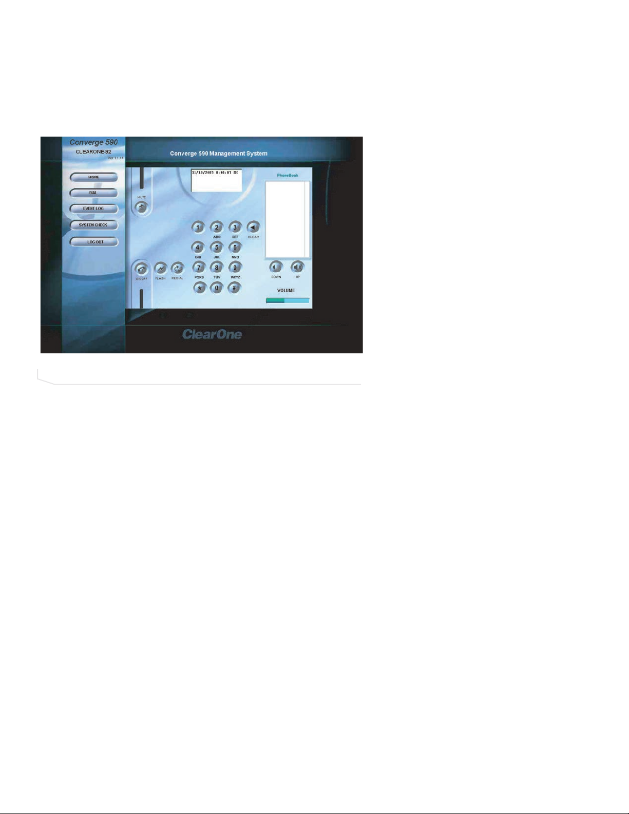
72 Technical Services: 800.283.5936
DIAL
You can make all your calls from the Dialer in the web interface. You can dial a number,
redial the last dialed call and disconnect calls. You can also use flash settings, mute the
microphones, adjust volume, and dial from the phonebook.
TO OPEN A DIALER WINDOW
1. Click the
Dial
button in the left channel navigation.
TO MAKE A CALL
1. Click the
ON/OFF
button to take the phone off-hook (indicator turns green).
2. Using the number pad, dial a phone number just as you would on a standard phone.
>
Note
: You can also pre-dial the number and press the
ON/OFF
button to connect the
call.
>
Tip
: You can also dial using the 0-9, star (*) and number (#) on your on your keyboard. Use the comma (,) key to enter a two second pause. The Enter key connects
to and disconnects from the telephone line.
TO MAKE A CALL FROM THE PHONEBOOK
1. Click a number in the Phonebook you want to call. The number appears in the display
window.
2. Click the
ON/OFF
button to dial the call or double-click on the entry.
FIGURE 5.2 Dialer window
Page 67

Using the Converge 73
TO END A CALL
1. Click the
ON/OFF
button.
TO REDIAL
1. Click the
REDIAL
button. The phone will automatically be taken off-hook and the last
dialed number will be called.
TO SEND A FLASH SIGNAL
1. If your telephone service includes call transfer, call waiting or conference calling, you
can use the Flash key. Refer to your local telephone service or PBX vendor for details.
TO MUTE/UNMUTE
1. Press the MUTE button to mute all microphones (the indicator turns red).
2. Press the MUTE button again to unmute all microphones (the indicator turns off).
TO ADJUST CALL VOLUME
1. Use the UPand
DOWN
volume buttons to adjust the volume to the desired level.
Page 68

74 Technical Services: 800.283.5936
EVENT LOG
The Event Log keeps record of a user-selectable events. You select the events you want
recorded in RAV-Ware. You then can download the log for review in the web interface.
Check the Event Log when there are communication errors or for other troubleshooting.
TO OPEN EVENT LOG
1. Click the
Event LLog
button in the menu pane.
TO CLEAR LOG
1. Click the
Clear LLog
button.
>
Note:
The log in RAV-Ware is also cleared.
TO DOWNLOAD LOG
1. Click the
Download LLog
button.
>
Note:
Right-click on the event log to save a copy to your hard drive as a .txt file.
FIGURE 5.3 Event log
Page 69

Using the Converge 75
SYSTEM CHECK
The System Checks window allows you to check your Converge system to be sure all
parts of your system are connected and working properly.
TO OPEN THE SYSTEM CHECKS
1. Click the
System CChecks
button.
TO RUN SYSTEM CHECKS
1. Click the
Start
button. Converge checks all components. When the check is complete,
lights will indicate the status of each component. Green indicates the part is
connected and functioning. Red indicates a problem with the component.
FIGURE 5.4 System checks
Page 70

76 Technical Services: 800.283.5936
LOG OUT
1. Click the
Log OOut
button.
2. Click
Yes, LLog OOut
or
No, GGo BBack
to return to the main screen.
FIGURE 5.5 Log out
Page 71

Appendix 77
MAINTENANCE
Unplug all components before cleaning. Do not use liquid or aerosol cleaners. Use a soft,
damp cloth to clean the microphones and controller.
If storing for an extended period of time, remove the batteries.
TROUBLESHOOTING
The following paragraphs describe ways to troubeshoot difficulties with your Converge
product, if necessary.
AUDIO
The following paragraphs outline audio troubleshooting.
No dial tone
Ensure that the RJ-11 cable is connected to an analog line. Make sure the phone cable is
connected to the Line jack, not the Set jack. If you are connected to a digital line through a
telephone handset, see page 21 for more information. Run a system diagnostic check
through RAV-Ware to be sure all Converge components are working properly.
Converge does not ring
Adjust the volume of the ringer. Check that the RJ-11 cable is connected. Verify that the
dialed phone number is correct.
Muffled reception
Check the connections of all audio inputs. Check the Audio Mixer in RAV-Ware to make
sure the correct audio paths are selected. Adjust the volume of the audio outputs.
Far-end party cannot hear
Do not move the microphones while on a call. Move any items that might be blocking the
microphones. Move closer to the microphones. Check mute on the inputs and outputs.
Short silences, echoes, or clipped speech on the far end
• Adjust the equalization in RAV-Ware for each component.
• Adjust the volume. Watch the meters. Make sure the loudest audio causes the meters
to just enter the yellow zone.
• Be sure equipment is placed correctly for the best sound performance. Refer to Chapter
1 for basic room design guidelines.
APPENDIX
Page 72

78 Technical Services: 800.283.5936
RF CONTROLLER
The following paragraphs outline RF controller troubleshooting.
Controller doesn’t communicate with the mixer
The RF Controller performs best when the Converge mixer is positioned within line of sight
and with the antenna pointed up. Check the signal strength indicator in all areas of the
room where the controller will be used.The signal strength indicator is on the LCD screen
and the maximum number of bars is four.
For optimal RF connectivity, make sure the signal strength measures two or four bars in all
operating locations (see figure 6.1). You can also use the RF Radio Test function on the
Controller for a more detailed signal strength measurement. Refer to page 63 for more
information.
To iimprove ssignal sstrength:
• Verify that the mixer is within line of sight.
• Install the mixer in the top space of the equipment rack.
• Ensure that the antenna is pointed up.
• Do not install the mixer in a metal cabinet.
You can also purchase a remote mount antenna to improve the signal strength when the
mixer is located in a different room or in an enclosed metal cabinet.
Part number: 910-153-050
Be sure the frequency setting on the controller is the same as the frequency setting in
RAV-Ware.
Cannot assign a speed dial number
Any phone numbers entered using the Controller are automatically assigned to speed dial
location 0. Access RAV-Ware to assign speed dial numbers.
FIGURE 6.1 Signal strength reliability
Signal Level Reliability
0–4 bars
Fai r
4–8 bars
9–12 bars
13–16 bars
Good
Better
Best
Page 73

Appendix 79
SPEAKERS
The following paragraphs outline speaker troubleshooting.
Neither speaker plays
Check that the wires are properly connected. Check the audio mixer in RAV-Ware to
ensure the audio is routed to the loudspeakers. Check volume setting and mute status.
Bass and treble are weak
Check the equalization for the loudspeakers in RAV-Ware.
Only one speaker plays
Check the equalization for the loudspeakers in RAV-Ware. Check the wires connected to
the speaker that does not play. Be sure the wires are in good condition and are firmly
connected.
One speaker still does not play
Disconnect the wires from both the speaker and the mixer. Disconnect the other wire from
its speaker and connect that end of the wire to the speaker that doesn't play. If the speaker
still doesn't play, the problem is in the speaker. If the speaker now plays, continue checking for the source of the problem. Disconnect the same wire from the mixer. Connect it to
the other output. If the speaker plays, the problem is the original wire that was connected
to that speaker.
GENERAL
The following paragraphs outline general troubleshooting.
Physical damage to Converge
All repairs must be done by a ClearOne technician. Call ClearOne technical support for
more information.
Page 74

80 Technical Services: 800.283.5936
CAMERA PINOUTS
Camera pinouts are provided in the following paragraphs.
8-PIN MINI DIN CONNECTOR
Pin Number Control Pin Number Control
1 RTS 5 RXD
2 CTS 6 TXD
3 TXD 7 not used
4 GND 8 not used
DB-9 CONNECTOR
Pin Number Control Pin Number Control
1 CD 6 DSR
2 RXD 7 RTS
3 TXD 8 CTS
4 DTR 9 RI
5 GND
8 Pin Mini DIN8 Pin Mini DIN
FIGURE 6.2 8-pin mini DIN connector pinouts
FIGURE 6.3 DB-9 connector pinouts
Pin 1 RTS
Pin 2 CTS
Pin 3 TXD
Pin 4 GND
Pin 5 RXD
Pin 6 TXD not used
Pin 7 Not used
Pin 8 Not used
Pin 2 CTS
Pin 1 RTS
Pin 5 RXD
Pin 4 GND
Pin 3 TXD
Pin 6 GND not used
Pin 7 Not used
Pin 8 Not used
8 Pin Mini DINDB-9
Pin 1 CD
Pin 2 RXD
Pin 3 TXD
Pin 4 DTR
Pin 5 GND
Pin 6 DSR
Pin 7 RTS
Pin 8 CTS
Pin 9 RI
Pin 2 CTS
Pin 3 TXD
Pin 5 RXD
Pin 4 GND
Pin 2 CTS
Pin 1 RTS
Pin 6 GND Not used
Pin 7 Not used
Pin 8 Not used
Page 75

SPECIFICATIONS
Appendix 81
DDiimmeennssiioonnss
MMiixxeerr
(WxDxH)
17" x 7.5" x 2"
(43.2 cm x 19.1 cm x 5.1 cm)
CCoonnttrroolllleerr
(WxDxH)
10.5" x 4.5" x 2.75"
WWeeiigghhtt
Mixer 4.5 lb (2.04 kg)
Controller 2.0 lb (.91 kg)
EEnnvviirroonnmmeennttaall
Operating Temperature:
32º to 122º F
0º to 50º C
PPoowweerr SSuuppppllyy
Primary Voltage: 100 to 240 VAC Auto sensing
50-60 Hz
AAuuddiioo PPeerrffoorrmmaannccee
Conditions: Unless otherwise specified, all
measurements are performed with a
22 Hz to 15 kHz BW limit (no weighting)
MMiiccrroopphho
onnee DDiissttrriibbuuttiioonn BBooxx::
Connection: F
emale XLR
Maximum Distance from Audio Mixer to Last Mic
Box: 60 ft.
Maximum Level: +17 dBu
Frequency Response: 20 Hz - 14 kHz (+/-1dB)
THD+N: < 0.01% (+14 dBu input @ 1 kHz)
Phantom Power: 24 V selectable
Impedence: 5 kOhm
LLiinnee IInnppuutt
Connection: Unbalanced RCA
Gain: -10 dBu nominal, adjustable from -14 dB to
+18 dB
Nominal Level: -10 dBu
Maximum Level: +9 dBu
Impedance: > 10 kOhm
LLiinnee OOuuttppuutt
Connection: Unbalanced RCA
Nominal Level: -10 dBu, adjustable from
-14 dB to +18 dB
Maximum Level: +9 dBu
Frequency Response: 40 Hz - 15 kHz
(+/-1dB)
Dynamic Range: > 80 dB
THD+N: < 0.02% (+6 dBu input @1 kHz)
PPllaayybbaacckk IInnppuutt
Connection: Unbalanced RCA
Gain: -10 dBu nominal, adjustable from
-14 dB to +18 dB
Nominal Level: -10 dBu
Maximum Level: +9 dBu
Impedance: > 10 kOhm
RReeccoorrdd OOuuttppuutt
Connection: Unbalanced RCA
Nominal Level: -10 dBu, adjustable from
-14 dB to +18 dB
Maximum Level: +9 dBu
Frequency Response: 40 Hz - 15 kHz
(+/-1dB)
Dynamic Range: > 80 dB
THD+N: < 0.02% (+6 dBu input @1 kHz)
LLoouuddssppeeaakkeerr
Connection: Push terminals with left and
right
Power: 15 Watts into 8 Ohm load
Impedance: 8 Ohm
Frequency Response: 60 Hz - 15 kHz
(+/-1 dB)
Dynamic Range: > 80 dB
THD+N: < 0.5% (+5 dBu line input
@1 kHz)
Output Level: 90 dBSPL output @ 1 meter
Page 76

82 Technical Services: 800.283.5936
MMiixxeerr
AEC tail time: 128 ms
Noise cancellation: (6 - 15 dB)
Gating: Adaptive ambient, 1st mic priority, look
ahead gating, NOM attenuation, manual on,
override on, chairman override.
TTeelleepphhoonnee IInntteerrffaaccee
Conditions: All measurements taken with
ALC disabled
Connection: RJ-11 (Set and Line Jacks)
Tail Time: 30 ms
Frequency Response: 250 Hz to 3.3 kHz (+/-1 dB)
THD+N: < 0.2% (+7 dBu line input @1 kHz)
Dynamic Range: > 60 dB
CCoommmmuunniiccaattiioonn II//OO
10/100 Ethernet Control Port:
RJ-45 with LED indicators for link, duplex and
activity status.
RRSS-223322 CCoonnttrrooll PPoorrtt::
DB9 female
9,600/19,200/38,400/57,600 (default)/115,200
Baud rate: 8 bits, 1 stop, no parity
Hardware flow control on (wireless default)/off
VVIISSCCAA CCaammeerraa PPoorrtt
DIN, 9600 baud, No Flow Control
UUSSBB 11..11 C
Coonnffiigguurraattiioonn PPoorrtt
Slave P
ort
Page 77

Appendix 83
SERIAL COMMANDS
The Converge 560 and Converge 590 accept serial commands through telnet, RS-232
serial port or USB. The commands in this manual pertain only to the Converge 560 and
Converge 590. RS-232 serial port protocol is 9,600, 19,200, 38,400, 57,600 (default) or
115,200 baud; 8 bits, 1 stop bit, no parity.
CONVENTIONS
The following typographic conventions are used in this document to describe the different
serial commands. Use the Command structure section and the examples as a guide when
creating your serial commands.
Convention Description
<X> Parameters enclosed in < > indicate a mandatory parameter.
[X] Parameters enclosed in [ ] indicate an optional parameter.
1-8 Parameters separated by a hyphen (-) indicate a range between the
values.
4,7,9 Parameters separated by a comma (,) indicate a list of available
values.
BAUD
Words in uppercase bold indicate command text.
DEVICE Indicates the device type and device ID.
COMMAND STRUCTURE
The following typographic conventions are used in this document to describe the different
serial commands. Use the Command structure section and the examples as a guide when
creating your serial commands.
Commands can be either UPPERCASE or lowercase. Also, extra spaces or tabs between
arguments in text commands are allowed. Return values are always uppercase. In order
for a command to be recognized by the serial port, the command must be terminated by a
carriage return.
The structure of serial commands is as follows:
#TYPE DEVICE COMMAND [X] [X]
# indicates the start of a command line
DEVICE represents the device type and device number
COMMAND is the command text
[X] [X] represents any additional options in the order that they appear in the
command descriptions that follow
* placed in the Type ID or Device ID fields, the command applies to all
units or all devices respectively.
Example:
A command to disable automatic gain control for Mic 2 on a Converge 560 device “0” will
have the command line: #C0 AGC 2 M 0. In this command line, C=Converge 560, 0=unit
0, AGC=command, 2=channel, M=Mic Input group, 0=off state. If a command calls for a
“null” value, leave a blank in the command line. For example, “#C0 AGC 2 M” will return
the current AGC state of Mic 2 on device C.
Command responses will have a carriage return line feed. For example, #C0 AGC 2 M O
carriage return line feed.
Page 78

84 Technical Services: 800.283.5936
GROUPS AND CHANNELS
The following tables define the relationship between alpha and numeric representations.
Text commands use the alpha designation, and binary commands use the numeric. In
addition, different groups have different allowable channel ranges.
TYPE AND DEVICE IDS
Type IID Unit ttype Device IID rrange
0xB Converge 590 0x0
0xC Converge 560 0x0
Group Alpha Number
FIGURE 6.4 Alpha and numeric representations
Unknown 0 N/A N/A
Outputs O 2 1 – 3
Microphones M 3 1 – 9 1 – 6
Line Inputs L 7 1 – 2
Unit
U 9 0 for Unit Values
Matrix
Transmit
Receive
Local Camera
X 11 TBD TBD
S 13 Phonebook 0
N 15 2 for HTML skin
T16 1 1
R17 1 1
V19
Converge 590
Channel Range
1 is Record Out
2 is Line Out
3 is Speaker Out
1 is Record In
2 is Aux In
1 for Log
3 for Firmware
4 for Directory
5 for Firmware Data
Sony Mode: 1–7
Canon Mode: 1–9
Converge 560
Channel Range
1 – 3
1 is Record Out
2 is Line Out
3 is Speaker Out
1 – 2
1 is Record In
2 is Aux In
0
1
Sony Mode: 1–7
Canon Mode: 1–9
Page 79

Appendix 85
METER TYPE DEFINITIONS
SERIAL COMMAND ERROR CODES
EErrrroorr nnuummbbeerr TTeexxtt mmeessssaaggee EExxppllaannaattiioonn//SSoolluuttiioonn
1 Memory error The box is out of internal memory.
Power cycle the box.
2 No command found A command was not found in the string.
3 Unknown command A command was executed on a different
device type that this box response can
not display. The command dictionary
needs to be updated.
4 Not implemented The command is not implemented.
5 Argument error The command had an argument that was
out of range.
6 Unknown command The command is unknown to this unit.
7 Bad checksum The binary command’s checksum is
wrong.
8 Camera not responding A preset or macro failed to program
because it is too large or because its
command list contained an invalid
command.
11 Command too big The binary command is too large.
Alpha Numeric Level position
FIGURE 6.5 Meter type definitions
A
R
E
T
for Mic Channel
2
Post Processing
Meter
after Signal
Processing Chain
5
Echo Return Loss N/A N/A N/A N/A
6
Echo Return Loss
7
ERL + ERLE
Level position
for Line Inputs
Level after PEQ
and gain
N/A N/A N/A N/A
N/A N/A N/A N/A
Level position
for Outputs
Level after PEQ
and gain
Level position
for Telco Transmits
Level after gain Level after gain
Level position
for Telco Receives
adjustment
Page 80

86 Technical Services: 800.283.5936
CONVERGE SERIAL COMMANDS
Command Function
AA Selects/reports setting of auto answer
AARINGS Selects/reports setting of the number of rings to auto answer
ACONN Selects/reports status of audible connect/disconnect indication
AD Selects/reports setting of auto disconnect
AEC Selects/reports acoustic echo canceller setting
AECREF Enables/disables or reports current status of AEC reference
AGC Selects/reports AGC
BATTERYLVL Reports battery level on remote
BAUD Selects/reports the baud rate of the serial port
CALLDUR Indicates how long a call has lasted
CAMBAUD Selects/reports baud rate of camera control port
CAMCTRLMODE Sets/reports camera control port mode
CAMFLOW Selects/reports flow control of camera control port
CAMMOVE Sends command to move the camera on the camera control port
CAMPRESET Executes camera preset
CAMPRESETSET Sets current position of camera as preset
CAMPRESETSET2 Sets/reports current camera preset
CAMPOSITION Sets/reports current position of camera on the camera control port
CAMSWITCHLAG Set the switch time lag for voice tracking
CAMTRACK Selects/reports camera voice-tracking mode
CAMZOOM Sets/reports current zoom of camera on the camera control port
CHAIRO Selects/reports the setting of chairman override for a mic input
CLEAREFFECT Enables/disables or reports current status of clear effect
CLOCK Sets/reports current time
COUNTRY Sets/reports country for compliance
DECAY Selects/reports the setting of the decay rate for a mic input
DEFAULT Sets the unit to default
DEVICE Selects/reports manufacturer identification label
DEVICETYPE Enables /disables or reports the current type of device connected to
an input or output
DIAL Dials DTMF sequence or reports last sequence dialed
DID Selects/reports device ID
ENETADDR Selects/reports IP address of the Ethernet port
ENETDHCP Selects/reports use of DHCP of the Ethernet port
ENETDNSA Selects/reports DNS server IP address of the Ethernet port
ENETDNS Selects/reports use of the DNS of the Ethernet port
ENETGATE Selects/reports default gateway of the Ethernet port
ENETSUBN Selects/reports subnet mask of the Ethernet port
EQ Enables/disables or reports current status of equalization
EQSEL Enables/disables or reports current status of equalization
FILTER Selects/reports the setting of filters for a mic input
FILTSEL Turns on and off the filters for a mic
FLOW Selects/reports the flow control of the serial port
GAIN Changes/reports gain for a channel
GATE Reports gate status of microphones
GHOLD Selects/reports the setting of the hold time for a mic input
GMODE Selects/reports the setting of the gating mode for a mic input
GRATIO Selects/reports the setting of the gate ratio for a mic input
Page 81

Appendix 87
CONVERGE SERIAL COMMANDS (CONTINUED)
Command Function
GREPORT Selects/reports gate status report frequency
HOOK Sends a hook flash
HOOKD Selects/reports hook flash duration
LABEL Selects/reports label of specified channel or unit
LOCALNUM Sets/reports current value of local number
LOGMASK Sets or reports the unit event log mask
LVL Reports in, out or processor level
LVLREPORT Selects/reports level status
LVLREPORTEN Enables/disables level reporting
MANUFACTURER Selects/reports manufacturer identification label
MICCAMPRESET Associate a microphone with a camera preset
MLINE Selects/reports the setting of coarse gain
MTRX Selects/reports matrix routing of an in to out
MUTE Sets/reports mute status
NCD Selects/reports the setting of noise cancellation for a mic input
NCSEL Enables/disables or reports current status of noise cancellation
NLP Selects/reports the setting of non-linear processing for each mic
channel
OFFA Selects/reports the off attenuation mode of a mic channel
PBDIAL Dials speed dial number by name
PHONEBOOKADD Saves entry in the phonebook
PHONEBOOKCNT Queries number of entries in phonebook
PHONEBOOKDEL Deletes an entry in the phonebook
PHONEBOOKREAD Queries an entry in the phonebook
PP Reports the setting of phantom power
REDIAL Redials last number called
RESET Resets the unit
RFFREQ Sets/reports frequency for RF link to remote
RING Indicates a ringing line
RINGERLVL Selects/reports audible ring level
RINGERSEL Sends/reports audible ring melody
RINGERTEST Plays current audible ringer melody
SILENCEPRST Associates camera preset with silence for voice tracking
SPEEDDIAL Dials speed dial number by speed dial number
SPLIFT Selects/reports the setting of the speech lift enable processing for
each mic channel
SPLEVEL Selects/reports the setting of the speech lift level for each mic
channel
STEREOMIX Enables/disables or reports stereo mix status
SYSCHECKS Initiates system checks
SYSRESULT Reports the results of the system check
TE Selects/reports hook status
TELCOLVLCTRL Selects/reports setting of Telco TX level control
TIMELOCALE Sets or reports the time locale settings
UCLOCK Sets or reports the current time.
UID Reports unit ID (read only)
VER Reports unit version (read only)
VOLUME Changes/reports the gain for the output channel
Page 82

88 Technical Services: 800.283.5936
AA - AUTO ANSWER ENABLE/ DISABLE
This command selects/reports the setting of auto answer.
AARRGGUUMMEENNTT DDEETTAAIILLSS
NNaammee TTyyppee SSiizzee VVaalluueess UUnniittss
Channel Channel 1 See Group and Channels
Group Group 1 17 (R)
Value Unsigned Integer 2 0 = Off
1 = On
2 = Toggle
(Null to query in text)
BBIINNAARRYY FFOORRMM DDEETTAAIILLSS
COMMAND ID:28
NUMBER OF ARGUMENTS:1
ARGUMENT FORM: <Channel><Group><Value>
TTEEXXTT FFOORRMM DDEETTAAIILLSS
COMMAND FORM: DEVICE
AAAA
<Channel> [Value]
AARINGS - NUMBER OF RINGS TO AUTO ANSWER ON
This command selects/reports the setting of the number of rings to auto answer.
AARRGGUUMMEENNTT DDEETTAAIILLSS
NNaammee TTyyppee SSiizzee VVaalluueess UUnniittss
Channel Channel 1 See Group and Channels
Group Group 1 17 (R)
Value Unsigned Integer 2 2 or 4
(Null to query in text)
BBIINNAARRYY FFOORRMM DDEETTAAIILLSS
COMMAND ID: 31
NUMBER OF ARGUMENTS: 1
ARGUMENT FORM: <Channel><Group><Value>
TTEEXXTT FFOORRMM DDEETTAAIILLSS
COMMAND FORM: DEVICE
AAAARRIINNGGSS
<Channel> [Value]
Page 83

Appendix 89
ACONN - AUDIBLE CONNECT / DISCONNECT INDICATION
This command selects/reports the status of the audible connect/disconnect indication.
AARRGGUUMMEENNTT DDEETTAAIILLSS
NNaammee TTyyppee SSiizzee VVaalluueess UUnniittss
Channel Channel 1 See Group and Channels
Group Group 1 17 (R)
Value Unsigned Integer 2 0 = Off
1 = On
2 = Toggle
(Null to query in text)
BBIINNAARRYY FFOORRMM DDEETTAAIILLSS
COMMAND ID:96
NUMBER OF ARGUMENTS:1
ARGUMENT FORM: <Channel><Group><Value>
TTEEXXTT FFOORRMM DDEETTAAIILLSS
COMMAND FORM: DEVICE
AACCOONNNN
<Channel> [Value]
AD - AUTO DISCONNECT ENABLE/ DISABLE
This command selects/reports the setting of auto disconnect.
AARRGGUUMMEENNTT DDEETTAAIILLSS
NNaammee TTyyppee SSiizzee VVaalluueess UUnniittss
Channel Channel 1 See Group and Channels
Group Group 1 17 (R)
Value Unsigned Integer 2 0 = Off
1 = Loop Drop
2 = Call Progress
3 = Loop Drop + Call Progress
(Null to query in text)
BBIINNAARRYY FFOORRMM DDEETTAAIILLSS
COMMAND ID:29
NUMBER OF ARGUMENTS:1
ARGUMENT FORM: <Channel><Group><Value>
TTEEXXTT FFOORRMM DDEETTAAIILLSS
COMMAND FORM: DEVICE
AADD
<Channel> [Value]
Page 84

90 Technical Services: 800.283.5936
AEC - ACOUSTIC ECHO CANCELLER ENABLE/ DISABLE
This command selects/reports the setting of Acoustic Echo Canceller.
AARRGGUUMMEENNTT DDEETTAAIILLSS
NNaammee TTyyppee SSiizzee VVaalluueess UUnniittss
Channel Channel 1 See Group And Channels
Group Group 1 3 (M)
Value Unsigned Integer 2 0 = Off
1 = On
2 = Toggle(Null to query in text)
BBIINNAARRYY FFOORRMM DDEETTAAIILLSS
COMMAND ID:27
NUMBER OF ARGUMENTS:1
ARGUMENT FORM: <Channel><Group><Value>
TTEEXXTT FFOORRMM DDEETTAAIILLSS
COMMAND FORM: DEVICE
AAEECC
<Channel> [Value]
AECREF - ACOUSTIC ECHO CANCELLATION REFERENCE
This command enables/disables or reports the current status of the AEC reference.
AARRGGUUMMEENNTT DDEETTAAIILLSS
NNaammee TTyyppee SSiizzee VVaalluueess UUnniittss
Value Unsigned Integer 4 1 - 3
(Null to query in text)
BBIINNAARRYY FFOORRMM DDEETTAAIILLSS
COMMAND ID:68
NUMBER OF ARGUMENTS:1
ARGUMENT FORM: <Value>
TTEEXXTT FFOORRMM DDEETTAAIILLSS
COMMAND FORM: DEVICE
AAEECCRREEFF
[Value]
Page 85

Appendix 91
AGC - AUTOMATIC GAIN CONTROL
This command selects/reports the setting of automatic gain control.
AARRGGUUMMEENNTT DDEETTAAIILLSS
NNaammee TTyyppee SSiizzee VVaalluueess UUnniittss
Channel Channel 1 See Group And Channels
Group Group 1 3 (M)
Value Unsigned Integer 2 0 = Off
1 = On
2 = Toggle
(Null to query in text)
BBIINNAARRYY FFOORRMM DDEETTAAIILLSS
COMMAND ID:1
NUMBER OF ARGUMENTS:1
ARGUMENT FORM: <Channel><Group><Value>
TTEEXXTT FFOORRMM DDEETTAAIILLSS
COMMAND FORM: DEVICE
AAGGCC
<Channel> <Group> [Value]
BATTERYLVL - BATTERY LEVEL
This command reports the battery level on the remote. If the batteries run low, this command will auto-
matically be sent out reporting the low indication.
AARRGGUUMMEENNTT DDEETTAAIILLSS
NNaammee TTyyppee SSiizzee VVaalluueess UUnniittss
Value Unsigned Integer 4 0 = battery level unavailable
1 = Lowest
2
3
4
5 = Highest
(Null to query in text.)
BBIINNAARRYY FFOORRMM DDEETTAAIILLSS
COMMAND ID:65
NUMBER OF ARGUMENTS:1
ARGUMENT FORM: <Value>
TTEEXXTT FFOORRMM DDEETTAAIILLSS
COMMAND FORM DEVICE
BBAATTTTEERRYYLLVVLL
[Value]
Page 86

92 Technical Services: 800.283.5936
BAUD - BAUD RATE
This command selects/reports the baud rate of the serial port.
AARRGGUUMMEENNTT DDEETTAAIILLSS
NNaammee TTyyppee SSiizzee VVaalluueess UUnniittss
Value Unsigned Integer 4 9600, 19200, 38400,
57600,115200
(Null to query in text)
BBIINNAARRYY FFOORRMM DDEETTAAIILLSS
COMMAND ID:2
NUMBER OF ARGUMENTS:1
ARGUMENT FORM: <Value>
TTEEXXTT FFOORRMM DDEETTAAIILLSS
COMMAND FORM: DEVICE
BBAAUUDD
[Value]
AAtttteennttiioonn
: If you are connected to the Converge unit through the serial port, you will need to
reboot the unit before the baud rate and flow control changes take place. If you are connected to
the Converge unit through the USB port, changes are made instantly.
CALLDUR - CALL DURATION
This command indicates how long a call has lasted. If no call is in session, this will report 0. At the time
of call termination, this command will automatically be sent out reporting the duration.
AARRGGUUMMEENNTT DDEETTAAIILLSS
NNaammee TTyyppee SSiizzee VVaalluueess UUnniittss
Channel Channel 1 See Group And Channels
Group Group 1 17 (R)
Reserved 2 0
Duration String 8 String of format
HR:MN:SS
BBIINNAARRYY FFOORRMM DDEETTAAIILLSS
COMMAND ID:63
NUMBER OF ARGUMENTS:3
ARGUMENT FORM: <Channel><Group><Reserved><Duration>
TTEEXXTT FFOORRMM DDEETTAAIILLSS
COMMAND FORM: DEVICE
CCAALLLLDDUURR
<Channel> <Duration>
Page 87

Appendix 93
CAMBAUD - CAMERA CONTROL BAUD RATE
This command selects/reports the baud rate of the camera control serial port.
AARRGGUUMMEENNTT DDEETTAAIILLSS
NNaammee TTyyppee SSiizzee VVaalluueess UUnniittss
Value Unsigned Integer 4 2400, 9600, 19200, 38400
(Null to query in text)
BBIINNAARRYY FFOORRMM DDEETTAAIILLSS
COMMAND ID:60
NUMBER OF ARGUMENTS:1
ARGUMENT FORM: <Value>
TTEEXXTT FFOORRMM DDEETTAAIILLSS
COMMAND FORM: DEVICE
CCAAMMBBAAUUDD
[Value]
CAMCTRLMODE - CAMERA CONTROL PORT MODE
This command sets/reports the camera control port mode.
AARRGGUUMMEENNTT DDEETTAAIILLSS
NNaammee TTyyppee SSiizzee VVaalluueess UUnniittss
Value Unsigned Integer 4 0 = Sony
1 = Canon
(Null to Query in Text)
BBIINNAARRYY FFOORRMM DDEETTAAIILLSS
COMMAND ID:50
NUMBER OF ARGUMENTS:1
ARGUMENT FORM: <Value>
TTEEXXTT FFOORRMM DDEETTAAIILLSS
COMMAND FORM: DEVICE
CCAAMMCCTTRRLLMMOODDEE
[Value]
Page 88

94 Technical Services: 800.283.5936
CAMFLOW - CAMERA CONTROL FLOW CONTROL
This command selects/reports the flow control of the camera control serial port on the unit. Hardware
flow control is implemented using DTR and DSR.
AARRGGUUMMEENNTT DDEETTAAIILLSS
NNaammee TTyyppee SSiizzee VVaalluueess UUnniittss
Value Unsigned Integer 4 0 = Off
1 = On
2 = Toggle
(Null to query in text)
BBIINNAARRYY FFOORRMM DDEETTAAIILLSS
COMMAND ID:61
NUMBER OF ARGUMENTS:1
ARGUMENT FORM: <Value>
TTEEXXTT FFOORRMM DDEETTAAIILLSS
COMMAND FORM: DEVICE
CCAAMMFFLLOOWW
[Value]
CAMMOVE - MOVE THE CAMERA
This command sends commands to move the camera on the camera control port. There is no query
for this command.
AARRGGUUMMEENNTT DDEETTAAIILLSS
NNaammee TTyyppee SSiizzee VVaalluueess UUnniittss
Channel Channel 1 See Group And Channels
Group Group 1 19 (V)
Value Unsigned Integer 2 0 = Stop
1 = Pan Right
2 = Pan Left
3 = Tilt Up
4 = Tilt Down
5 = Zoom In
6 = Zoom Out
BBIINNAARRYY FFOORRMM DDEETTAAIILLSS
COMMAND ID:49
NUMBER OF ARGUMENTS:1
ARGUMENT FORM: <Channel><Group><Value>
TTEEXXTT FFOORRMM DDEETTAAIILLSS
COMMAND FORM: DEVICE
CCAAMMMMOOVVEE
<Channel Group> [Value]
Page 89

Appendix 95
CAMPRESET - CAMERA PRESET
Executes a camera preset. There is no query for this command.
AARRGGUUMMEENNTT DDEETTAAIILLSS
NNaammee TTyyppee SSiizzee VVaalluueess UUnniittss
Value Unsigned Integer 4 1 - 10
BBIINNAARRYY FFOORRMM DDEETTAAIILLSS
COMMAND ID:51
NUMBER OF ARGUMENTS:1
ARGUMENT FORM: <Value>
TTEEXXTT FFOORRMM DDEETTAAIILLSS
COMMAND FORM: DEVICE
CCAAMMPPRREESSEETT
[Value]
CAMPRESETSET - CAMERA PRESET SETUP
This command sets the current position of a camera as a camera preset. There is no query for this
command.
AARRGGUUMMEENNTT DDEETTAAIILLSS
NNaammee TTyyppee SSiizzee VVaalluueess UUnniittss
Preset Unsigned Integer 2 1 - 10
Channel Channel 1 See Group and Channels
Group Group 1 19 (V)
Label String 16
BBIINNAARRYY FFOORRMM DDEETTAAIILLSS
COMMAND ID:52
NUMBER OF ARGUMENTS:5
ARGUMENT FORM: <Preset><Channel><Group><Label>
TTEEXXTT FFOORRMM DDEETTAAIILLSS
COMMAND FORM: DEVICE
CCAAMMPPRREESSEETTSSEETT
<Preset Channel Group Label>
Page 90

96 Technical Services: 800.283.5936
CAMPRESETSET2 - CAMERA PRESET SETUP 2
This command sets or reports the current camera preset.
ARGU
MENT DETAILS
NNaammee TTyyppee SSiizzee VVaalluueess UUnniittss
Preset Unsigned Integer 2 1 - 10
Channel Channel 1 See Group and Channels
Group Group 1 19 (V)
Pan Angle Signed Float 2 If Sony, -100 to 100. Degrees
If Canon, -100 to 100.
(NULL to Query in Text)
Tilt Angle Signed Float 2 If Sony, -25 to 25. Degrees
If Canon, -30 to 90
Zoom Angle Signed Float 4 If Sony, 6.6 to 65. Degrees
If Canon, 3 to 47.5.
Label String 16
BINARY FORM DETAILS
COMMAND ID:56
NUMBER OF ARGUMENTS:7
ARGUMENT FORM: <Preset><Channel><Group><Pan><Tilt><Zoom><Label>
TEXT FORM DETAILS
COMMAND FORM: DEVICE
CCAAMMPPRREESSEETTSSEETT22
<Preset>[Channel Group Pan Tilt Zoom Label]
CAMPOSITION - CAMERA POSITION
This command sets or reports the current position of the camera on the camera control port.
AARRGGUUMMEENNTT DDEETTAAIILLSS
NNaammee TTyyppee SSiizzee VVaalluueess UUnniittss
Channel Channel 1 See Group and Channels
Group Group 1 19 (V)
Pan Angle Signed Float 2 If Sony, -100 to 100. Degrees
If Canon, -100 to 100.
(NULL to Query in Text)
Tilt Angle Signed Float 4 If Sony, -25 to 25. Degrees
If Canon, -30 to 30.
BBIINNAARRYY FFOORRMM DDEETTAAIILLSS
COMMAND ID:53
NUMBER OF ARGUMENTS:2
ARGUMENT FORM: <Channel><Group><Pan Angle><Tilt Angle>
TTEEXXTT FFOORRMM DDEETTAAIILLSS
COMMAND FORM: DEVICE
CCAAMMPPOOSSIITTOONN
<Channel Group> [Pan Tilt]
Page 91

Appendix 97
CAMSWITCHLAG - CAMERA SWITCH TIME LAG
This command set the switch time lag for voice tracking.
AARRGGUUMMEENNTT DDEETTAAIILLSS
NNaammee TTyyppee SSiizzee VVaalluueess UUnniittss
Value Unsigned Float 4 0.00 - 5.00 S
BBIINNAARRYY FFOORRMM DDEETTAAIILLSS
COMMAND ID:76
NUMBER OF ARGUMENTS:1
ARGUMENT FORM: <Value>
TTEEXXTT FFOORRMM DDEETTAAIILLSS
COMMAND FORM: DEVICE
CCAAMMSSWWIITTCCHHLLAAGG
[Value]
CAMTRACK - CAMERA TRACK
This command selects/reports the camera voice tracking mode.
AARRGGUUMMEENNTT DDEETTAAIILLSS
NNaammee TTyyppee SSiizzee VVaalluueess UUnniittss
Value Unsigned Integer 4 0 = Off
1 = On
2 = Toggle
(Null to query in text)
BBIINNAARRYY FFOORRMM DDEETTAAIILLSS
COMMAND ID:57
NUMBER OF ARGUMENTS:1
ARGUMENT FORM: <Value>
TTEEXXTT FFOORRMM DDEETTAAIILLSS
COMMAND FORM: DEVICE
CCAAMMTTRRAACCKK
[Value]
Page 92

98 Technical Services: 800.283.5936
CAMZOOM - CAMERA ZOOM
This command sets or reports the current Zoom of the camera on the camera control port.
AARRGGUUMMEENNTT DDEETTAAIILLSS
NNaammee TTyyppee SSiizzee VVaalluueess UUnniittss
Channel Channel 1 See Group and Channels
Group Group 1 19 (V)
Zoom Angle Signed Float 2 If Sony, 6.6 to 65. Degrees
If Canon, 3 to 47.5.
(NULL to Query in Text).
BBIINNAARRYY FFOORRMM DDEETTAAIILLSS
COMMAND ID:54
NUMBER OF ARGUMENTS:1
ARGUMENT FORM: <Channel><Group><Zoom Angle>
TTEEXXTT FFOORRMM DDEETTAAIILLSS
COMMAND FORM: DEVICE
CCAAMMZZOOOOMM
<Channel Group> [Zoom]
CHAIRO - CHAIRMAN OVERRIDE MODE
This command selects/reports the setting of the chairman override for a microphone input.
AARRGGUUMMEENNTT DDEETTAAIILLSS
NNaammee TTyyppee SSiizzee VVaalluueess UUnniittss
Channel Unsigned Integer 8 See Group and Channels
Group Unsigned Integer 8 3
Value Unsigned Integer 16 0 = chairman overrid off
1 = chairman override on
2 = toggle
(Null to return current mode)
BBIINNAARRYY FFOORRMM DDEETTAAIILLSS
COMMAND ID: 114
NUMBER OF ARGUMENTS:1
ARGUMENT FORM: <Channel><Group> [Value]
TTEEXXTT FFOORRMM DDEETTAAIILLSS
COMMAND FORM: DEVICE
CCHHIIAARROO
<Channel> [Value]
Page 93

Appendix 99
CAMTRACK - CAMERA TRACK
This command selects/reports the camera voice tracking mode.
AARRGGUUMMEENNTT DDEETTAAIILLSS
NNaammee TTyyppee SSiizzee VVaalluueess UUnniittss
Value Unsigned Integer 4 0 = Off
1 = On
2 = Toggle
(Null to query in text)
BBIINNAARRYY FFOORRMM DDEETTAAIILLSS
COMMAND ID:57
NUMBER OF ARGUMENTS:1
ARGUMENT FORM: <Value>
TTEEXXTT FFOORRMM DDEETTAAIILLSS
COMMAND FORM: DEVICE
CCAAMMTTRRAACCKK
[Value]
CLEAREFFECT - CLEAR EFFECT WIDE BAND TELCO EMULATION
This command enables/disables or reports the current status of the clear effect.
AARRGGUUMMEENNTT DDEETTAAIILLSS
NNaammee TTyyppee SSiizzee VVaalluueess UUnniittss
Channel Channel 1 See Group and Channels
Group Group 1 17 (T)
Value Unsigned Integer 2 0 = Off
1 = On
2 = Toggle
(Null to query in text)
BBIINNAARRYY FFOORRMM DDEETTAAIILLSS
COMMAND ID:66
NUMBER OF ARGUMENTS:1
ARGUMENT FORM: <Channel><Group><Value>
TTEEXXTT FFOORRMM DDEETTAAIILLSS
COMMAND FORM: DEVICE
CCLLEEAARREEFFFFEECCTT
<Channel> [Value]
Page 94

100 Technical Services: 800.283.5936
CLOCK - CLOCK SET
This command sets or reports the current time.
AARRGGUUMMEENNTT DDEETTAAIILLSS
NNaammee TTyyppee SSiizzee VVaalluueess UUnniittss
Date Unsigned Integer 1 1 - 31
Month Unsigned Integer 1 1 - 12
Year Unsigned Integer 2 2000 - 2099
(NULL to Query in Text)
Hours Unsigned Integer 1 00 - 23
Minutes Unsigned Integer 1 00 - 59
Seconds Unsigned Integer 1 00 - 59
Day of Week Unsigned Integer 1 1 = Sunday
2 = Monday
3 = Tuesday
4 = Wednesday
5 = Thursday
6 = Friday
7 = Saturday
BBIINNAARRYY FFOORRMM DDEETTAAIILLSS
COMMAND ID:64
NUMBER OF ARGUMENTS:2
ARGUMENT FORM: <Date><Month><Year><Hours><Minutes><Seconds><Day>
TTEEXXTT FFOORRMM DDEETTAAIILLSS
COMMAND FORM: DEVICE
CCLLOOCCKK
[Date Month Year Hours Minutes Seconds Day]
Page 95

Appendix 101
COUNTRY - COUNTRY SELECTION
This command sets/reports the country for compliance.
AARRGGUUMMEENNTT DDEETTAAIILLSS
NNaammee TTyyppee SSiizzee VVaalluueess UUnniittss
Value Unsigned Integer 4 1 = US / Canada
2 = Europe
3 = Mexico
4 = Australia / New Zealand
5 = South Africa
6 = Japan
7 = Brazil
8 = South Korea
9 = China
10 = Singapore
11 = Taiwan
(Null to query in text)
BBIINNAARRYY FFOORRMM DDEETTAAIILLSS
COMMAND ID:40
NUMBER OF ARGUMENTS:1
ARGUMENT FORM: <Value>
TTEEXXTT FFOORRMM DDEETTAAIILLSS
COMMAND FORM: DEVICE
CCOOUUNNTTRRYY
[Value]
DEFAULT - DEFAULT THE UNIT
Sets the unit to factory defaults. There is no query for this command.
AARRGGUUMMEENNTT DDEETTAAIILLSS
None
BBIINNAARRYY FFOORRMM DDEETTAAIILLSS
COMMAND ID:17
NUMBER OF ARGUMENTS:1
ARGUMENT FORM: <0>
TTEEXXTT FFOORRMM DDEETTAAIILLSS
COMMAND FORM: DEVICE
DDEEFFAAUULLTT
AAtttteennttiioonn
: The unit will need to be rebooted after sending the DEFAULT command.
Page 96

102 Technical Services: 800.283.5936
DECAY - DECAY ADJUST
This command selects/reports the setting of the decay rate for a microphone input.
AARRGGUUMMEENNTT DDEETTAAIILLSS
NNaammee TTyyppee SSiizzee VVaalluueess UUnniittss
Channel Unsigned Integer 8 See Group and Channels
Group Unsigned Integer 8 3
Value Unsigned Integer 16 1 = slow
2 = medium
3 = fast
(Null to return the current decay rate)
BBIINNAARRYY FFOORRMM DDEETTAAIILLSS
COMMAND ID: 113
NUMBER OF ARGUMENTS:1
ARGUMENT FORM: <Channel><Group><Value>
TTEEXXTT FFOORRMM DDEETTAAIILLSS
COMMAND FORM: DEVICE
DDEECCAAYY
<Channel> [Value]
DEVICE - DEVICE IDENTIFICATION LABEL
This selects/reports the manufacturer identification label of the specific channel.
AARRGGUUMMEENNTT DDEETTAAIILLSS
NNaammee TTyyppee SSiizzee VVaalluueess UUnniittss
Channel Channel 1 See Group and Channels
Group Group 1 2, 3, 7(O, M, L)
Reserved Unsigned Integer 2 0
Label String 32 1 - 32 characters
CLEAR = clear the label
(Null to query in text)
BBIINNAARRYY FFOORRMM DDEETTAAIILLSS
COMMAND ID:82
NUMBER OF ARGUMENTS:9
ARGUMENT FORM: <Channel><Group><Reserved><Value>
TTEEXXTT FFOORRMM DDEETTAAIILLSS
COMMAND FORM: DEVICE
DDEEVVIICCEE
<Channel> <Group> [Value]
Page 97

Appendix 103
DEVICETYPE - SETS THE TYPE OF DEVICE CONNECTED TO AN INPUT OR
OUTPUT
This command enables / disables or reports the current type of device connected to an input or out-
put.
AARRGGUUMMEENNTT DDEETTAAIILLSS
NNaammee TTyyppee SSiizzee VVaalluueess UUnniittss
Channel Channel 1 See Group and Channels
Group Group 1 2, 7 (O, L)
Value Unsigned Integer 2 0 = 1 = 2 = 3 = 4 = (NULL to query in text)
BBIINNAARRYY FFOORRMM DDEETTAAIILLSS
COMMAND ID: 85
NUMBER OF ARGUMENTS:1
ARGUMENT FORM: <Channel><Group><Value>
TTEEXXTT FFOORRMM DDEETTAAIILLSS
COMMAND FORM: DEVICE
DDEEVVIICCEETTYYPPEE
<Channel> <Group> [Value]
DIAL - DTMF DIALING
This command dials a DTMF sequence or reports back the last sequence dialed.
AARRGGUUMMEENNTT DDEETTAAIILLSS
NNaammee TTyyppee SSiizzee VVaalluueess UUnniittss
Channel Channel 1 See Group and Channels
Group Group 1 17 (R)
Reserved 2 0
Number String 44 1 - 44 Chars of '0' - '9', 'A' - 'D', '*', '#', ','
(Null to query last number dialed in text)
Note: A "," (comma) equals a two second pause.
BBIINNAARRYY FFOORRMM DDEETTAAIILLSS
COMMAND ID:30
NUMBER OF ARGUMENTS:12
ARGUMENT FORM: <Channel><Group><Number>
TTEEXXTT FFOORRMM DDEETTAAIILLSS
COMMAND FORM: DEVICE
DDIIAALL
<Channel> [Number]
Page 98

104 Technical Services: 800.283.5936
DID - DEVICE ID
This command reports the device ID. This command is read-only.
AARRGGUUMMEENNTT DDEETTAAIILLSS
NNaammee TTyyppee SSiizzee VVaalluueess UUnniittss
Value Unsigned Integer 4 See Type and Device IDs
(Null sent in text, Value returned)
BBIINNAARRYY FFOORRMM DDEETTAAIILLSS
COMMAND ID:3
NUMBER OF ARGUMENTS:1
ARGUMENT FORM: <Value>
ENETADDR - ETHERNET PORT IP ADDRESS
This command selects/reports the IP address of the Ethernet port on the unit.
AARRGGUUMMEENNTT DDEETTAAIILLSS
NNaammee TTyyppee SSiizzee VVaalluueess UUnniittss
Value IP Address 4 (Null to query in text)
BBIINNAARRYY FFOORRMM DDEETTAAIILLSS
COMMAND ID:21
TTEEXXTT FFOORRMM DDEETTAAIILLSS
COMMAND FORM: DEVICE
DDIIDD
[Value]
NUMBER OF ARGUMENTS:1
ARGUMENT FORM: <Value>
TTEEXXTT FFOORRMM DDEETTAAIILLSS
COMMAND FORM: DEVICE
EENNEETTAADDDDRR
[Value]
ENETDHCP - ETHERNET DHCP SELECTION
This command selects/reports the use of DHCP of the Ethernet port on the unit.
AARRGGUUMMEENNTT DDEETTAAIILLSS
NNaammee TTyyppee SSiizzee VVaalluueess UUnniittss
Value Unsigned Integer 4 0 = On
1 = Off
2 = Toggle
(Null to query in text)
BBIINNAARRYY FFOORRMM DDEETTAAIILLSS
COMMAND ID:25
NUMBER OF ARGUMENTS:1
ARGUMENT FORM: <Value>
TTEEXXTT FFOORRMM DDEETTAAIILLSS
COMMAND FORM: DEVICE
EENNEETTDDHHCCPP
[Value]
Page 99

Appendix 105
ENETDNSA - ETHERNET DNS SERVER ADDRESSES
This command selects/reports the DNS servers IP addresses of the Ethernet port on the unit.
AARRGGUUMMEENNTT DDEETTAAIILLSS
NNaammee TTyyppee SSiizzee VVaalluueess UUnniittss
Value IP Address 4 (Null to query in text)
BBIINNAARRYY FFOORRMM DDEETTAAIILLSS
COMMAND ID:24
NUMBER OF ARGUMENTS:1
ARGUMENT FORM: <Value>
TTEEXXTT FFOORRMM DDEETTAAIILLSS
COMMAND FORM: DEVICE
EENNEETTDDNNSSAA
[Value]
ENETDNS - ETHERNET DNS SELECTION
This command selects/reports the use of DNS of the Ethernet port on the unit.
AARRGGUUMMEENNTT DDEETTAAIILLSS
NNaammee TTyyppee SSiizzee VVaalluueess UUnniittss
Value Unsigned Integer 4 0 = On
1 = Off
2 = Toggle
(Null to query in text)
BBIINNAARRYY FFOORRMM DDEETTAAIILLSS
COMMAND ID:26
NUMBER OF ARGUMENTS:1
ARGUMENT FORM: <Value>
TTEEXXTT FFOORRMM DDEETTAAIILLSS
COMMAND FORM: DEVICE
EENNEETTDDNNSS
[Value]
ENETGATE - ETHERNET DEFAULT GATEWAY ADDRESS
This command selects/reports the default gateway of the Ethernet port on the unit.
AARRGGUUMMEENNTT DDEETTAAIILLSS
NNaammee TTyyppee SSiizzee VVaalluueess UUnniittss
Value IP Address 4 (Null to query in text)
BBIINNAARRYY FFOORRMM DDEETTAAIILLSS
COMMAND ID:23
NUMBER OF ARGUMENTS:1
ARGUMENT FORM: <Value>
TTEEXXTT FFOORRMM DDEETTAAIILLSS
COMMAND FORM: DEVICE
EENNEETTGGAATTEE
[Value]
Page 100

106 Technical Services: 800.283.5936
ENETSUBN - ETHERNET SUBNET MASK
This command selects/reports the Subnet mask of the Ethernet port on the unit.
AARRGGUUMMEENNTT DDEETTAAIILLSS
NNaammee TTyyppee SSiizzee VVaalluueess UUnniittss
Value IP Address 4 (Null to query in text)
BBIINNAARRYY FFOORRMM DDEETTAAIILLSS
COMMAND ID:22
NUMBER OF ARGUMENTS:1
ARGUMENT FORM: <Value>
TTEEXXTT FFOORRMM DDEETTAAIILLSS
COMMAND FORM: DEVICE
EENNEETTSSUUBBNN
[Value]
EQ - EQUALIZATION
This command enables/disables or reports the current status of the equalization on the input or output.
AARRGGUUMMEENNTT DDEETTAAIILLSS
NNaammee TTyyppee SSiizzee VVaalluueess UUnniittss
Channel Channel 1 See Group and Channels
Group Group 1 2, 7 (O, L)
High Gain Signed Float 2 -12.00 - 12.00
(Null to query in text)
Mid Gain Signed Float 2 -12.00 - 12.00
Low Gain Signed Float 2 -12.00 - 12.00
BBIINNAARRYY FFOORRMM DDEETTAAIILLSS
COMMAND ID:67
NUMBER OF ARGUMENTS:2
ARGUMENT FORM: <Channel><Group><High Gain><Mid Gain><Low Gain>
TTEEXXTT FFOORRMM DDEETTAAIILLSS
COMMAND FORM: DEVICE
EEQQ
<Channel> <Group> [High Mid Low]
 Loading...