

Page 1
Collaborate™ - Conferencing Solutions
In s t a l l a t I o n Gu I d e
Page 2

Table of Contents
COLLABORATE CONFERENCING SOLUTIONS
Tools Needed But Not Included ............................................................................................................................................1
Basic Collaborate Solution ...................................................................................................................................................1
COLLABORATE OVERVIEW
Cable Connections ...............................................................................................................................................................2
Foot Stand Assembly (Single Monitor) .................................................................................................................................3
Foot Stand Assembly (Dual Monitor)....................................................................................................................................5
WALL-MOUNT ASSEMBLY OVERVIEW
Wall-Mount Kit .......................................................................................................................................................................7
Wall-Mount Assembly (Single Monitor).................................................................................................................................8
Wall-Mount Assembly (Dual Monitor) ...................................................................................................................................9
MEDIA STAND ASSEMBLY OVERVIEW
Soundbar Installation ..........................................................................................................................................................11
HD Camera Installation .......................................................................................................................................................11
TITAN DUAL ARTICULATING ARM ASSEMBLY OVERVIEW
Soundbar Installation ..........................................................................................................................................................13
HD Camera Installation .......................................................................................................................................................13
HD CAMERA TOPOLOGY
5.5 mm HD Camera ............................................................................................................................................................15
SOFTWARE INSTALLATION
Installing the OS ..................................................................................................................................................................16
Installing Collaborate Console ............................................................................................................................................16
COMPLIANCE
SPECIFICATIONS
Page 3
COLLABORATE CONFERENCING SOLUTIONS
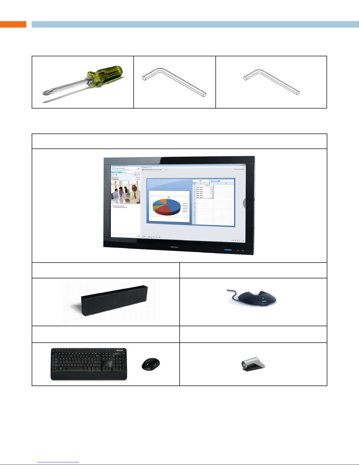
to o l s ne e d e d Bu t no t In c l u d e d
Ba s I c co l l a B o r a t e so l u t I o n
5 mm
Collaborate Console
3 mm
Collaborate Soundbar Collaborate Microphone
* Additional Mic Pod available for purchase - System maximum of two total.
Wireless Keyboard and Mouse HD USB Camera
CAUTION : The Console weighs about 100 lb. Please take all necessary precautions
when lifting. ClearOne recommends only lifting and moving the Collaborate with a
team of two or more people.
In s t a l l a t I o n Gu I d e 1
Page 4
COLLABORATE OVERVIEW
CAUTION : When placing the monitor(s) face-down, ensure the surface is flat, clean,
soft and is non-abrasive to prevent scratch and/or scuff damage. ClearOne is not
responsible for damage to monitor(s) caused by abrasive surface work area.
There are three options available for setting up the Collaborate system:
Option 1: Foot Stand system - Single or dual monitor system.
Option 2: Wall Mount system - Accessory kit available for a dual monitor Wall Mount system.
Option 3: Dual Articulating Arm Cart or Media Stand system
Please contact ClearOne for more details on pricing and shipping of any of the Collaborate
accessory kits.
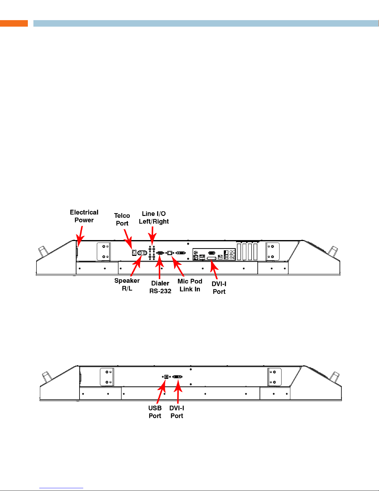
ca B l e co n n e c t I o n s
When possible, make sure all system connections are made prior to installing the soundbar and
performing the final placement of the system. The System Ports are more accessible when the
monitor is face-down during assembly. It is recommended making all cable connections at the time
of assembly.
Collaborate Console
In a dual monitor system, connections are made between the Collaborate Console shown above
and the Collaborate Display using the respective ports (Console USB and DVI-I ports shown above
to Display USB and DVI-I ports shown below).
Collaborate Display
2 te c h n I c a l su p p o r t : 800.283.5936
Page 5
Fo o t st a n d as s e m B l y (sI n G l e mo n I t o r )
CAUTION : The feet are installed with the monitor face down. Make sure the face of
the monitor rests on a flat, clean, soft, non-abrasive surface to prevent any damage
to monitor screen. Also, due to the weight of the monitor, make sure a team of two
or more people are available when moving the Console and/or Display to prevent
personal injury or damage to the product.
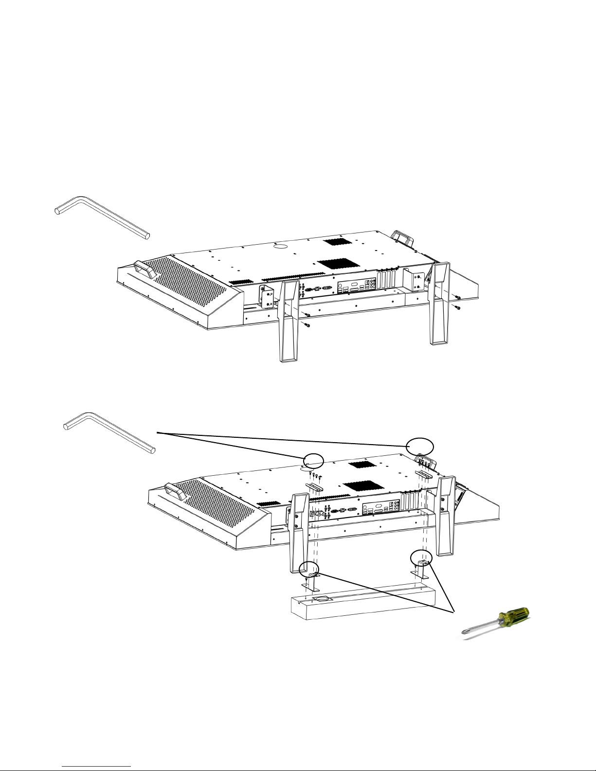
Place the Collaborate Console face-down on a flat, clean, soft, non-abrasive surface as 1.
shown below and attach the feet brackets to the console, then attach the feet to the brackets
as shown.
5 mm
Review port locations on page 2 and make the appropriate cable connections.2.
3 mm
While the unit is still face-down connect the soundbar cables. (See port locations on page 3.
2.) Then install the Collaborate Soundbar using the Short Soundbar Mounting Brackets the
and the screws provided and those on the soundbar as shown. The unit may need to be
repositioned to provide adequate room for mounting the soundbar.
In s t a l l a t I o n Gu I d e 3
Page 6
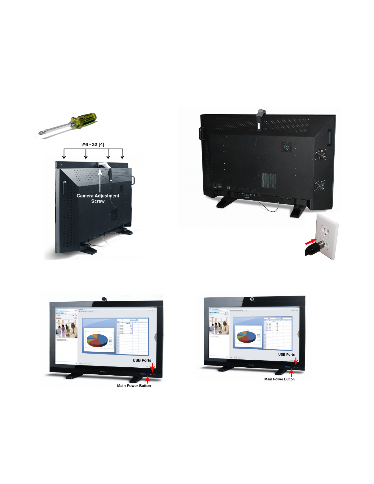
4. Carefully stand the Collaborate Console upright then plug the Wireless Keyboard/Mouse
receiver into one of the USB ports.
5. Clip the camera to the top of the Console then plug the camera into one of the USB ports
located along the bottom of the Console and position it for best results. Open camera lens
cover by turning ring.
NOTE: » If mounting the camera with the optional Camera Bezel, use the four #6-32
screws provided with the Camera Bezel kit to mount the bezel. Attach the Collaborate
Camera as shown.
* Product shown with optional
Camera Bezel installed.
6. Plug the Collaborate into an electrical outlet.
7. Press the power button located on the front of the Console to turn the unit on.
* Product shown with optional Camera Bezel installed.
8. After boot-up has completed, configure the software (See the Software Overview section.)
9. Adjust the camera using the camera adjustment screw as necessary. If using the optional
Camera Bezel, adjust the camera within the bezel.
10. Position the speaker if not mounted to the speaker bracket.
4 te c h n I c a l su p p o r t : 800.283.5936
Page 7
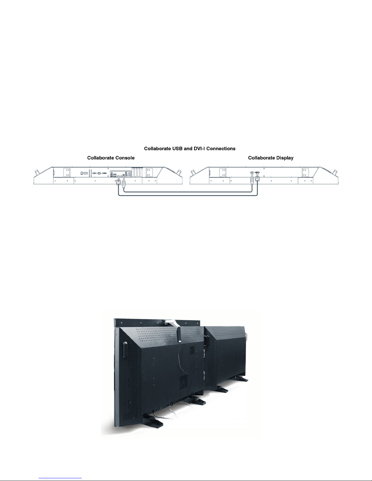
Fo o t st a n d as s e m B l y (du a l mo n I t o r )
CAUTION : The feet are installed with the monitors face-down. Make sure the face
of both monitors rest on a soft, non-abrasive surface to prevent any damage to the
monitor screens. Also, due to the weight of the monitor, make sure a team of two or
more people are available when moving the desktop monitor to prevent personal
injury or damage to the product.
Follow the procedures for attaching the feet for the Console and Display as described on 1.
page 3, step 1.
Review the port locations on page 2 and make the appropriate cable connections as well as 2.
the DVI-I and USB cables shown below.
While the two monitors are still face-down, install the Collaborate Soundbar as described on 3.
page 3, step 3. With a dual system, the soundbar can be mounted to either the Console or
Display or can be placed on the table for positioning as needed.
Carefully stand the two monitors upright then plug the Wireless Keyboard and Mouse 4.
receiver into a PC USB port.
Clip the camera to the top of the Console then plug the camera into a USB port located 5.
along the bottom of the Collaborate Console as shown below. Open camera lens cover by
turning ring.
*Console shown with optional Camera Bezel.
In s t a l l a t I o n Gu I d e 5
Page 8
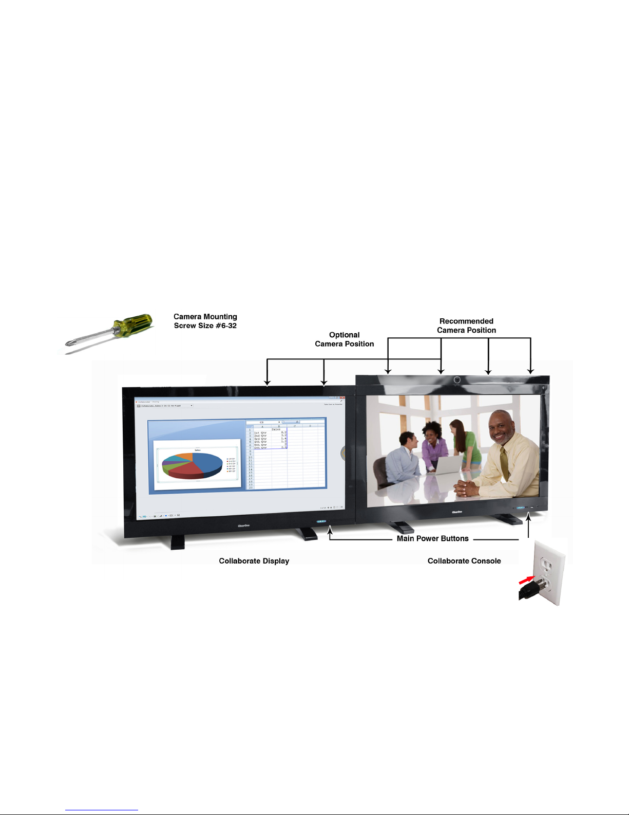
OPTIONAL HD USB CAMERA BEZEL MOUNTING NOTE : There are two methods
for mounting the HD Camera on a dual monitor Foot Stand system using the Camera
Bezel accessory kit.
The Recommended Method provides a more natural conferencing experience with
the participants appearing to address each other as in a face-to-face discussion.
Position the camera so that it is centered over the Primary (Conferencing) Monitor.
Mount the Camera Bezel using the four #6-32 screws provided with the bezel kit.
The Optional Method may make the participants appear to look away from each
other due to the location of the camera. Position the camera so that it is centered
between the Primary (Conferencing) and Secondary (Data Sharing) Monitors. Mount
the Camera Bezel using the four #6-32 screws provided with the bezel kit.. .
NOTE : If using the Optional Method to mount the Camera Bezel, the surface
must be flat and level in order to properly align and install the Camera Bezel.
6. Plug the Collaborate Console and Display monitors into an electrical outlet.
7. Press the power buttons on the front of the Console and Display to turn the units on.
8. After boot-up has completed, configure the software if necessary (See the Software
Installation section.)
9. Adjust the camera using the camera adjustment screw as necessary. If using the optional
Camera Bezel, adjust the camera within the bezel.
10. Position the speaker if not mounted to the speaker bracket.
6 te c h n I c a l su p p o r t : 800.283.5936
*Console shown with optional Camera Bezel.
Page 9
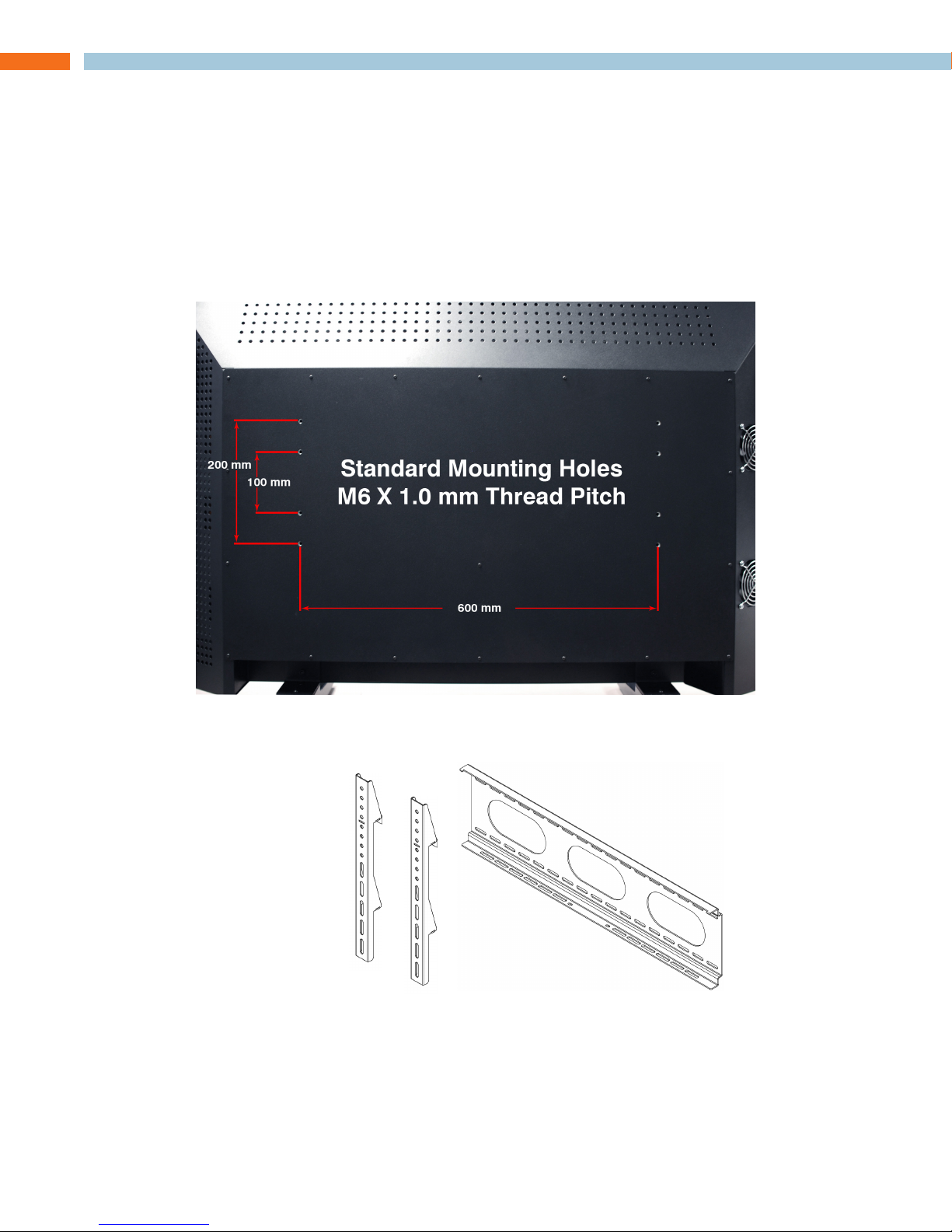
WALL-MOUNT ASSEMBLY OVERVIEW
The Collaborate monitor provides standard mounting sizes (M6 600 x 200 external, M6 600 x 100
internal) and locations for the mounting of the Collaborate monitor onto a wall. As always, comply
with the appropriate mounting recommendations and ensure the wall is capable of handling a
minimum monitor wall mount installation weight of 100 lb.
CAUTION : The Console weighs about 100 lb. Please take all necessary precautions
when lifting. ClearOne recommends only lifting and moving the Collaborate unit with
a team of two or more people.
Wa l l -mo u n t KI t
See Wall Mount instructions provided with the kit for details on installation requirements.
Wall Bracket attaches to wall through
studs or using anchors.
Two TV Brackets attach to the
back of the TV, then they are
hung on the Wall Bracket and
fastened.
NOTE: » ClearOne accepts no responsibility for damage due to improper mounting of
the Collaborate system. It is the responsibility of the installer to ensure the integrity
of the mounting location and the capability of the mounting location to safely handle
the weight of each Collaborate monitor.
In s t a l l a t I o n Gu I d e 7
Page 10
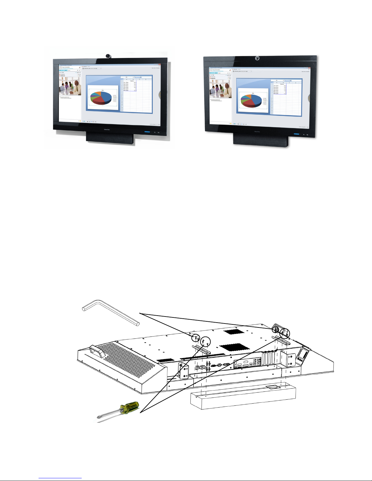
Wa l l -mo u n t as s e m B l y (sI n G l e mo n I t o r )
Install the TV Wall Mount Kit as specified by the manufacturers documentation onto the 1.
intended wall location.
Place the Collaborate Console face-down on a flat, clean, soft, non-abrasive surface and 2.
attach the Collaborate Wall Mount Bracket onto the appropriate mounting holes on the back
of the Collaborate unit (Refer to the manufacturers TV Wall Mount Kit documentation for
appropriate bracket hole locations.)
*Product shown with optional Camera Bezel.
Review port locations on page 2 and make the appropriate cable connections keeping in 3.
mind that some connections may need to be completed after the unit is mounted to the
wall.
While the unit is still face-down, install the Collaborate Soundbar as shown below using the 4.
Long Soundbar Mounting Bracket with the screws provided and those on the soundbar
as shown. Then connect the soundbar cables (See Collaborate port locations for speaker
cable connections on page 2 of this manual.) The unit may need to be repositioned to provide adequate room for mounting the soundbar.
3 mm
8 te c h n I c a l su p p o r t : 800.283.5936
Page 11
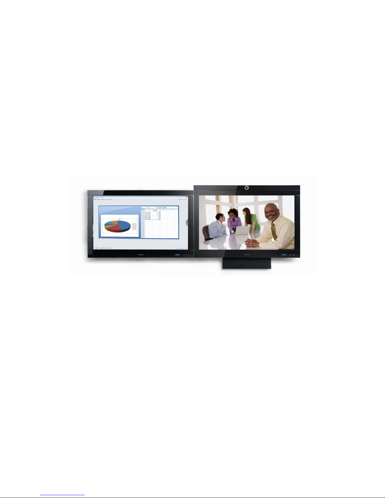
Clip the camera to the top of the Console then plug the camera into one of the USB ports 5.
located along the bottom of the Console.
NOTE: » If mounting the camera with the optional Camera Bezel, use the four #6-32
screws that come with the bezel kit to mount the bezel as shown above. Connect the
Collaborate Camera as shown on page 4. If using the optional Camera Bezel, adjust
the camera within the bezel.
Mount the Collaborate Console onto the TV Wall Mount bracket (See TV Wall Mount 6.
manufacturers instructions.)
Plug the power cable into an outlet.7.
Press the Collaborate Console power switch located on the front to turn the unit on.8.
Once the system has completed bootup, configure the Collaborate Software if necessary.9.
Adjust the camera using the camera adjustment screw as necessary.10.
*Product shown with optional Camera Bezel.
Wa l l -mo u n t as s e m B l y (du a l mo n I t o r )
Install the two TV Wall Mount Kits as specified by the manufacturers’ documentation onto 1.
the intended wall location.
IMPORTANT : Space the brackets appropriately to ensure the desired distance
between the two monitors is achieved. Cable length should also be considered prior
to installing the wall mount brackets.
Place the Collaborate Console and Display face-down on a flat, clean, soft, non-abrasive 2.
surface and attach the Collaborate Wall Mount Brackets onto the appropriate mounting
holes on the back of each Collaborate unit (Refer to the manufacturers TV Wall Mount Kit
documentation for appropriate bracket hole locations.)
Review the port locations on page 2 and make the appropriate cable connections. Keep 3.
in mind that most cable connections may need to be completed after the two units are
mounted to the wall.
In s t a l l a t I o n Gu I d e 9
Page 12
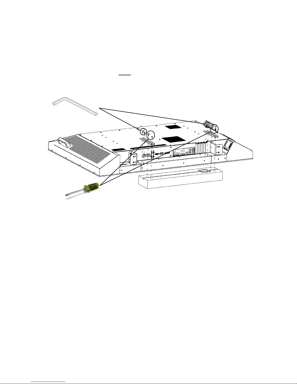
If installing the Collaborate Soundbar to the Collaborate Console, first install the cables, then 4.
install the soundbar using the Long Soundbar Mounting Bracket and the screws provided
and those on the soundbar. (See Collaborate port locations for speaker cable connections
on page 2 of this manual.)
If installing the soundbar to the Display, mount the soundbar using the Long Soundbar
Mounting Bracket and the screws provided and those on the soundbar to the Display but
connect the soundbar cables after the two units are mounted to the wall.
The unit may need to be repositioned to provide adequate room for mounting the
soundbar.
3 mm
Clip the camera to the top of the Console then plug the camera into one of the USB ports 5.
located along the bottom of the Console. See page 6 of this manual for additional HD
Camera mounting options using the optional Camera Bezel.
Mount the Collaborate Console and Display units onto the TV Wall Mount brackets (See TV 6.
Wall Mount manufacturers instructions.)
Plug the power cables into an outlet.7.
Press the Collaborate main power switch located on the front of the Collaborate Console 8.
and Display to turn the units on.
Once the system has completed bootup, configure the Collaborate Software if necessary.9.
Adjust the camera using the camera adjustment screw as necessary.10.
10 te c h n I c a l su p p o r t : 800.283.5936
Page 13
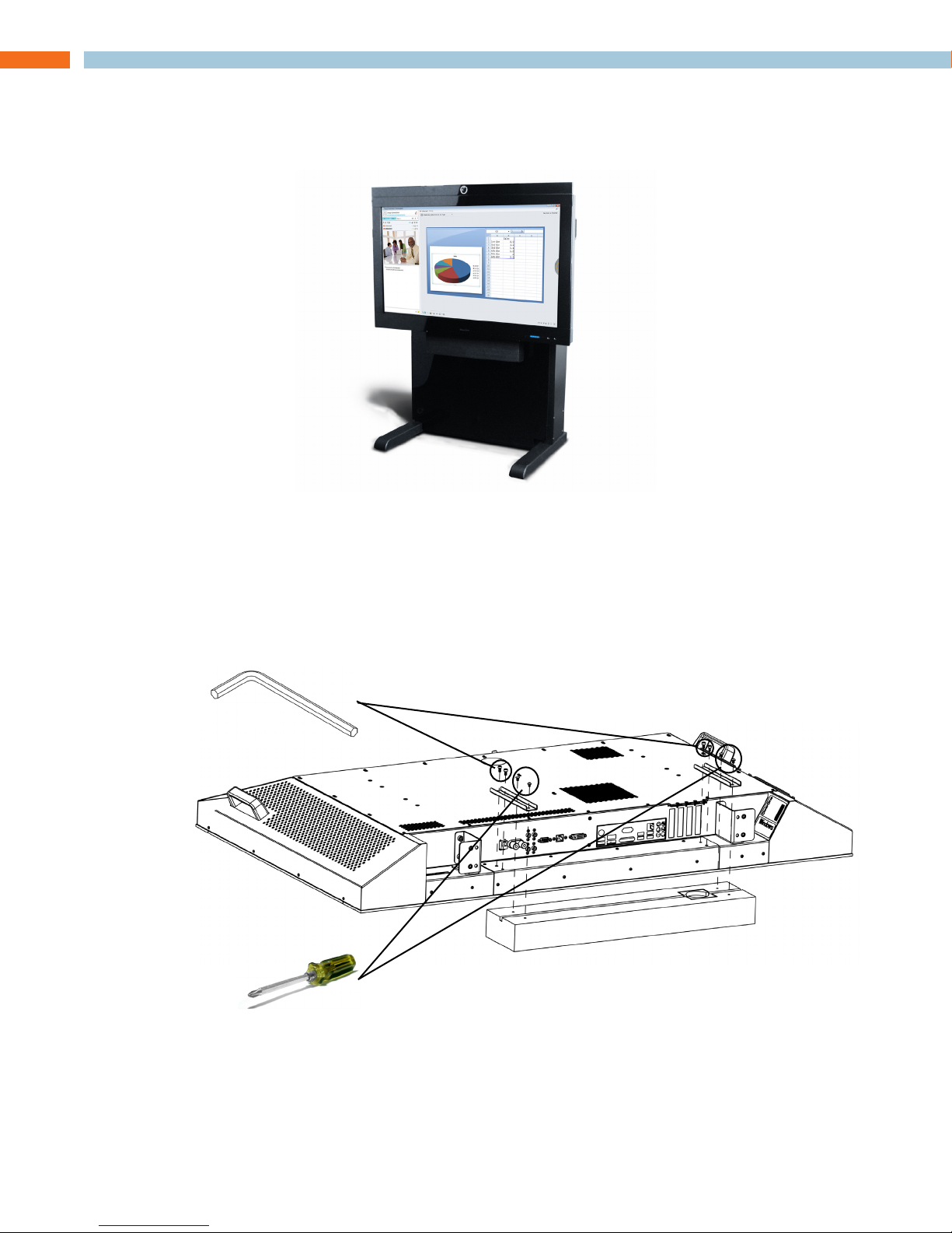
MEDIA STAND ASSEMBLY OVERVIEW
Refer to Collaborate Media Stand Assembly Guide for detailed information on assembling the
Collaborate Media Stand and mounting the Collaborate Console onto it.
*Product shown with optional Camera Bezel.
so u n d B a r In s t a l l a t I o n
Using the Long Soundbar Mounting Bracket, follow the mounting instructions for installing the
ClearOne Soundbar in the Single Foot Stand Assembly section of this manual for mounting the
ClearOne Soundbar to the Collaborate Media Stand.
For installing the monitor onto the Media stand it is recommended to mount the bracket and speaker first, then attach the speaker wires for the Collaborate Console before installing the monitor onto
the Media stand.
3 mm
hd ca m e r a In s t a l l a t I o n
Follow the mounting instructions for installing the HD Camera in the Single Foot Stand Assembly
section of this manual for mounting the camera onto the Collaborate Media Stand.
In s t a l l a t I o n Gu I d e 11
Page 14

12 te c h n I c a l su p p o r t : 800.283.5936
Page 15
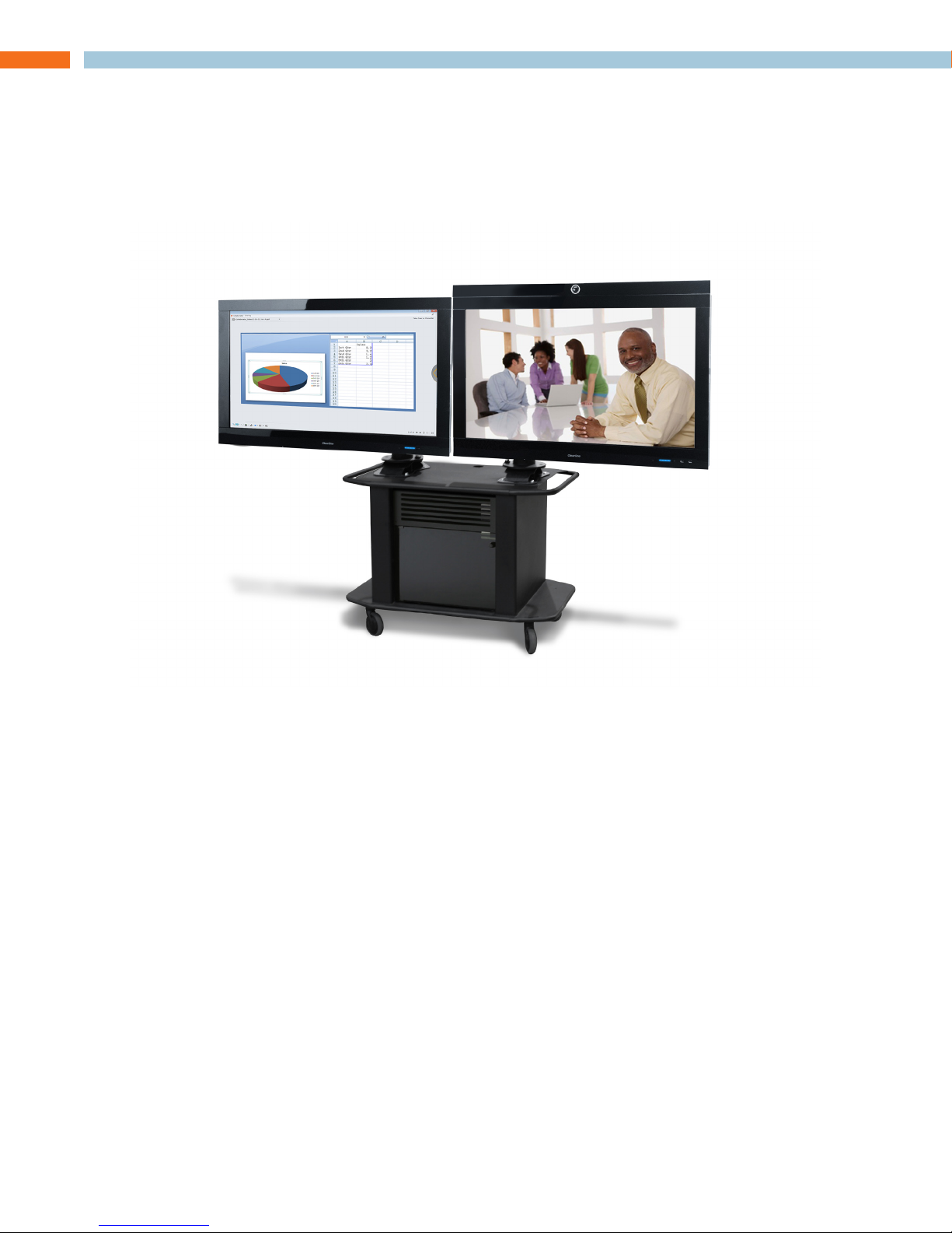
TITAN DUAL ARTICULATING ARM ASSEMBLY OVERVIEW
Follow the instructions that came with the Titan Dual Articulating Arm Cart assembly instructions
for mounting the Collaborate Console and Display units onto the Titan Articulating Arm mounting
brackets.
Connect all required cabling as outlined on page 2 and 3 of this manual.
so u n d B a r In s t a l l a t I o n
The soundbar can be mounted at the bottom of the Collaborate Consle with provided brackets, or
placed on top of the Titan base.
hd ca m e r a In s t a l l a t I o n
Plug the HD Camera into one of the USB ports located along the bottom of the Collaborate Console, then place the camera.
NOTE: » The HD Camera can be mounted onto the Collaborate Console (Conferencing)
monitor using the optional Camera Bezel. This secures the camera while allowing
vertical adjustment.
In s t a l l a t I o n Gu I d e 13
Page 16

14 te c h n I c a l su p p o r t : 800.283.5936
Page 17
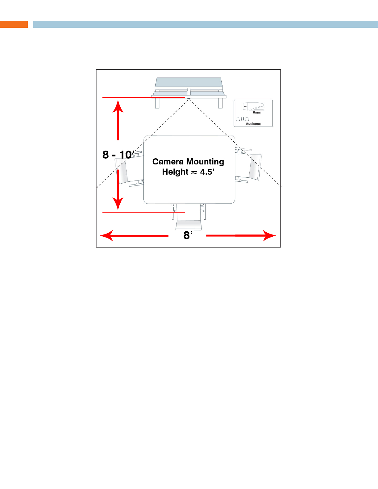
HD CAMERA TOPOLOGY
5.5 mm hd ca m e r a
In s t a l l a t I o n Gu I d e 15
Page 18
SOFTWARE INSTALLATION
The Collaborate system, as delivered, is pre-loaded with the Windows 7 Operating System installation files, and software for installing and configuring Collaborate. An On-line Help System is included with operating instructions.
In s t a l l I n G t h e os
The Collaborate Console as delivered contains a new MS Windows 7 operating system that needs
to be installed and configured. This installation process initiates with the first power-up of the Collaborate Console.
Be prepared to enter the Windows 7 License Key which is printed on a sticker on the »
back of the Collaborate Console unit and also provided in the Windows 7 CD case.
In s t a l l I n G co l l a B o r a t e co n s o l e
The Collaborate Console software installation must be run under the Windows 7 Administrator’s
account. Login to the Collaborate PC as Administrator. (It is recommended to log out of all other
accounts on the PC prior to software installation.)
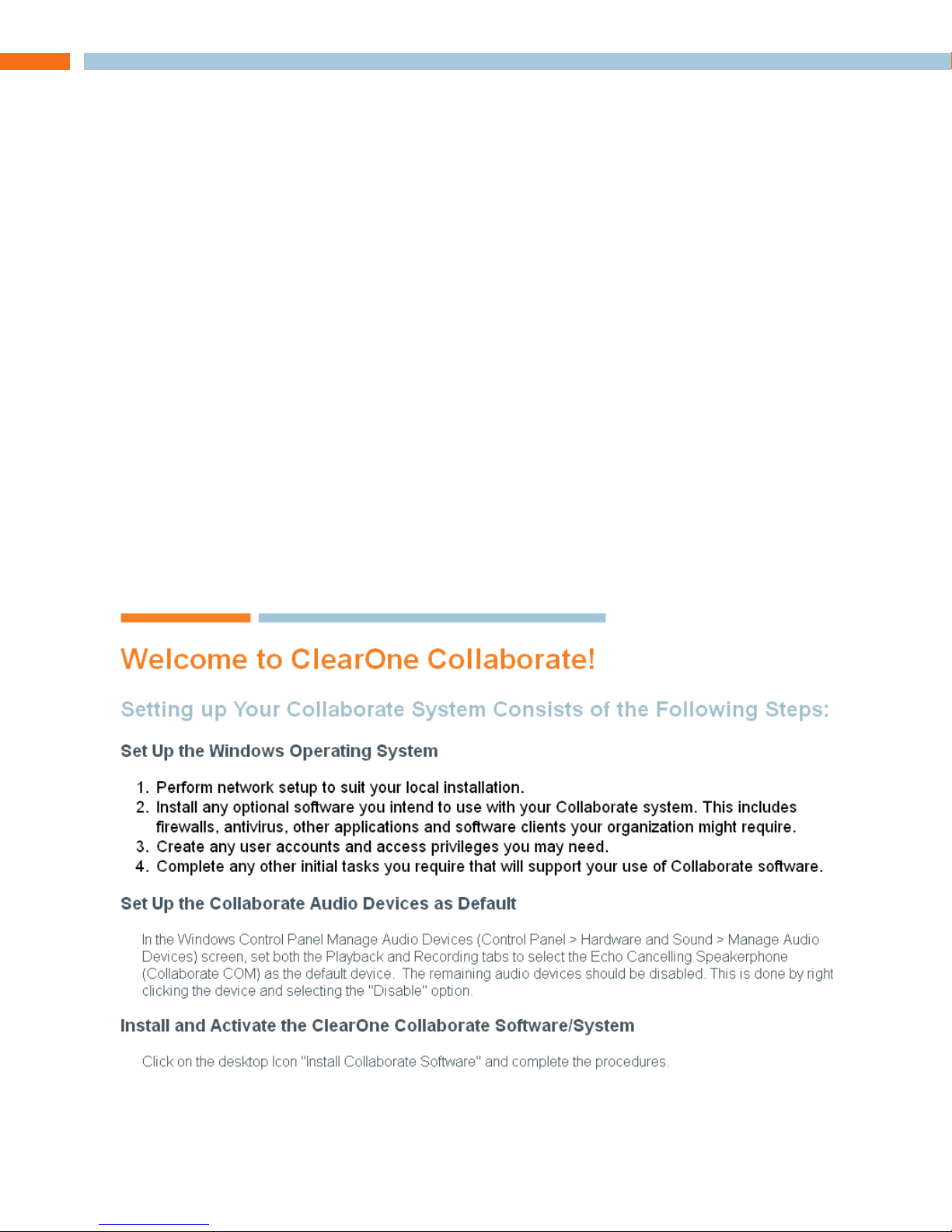
When the system is first booted after the OS is installed it will contain a shortcut to a “Welcome to
ClearOne Collaborate” readme file.
Open this file by double-clicking to find the basic steps needed to prepare the system for your
network and to load your Collaborate Console software and configure devices for use by Collaborate.
This file contains the following:
After completing these steps you may start the Collaborate Console software by clicking on the
Start Collaborate Software icon.
16 te c h n I c a l su p p o r t : 800.283.5936
Page 19

COMPLIANCE
FCC Part 15/ICES-003 Compliance
This equipment has been tested and found to comply with the limits for a Class A digital device, pursuant to Part 15 of
the FCC rules and Industry Canada ICES-003.
These limits are designed to provide reasonable protection against harmful interference when the equipment is
operated in a commercial environment. This equipment generates, uses, and can radiate radio frequency energy
and, if not installed and used in accordance with the instruction manual, may cause harmful interference to radio
communications.
Operation of this equipment in a residential area is likely to cause harmful interference, in which case the user will be
required to correct the interference at his/her own expense.
This device complies with Part 15 of the FCC Rules. Operation is subject to the following two conditions: (1) this device
may not cause harmful interference, and (2) this device must accept any interference received including interference
that may cause undesired operation.
Changes or modifications not expressly approved by ClearOne Communications could void the user’s authority to
operate the equipment.
FCC Part 68 Compliance
US:FBIMM00BCOLLABRT
Ringer Equivalence Number (REN): 0.0B(ac)
This equipment complies with Part 68 of the FCC Rules Requirements adopted by ACTA . On the mixer unit of this
equipment contains, among other information, a product identifier in the format US:AAAEQ##TXXXX. If requested, this
information must be provided to your telephone company.
The REN is used to determine the number of devices that may be connected to the telephone line. Excessive RENs on
the telephone line may result in the devices not ringing in response to an incoming call. In most, but not all areas, the
sum of the RENs should not exceed five (5.0). To be certain of the number of devices that may be connected to the line,
as determined by the total RENs, contact the telephone company to obtain the maximum RENs for the calling area. The
REN for this product is part of the product identifier that has the format US:AAAEQ##TXXXX. The digits represented
by ## are the REN without a decimal point (e.g. 03 is a REN of 0.3).
If this equipment causes harm to the telephone network, the telephone company will notify you in advance that
temporary discontinuance of service may be required. But if advance notice isn’t practical, the telephone company will
notify the customer as soon as possible. Also, you will be advised of your right to file a complaint with the FCC if you
believe it is necessary.
The telephone company may make changes in its facilities, equipment, operations, or procedures that could affect
the operation of the equipment. If this happens, the telephone company will provide advance notice in order for you to
make the necessary modifications to maintain uninterrupted service.
This equipment uses an RJ11C jack that is used to connect this equipment to the premises wiring and telephone
network. This RJ11C jack complies with the applicable FCC Part 68 Rules and Requirements adopted by the ACTA.
A compliant telephone cord and modular plug is provided with this product. It is designed to be connected to a
compatible modular jack that is also compliant. See installation instructions for details.
WARNING: The country code must be set correctly in Console to ensure that the unit operates properly when connected
to the telco network, and that it complies with the country’s telco requirements.
Changing this code to a country other than the intended country of operation might cause Collaborate devices to be
non-compliant.
If you experience problems with this equipment, contact ClearOne Communications, 5225 Wiley Post Way, Suite 500,
Salt Lake City, Utah 84116, or by phone at (800) 945-7730 for repair and warranty information. If the equipment is
causing harm to the telephone network, the telephone company may request you disconnect the equipment until the
problem is resolved.
In s t a l l a t I o n Gu I d e 17
Page 20

No user serviceable parts are contained in this product. If damage or malfunction occurs, contact ClearOne
Communications for instructions on its repair or return.
Connection to party line service is subject to state tariffs. Contact the state public utility commission, public service
commission or corporation commission for information. This equipment cannot be used on telephone company
provided coin service.
If your home has specially wired alarm equipment connected to the telephone line, ensure the installation of this
equipment does not disable your alarm equipment. If you have questions about what will disable alarm equipment,
consult your telephone company or a qualified installer.
Electrical Safety Advisory
This equipment uses AC power which can subjected to electrical surges, typically lightning transients which are very
destructive to customer terminal equipment connected to AC power sources. The warranty for this equipment does
not cover damage caused by electrical surge or lightning transients. To reduce the risk of this equipment becoming
damaged it is suggested that the customer consider installing a surge arrestor.
IC COMPLIANCE
IC: 1970A-COLLABRT
Ringer Equivalence Number (REN): 0.0B(ac)
NOTICE: The term “IC” before the certification/registration number signifies that Industry of Canada technical
specifications were met.
This certification means that the equipment meets certain telecommunications network protective operational and
safety requirements. The Department does not guarantee the equipment will operate to the user’s satisfaction.
The Ringer Equivalence Number (REN) is an indication of the maximum number of devices allowed to be connected
to a telephone interface. The termination of an interface may consist of any combination of devices subject only to
the requirement that the sum of the RENs of all the devices not exceed five. / L’indice d’équivalence de la sonnerie
(IES) sert à indiquer le nombre maximal de terminaux qui peuvent être raccordés à une interface téléphonique. La
terminaison d’une interface peut consister en une combinaison quelconque de dispositifs, à la seule condition que la
somme d’indices d’équivalence de la sonnerie de tous les dispositifs n’excède pas cinq.
The REN is used to determine the number of devices that may be connected to the telephone line. Excessive RENs
on the telephone line may result in the devices not ringing in response to an incoming call. In most, but not all areas,
the sum of the RENs should not exceed five (5.0). To be certain of the number of devices that may be connected to
the line, as determined by the total RENs, contact the telephone company to obtain the maximum RENs for the calling
area. The REN for this product is listed above.
Before installing this equipment, users should ensure that it is permissible to be connected to the facilities of the local
telecommunications company. The equipment must also be installed using an acceptable method of connection. In
some cases, the companies inside wiring associated with a single line individual service may be extended by means
of a certified connector assembly (telephone extension cord). The customer should be aware that compliance with the
above conditions may not prevent degradation of service in some situations.
Repairs to certified equipment should be made by an authorized Canadian maintenance facility designated by ClearOne
Communications. Any repairs or alterations made by the user to this equipment, or equipment malfunctions, may give
the telecommunications company cause to request the user to disconnect the equipment.
Users should ensure for their own protection that the electrical ground connections of the power utility, telephone
lines and internal metallic water pipe system, if present, are connected together. This precaution may be particularly
important in rural areas.
This product meets the applicable Industry Canada technical specifications. / Le présent matériel est conforme aux
specifications techniques applicables d’Industrie Canada.
18 te c h n I c a l su p p o r t : 800.283.5936
Page 21

SPECIFICATIONS
co n n e c t I o n s
RS-232 Control Port
DB9 Female
USB Type: A-type Female Connector, 2.0
Compatible
8 Total Ports:
Two (2) - Front Accessible•
Six (6) - Rear Accessible•
LAN: 10/100/1000 Mb RJ45 Ethernet
Secondary Monitor Output: VGA
co n t r o l ma n a G e m e n t
Collaborate System Control Software
Collaborate Audio Mixer Console
co l l a B o r a t e au d I o mI x e r
Frequency Response
20 Hz - 16 kHz ± 1 dB
Dynamic Range
100 dB (A-Weighted)
THD+N < 0.08%
Processing
AEC, NC, AGC, Gating, NOM
Line Inputs
Two (2) Unbalanced RCA
Line Outputs
Two (2) Unbalanced RCA
Amplifier Outputs
5Winto4Ω(4ΩStable)
Connection: Binding Post Terminals
ca m e r a
HD USB
Fixed Lens
720p/30
MJPEG
USB Type A Connector 2.0 Compatible
co l l a B o r a t e mI c po d s
Number: Ships standard with One
(Optional of up to Two)
Coverage: 360º
Connection:
Daisy-chain RJ-45 with CAT5 Cable
Max Monitor-Pod Distance: 75’
Microphone Sensitivity: -45 dBu
co l l a B o r a t e so u n d B a r
HD Audio Operation:
100 Hz - 20 kHz
Channels: Monaural
Sensitivity:
85 dB 1W @ 1 foot (0.30 meter)
Power: 20W
Impedance:4Ω
co l l a B o r a t e dI a l e r (op t I o n a l )
Wired Only
Room Audio Controls
PC
Supports Windows 7 Ultimate 32-bit
AMD Phenom II x4 Quad Core
RAM: 4 Gb
500 Gb Hard Drive
dI s p l a y
46” LCD
1080p Resolution
Energy Controls
Brightness: 450 cd/m2
Contrast Ratio: 4000:1
Viewing Angle (V / H): 178º / 178º
po W e r
100 - 240 VAC, 50/60 Hz
600 W (Maximum)
en v I r o n m e n t a l
Operating Temperature:
32 - 95º F (0 - 35º C)
Operating Time per 24-hour Period:
12 Hours Powered Max
Humidity:
15 - 80%
me c h a n I c a l
Approximate Dimensions
(Primary Monitor)
W: 44.5” (1130.3 mm)
H: 32.0” (812.8 mm)
D: 5.0” (127.0 mm)
46” Console Weight:
@95 lbs. (43 kg)
46” Display Weight:
@85 lbs. (39 kg)
VESA Mounting Holes
M6 1 mm thread pitch
100 mm & 200 mm Vertical
600 mm Horizontal
co m p l I a n c e
EMC:
FCC Part 15 Class A
EMI:
EN55024
EN55022
IEC610000-4-2, 4-3, 4-4, 4-5, 4-6, 4-11
Safety:
IEC60950-1 2nd Edition, CSAA
> CLEARONE LOCATIONS
HEADQUARTERS:
Salt Lake City, UT USA
5225 Wiley Post Way
Suite 500
Salt Lake City, UT 84116
EMEA
Tel: 44 (0) 1189.036.053
e-mail: [email protected]
APAC
Tel: 801.303.3388
e-mail: [email protected]
LATAM
Tel: 801.974.3621
e-mail: [email protected]
Technical Sales
Tel: 800.705.2103
e-mail: [email protected]
Technical Support
Tel: 800.283.5936
e-mail: [email protected]
In s t a l l a t I o n Gu I d e 19
Page 22

Telephone 1.800.283.5936
1.801.974.3760
FAX 1.801.974.3669
co l l a B o r a t e co n F e r e n c I n G so l u t I o n s
In s t a l l a t I o n Gu I d e
cl e a r on e do c u m e n t
800-401-032-01 - Oct. 20, 2011 (Rev. 1.4)
© 2011 ClearOne All rights reserved. No part of this document may be
reproduced in any form or by any means without written permission
from ClearOne. ClearOne reserves specific privileges.
Other product names may be trademarks of their respective owners.
Information in this document is subject to change without notice.
 Loading...