

Page 1
Beamforming Microphone Array Systems
Group Microphone for Professional Conferencing
Wall Mount Installation Guide
Page 2

GETTING STARTED ...........................................................................1
SKUs USED ........................................................................................2
CONNECTIONS .................................................................................3
Powering your Beamforming microPhone array SyStem ........................3
Poe connectionS.................................................................................4
e-BuS & P-Link connectionS .................................................................4
WALL MOUNT INSTALLATION ........................................................6
PartS received.....................................................................................6
tooLS required ....................................................................................7
waLL mounting Procedure ...................................................................7
muting ...............................................................................................15
Table of Contents
Page 3

WALL MOUNT INSTALLATION GUIDE
Wall Mount Installation Guide 1
GETTING STARTED
Congratulations on purchasing your Beamforming Microphone Array
(BFM) product. BFM units feature 24 microphones with beamforming
and adaptive steering technology designed specifically for use with the
CONVERGE® Pro or CONVERGE® Pro 2 systems.
IMPORTANT: The BFM1 only can be used with the first generation
CONVERGE Pro system; likewise, the BFM2 is compatible only with
the CONVERGE Pro 2 system.
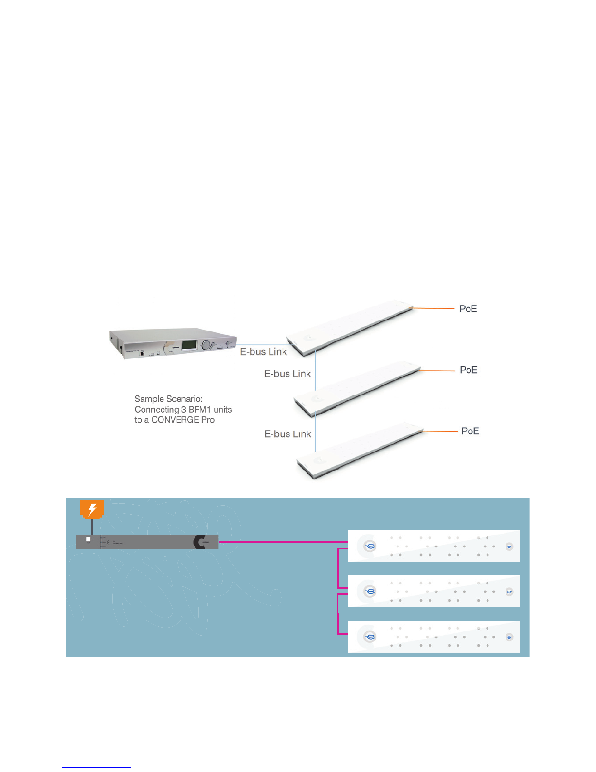
The BFM1 connects with the CONVERGE Pro through an Expansion Bus
(E-bus) port: 3 arrays per supported CONVERGE Pro and up to 16 arrays
can be daisy-chained in the site. The power for the BFM1 is supplied
through a Power-Over-Ethernet (PoE) connection.
IMPORTANT: The Beamforming Microphone Array only can
be used with CONVERGE Pro systems operating at version 4.X
software and firmware.
The BFM2 connects with the CONVERGE Pro 2 through a Peripheral
Link (P-Link) port: 3 arrays per supported CONVERGE Pro 2 and up to 6
BFM2s can be daisy-chained in one P-Link chain. Power for the BFM2 is
supplied through a PoE or P-Link connection from CONVERGE Pro 2.
Instructions for updating CONVERGE Pro or CONVERGE Pro 2 firmware
and BFM firmware are included in the respective BFM Quick-Start Guides
found on the ClearOne website at:
http://www.clearone.com/resources#professional_microphones
Page 4

BEAMFORMING MICROPHONE ARRAY SYSTEMS
2 Beamforming Microphone Array Systems
SKUs USED
The following assemblies or kits may be used in the BFM installation:
• 910-001-003 (white) or 910-001-003-B (black) BFM1
• 910-3200-201 (white) or 910-3200-201-B (black) BFM2
• 910-001-004 PoE Power Supply and Cable Kit for BFM1. Contains
power supply, one AC power cable and two 25-foot CAT5E RJ45
Plenum cables. (One used as the PoE cable and the other as an
E-bus cable). If a PoE kit is not obtained, installers will need to
provide their own PoE unit and all cables.
• 910-3200-202 PoE Power Supply Kit for BFM2. Contains power
supply, one AC power cable and two 25-foot CAT5E or CAT6
RJ45 plenum cables (one used as the PoE cable and the other as
a P-Link cable). If a PoE kit is not obtained, installers will need to
provide their own PoE unit and all cables.
• 910-3200-203-12/24/36/48 (white) or 910-3200-203-12/24/36/48-B
(black) Gen-2 Ceiling Mounting Kit with 12/24/36/48” Suspension
Column
• 910-001-005-12/24/36/48 (white) or 910-001-005-12/24-B (black)
Gen-1 Ceiling Mounting Kit with 12/24/36/48” Suspension Column
NOTE: All above mounting kits are compatible with both the BFM1
and BFM2.
Page 5
PoE
Converge Pro 2
P-Link
(Power, Audio, Control)
200 ft.
P-Link
200 ft.
P-Link
200 ft.
Sample Scenario:
Connecting 3 BFM2 units to one CP2 Unit
WALL MOUNT INSTALLATION GUIDE
Wall Mount Installation Guide 3
CONNECTIONS
This section explains the connections made in BFM installations.
Powering a BFM System
Both the BFM1 and BFM2 can be powered by a standard PoE switch or
a PoE power supply (external or ClearOne; up to three BFM2 units can
be powered by one ClearOne PoE Injector). Additionally, the BFM2 can
be powered via a P-Link from CONVERGE Pro 2 (a single cable carries
power, audio and control).
Converge Pro + Beamforming Mic Array
Converge Pro 2 + Beamforming Mic Array 2
Page 6
BEAMFORMING MICROPHONE ARRAY SYSTEMS
4 Beamforming Microphone Array Systems
P-Link and E-Bus ConnECtions
NOTE: Firmware upgrades are performed via the E-bus or P-Link
connection. Plugging the PoE cable into the E-bus or P-Link
connections may cause damage to your BFM unit.
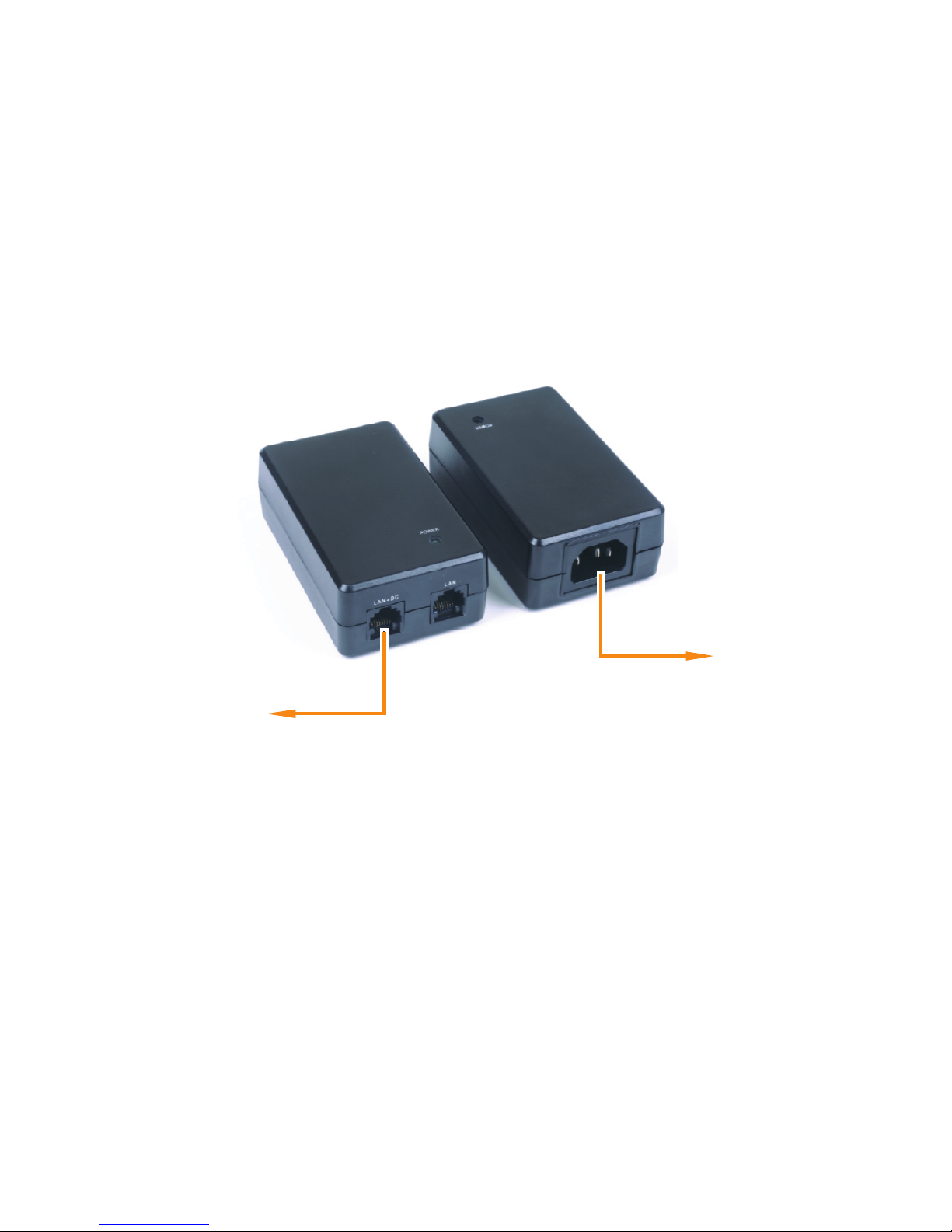
Power Over Ethernet (PoE) Power Supply
(Front and Back Views)
Power Cord
to AC Power
PoE Ethernet Cable to
Beamforming Microphone Array
PoE ConnECtions
Use the appropriate AC cord to connect the PoE power supply to the
AC power. Then plug the PoE cable into the LAN+DC connection on
the power supply. Route the PoE cable where it can be fed through the
mount assembly or to the conference table with the BFM1 or BFM2 unit.
NOTE: The PoE connection is only for power, not control. There
is no daisy-chain power for the BFM1, power must be supplied to
individual units. For the BFM2, power only needs to be supplied
to individual units if not using a ClearOne or same specification
standard PoE Injector.
Page 7

WALL MOUNT INSTALLATION GUIDE
Wall Mount Installation Guide 5
BFM1 units are connected to a CONVERGE Pro stack via LINK IN and
LINK OUT E-bus connections using CAT5E RJ45 cables.
power-source-selection
switch
(USB: for future use)
BFM2 units are connected to a CONVERGE Pro 2 stack via P-Link In and
P-Link Out connections using CAT5E or CAT6 RJ45 cables.
Page 8

BEAMFORMING MICROPHONE ARRAY SYSTEMS
6 Beamforming Microphone Array Systems
The BFM1 is connected to the CONVERGE Pro and to other BFM1
units via the E-bus in the same way multiple CONVERGE Pro units
are connected together. Each unit has a LINK IN and LINK OUT E-bus
connection that allows units to be “chained” together with the LINK OUT
of one unit connecting to the LINK IN of the next unit.
The BFM2 is connected to the CONVERGE Pro 2 and to other BFM2
units similarly, but via the P-Link. Each unit also has a P-Link In and P-Link
Out connection that allows units to be “chained” together with the P-Link
Out of one unit connecting to the P-Link In of the next unit.
Verify all firmware updates, configurations and necessary connections
outlined in the BFM1 or BFM2 Quick-Start Guides and CONVERGE Pro
CONSOLE or CONVERGE Pro 2 CONSOLE online help are made, and
then proceed to the installation of the Wall Mount.
WALL MOUNT INSTALLATION
Parts Received
The following parts are delivered with the Wall Mounting Kit:
A
QTY 4
M3 x 6mm Phillips Pan Head
Requires #1
Phillips Screwdriver Bit
C
QTY 1
Mic Mounting Plate
B
QTY 1
Wall Mounting Plate
Page 9

WALL MOUNT INSTALLATION GUIDE
Wall Mount Installation Guide 7
Verify that you have all the parts required to complete your installation.
When you open the shipping package(s) for the first time, please check
that all items purchased are included. If any of the items (according to
your customer order) are missing or damaged, contact your ClearOne
distributor immediately.
Drywall saw for cutting hole
in wall for cable passage
#1 Phillips
screwdriver
Level used to level the Wall
Mounting Plate
Drill bits
appropriate to
fastener type
Electric or portable drill
Wall fasteners are not provided
and must be appropriate to the
wall material
Tools Required
The following tools may be required for Wall Mount installation of the
Beamforming Microphone Array. You will also need other tools for
installing fasteners (not included in the kit) to hold the Wall Mounting
Plate to the wall where the Beamforming Microphone Array is to be
installed.)
Wall Mounting Procedure
The wall mounted BFM must be placed on a wall facing the intended
conference participants. It can be placed below a video conferencing
system such as COLLABORATE, or in audio-only applications, at eye
Page 10

BEAMFORMING MICROPHONE ARRAY SYSTEMS
8 Beamforming Microphone Array Systems
Studs on
Wall Mounting Plate
Slotted holes in
Mic Mounting
Plate
The Wall Mounting Plate can be mounted to either a solid or hollow wall.
Use fasteners appropriate to the wall type to attach the plate to the wall.
level with the participants. The face of the BFM should be about 8 to 10
feet from the participants.
The Wall Mounting Plate has small studs projecting from the plate that fit
into slotted holes on the Mic Mounting Plate to hold the BFM to the wall.
Page 11

WALL MOUNT INSTALLATION GUIDE
Wall Mount Installation Guide 9
Hollow wall mounting gives the advantage of concealed cable routing.
Locate, level and mark for drill holes and the cable pass-through
cut-out where the Wall Mounting Plate will attach to the wall. Use the
following dimensions for the cable pass-through cut-out for a hollow wall
mounting:
NOTE: Wall mounting MUST be strictly horizontal to assure proper
adaptive steering of audio pickup.
Drill holes to receive the fasteners and cut out the cable pass-through.
NOTE: The anchors and screws used to mount the Wall Mounting
Plate are not provided and must be selected by the installer for the
type of wall material supporting the Wall Mounting Plate. Take care
while drilling and installing the anchors so the wall material does not
tear out and weaken the attachment.
1-1/2"
WALL MOUNT
CUT-OUT
This page can be
used as a template
for the cut-out
1-1/2"
Page 12

BEAMFORMING MICROPHONE ARRAY SYSTEMS
10 Beamforming Microphone Array Systems
Attach the Wall Mounting Plate to the wall with fasteners.
If you have attached the Wall Mounting Plate to a hollow wall, thread
the cables for Link In, Link Out and PoE through the wall space and out
through the hole in the center of the plate.
NOTE: Allow enough extra cable length to pass through the hole to
easily run under the Mic Mounting Plate when it is attached to the
microphone array and to the ends where they are to be connected.
Wall fasteners not included in the kit.
Select fasteners appropriate to wall material.
Page 13

WALL MOUNT INSTALLATION GUIDE
Wall Mount Installation Guide 11
Notice that the Mic Mounting Plate (C) has four holes used for mounting
to the back of the Beamforming Microphone Array. There are three
slotted keyholes big enough for screw heads to pass through and one
hole that is not slotted.
Place the Mic Mounting Plate on the back of the Beamforming
Microphone Array and insert the screws (A) into the Beamforming
Microphone Array corresponding to the holes in the Mic Mounting Plate.
Tighten all screws with the #1 Phillips screwdriver.
C
A 4X
Cable Retention Clips
Install and tighten all screws.
Use #1 Phillips screwdriver bit
to avoid damaging screws.
For mountings with the cables coming through the wall, hold the
Beamforming Microphone Array with the Mic Mounting Plate attached,
route the E-bus and PoE cables under the Mic Mounting Plate to the
ends where they will be connected.
Page 14

BEAMFORMING MICROPHONE ARRAY SYSTEMS
12 Beamforming Microphone Array Systems
Connect the LINK IN, LINK OUT (if needed) and PoE cables and secure
the cables under the Cable Retention Clips.
Use slotted keholes in Mic Mounting Plate
to hang Beamforming Microphone Array
on Ceiling/Wall Mounting Plate
LINK IN and LINK OUT
Connectors
PoE Connector
Pass LINK IN, LINK OUT and PoE
cables through plates and
under Cable Retention Clips
For mountings with the cables coming through the wall, hold the
Beamforming Microphone Array with the Mic Mounting Plate attached,
route the E-bus and PoE cables under the Mic Mounting Plate to the
ends where they will be connected. Connect the LINK IN, LINK OUT
(if needed) and PoE cables and secure the cables under the Cable
Retention Clips.
Page 15

WALL MOUNT INSTALLATION GUIDE
Wall Mount Installation Guide 13
Move the Beamforming Microphone Array forward onto the Wall
Mounting Plate with the studs passing through the slotted keyholes. Then
slide the assembly down slightly to firmly seat the studs into the tops of
the slots. If the cables are outside of the wall, carefully route them to the
mixer to avoid tangling or hazard.
Use slotted keholes in Mic Mounting Plate
to hang Beamforming Microphone Array
on Ceiling/Wall Mounting Plate
LINK IN and LINK OUT
Connectors
PoE Connector
Pass LINK IN, LINK OUT and PoE
cables through plates and
under Cable Retention Clips
Carefully route cables to the
mixer to avoid tangling or hazard.
Page 16

BEAMFORMING MICROPHONE ARRAY SYSTEMS
14 Beamforming Microphone Array Systems
When the Wall mounting of the Beamforming Microphone Array is
completed, use the CONVERGE Console software to configure the array
for the proper pickup pattern.
NOTE: Wall mounting MUST be strictly horizontal and with the “C”
logo on the left-hand side to assure proper adaptive steering of
audio pickup.
Front View of Mic Mounting Plate over Wall Mounting Plate
(Beamforming Microphone Array and cables not shown)
Wall Mounting Plate stud through
slotted keyhole in Mic Mounting Plate
Page 17

WALL MOUNT INSTALLATION GUIDE
Wall Mount Installation Guide 15
Muting
On the wall, the Mute On/Off buttons are available for use when
conferencing. When the microphone array is active, the microphone
icons in the buttons illuminate blue. If either button is pressed, the
Beamforming Microphone Array mutes and the buttons illuminate red. If
pressed again, the array un-mutes and is active again.
Page 18

BEAMFORMING MICROPHONE ARRAY SYSTEMS
16 Beamforming Microphone Array Systems
© 2016 ClearOne, Inc. All rights reserved.
Information in this document is subject to change without notice. DOC-0139-001 Revision 2.2 SEPTEMBER 2016
CLEARONE CONTACTS
HEADQUARTERS:
Salt Lake City, UT USA
5225 Wiley Post Way
Suite 500
Salt Lake City, UT 84116
Tel: +801.975.7200
Toll Free: +800.945.7730
Sales: +800.707.6994
Fax: +801.303.5711
e-mail: sales@clearone.com
Tech Support:
Tel: +800.283.5936
e-mail: tech.support@clearone.com
Europe:
Tel: +44.1454.616.977
e-mail: global@clearone.com
Asia Pacific:
Tel: +91.9930782195
e-mail: global@clearone.com
Middle East:
Tel: +91.9930782195
e-mail: global@clearone.com
 Loading...