

C
C
X
X--
o
o
n
n
e
e
CLEARjet Printer
User Manual
V1.4
© CLEARjet GmbH 2004

CLEARjet GmbH CX-one
CX-one User Manual
Last Edition: June 2004 Copyright CLEARjet GmbH 2004
Editor: Zirl
All rights reserved. No part of this publication may be reproduced, stored in a retrieval system, or transmitted, in any
form or by any means, electronic, mechanical, photocopying, recording, translation or otherwise, without prior
permission in writing.
Liability Statement
This CLEARjet product has been built in accordance with the ISO 9001standard. CLEARjet GmbH makes no claims
regarding this product, its commercial quality or its suitability for any particular task.
Please note and heed the WARNING and CAUTION labels that have been placed on the equipment for your safety.
Please do not attempt to operate or repair this equipment without adequate training. Any use, operation or repair in
contravention of this document is at your own risk. By acceptance of this system you hereby assume all liability
consequent to your use or misuse of this equipment. CLEARjet GmbH assumes no liability for incidental, special or
consequential damage of any kind. Equipment specifications, applications and options are subject to change at the
sole discretion of CLEARjet GmbH without notice.
Safety
All CLEARjet products are built in accordance with strict safety and reliability specifications. The following basic
safety tips are given to ensure safe installation, operation and maintenance of CLEARjet equipment and are not to be
considered as comprehensive on all matters of safety.
• Connect equipment to a grounded facility power source. Do not defeat or bypass the ground lead.
• Place the equipment on a stable surface (table) and ensure floors in the work area are dry and non-slip.
Insulated rubber floor mats are preferred.
• Know the location of equipment branch circuit interrupters or circuit breakers and how to turn them on and
off in case of emergency.
• Know the location of fire extinguishers and how to use them. ABC type extinguishers may be used on
electrical fires.
• Know local procedures for first aid and emergency assistance at the customer facility.
• Use adequate lighting at the equipment location.
• Maintain the recommended temperature and humidity ranges at the equipment location.
• Use proper lifting techniques when moving or installing the equipment.
• Use standard electrostatic discharge (ESD) precautions when working on or near electrical circuits.
• Do not defeat or disconnect safety interlocks on covers. Operate the printer with the cover closed.
Conformity Regulations
This equipment generates, uses, and can radiate radio frequency energy. If it is not installed and used in accordance
with this instruction manual, it may interfere with radio communications. We confirm that the CX-one complies with
the requirements of the EM Directive 89/336/EEC. This equipment has been tested and found to be within the limits
for Class A, pursuant to norm EN55022. This product is equipped with reasonable protection against radio
interference. Operation of this equipment may possibly cause interference. In the event of interference, the user, at
their own expense, will be required to take whatever measures are necessary to correct the problem.
Notice to Users of Printers Equipped with a Contactless Smart Card Coupler
The contactless smart card coupler emits radio-frequency waves and must be used as installed and recommended
by CLEARjet. You may not modify the coupler or how it is used without the written permission of CLEARjet. You may
not operate the printer after modifying the coupler or its method of operation.
Trademarks
• Microsoft, Windows, Windows NT are trademarks or registered trademarks of Microsoft Corporation.
• CLEARjet is a trademark or registered trademark of CLEARjet GmbH, Grambach, Austria.
• All other trademarks are the property of their respective owners.
CLEARjet GmbH
http://www.clearjet.com
info@clearjet.com
Schloss Spielerhof
Hauptstrasse 12
A-8071 Grambach / AUSTRIA
User Manual page 2 / 40

CLEARjet GmbH CX-one
CONTENTS
1 GENERAL INFORMATION .................................................................................................................. 5
1.1 Contents of package...................................................................................................................... 5
1.2 Introduction .................................................................................................................................... 6
1.3 Functionality................................................................................................................................... 7
1.4 Applications.................................................................................................................................... 8
1.5 Product Descriptions...................................................................................................................... 9
1.6 Compatible Card Systems........................................................................................................... 12
1.7 Type Styles .................................................................................................................................. 13
2 TECHNICAL INFORMATION............................................................................................................. 14
2.1 Specifications............................................................................................................................... 14
2.2 Environment................................................................................................................................. 14
2.3 Dimensions .................................................................................................................................. 15
2.4 Power Source and Consumption................................................................................................. 16
2.5 Interfaces ..................................................................................................................................... 16
2.6 Print Head.................................................................................................................................... 17
2.6.1 Print Head DK 200 – 1.......................................................................................................... 17
2.6.2 Print Head DK 300 – 1.......................................................................................................... 17
2.7 Printing Area ................................................................................................................................ 18
2.8 Card Design................................................................................................................................. 19
3 MAINTENANCE AND SERVICE........................................................................................................ 20
3.1 Introduction .................................................................................................................................. 20
3.2 Maintenance Intervals.................................................................................................................. 20
3.3 Self-cleaning Mode ...................................................................................................................... 21
3.3.1 CLEARjet Cleaning Card...................................................................................................... 21
3.4 Cleaning of the Housing............................................................................................................... 22
3.5 Consumables – Expected Lifespan ............................................................................................. 23
3.5.1 Lifespan: Print Head DK 200 – 1.......................................................................................... 23
3.5.2 Lifespan: Erase Roller ..........................................................................................................23
3.5.3 Lifespan: Printer Mechanism................................................................................................ 24
3.6 Replacing Consumables.............................................................................................................. 25
3.6.1 Replacing the Print Head...................................................................................................... 25
3.6.2 Replacing the Erase Module................................................................................................. 26
4 PRINTER CONFIGURATIONS........................................................................................................... 28
4.1 Using the DIP-Switches............................................................................................................... 28
4.2 Adjusting the Print Energy ........................................................................................................... 29
4.3 Adjusting the Erase Energy ......................................................................................................... 29
4.4 Test Mode.................................................................................................................................... 29
4.5 Loading New Firmware................................................................................................................ 29
5 ENCODING MODULES...................................................................................................................... 30
5.1 Magnet Encoding......................................................................................................................... 30
5.1.1 General................................................................................................................................. 30
5.1.2 Available Modules................................................................................................................. 30
5.1.3 Card Specification................................................................................................................. 30
5.1.4 Character Set........................................................................................................................ 31
5.1.5 Controlling the Magnetic Module.......................................................................................... 31
5.2 Contact Chip Encoder.................................................................................................................. 31
5.2.1 General Information.............................................................................................................. 31
5.2.2 Possible Installations............................................................................................................ 32
5.2.3 Controlling the Contact Chip Encoder .................................................................................. 32
5.3 RF Chip Encoding........................................................................................................................ 33
5.3.1 General Information.............................................................................................................. 33
5.3.2 Possible Installations............................................................................................................ 33
5.3.3 Controlling of the RF Chip Encoder...................................................................................... 34
User Manual page 3 / 40

CLEARjet GmbH CX-one
6 BARCODE READER.......................................................................................................................... 35
6.1 General Information ..................................................................................................................... 35
6.2 Reading Area of the Barcode Reader.......................................................................................... 35
6.3 Barcode Specification.................................................................................................................. 35
6.4 Controlling the Barcode Reader................................................................................................... 35
7 DIRECTION DETECTOR.................................................................................................................... 36
7.1 Functionality................................................................................................................................. 36
7.2 Processing ................................................................................................................................... 36
7.3 Card Design................................................................................................................................. 36
7.4 Command Sequence................................................................................................................... 36
7.5 Position of the Direction Marking................................................................................................. 37
7.6 Dimensions .................................................................................................................................. 37
7.7 Optical Parameter........................................................................................................................ 38
7.7.1 Measurement Conditions...................................................................................................... 38
7.7.2 Application Note.................................................................................................................... 38
7.8 Controlling the Direction Detector................................................................................................ 38
8 HOPPER (CARD FEEDER)................................................................................................................ 39
8.1 General Information ..................................................................................................................... 39
8.2 Card Specification........................................................................................................................ 39
8.3 Technical Data............................................................................................................................. 39
8.4 Application Note........................................................................................................................... 39
9 ORDER INFORMATION..................................................................................................................... 40
9.1 CX-one......................................................................................................................................... 40
9.2 CX-one Hopper............................................................................................................................ 40
9.3 Option (Print Head Upgrade)....................................................................................................... 40
9.4 Spare Parts and Accessories....................................................................................................... 40
User Manual page 4 / 40
CLEARjet GmbH CX-one
1 GENERAL INFORMATION
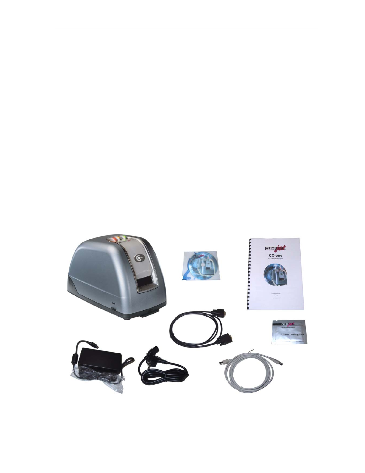
1.1 Contents of package
Please check contents of package before first time installation of CX-one.
Contents:
c 1 x CX-one
d 1 x Power supply
e 1 x Power cord
f* 1 x Serial cable
g 1 x USB cable
h 1 x CX-one CD
i 1 x CX-one User Manual
j 1 x Cleaning Card
* Packages with CX-one models with integrated CHIP or RF chip encoding modules
include two serial cables.
i
h
g
f
j
e d
c
User Manual page 5 / 40
CLEARjet GmbH CX-one
1.2 Introduction
Printing and reprinting smart cards with visible information in top-quality resolution has
been possible for some time, thanks to the CP2 CLEARjet printer.
Now all this is possible at a fraction of the time – thanks to the CX-one, the embodiment
of CLEARjet’s new improved technology. To achieve this high level of performance all
printers in the CX-one range have a USB interface. The unique print/erase unit ensures
outstandingly efficient card throughput.
The technical basis of CLEARjet technology is protected by patents world-wide.
With CLEARjet you can give any card with a rewritable surface an individual look: A
user interface tailor-made to the needs of your application. The user benefits from being
able to see up-to-the minute information. If the data changes, the card is simply erased
and rewritten. The card is always up to date and can be reused several hundred times.
The CX-one can be used in conjunction with most computer systems.
In addition, read/write facilities for chip and magnetic cards can be built into your printer,
so that updating the card, erasing the surface and rewriting are part of the same single
transaction. You also have the option to enhance your system with an automatic card
feeder.
The CX-one is compatible with both ISO cards with a rewritable surface and one-way
tickets with a thermal coating.
This manual includes information on the most important components, basic printer
functions and cleaning and servicing.
For information on printer controlling, software commands, etc. see the Programmers
Manual.
User Manual page 6 / 40
CLEARjet GmbH CX-one
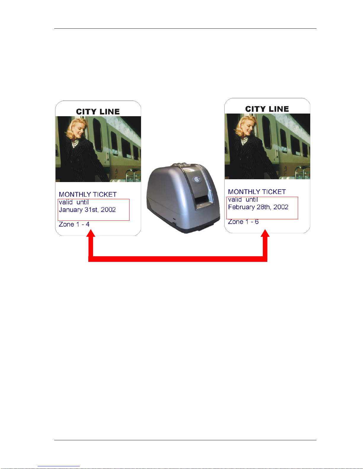
Thermorewrite Cards
The CX-one works with ISO cards which have a thermorewrite (TRW) surface.
Cards of this type can be erased and reprinted several hundred times. The TRW
coating is applied as part of the production process (TRW foil is supplied by CLEARjet
GmbH).
erasing
printing
chip encoding
updated information
As a result the cards can be used to make all kinds of data visible to the cardholder: for
example, up-to-the-minute information, points totals, card validity and advertising
slogans.
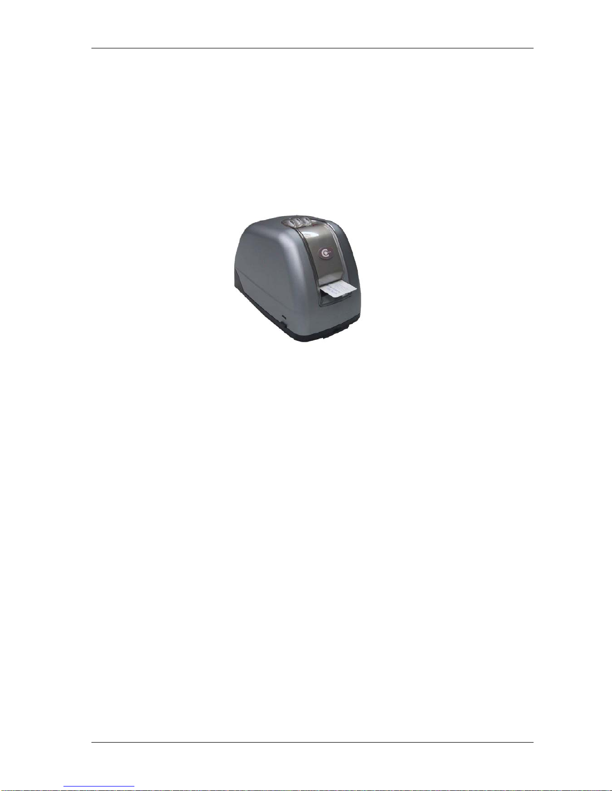
1.3 Functionality
The CX-one allows you to print and erase both cards with a TRW surface and thermodirect tickets. TRW coatings are special materials which change their optical qualities
when subjected to heat. This makes them ideal for card surfaces which need to be
erased and reprinted.
When encoding modules are incorporated into your printer, you can alter and edit visual
information (as well as electronically saved data) in a single transaction.
User Manual page 7 / 40
CLEARjet GmbH CX-one
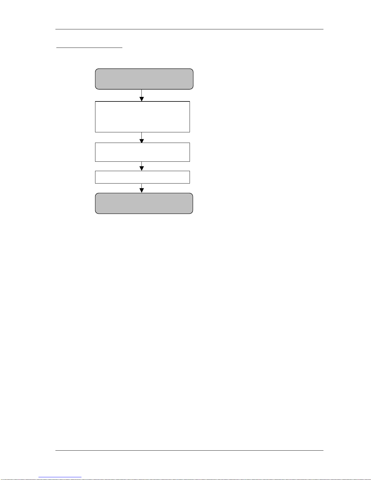
Basic Print Procedure:
Insert card
Read/write
electronic data
(chip, magnetic stripe,...)
Erase old
text/graphics
Print new information
Eject card
1.4 Applications
The CX-one can be used in any situation in which frequently changing information
needs to be made visible to the user, as well as saved electronically to the card.
Possible applications include points cards, customer loyalty cards, membership
cards, visitor passes, travel cards, time cards, etc. You can also use the CX-one to
update advertising information on customer cards over and over again.
The printer is designed for use in an office or similar environment.
Special OEM versions of the printer, without a housing, are available for integration into
other devices (e.g. ticket/card dispensers, info points, etc.).
User Manual page 8 / 40
CLEARjet GmbH CX-one
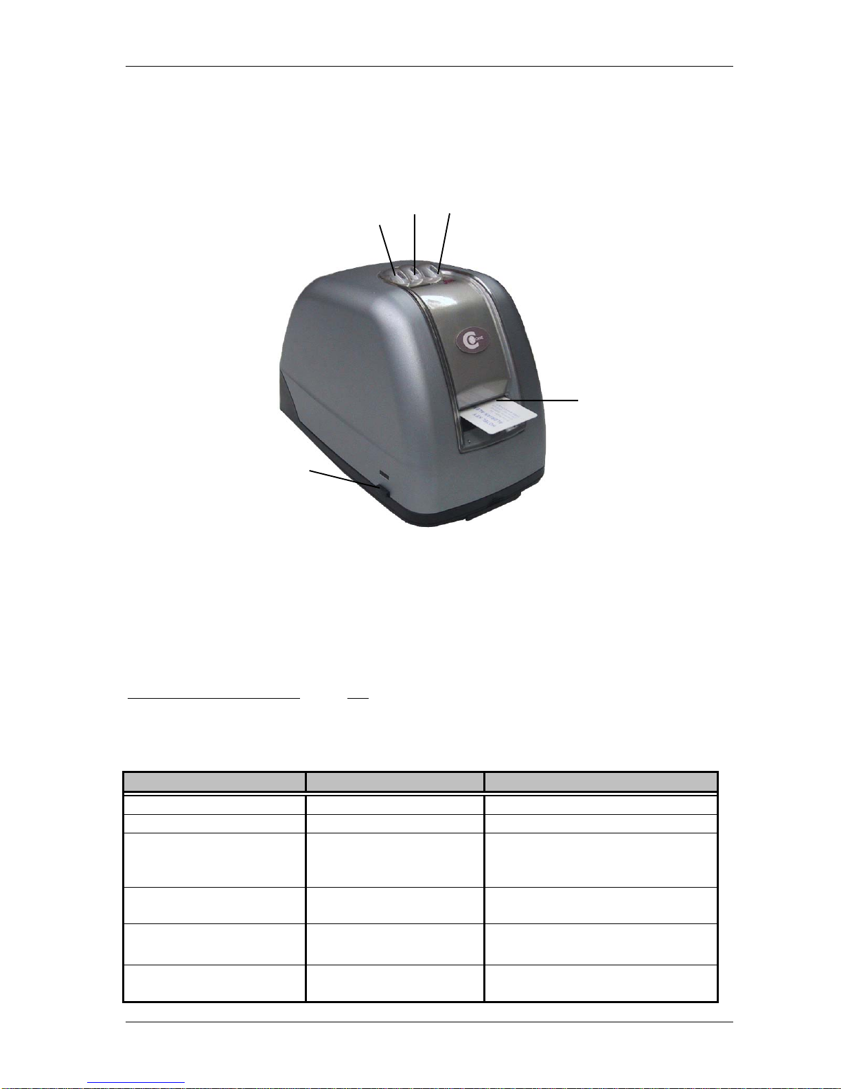
1.5 Product Descriptions
Front View
e
g
f
d
c
1: Red LED
2: Yellow LED
3: Green LED
4: Card slot
5: Housing lock left and right
The card slot is found at the front of the printer (4). The card should be inserted with the
rewritable (TRW) surface
to the top.
On the top of the device are three indicator LEDs (red, yellow and green).
LED SIGNALS:
LED SIGNAL STATUS
green e on The printer is on
red c
yellow d
green e
flashing An error has occurred
yellow d on The printer is waiting for a card
to be inserted
green e flashing The printer is warming up.
You cannot insert a card.
red c + Beep flashing Cleaning of the printer with a
cleaning card is necessary
User Manual page 9 / 40
CLEARjet GmbH CX-one
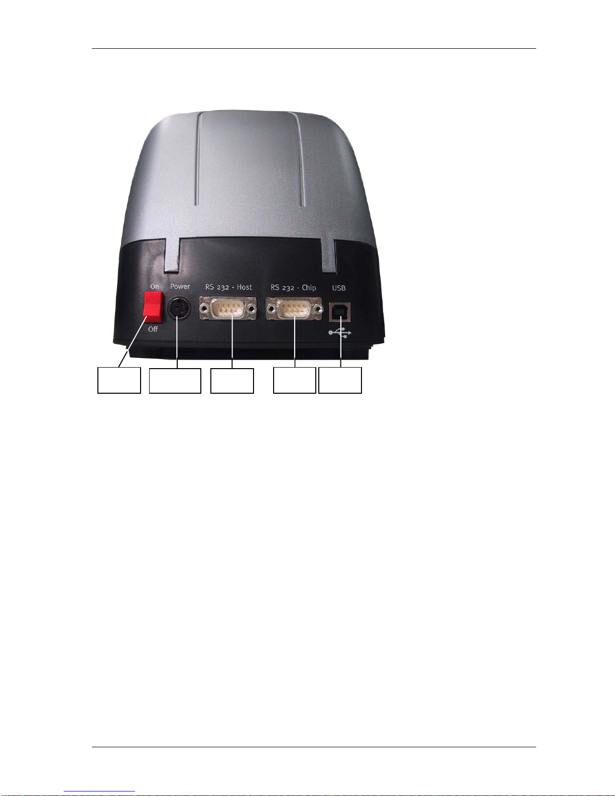
Back View
Host
Power
Su
pply
Chip USB
Power
Switch
The CX-one printer mechanism can be controlled either via a serial interface (RS 232 Host) or a USB interface (USB).
A further serial interface (RS 232 - Chip) is available for connection to a card-read/write
device. This interface gives access to the built-in encoding module (depending on
device configuration).
There is also a power supply socket to connect the external power supply unit and a
power-switch at the back of the printer.
User Manual page 10 / 40
CLEARjet GmbH CX-one
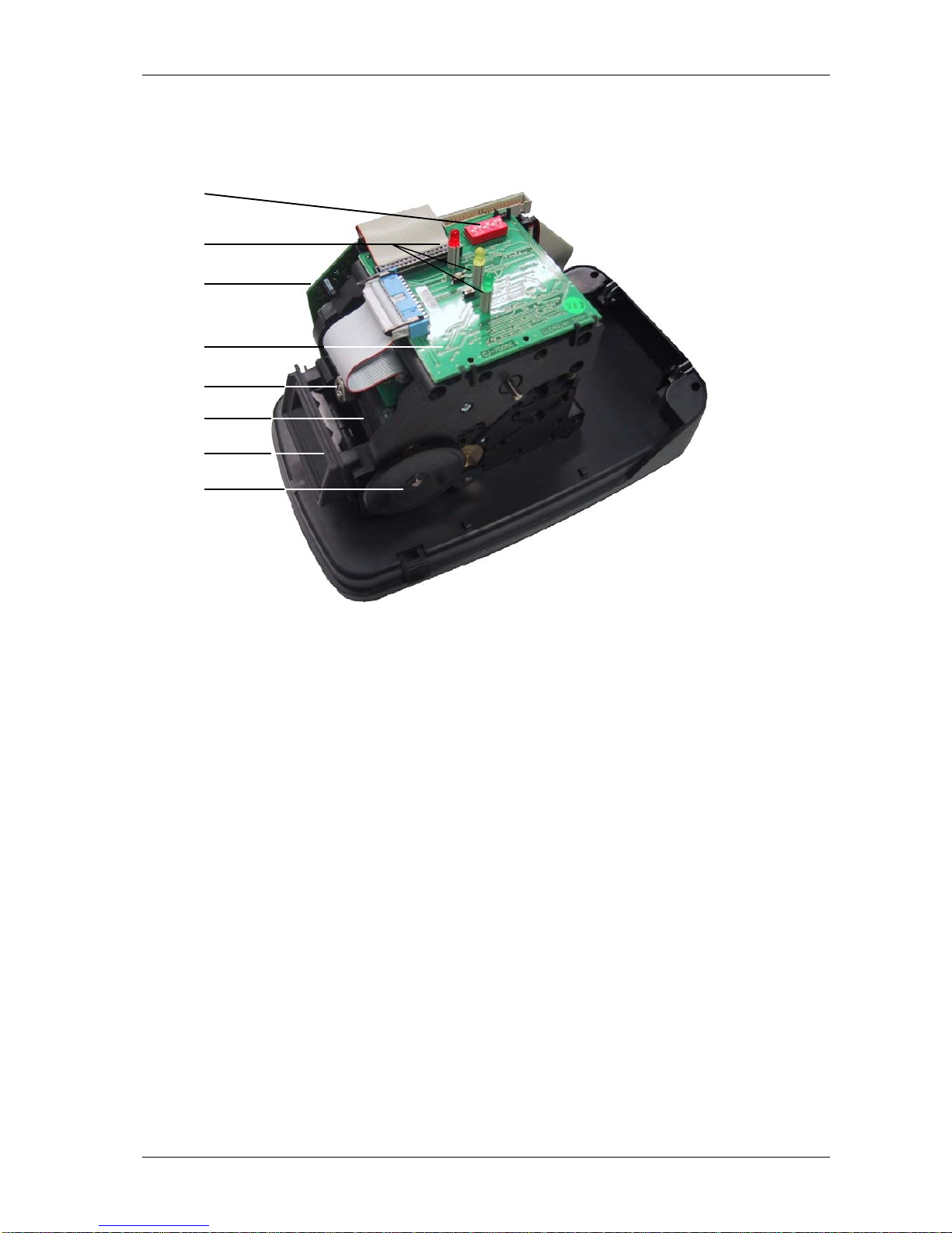
Printer Mechanism
g
i
j
h
e
d
c
f
Function Groups:
1: Rotating print/erase device
2: Central mount for print head
3: Card slot
4: Card transport mechanism (gear wheels)
5: DIP-Switches – to set various printer modes
6: Indicator LEDs
7: Main board
8: Print head-control board with keys for service functions
User Manual page 11 / 40

CLEARjet GmbH CX-one
1.6 Compatible Card Systems
The CX-one can be upgraded with many read/write modules for ISO cards. Magnetic
cards, chip cards or contactless chip cards can not only be printed onto, but
electronically modified as well.
Card specifications regarding size, tolerance, quality and implementation must be
compatible with the relevant ISO standards for chip or magnetic cards.
The printer is compatible with most known TRW materials. However, we cannot
guarantee that the printer will work with any particular card.
As this technology is an emerging one, no specific standards are currently available. It
is for this reason that ISO standards for magnetic and chip cards are used for material
specifications.
The following standards are used to specify the quality of usable cards:
ISO 7810, ISO 7811 parts 1 to 5, ISO 7812, ISO 7813, ISO 7816
Thickness of Cards:
This device is made to process cards with thickness between 0.3 mm and 0.9 mm.
To ensure the quality of the TRW surface, we also recommend the following additional
process:
1. Production of 30 sample cards
2. Order a test-run from CLEARjet
3. Testing and approval of sample cards by CLEARjet
4. Depositing of test cards by the client as a standard for later comparison
5. Agreement between client and card producer that all future cards must be identical
with the sample set (same production parameters, materials, card specifications,
tolerance levels, etc.)
6. Spot checks of card sets on delivery, as well as comparison with sample cards.
Rewritable Materials
The following materials are currently compatible:
Material Type Description
TYPE 1 RICOH TC stripe
TYPE 2 RICOH TC full-surface
TYPE 3 MITSUBISHI LEUCO
TYPE 4 RICOH LEUCO
User Manual page 12 / 40

CLEARjet GmbH CX-one
1.7 Type Styles
The CX-one offers three standard proportional fonts at different sizes, as well as a
graphics mode.
The standard fonts are:
Font 1 ⇒ approx. 3.7 mm height (DK 200-1)
Font 2 ⇒ approx. 2 mm height (DK 200-1)
Font 3 ⇒ approx. 1.5 mm height (DK 200-1)
Please note, this character height is valid for the print head DK 200-1 only.
If you use the print head DK 300-1, smaller characters are obtained due to a different
print-resolution.
By installing a printer driver, various other fonts (depending on the program), as well as
many Windows fonts can be printed.
Print Examples
Print using Windows driver
(graphics mode)
Standard fonts
User Manual page 13 / 40

CLEARjet GmbH CX-one
2 TECHNICAL INFORMATION
2.1 Specifications
• 3 internal standard fonts
• Graphics mode / text mode
• Printing of text and graphics via windows driver
• Max. resolution of 300 x 600 dpi
• Serial interface: 9600 Bd, 38400 Bd or 57600 Bd (switchable)
• USB interface Rev 1.1 (FULL Speed 10 MBaud)
• Rotate the printing area in 90° steps
• Prints cards with thermochromic surface
• Prints thermo-direct tickets
• Integration of many chip card interfaces possible
• Special model for magnetic cards (R/W)
• Special model for barcodes – printing and reading
• Special model with automatic card loading
Transaction Speeds
• Card throughput ⇒ c. 240 mm/sec.
• Erase speed ⇒ c. 60 mm/sec.
• Print speed ⇒ c. 60 mm/sec.
Specific speeds may vary when special materials or applications are used.
• Operating performance: max. 150 cards per hour
2.2 Environment
The device is designed for use in an office or similar environment.
You should position your printer on a sturdy, even surface in a well-ventilated room.
Room temperature should be moderate, with no abrupt temperature changes or
variations in humidity. The CX-one needs to be kept out of direct sunlight and away
from chemicals.
Storage and Delivery Conditions
• Storage temperature: 0°C to +50°C
• Relative humidity: 10% to 90% (no condensation)
Operative Conditions
• Temperature: +10°C to +35°C
• Relative humidity: 20% to 80% (no condensation)
• Keep out of direct sunlight
• Keep away from chemicals, liquids, lubricants, dust, etc.
User Manual page 14 / 40

CLEARjet GmbH CX-one
2.3 Dimensions
Weight:
CX-one: approx. 2.5 kg
CX-one Hopper: approx. 3 kg
User Manual page 15 / 40

CLEARjet GmbH CX-one
2.4 Power Source and Consumption
The printer is connected to power supply via an external power supply.
Input Voltage and Frequency Ranges
:
Nominal Voltage Voltage Range Frequency
115 Vac 90 Vac to 132 Vac 60 +/- 3 Hz
230 Vac 180 Vac to 264 Vac 50 +/- 3 Hz
The power supply unit is self adjusting to the appropriate mains voltage.
Input Current:
2 A max RMS at 100 Vac
1,1 A max RMS at 240 Vac
2.5 Interfaces
Interface Data Format Baud Rate Function
RS 232 – 1 HOST 8 data bits,
no parity,
1 stop bit
57600 Bd
38400 Bd
9600 Bd
Printer controlling
RS 232 – 2 CHIP 8 data bits,
no parity,
2 stop bits
9600 Bd Interface controlling:
The baud rate and data
format may vary according to
chip interface and printer
configuration
USB FULL – Speed 10 MBd
USB Rev 1.1
Printer controlling alternative
to RS 232 – HOST
User Manual page 16 / 40

CLEARjet GmbH CX-one
2.6 Print Head
The following print heads are available:
2.6.1 Print Head DK 200 – 1
Description:
- thick-film technology
- 200 dpi print resolution
- robust, long life
Suitable for:
- printing text and graphics
- very high numbers of cards
- more demanding business environments
Dot size: 0.125 mm x 0.130 mm
Order Code: 800-201
2.6.2 Print Head DK 300 – 1
Description:
- thin-film technology
- 300 dpi print resolution
- highest possible print quality
Suitable for:
- printing highest-quality text and graphics
- printing photographs
Dot size: 0.070 mm x 0.140 mm
Order Code: 800-202
User Manual page 17 / 40

CLEARjet GmbH CX-one
2.7 Printing Area
The CX-one can print onto almost the full surface area of a card.
Please note that a small area running right around the card edge cannot be printed or
erased (the dimensions vary according to the print head used).
For more details on the printable area for each print head, see the following diagrams.
All measurements are given in millimetres.
Printable area
DK 200 – 1
Printable area
DK 300 – 1
5
±
1
5
±
1
5
±
1
3
±0,5
3
±0,5
3
±0,5
3
±0,5
5
±
1
User Manual page 18 / 40

CLEARjet GmbH CX-one
2.8 Card Design
The graphic design of the card surface is entirely up to you. As LEUCO materials are
transparent, your individual choice of design can include, for example, fields containing
rewritable text, a coloured background, business logos, and so on beyond the rewrite
layer.
When using chip cards, please note that TRW printing is not possible on the reverse
side of the card in the area of the chip itself. Similarly, on contactless chip cards there
may be unevenness in the area of the aerial or chip, variable according to the quality
and manufacture of the card. As a result print problems may occur in these areas.
User Manual page 19 / 40

CLEARjet GmbH CX-one
3 MAINTENANCE AND SERVICE
3.1 Introduction
Regular maintenance and service, carried out by skilled staff, can significantly increase
the life of your printer and consumables. The print head and erase roller are particularly
sensitive components that can easily be damaged by residual particles. As a result we
strongly recommend that you do not exceed the suggested maintenance periods given
below.
NB The suggested maintenance and service intervals are based on typical usage and
have proved to be adequate for many of our customers. In special cases (e.g. badly
soiled cards, dusty printer environment, etc.) it may be necessary to reduce the
intervals.
Appropriate cleaning materials for the maintenance and service of your printer are
available from your CLEARjet Partner.
WARNING:
Using other, non-approved cleaning materials may lead to damage and poor
printer functionality.
3.2 Maintenance Intervals
The print head, erase roller and transport roller must be cleaned after a maximum of
1,000 cards, or at least once every month.
We recommend you reduce the cleaning intervals according to card spoilage.
WARNING: Imminent danger of explosion and fire when using
flammable cleaning agents.
The CX-one printer contains components which may ignite flammable liquids and
vapours. Don’t use cleaning agents which are flammable or which can form flammable
vapours.
User Manual page 20 / 40

CLEARjet GmbH CX-one
3.3 Self-cleaning Mode
The CX-one printer has an automatic self-cleaning mode which allows cleaning without
opening the device.
Automatic pollution detection:
The printer automatically detects pollution and necessary cleaning (number of
printed/erased cards).
If cleaning is necessary the signal ‘CLEAN’ (flashing red LED + short beep sound)
is activated.
In this state normal printer function is maintained, but we recommend soon cleaning.
After detecting a CLEARjet Cleaning card the printer automatically performs a cleaning
procedure and the signal ‘CLEAN’ is cleared.
With the aid of the CLEARjet Cleaning card, the print head, erase module, transport
rollers and card guides are all automatically cleaned.
3.3.1 CLEARjet Cleaning Card
CLEARjet Cleaning cards are designed in such a way that they are automatically
recognised by the CX-one upon insertion. These Cleaning cards are impregnated with a
cleaning agent that is designed specifically for the special requirements of the printer.
CLEARjet Cleaning Card:
• The CLEARjet Cleaning card is made for one-time use.
• In case of strong pollution it is acceptable to repeat the cleaning cycle, but do not
use the same card more than 3 times.
• The CLEARjet Cleaning card is impregnated with a special cleaning agent that is
spent during cleaning cycle. Thus the cleaning effect of the card is reduced when
using it several times. Especially dry Cleaning cards may cause additional
contamination of the printer mechanism, and have no cleaning effect.
• The Cleaning cards must not be put in the card stack of the CX-one Hopper.
WARNING
:
• Do not use unapproved cleaning agents. Unapproved cleaning agents may
damage the device.
• Imminent danger of explosion and fire when using flammable cleaning
agents.
User Manual page 21 / 40

CLEARjet GmbH CX-one
Use of CLEARjet Cleaning Cards:
• Take the CLEARjet Cleaning card from its bag and insert it into the printer’s card
slot.
• The device detects the Cleaning card automatically and performs the cleaning
procedure.
• After cleaning, the card is ejected and the printer is ready for use.
• In case of very strong pollution it is possible that the automatic cleaning is not
sufficient. In this case please contact your CLEARjet partner.
3.4 Cleaning of the Housing
To avoid damage to the varnish surface use clear water or soapsuds for cleaning.
Solvents or alcoholic cleaning agents may damage the varnish surface.
User Manual page 22 / 40

CLEARjet GmbH CX-one
3.5 Consumables – Expected Lifespan
The following CX-one components are consumable:
• Print head
• Erase module with erase roller
The typical lifespan of these consumables is primarily dependent on the number of
printed/erased cards, but it is also dependent on many other factors.
3.5.1 Lifespan: Print Head DK 200 – 1
Print head lifespan is dependent on two main factors:
• Mechanical wear and tear
• Number of dots printed
Print head wear is directly related to the quality of the card surfaces. In particular, dust,
grains of sand and other particles can lead to print head damage.
Expected print head lifespan: approx. 200,000 cards
Please note that the print head lifespan is directly related to your print profile. The
expected lifespan is based on sample lines of typical text. If you are printing graphics, a
high number of dots may be used and may therefore shorten the lifespan of your print
head.
3.5.2 Lifespan: Erase Roller
CLEARjet’s patented (world-wide) erase roller is covered in a special flexible coating.
Various factors relating to this coating determine how effectively the printer erases text
and graphics. The most important of these is flexibility. Factors, such as temperature,
length of use and number of cards processed contribute to wear and tear on this
component.
Mechanical factors (e.g. wear, small areas of damage) can also reduce the
effectiveness of the erase function.
Typical lifespan: approx. 100,000 cards or a max. of 3,000 hours of use (whichever
is reached first)
User Manual page 23 / 40

CLEARjet GmbH CX-one
3.5.3 Lifespan: Printer Mechanism
The mechanical components of the printer mechanism (rollers, bearings, gears, motor,
etc.) are designed for a lifespan of 1,000,000 cards.
To achieve this, it is particularly important to carry out all maintenance and service of
your printer correctly. Timely cleaning of the print head, eraser roller, transport rollers,
etc. will increase its lifespan.
Summary
These values are the result of thorough laboratory and field tests carried out in a variety
of different user environments.
Please note that all expected lifespan values are averages. In practice, the exact values
may differ in certain cases.
Possible reasons for reduced lifespan include poor cleaning, foreign particles on the
card surfaces or unsuitable environmental and other conditions, such as overly high
temperatures, inappropriate card materials, and so on.
In our experience you should expect to replace all
your printer consumables
at least once a year.
User Manual page 24 / 40

CLEARjet GmbH CX-one
3.6 Replacing Consumables
Warning and Safety Notice:
1. Do not open the printer without first disconnecting it completely from the
power supply. Remove the plug from the wall socket before beginning any
work.
2. Some printer components are very hot. Ensure that you allow enough time
for these components to cool down before opening the device.
3.6.1 Replacing the Print Head
Print Head - Handling Tips
• Print heads are sensitive to static electricity.
Avoid contact with all electronic components while working with the print head.
• Do not touch the surface of the heating elements with bare hands.
• Only use recommended materials to clean the print head.
1. Lift locking hooks (1)
2. Unplug print head cable (2)
3. Loosen screw (3)
4. Remove print head from mounting
5. Unplug eraser module cable
To insert the replacement print head
follow these steps in reverse order.
2
5
4
3
1
User Manual page 25 / 40

CLEARjet GmbH CX-one
3.6.2 Replacing the Erase Module
WARNING:
The erase roller can be very hot! Make sure you have allowed ample time for it to
cool down before attempting to replace it!
1. Remove print head
(see 3.6.1. – steps 1 to 5 )
Fig. 1
Dismantling the erase module Fig. 1
• Hold print head holder with one
hand
• Remove with the second hand the
erase module [1] upwards
Fig. 2
Print head holder with erase module
Fig.2
[A] Erase module holder
[B] Erase module PCB board
Fig.3
[1] Holder - nose
[2] Holder - groove
Fig. 3
Lateral view of print head holder.
Insertion of erase module
Fig. 4
Lateral view of print head holder.
Correct engaged erase module
1
B
A
1
2
User Manual page 26 / 40

CLEARjet GmbH CX-one
Fig. 5
Fig. 5:
View of print head holder without erase
module.
Fig. 6
Installation of the erase module
• Insert erase module with the erase
roll ahead into the print head holder
•
Important:
correct insertion of the erase
module nose into the print head
groove see Fig. 3 and Fig. 4
Fig. 7
• Hold the print head holder with one
hand
•
With the second hand press the
erase module PCB down onto the
print head holder until the fixing clips
[1] engage
1
User Manual page 27 / 40

CLEARjet GmbH CX-one
4 PRINTER CONFIGURATIONS
4.1 Using the DIP-Switches
Using the DIP-Switches you can alter various printer settings. Here is a summary of
possible options:
DIP Switch Function
Baud Rate
S 1 - OFF
S 6 - OFF
9600 baud
S 1 - ON
S 6 - OFF
38400 baud
S 1 - OFF
S 6 - ON
38400 baud
S 1 - ON
S 6 - ON
57600 baud
Print Energy
S 2 - OFF
S 3 - OFF
Material type 1 RICOH TC-stripe
S 2 - ON
S 3 - OFF
Material type 2 RICOH TC-full-surface
S 2 - OFF
S 3 - ON
Material type 3 MITSUBISHI LEUCO
S 2 - ON
S 3 - ON
Material type 4 RICOH LEUCO
Erase Energy
S 4 - OFF
S 5 - OFF
Material type 1 RICOH TC-stripe
S 4 - ON
S 5 - OFF
Material type 2 RICOH TC-full-surface
S 4 - OFF
S 5 - ON
Material type 3 MITSUBISHI LEUCO
S 4 - ON
S 5 - ON
Material type 4 RICOH LEUCO
Printer Mode
S 7 - OFF Standard printer mode
S 7 - ON Test mode active
Load Firmware
S 8 - OFF Standard printer mode
S 8 - ON Load firmware active
(hardware boot mode)
WARNING
:
You should only alter the settings when the printer is switched off.
User Manual page 28 / 40

CLEARjet GmbH CX-one
4.2 Adjusting the Print Energy
To tailor the power setting to different card materials, use DIP-Switches 2 and 3 (see
4.1). Choose the switch settings according to the used TRW material.
WARNING
:
An energy setting that is too high can damage the card surface!
4.3 Adjusting the Erase Energy
To adapt the erase energy to different card materials, use DIP switches 4 and 5 (see
4.1). Choose the switch settings according to the used TRW material.
WARNING:
The erase function will not work if the erase energy is set incorrectly. An energy
setting that is too high leads to a ‘speckling’ of the cards. An energy setting that
is too low means that text/graphics will not be fully erased.
4.4 Test Mode
To switch to test mode, set DIP-Switch S 7 to ON. In this mode, cards inserted into the
printer are automatically printed with test images. These images are designed to help
you test and evaluate print quality and device function.
4.5 Loading New Firmware
DIP-Switch S 8 allows you to load new firmware. For a more detailed description of this
function, see the Manual 'CLEARjet Utility’.
User Manual page 29 / 40

CLEARjet GmbH CX-one
5 ENCODING MODULES
5.1 Magnet Encoding
5.1.1 General
The magnet encoding module of the CX-one makes it possible to read and write magnet
card information as well as print onto and erase the TRW surface of the card all in one
operating cycle.
The modules are designed to read and write a single track (single track module).
Modules are available for each of the 3 ISO tracks but also for some Japanese
encoding standards. Different module versions for encoding Loco or Hico magstripes
are available as well.
5.1.2 Available Modules
Module Description Standards Recording
Density
Data Format
(incl. Parity)
Max. Data Capacity
(incl. Control Characters)
ISO Track1
JIS I Track1
Loco ISO 7810, ISO 7811
JIS X 6301, JIS X 6302
210 BPI 7 Bit / Char. 79 Char. Alphanumeric
ISO Track2
JIS I Track2
Loco ISO 7810, ISO 7811
JIS X 6301, JIS X 6302
75 BPI 5 Bit / Char. 40 Char. Numeric
ISO Track3
JIS I Track3
Loco ISO 7810, ISO 7811
JIS X 6301, JIS X 6302
210 BPI 5 Bit / Char. 107 Char. Numeric
JIS II Loco JIS X 6301, JIS X 6302 210 BPI 8 Bit / Char. 72 Char. Alphanumeric
ISO Track1
JIS I Track1
Hico ISO 7810, ISO 7811
JIS X 6301, JIS X 6302
210 BPI 7 Bit / Char. 79 Char. Alphanumeric
ISO Track2
JIS I Track2
Hico ISO 7810, ISO 7811
JIS X 6301, JIS X 6302
75 BPI 5 Bit / Char. 40 Char. Numeric
ISO Track3
JIS I Track3
Hico ISO 7810, ISO 7811
JIS X 6301, JIS X 6302
210 BPI 5 Bit / Char. 107 Char. Numeric
JIS II Hico JIS X 6301, JIS X 6302 210 BPI 8 Bit / Char. 72 Char. Alphanumeric
5.1.3 Card Specification
Physical Characteristic:
Quality and characteristic of magnetic cards for processing with CLEARjet modules
must correspond to the following standards:
• ISO 7810, ISO 7811,
• JIS X 6301, JIS X 6302
In addition to these standards these modules can process cards with card-thickness
from 0.3 to 0.9 mm.
Magnetic Characteristic:
The essential characteristics of the magnetic stripe are defined in the following
standards:
• Loco: ISO 7811-2
• Hico: ISO 7811-6
User Manual page 30 / 40

CLEARjet GmbH CX-one
WARNING:
It is not possible to process embossed cards with this device!
Position of Magnetic Stripe
The magnetic card must be inserted into the printer with the magnetic stripe on the right
bottom side. Cards with magnetic stripes in different locations cannot be processed with
this device.
5.1.4 Character Set
Depending on the used standard or track, only a special character set can be stored on
the magnetic stripe. Encoding of symbols which are not included in this character set is
not possible!
For the character set table see CX-one Programmers Manual – chapter 'MAGEncoding'.
5.1.5 Controlling the Magnetic Module
Several commands for writing, reading, automatic reading, etc. are available for
controlling the magnetic encoding module. It is possible to control the modules directly
via either the ‘RS 232 - Host’ or ‘USB’ printer interfaces.
See the CX-one Programmer’s Manual for more detailed descriptions of control
commands or ask for Active CX SDK.
The Active CX SDK (software development kit) includes ActiveX packages for
controlling the magnetic modules as well as a programmer's manual with detailed
information about programming magnetic modules and the functionality of the supported
standards.
WARNING:
The interface 'RS 232 - Chip' can not be used if the magnetic encoding module is
integrated in the printer.
In this case, the use of 'transparent mode' (<ESC> 4 / <ESC> 5) is also not
possible.
Possible Combination
• Magnetic encoder + hopper
5.2 Contact Chip Encoder
5.2.1 General Information
The chip encoding module of the CX-one makes it possible to read and write chip card
information as well as print onto and erase the TRW surface of the card all in one
operating cycle.
The module is designed to process the most common contact smart cards with T=0 or
T=1 protocol.
User Manual page 31 / 40

CLEARjet GmbH CX-one
5.2.2 Possible Installations
Contact Chip Encoder Standard
• Chip read/write for chip cards with T=0 or T=1 protocol
• Card feeding from the front
• Chip on top or bottom side of the card is possible
• Controlling by 'RS 232' or 'USB' possible
• Driver for Windows available
Contact Chip Encoder with Through Transport
• Chip read/write for chip cards with T=0 or T=1 protocol
• Card feeding from the front or from back (hopper) is possible
• Chip on top or bottom side of the card is possible
• Controlling by 'RS 232' or 'USB' possible
• Driver for Windows available
Contact Chip - Contact Set
Only the contact set for the chip card is integrated inside the printer. Therefore the
installation of commercial chip readers is possible.
• Chip on top or bottom side of the card is possible
• Card feeding from the front
• Controlling by 'RS 232' or 'USB' possible
Contact Chip – Contact Set with Through Transport
Only the contact set for the chip card is integrated inside the printer. Therefore the
installation of commercial chip readers is possible.
• Chip on top or bottom side of the card is possible
• Card feeding from the front or from back (hopper) is possible
• Controlling by 'RS 232' or 'USB' possible
Possible Combination
• Contact chip encoding with transport + hopper
• Contact chip contact set with transport + hopper
5.2.3 Controlling the Contact Chip Encoder
For chip encoding the card is moved with the standard printer command to the reading
position (<ESC>1). In the next step the chip interface can be accessed via the interface
'RS 232' or via 'USB'. After conclusion of the chip transaction the card can be
erased/printed and/or ejected by use of the normal printer commands.
User Manual page 32 / 40

CLEARjet GmbH CX-one
Please find detailed descriptions for printer commands in the CX-one Programmer’s
Manual. The controlling of the contact chip interface depends on the used chip/tag and
built-in module. Please find details in the specific Manual of the contact chip module.
The Active CX SDK (software development kit) includes an ActiveX package for
controlling the CHIP CM1 module as well as a programmer's manual with detailed
information about programming the CHIP CM1 encoding module.
5.3 RF Chip Encoding
5.3.1 General Information
The RF chip encoding module of the CX-one makes it possible to read and write chip
card information as well as print onto and erase the TRW surface of the card all in one
operating cycle. Several modules for encoding a wide variety of chips/tags are
available.
Module ISO Standard Tag
RF 14443 ISO 14443 AB Mifare Standard 1k / 4k; Mifare Ultralight
RF 15693 ISO 15693 I-Code SL2, Tag-it HF-I
RF 125 kHz EM 4050 / 4150, EM 4002 / 4102
Note:
Not all standards define the antennas inside of the smart cards. Smart cards therefore
are produced with varying antenna sizes, positions and HF characteristics. Because of
the installation situation in the printer this may cause functional problems in some
cases. To avoid problems we recommend in any case testing the function of the
systems with original cards from your application!
5.3.2 Possible Installations
RF Chip Encoding Standard:
• Chip read/write for RF chips/Tags (on request)
• Card feeding from the front
• Controlling by 'RS 232' or 'USB' possible
RF Chip Encoding Through Transport:
• Chip read/write for RF chips/tags (on request)
• Card feeding from the front or from back side (hopper) possible
• Controlling by 'RS 232' or 'USB' possible
User Manual page 33 / 40

CLEARjet GmbH CX-one
5.3.3 Controlling of the RF Chip Encoder
For chip encoding the card is moved with the standard printer command to the reading
position (<ESC>1). In the next step the chip interface can be accessed via the interface
'RS 232' or via 'USB'. After conclusion of the chip transaction the card can be
erased/printed and/or ejected by use of the normal printer commands.
Please find detailed descriptions for printer commands in the CX-one Programmers
Manual. The controlling of the RF chip interface depends on the used chip/tag and the
built-in module. Please find details in the specific Manual of the RF-Interface or ask for
Active CX SDK.
The Active CX SDK (software development kit) includes ActiveX packages for
controlling the RF chip encoding modules as well as a programmer's manual with
detailed information about programming RF modules and the functionality of the
supported tags.
Possible Combination
• RF chip encoding transport + hopper
• RF chip encoding transport + direction detector
User Manual page 34 / 40

CLEARjet GmbH CX-one
6 BARCODE READER
6.1 General Information
The printer CX-one processes an integrated barcode print function. With the help of this
function barcodes can be printed directly over the printer interfaces without using the
windows driver.
'Interleaved 2 of 5' barcodes can be printed in various sizes and positions. (see CX-one
Programmers Manual).
In addition it is possible with the help of a barcode reader to decode barcodes on a
particular card position.
6.2 Reading Area of the Barcode Reader
6.3 Barcode Specification
TOP OF CARD
min. 21 mm
y
x
max. 42 mm
Q
123456
Q
max. 10 mm
print direction
Barcode type: Interleaved 2 of 5
Position: longitudinal, see drawing
Min. bar width: 0.3 mm
Min. gap width: 0.3 mm
Min. barcode height: 11 mm
Min. Quietzone: 5 mm
Decoder wavelength: red light, 660 nm
Note: The background as well as the Quietzone must be white. Different colours and
optical irregularities may cause malfunctions.
Possible Combination:
• Barcode reader + hopper
6.4 Controlling the Barcode Reader
Several commands for writing and one for reading are available for controlling the
barcode reader. It is possible to control the module directly via either the 'RS 232' or
'USB' printer interfaces.
See the CX-one Programmers Manual for more detailed descriptions of control
commands or ask for Active CX SDK.
The Active CX SDK (software development kit) includes an ActiveX package for
controlling the barcode reader as well as a programmer’s manual with detailed
information about programming the barcode reader.
User Manual page 35 / 40

CLEARjet GmbH CX-one
7 DIRECTION DETECTOR
7.1 Functionality
The module 'direction detector' serves to determine the card position in the printing unit.
Cards that are inserted the wrong way around are recognised and printing on the wrong
side of the card can be avoided.
The direction detector works with a reflective light sensor. The position and distance of
black marks on the card are measured. The application program interprets this
measurement and decides whether or not the card is in the correct position.
Reading Position
The light sensor for direction detector is built-in at the right bottom side of the printer.
Thus the card must be inserted into the printer with the direction marking ahead (on the
right, bottom side of the card).
(The TRW print is always carried out on the top side of the card)
7.2 Processing
A maximum of 4 markers are measured. Each measurement value is the distance
between the card edge and the centre of the current marker.
If fewer than 4 markers are present, the measurement value of the absent markers is
set to 0. The resolution is approx. 0.2 mm. (1 mm ≅ unit value 5.)
Due to variation, the measurement values of a card can deviate from the standard by
+/- 3 units. In addition, cards are usually subject to further manufacturing variations.
When analysing the measurements in the application program, care should be taken to
allow an adequate tolerance range for each value.
7.3 Card Design
The function of the direction detector is based on the comparison of the position of
optical markings with the debit value in the software. In order for this activity to work
reliably the following must be assured when the card is designed:
The markings in the diagonally opposite edges of the card must be designed in such a
manner that printing in this area cannot result in an incorrect interpretation of the card
position.
7.4 Command Sequence
Reading of marking measurement values: <ESC> #
Response of the printer e.g.: 25405500<CR>
2 digits build one measurement-value: 1. mark = 25 ≅ 5mm
2. mark = 40 ≅ 8mm
3. mark = 55 ≅ 11mm
4. mark = 00 not present
User Manual page 36 / 40

CLEARjet GmbH CX-one
7.5 Position of the Direction Marking
Direction marking
colour:
marking = black
background = white
7.6 Dimensions
Description Min. Max. Dimension
A Distance between markings 1.5 mm
B Reading area outer edge 0 1.5 mm
C Reading area inner edge 8 mm
D Free area before marking 1 3 mm
S Line width 0.5 2 mm
L Max. reading area 13 mm
Number of markings 1 4
D
C
L
B
A
S
User Manual page 37 / 40

CLEARjet GmbH CX-one
7.7 Optical Parameter
The reflective characteristic of the card surface in the area of the markings must attain
the boundary values that are cited in the following table. These boundary values relate
to the red-light with 660 nm and infrared light with a wave length of 820 nm respectively.
Description Min. Max. Dimension
Reflection 'white' 85 %
Reflection 'black' 15 %
7.7.1 Measurement Conditions
Reference colour: magnesium oxide (MgO) or barium sulphate (BaSO4)
The reflection value of magnesium oxide or barium sulphate is equivalent to 100%.
If the reflected spectrum = 0, it is equivalent to 0%.
Light source: IR-LED, wave length: 820 nm
Red-light, wave length: 660 nm
Illumination angle 45° to the measurement surface
Measurement area: circle with radius 0.2 mm
7.7.2 Application Note
The optical characteristic of the card surface and the markings depends on many
factors that are often not appreciable with the naked eye in the apparent wave length
area. Amongst other things, the reflection characteristic depends on the texture of the
card surface (roughness), penetrability of the used cover foil, characteristic and
condition of the used print ink, infrared penetrability of the card material and so on.
To avoid problems in this regards with your projects we urgently recommend a test run
before using the direction detector.
7.8 Controlling the Direction Detector
It is possible to control the module directly via either the 'RS 232' or 'USB' printer
interfaces. See the CX-one Programmers Manual for more detailed descriptions of
control commands or ask for Active CX SDK.
The Active CX SDK (software development kit) includes an ActiveX package for
controlling the direction detector as well as a programmer’s manual with detailed
information about programming the direction detector.
User Manual page 38 / 40

CLEARjet GmbH CX-one
8 HOPPER (CARD FEEDER)
8.1 General Information
With the hopper, cards are fed from the card stack automatically to the printer for further
processing. Basically every type of card can be used (chip, magnet, barcode, and so
on), as long as the cards fulfil the following conditions:
8.2 Card Specification
• The physical characteristics of the card such as card thickness, dimensions,
surface, and so on must comply with ISO 7810
• Embossed cards cannot be processed with this device!
• There are 2 models of the option available
- for card thickness 0.76 mm (ISO 7810)
- for card thickness 0.3 mm (thin plastic)
• Cards must be even. Bent cards cannot be processed reliably.
8.3 Technical Data
Capacity of the card stack: approx. 50 cards (0.76 mm)
approx. 120 cards (0.3 mm)
Function principle: friction roller
Special characters: removable card magazine
8.4 Application Note
The function principle of the hopper depends on the transport of the lowest card of the
card stack into the printer mechanism by the individualising roller. Since the cards are
generally polluted on the surface by different particles, the individualising roller of the
device is also polluted. To guarantee a faultless function, it is necessary to regularly
clean the individualising roller (depends on the amount of cards and the pollution
degree of the cards).
The individualising roller of the hopper cannot be cleaned with the self-cleaning card.
This roller must be cleaned manually with clear water or soapsuds.
Possible Combination
• Hopper + magnet encoder
• Hopper + contact chip encoder transport
• Hopper + contact chip contact unit transport
• Hopper + RF chip encoder transport
• Hopper + barcode reader
• Hopper + direction detector
User Manual page 39 / 40

CLEARjet GmbH CX-one
9 ORDER INFORMATION
9.1 CX-one
Art. No. Name Description
800-001 CX-one Standard CLEARjet printer for thermorewrite ISO cards
800-003 CX-one CHIP CLEARjet printer with integrated contact chip encoder
800-005 CX-one RF CLEARjet printer with integrated contactless chip (RF)encoder
800-007 CX-one MAG CLEARjet printer with magnetic encoder
800-009 CX-one BC CLEARjet printer with barcode reader
9.2 CX-one Hopper
Art. No. Name Description
800-101 CX-one-Hopper
Standard CLEARjet printer with card hopper for approx. 50 ISO
standard cards
800-103 CX-one CHIP-Hopper
CLEARjet printer with card hopper for approx. 50 ISO standard
cards and integrated contact chip encoder
800-105 CX-one RF-Hopper
CLEARjet printer with card hopper for approx. 50 ISO standard
cards and integrated contactless chip (RF) encoder
800-107 CX-one MAG-Hopper
CLEARjet printer with card hopper for approx. 50 ISO standard
cards and integrated magnetic encoder
9.3 Option (Print Head Upgrade)
Art. No. Name Description
800-100 CX 300dpi
300 dpi instead of 200 dpi print head – resolution up to 300 x
600dpi (must be ordered together with CLEARjet printer)
9.4 Spare Parts and Accessories
Art. No. Name Description
800-200 CX-one Erase Module Erase roller set
800-201 CX-one Print Head 200 200 dpi print head
800-202 CX-one Print Head 300 300 dpi print head
800-205 Cleaning Card Package 12 special cleaning cards for CX-one (automatic cleaning cycle)
800-209 Active CX SDK
Software Development Kit – ActiveX package for communication
with CX-one, chip encoding, RF chip encoding, magnet encoding
modules and barcode reader
User Manual page 40 / 40
 Loading...