

Clearion 300 Series, 360 Series Service Manual

WATER TECHNOLOGIES
300 – 360 Series
Service Manual
300 – 360 Series
Main Menu
Control Start-Up Procedures
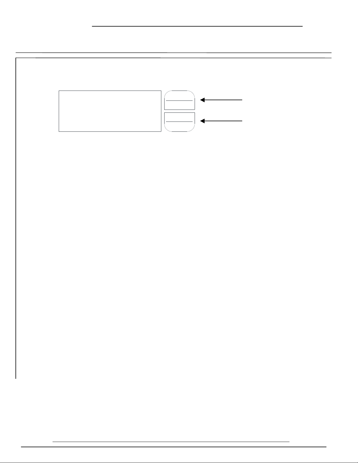
1. To Enter Main Menu Press the Menu/Enter Button
(Time of Day will Flash)
(First Digit will Flash) Example [ 12:00 ]
- To Accept the Digit Value Press the Menu/Enter Button
- Next Digit will Flash to Begin Setting
- Once the Last Digit Display is Accepted all Digits will Flash
3. To Set A.M or P.M. Press the Menu/Enter Button
- To Change Digit Value Press the Set/Change Button Example [ A ]
- To Accept the Digit Value Press the Menu/Enter Button
- Once A.M./P.M. is Accepted the Next Menu Item will Flash
4. To Set the Number of Days between Regeneration Cycles (A) Press the Set/Change Button
- Repeat instructions from step (2) Example [ A -
07]
Notes: 1) Maximum Value is 29
2) If Value Set to 0, Automatic Regeneration will Never Occur
3) Default Setting is 7 days
4) On Metered models an “H” will appear to enter Compensated Hardness Example [ H-20]
5. To Set the Number of Days between Air-Draw Cycles (d) Press the Set/Change Button
- Repeat instructions from step (2) “Used on Centurion Filter Only” Example [ d - 01]
Notes: 1) Maximum Value is 29
2) If Value Set to 0, Air-Draw is Turned Off, but an Air Cycle will still be Completed
when a Regeneration Cycle Occurs. If the Number of Days between Air-Draw Cycles is
set to a Higher Number of Days than the Number of Days between Regeneration Cycles,
it will have No Effect. In Order to turn Off All Cycles, both the Days Between
Regeneration and Days Between Air-Draw Cycles must be Set to 0.
3) Default Setting is 1 day
6. To Exit Main Menu Press the Menu/Enter Button
Page 2
MENU
ENTER
CHANGE
SET
12:00
Menu/Enter
Button
Set/Change
Button
300 – 360 Series
Normal Operation
Electronic Connections
P = Power Supply
B = Powered in Backwash Cycle Only
S = Powered in Entire Regen. Cycle
Control Start-Up Procedures
Page 3
Control Start-Up Procedures (Cont’d)
1. Home Display
- Alternates Between the display of Time of Day and Number of Days Until the Next Regeneration.
- Days Remaining Until the Next Regeneration will Count Down from the entered Regeneration
Day Override Value Until it Reaches 0 Days Remaining.
- A Regeneration Cycle will then be Initiated at the next Designated Regeneration Time
- Metered models alternate the Time of Day and Gallons Left Until the Next Regeneration. The
meter will count down to zero and then regenerate at the scheduled time set.
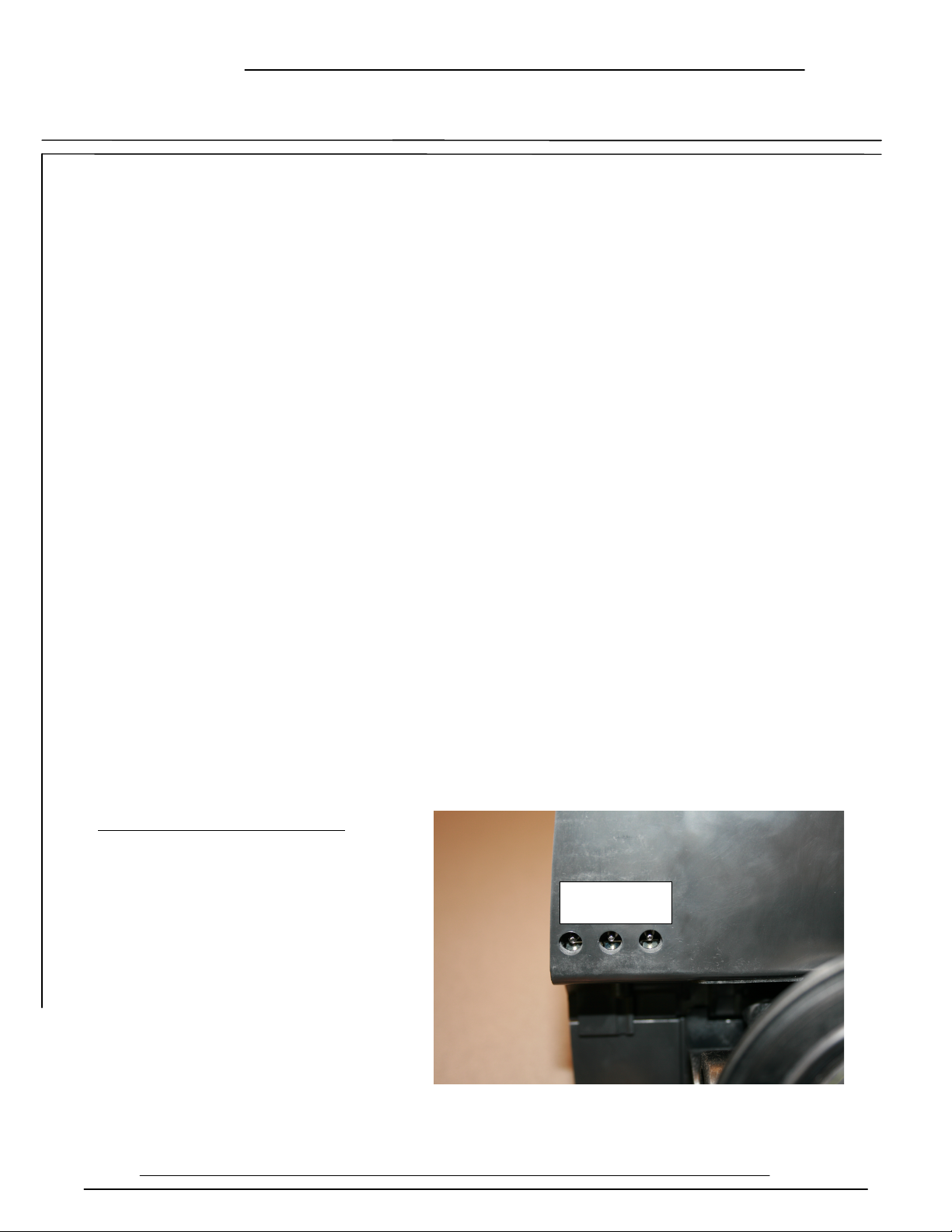
2. Battery Back-Up (Uses a Standard 9-Volt Alkaline Battery)
- Installing the Battery
- Features of Battery Back-Up
Maintains the Time of Day During Power Failures
Notes: 1) During Power Failures, the Display is Turned Off to Conserve Battery Power.
However, to Confirm that the Battery is Working, Press Either Button and
the Display will Turn On for Five Seconds.
2) If Power Failure Occurs while System is Regenerating, the Isobar II Completes its
Current Position and then Pauses Until Power is Restored. The Next Position is then
Commenced from its Beginning.
3) When Used without Battery Back-Up, the Unit Acts Like a Standard Valve—When a
Power Failure Occurs, the Unit Stops at its Current Point in the regeneration Position and
then Restarts at that Point when the Power is Restored. However, the Time will be Offset
by the Increment of Time the Unit was without Power.
P B S

300 – 360 Series
Starting Extra Regeneration Cycle
Control Start-Up Procedures (Cont’d)
Page 4
1. To Start Delayed Extra Cycle Example [ 1 ]
- If Days Remaining Until Next Regeneration does not Read ‘1’, Press and Hold the Set/Change
Button for 3 Seconds Until the Display Reads ‘1’ or ‘0000’ on metered models
- Regeneration Cycle will Initiate at the Next Designated Regeneration Time
2. To Start Immediate Extra Cycle First Complete Above Step
- With Days Remaining Until the Next Regeneration at ‘1’ or ‘0000’
- Press and Hold the Set/Change Button
- After 3 Seconds the Regeneration Cycle will Begin
3. To Fast Cycle Thru Regeneration First Complete Above 2 Steps
Note: Fast Cycling is Not Necessary unless Desired to Manually Step Through Each Cycle Step
- Press and Hold the Set/Change Button for 3 Seconds to Advance to the Next Cycle Step
Softeners Filters
Step 1: Backwash Step 1: Backwash
Step 2: Brine and Rinse Step 2: Rest
Step 3: Rapid Rinse Step 3: Rapid Rinse
Step 4: Brine Refill Step 4: Not used
300 – 360 Series
Centurion Only Regeneration Cycle Step Explanations
Control Start-Up Procedures
Control Start-Up Procedures (Cont’d)
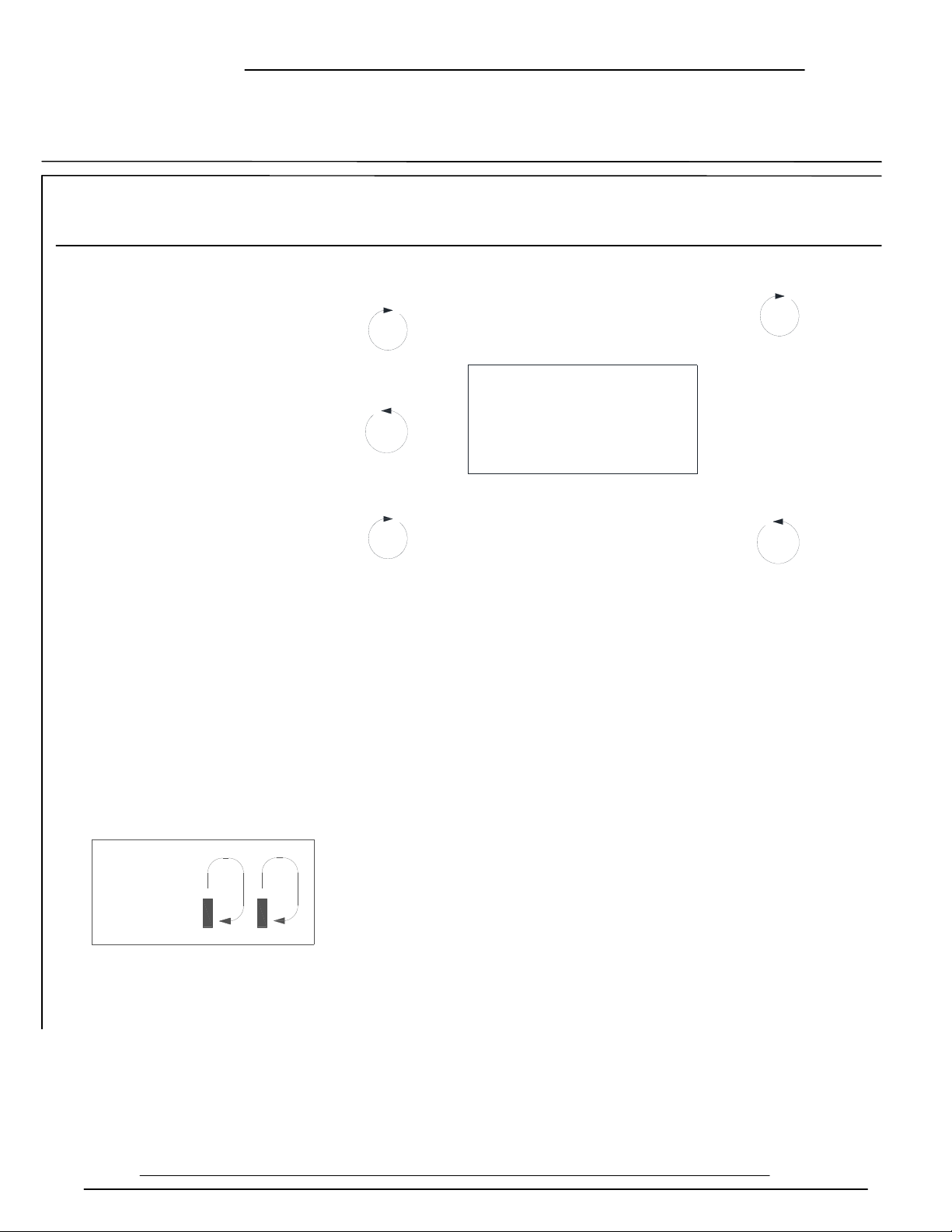
Step 1: Air Release Step
For 3 to 4 Minutes
- Not Programmable
Step 2: Backwash Step
- Default of 20 Minutes
Page 5
Step 3: Rest Step
- Default of 12 Minutes
Step 4: Rapid Rinse Step
- Default of 12 Minutes
Step 5: Air Draw Step
- Default of 12 Minutes
Notes:
- When the Valve is Between Positions, the Display will Flash the Number of the Step it is
Moving Towards.
- The Default Time at Which a Regeneration will Occur is 2:00 A.M.
New feature: The Motor’s Run Direction During a Particular Regeneration Cycle Step is
Indicated by the Rotation Direction of the Last 2 Digit Displays.
MENU
ENTER
CHANGE
SET
2-20
5-

300 – 360 Series
Final Set-Up
Error Codes
Control Start-Up Procedures (Cont’d)
Page 6
With Proper Valve Operation Verified:
1. Add water to the top of the air check. Manually step the valve to the
Brine Draw Position and allow the valve to draw water from the brine tank
until it stops. Note: The air check will check at approximately the midpoint
of the screened intake area.
2. Next, manually step the valve to the Brine Refill Position and allow the
valve to return to Service automatically.
3. With the valve in Service, check that there is about 3.0’ to 5.0’
above the grid in the brine tank, if used.
4. Fill the brine tank with salt to complete Set-Up. The control will run automatically.
There are four (4) error codes which could indicate a possible problem with the control valve:
Error 2 - Homing slot expected. Valve will begin searching for home
(Normal operation continues)
Error 3 - Encoder is not sending a signal
(Valve requires service to continue)
Error 4 - Unable to find homing slot
(Valve requires service to continue)
Error 5 - Motor overload (stalled position or shorted motor)
(Valve requires service to continue)
Error 5 Explanation: The unit thinks the motor is locked. This can only happen when the valve
is running the motor, it is not seeing any encoder slots, and the motor is overloaded. This
usually alerts the presence of corrosion inside the valve clogging the system

300 – 360 Series
Master Programming Mode
To Enter Master Programming Mode, Press and Hold both Buttons for 5 Seconds.
Note: all Master Programming functions have been preset at the factory. Unless a
change is desired, it is NOT necessary to enter Master Programming Mode.
1. Regeneration Type (t)
- This Display is used to set the Regeneration Type. This option setting is identified by the letter ‘t’ in
the left digit. There are two possible settings:
- Timeclock / Filter Delayed – The control will determine that regeneration is required when the set
regeneration time has been reached. The regeneration frequency setting will determine which days a
regeneration cycle will be initiated. Example (t - - c)
- Meter Delayed (Demand) The control will determine that a regeneration is required when the
available volume of softened water drops to or below zero. Regeneration is to begin at the scheduled
time set. Example (t - - d)
• The Set/Change button will adjust this value. To accept the digit value press the
Menu/Enter button.
2. Regeneration Day Override (A) – Meter Mode Only
- Press Menu/Enter button. This display is used to set the maximum amount of time (in days) the unit
can be in service without a regeneration. This option setting is identified by the letter ‘A’ in the left
digit. Regeneration will begin at the scheduled time. A setting of zero will cancel this feature.
- Example: Override every 7 days (A- 07) or Cancel setting (A-00) Maximum setting is 29.
3. To Set Regeneration Time (r) Example [r 12A]
- The time of day at which a regeneration may take place is designated by the letter ‘r’.
- The first display digit indicates A.M or P.M. To change the value press the Set/Change button.
- Press Menu/Enter button to accept the value and move to the next digit.
- The second and third display digits indicate the hour at which the regeneration will occur.
- Change the Digits with the Set/Change button and accept with the Menu/Enter button.
- After the entire display flashes, press the Menu/Enter button to move to the next menu item.
- The next 4 displays set the duration of time in minutes for each regeneration cycle step.
- The step number which is currently modifiable is indicated on the far left of the display screen.
- The number of minutes allotted for the selected regeneration step is displayed on the far right.
- Change the digits values using the Set/Change and Menu/Enter buttons as described above.
Note on Air-Draw Cycle (5): Centurion Filter Only
The longer the unit is set to remain in the air-draw cycle (5), the more air is drawn into the system. A
default setting of 12 minutes draws air down to the level of a normal resin bed height and then returns
the unit to the home display. If the system needs more air, increase the time setting for step (5) or
change the number of days between air-draw cycles to 2-3 days (or lower than your current setting).
There is no way to view the number of days until the next air draw will take place.
Page 7
 Loading...