


FieldShield & FieldShield Flexdrop
Installation Manual
______________________________________________________
Manual 018956 REV A- July 2017

FieldShield & FieldShield Flexdrop
Installation Manual
Table of Contents
When to push, pull, or both? 3
Recommended Installation Distances 3
Fiber Installation 4
Attaching Pull String to Fiber 5
Pre-Terminated Pushable LC Drops 6
Pre-Terminated Pushable LC Drops 6
Terminating Fiber 7
Connector Cleaning 7
SC Pushable Connector 9
Simplex LC Pushable Connector 10
Duplex LC Pushable Connector 11
Fiber Polarity Switch 12
Preparing FieldShield Pushable Fiber for
Splice-On Connectors 13
CraftSmart Splice-On Connectors 19
Drop Cable Options 22
Standard Warranty 23
Proprietary Notice 24
Technical Support 24
_________________________________________________________
2
Direct: 763.476.6866 • National: 800.422.2537 • www.SeeCleareld.com • techsupport@clfd.net
Manual 018956 REV A- July 2017

FieldShield & FieldShield Flexdrop
__________________________________________________________
When to push, pull, or both?
Every situation is different, but as a general rule, it is typically easier to install
ber using a push and pull combination, rather than pushing or pulling by itself.
By using a combination push/pull method, installers have access to the ber
from both ends of the microduct when troubleshooting.
Recommended Installation Distances
Installation Manual
NOTE: If a ber gets stuck or snags during installation, the ber can be pulled back a couple inches from the end being fed into the duct and repulled past the bind point. Sometimes the connector needs to be rocked past a snag point by carefully alternating pushing and pulling from both
ends.
Direct: 763.476.6866 • National: 800.422.2537 • www.SeeCleareld.com • techsupport@clfd.net
3
Manual 018956 REV A- July 2017

FieldShield & FieldShield Flexdrop
Installation Manual
Fiber Installation
Whether pre-connectorized or not, here are a couple quick tips to use when installing pushable ber into the microduct.
These techniques have been used to install single ber, connectorized ber and multi-ber assemblies at distances in
excess of 500 feet.
_________________________________________________________
● Never Remove Protective Cover from Pushable Connectors Prior to Installation
If the protective plastic cover is removed from a pre-connectorized pushable
assembly before you place the ber in the microduct, the connector acts as a sort of
“cheese grater” down the length of the microduct. It will shave off the inner liner and
then those particles bind around the ber. In some cases, this causes the ber to
become stuck and usually results in a broken ber.
● Pulling is Faster than Pushing
● Pull with Constant Pressure and Speed to Overcome Initial Friction
● Maintain the Same Feed and Pull Rate on Both Ends
4
Direct: 763.476.6866 • National: 800.422.2537 • www.SeeCleareld.com • techsupport@clfd.net
Manual 018956 REV A- July 2017

FieldShield & FieldShield Flexdrop
__________________________________________________________
Attaching Pull String to Fiber
FieldShield Microduct comes preinstalled with a nylon pull string that can handle pull strengths up to 50 lbs. When attaching
the pull string, never tie the pull string directly to the ber or connector. This will cause damage to or pull the connector off.
Also, never use tape over the string because the outside jacket of the ber is slippery enough that tape usually comes off
and clogs the microduct. Depending upon connector type there are two different methods to attach the pull string to the
pushable ber assembly.
Pre-Terminated Pushable SC and Blunt Drops
The rst method uses a nylon pulling eye that slides over the end of the assembly and works with blunt drops as well as
pre-terminated SC pushable assemblies.
Step 1: Slide the open end of the pulling eye over the plastic sheath of the SC Pushable Connector or the
blunt end of the assembly (Figure 1). Make sure to push the assembly all the way to the end of the pulling
eye and pull the pulling eye taut (Figure 2).
Installation Manual
Step 2: After the nylon pulling eye has been
slid over the end of the cable, simply tie
the pull string to the loop of the pulling eye
(Figure 3).
Figure 3
Direct: 763.476.6866 • National: 800.422.2537 • www.SeeCleareld.com • techsupport@clfd.net
Manual 018956 REV A- July 2017
Figure 2Figure 1
Note: When using SC Pushable Connectors,
make sure to cut back the excess string left
behind after tying the pull string to the pulling
eye. Failure to remove the excess string can
cause the connector to bind between the
string and the microduct during installation.
5

FieldShield & FieldShield Flexdrop
Installation Manual
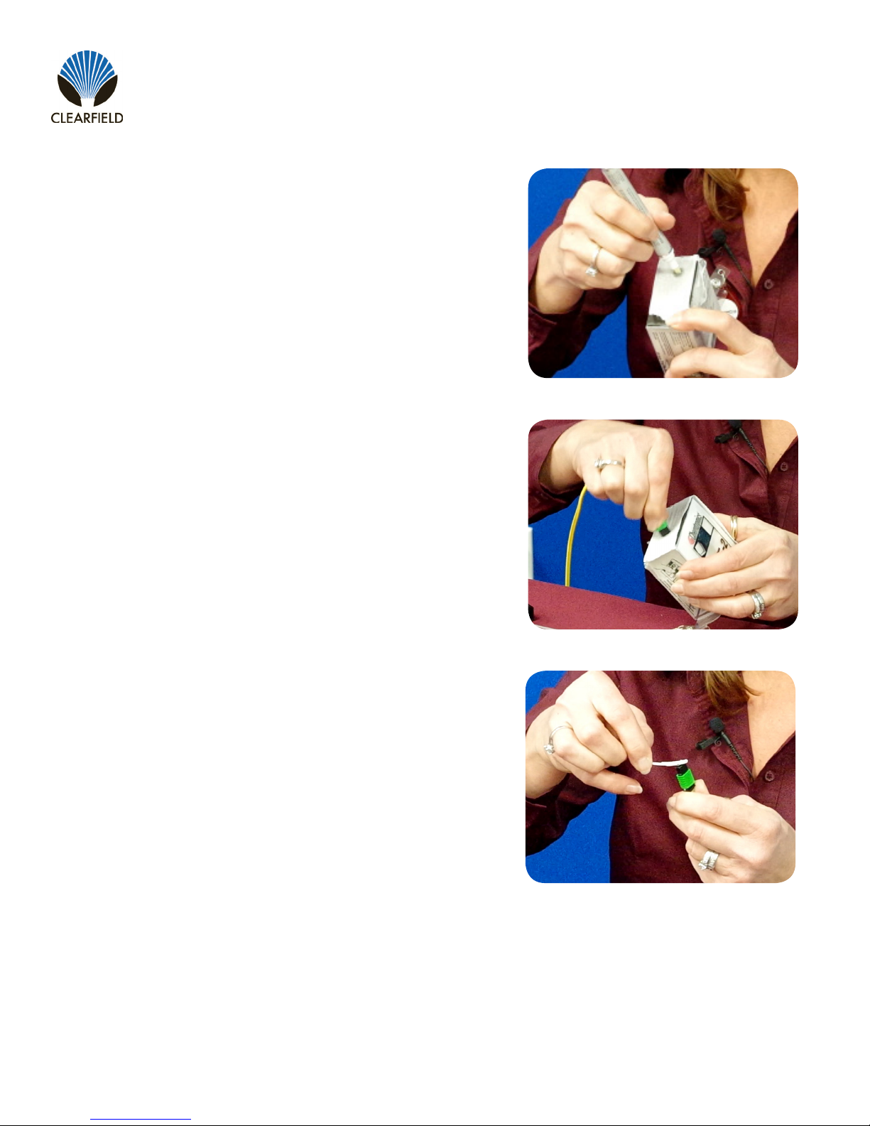
Pre-Terminated Pushable LC Drops
The second method uses a crimped pulling eye that was attached to the assembly during factory termination.
Installation Procedure
Step 1: Access the pulling eye by sliding the
connector’s protective sheath approximately 1”
towards the opposite end of the assembly, stopping at the metal crimp ring.
_________________________________________________________
Figure 1
Step 2: Tie the pull string to the loop of the
pulling eye and cut back the excess string left
behind.
Note: Do not to cut the string directly at the knot.
Leave about 2 to 3 mms of excess string next to
the knot.
Step 3: Make sure that the springs are staggered
one on top of each other then, push the
protective sheath over the connector and knot
from the pull string.
Note: Failure to stagger the springs increases
the width of the pushable connector, making it too
wide to pass tight corners.
Figure 2
6
Direct: 763.476.6866 • National: 800.422.2537 • www.SeeCleareld.com • techsupport@clfd.net
Figure 3
Manual 018956 REV A- July 2017

FieldShield & FieldShield Flexdrop
__________________________________________________________
Connector Cleaning Procedure
Whether factory terminated or eld spliced, clean connectors are essential
for proper system operation. Even the smallest dust particle can cause
transmission problems, so for optimal network performance, inspect and if
necessary, clean all connectors and adapters prior to mating.
I.T.C…Inspect Then Connect!
ALWAYS inspect the connector rst thing with a clean ber scope inspect
the pair. Three types of contamination require different cleaning techniques.
The use of Chemtronics end face and bulkhead cleaning products and
techniques ensures a clean end face, no matter the type of contamination.
These are Cleareld recommended products/application. Use the product
you feel will complete your cleaning procedures. Create a “best practice” for
your company and follow those procedures.
Installation Manual
Figure 1
**NOTE: It is NOT recommended to use IPA to clean the end-face.
Cleaning the end-face…but not just the end-face
• Place one wiping paper on QbE-2 FiberSafe™ Cleaning Platen. Figure 1
• Apply small amount of precision cleaner (about 1” in diameter) with Electro-Wash MX pen on to one end of the wipe. Figure 2
• Hold end face 90 degree. Adjust for APC connection by slightly tilting the
container or end face. Angle is correct when no drag is left on the end face.
Figure 3
• Draw end face from wet to dry part of the wipe 3 times. Use just enough
pressure to ensure complete contact between end face and the wipe.
DO NOT retrace previous step.
Figure 2
Figure 3
Direct: 763.476.6866 • National: 800.422.2537 • www.SeeCleareld.com • techsupport@clfd.net
7
Manual 018956 REV A- July 2017

FieldShield & FieldShield Flexdrop
Installation Manual
• CLEAN THE FERRULE…Lightly moisten the ber optic swab
(2.5mm/38542F or 1.25mm/38040) by spotting a small amount (about 1”)
of Electro-Wash PX or Electro-Wash MX pen onto the QBE-2. Hold the
swab, 1 side down to the wetted area and hold for a count of 1-2-3-4-5.
Figure 4
• Insert swab into side of ferrule, wet side to the ceramic ferrule and
circle around 2-3 times and remove. Turn swab to dry side and repeat.
Figure 5
_________________________________________________________
Cleaning the mate through a bulkhead adapter AND the
adapter itself!
• Lightly moisten the ber optic swab(2.5mm/38542F or 1.25mm/38040)
by spotting a small amount (about 1”) of Electro-Wash PX or Electro-Wash MX pen onto the QBE-2. Hold the tip of the swab onto the
wetted area and hold for a count of 1-2-3-4-5.
• Insert the swab into the adapter to the connector, press lightly against
the connector, twist 2-3 times, remove and discard.
• Dry with a second dry swab.
• Inspect (re-clean if necessary) and test for signal strength.
• Use additional swabs to clean inside the actual adapter. Moisten swab,
like above, insert through hole and remove while twisting. Figure 6
Figure 4
Figure 5
8
Direct: 763.476.6866 • National: 800.422.2537 • www.SeeCleareld.com • techsupport@clfd.net
Figure 6
Manual 018956 REV A- July 2017
FieldShield & FieldShield Flexdrop
__________________________________________________________
Cleaning an MPO/MTP Connector
Female Connector
• Place one wiping paper on QbE-2 FiberSafe™ Cleaning Platen and
apply small amount of precision cleaner (about 1” in diameter) with Electro-Wash MX pen on to one end of the wipe. Figure 1
• Hold end face 90 degree. Adjust for APC connection by slightly tilting
the container or end face. Angle is correct when no drag is left on the end
face. Figure 2
Installation Manual
Figure 1
Male Connector
• Lightly moisten the ber optic swab (CC505F) like above, moistening 1
side.
• Place swab, wet side down at one end of connector end-face and draw
across in a diagonal sweep (ie: from ber 1 up and across to ber 12).
Turn swab over to dry and draw back from ber 12 to ber 1. Figure 3
BEFORE cleaning any connector…be sure you know what type of contaminate you are cleaning…dry? Fluidic?...All the available products are
good, it’s the process that you need to be aware of. Using a dry cleaning
method to clean “dirt” can lead to scratching of the end-face. Learn the
process of cleaning properly!
Figure 2
Figure 3
Direct: 763.476.6866 • National: 800.422.2537 • www.SeeCleareld.com • techsupport@clfd.net
9
Manual 018956 REV A- July 2017

FieldShield & FieldShield Flexdrop
Installation Manual
SC Pushable Connector
Housing Assembly
Step 1: Remove the white protective dust cap from the
unassembled connector (Figure 1).
Note: The SC Pushable Connector has a keyed locking
feature that holds the inner housing to the connector and
aligns the ferrule when the two are correctly mated.
To properly mate the connector, the key on the inner housing
must bypass the ferrule alignment notch to properly lock into
place.
Step 2: Align the black mark on the inner housing with the
black line on the connector, then rotate the inner housing
45 degrees to offset the lock (Figure 2) and slide the inner
housing half way over the connector.
_________________________________________________________
Figure 1
Step 3: Rotate counter-clockwise 45 degrees to realign the
inner housing and connector and push the inner housing onto
the connector until it snaps into place (Figure 3).
Step 4: Align the key on the outer housing with the black line
on the connector, then slide the outer housing over the entire
assembly until it snaps into place (Figure 4).
Step 5: Re-install the white protective dust cap (Figure 5).
Figure 2
Figure 3
Figure 4
10
Direct: 763.476.6866 • National: 800.422.2537 • www.SeeCleareld.com • techsupport@clfd.net
Figure 5
Manual 018956 REV A- July 2017

FieldShield & FieldShield Flexdrop
__________________________________________________________
Simplex LC Pushable Connector
Connector Housing Assembly
Step 1: Remove protective dust cap and cut the pull
string loop close to crimp (Figure 1).
Step 2:
A. Slide the inner clip over the ber (Figure 2).
B. Align slot with housing latch and press together.
Note: APC connectors will have dots on the ferrule to
align with latch on housing.
Installation Manual
Figure 1
Figure 2
Step 3: Insert the cable crimp into the back of the lower body (Figure 3). Snap the connector into the front
half of the lower body (Figure 4).
Figure 3 Figure 4
Step 4: Snap body cover onto lower half (Figure 5). Install the protective dust cap (Figure 6).
Figure 5
Direct: 763.476.6866 • National: 800.422.2537 • www.SeeCleareld.com • techsupport@clfd.net
Figure 6
11
Manual 018956 REV A- July 2017

FieldShield & FieldShield Flexdrop
Installation Manual
Duplex LC Pushable Connector
Connector Housing Assembly
Step 1: Remove protective dust cap and cut the pull
string loop close to crimp (Figure 1).
Step 2:
A. Slide inner clips on the same colored ber and
over the springs (Figure 2).
B. Align slot with housing latch and press together.
_________________________________________________________
Figure 1
Note: APC connectors will have dots on the ferrule to
align with latch on housing.
Step 3: Insert the cable crimp into the back of the lower body (Figure 3). Snap the connector into the front
half of the lower body (Figure 4).
Figure 3 Figure 4
Step 4: Snap body cover onto lower half (Figure 5). Install the protective dust cap (Figure 6).
Figure 2
Figure 5
12
Direct: 763.476.6866 • National: 800.422.2537 • www.SeeCleareld.com • techsupport@clfd.net
Figure 6
Manual 018956 REV A- July 2017

FieldShield & FieldShield Flexdrop
__________________________________________________________
Fiber Polarity Switch
Step 1: Remove the top half of the body by prying the
bottom half sides apart (Figure 1).
Step 2: Remove the lower half of the body (Figure 2).
Installation Manual
Figure 1
Figure 2
Step 3: Choose either a straight through or reversed polarity conguration and assemble the colored bers
as shown.
Note: All pre-assembled Cleareld Dual LC connectors are factory congured as straight through.
Straight Through Reversed
Step 4: Snap body cover onto lower half (Figure 3).
Direct: 763.476.6866 • National: 800.422.2537 • www.SeeCleareld.com • techsupport@clfd.net
Figure 3
13
Manual 018956 REV A- July 2017

FieldShield & FieldShield Flexdrop
Installation Manual
Preparing FieldShield Pushable Fiber for Splice-On Connectors
1-Fiber 250um FieldShield Cable
Recommended Tools / Parts List
_________________________________________________________
• 1/8 Inch Adhesive Lined Heatshrink
• 900um Furcation Tubing
• 3-4mm Rotary Tube Cutter
• Snips/Cutting Utensil
Installation Procedure
Step 1: Determine the required 900um breakout
length needed for your application and mark the
FieldShield cable using an appropriate writing
utensil (Figure 1).
Step 2: Ring cut and remove the jacket using
a rotary tube cutter available from Cleareld
(Figure 2).
• Isopropyl Alcohol /Cleaning Wipes
• Heat Source (Hot Air Gun/Blow Torch)
• Super Glue
• Ruler
Figure 1
14
Note: The jacket is removed using a score and
snap process. Make sure that the rotary tube
cutter blade has been adjusted so that it scores
the outside of the jacket, but does not entirely cut
through. Do not cut or nick the ber.
Figure 2
Step 3: Pulling from the cable, pull the 3mm
jacket off in a straight line (Figure 3).
Figure 3
Direct: 763.476.6866 • National: 800.422.2537 • www.SeeCleareld.com • techsupport@clfd.net
Manual 018956 REV A- July 2017

FieldShield & FieldShield Flexdrop
__________________________________________________________
Step 4: Using a cleaning wipe and some Isopropyl alcohol, wipe clean the exposed 250um ber
(Figure 4).
Step 5: Cut a piece of 900um furcation tubing
6” longer than the desired breakout. Mark the
900um tubing 6” from the end of the cut (Figure
5). This 6 inch mark will tell you how far to insert
the 900um tubing into the 3mm cable.
Installation Manual
Figure 4
Step 6: Cut a 1” piece of 1/8” adhesive lined
heatshrink (available from Cleareld), fold the
Kevlar strength members back over the outside
of the cable. Slide the heatshrink over the ber
and on to the outside of the 3mm cable holding
back the Kevlar (Figure 6).
Step 7: Place heatshrink ush to the end of the
cable and then apply even heat until the tubing is
fully shrunk (Figure 7).
Figure 5
Figure 6
Direct: 763.476.6866 • National: 800.422.2537 • www.SeeCleareld.com • techsupport@clfd.net
Figure 7
15
Manual 018956 REV A- July 2017

FieldShield & FieldShield Flexdrop
Installation Manual
Step 8: Slide the 900um tubing over the 250um
ber inserting the 900um tube into the FieldShield
3mm cable (Figure 8).
Step 9: Stop inserting the 900um tubing keeping
the 6 inch mark approximately 1 inch from going
into the 3mm cable as seen in (Figure 9).
_________________________________________________________
Figure 8
Step 10: Now apply a generous amount of super
glue to the 900um furcation tubing between the
FieldShield cable and the mark and then while
rotating, slide the furcation tubing up to the 6 inch
mark on the 900um tubing (Figure 10).
Step 11: Allow the glue to dry, and then trim the
excess Kevlar strength members behind the
heatshrink (Figure 11).
Note: The CraftSmart Splice-On Connector can
now be installed per standard instructions to the
900um furcated ber.
Figure 9
Figure 10
16
Direct: 763.476.6866 • National: 800.422.2537 • www.SeeCleareld.com • techsupport@clfd.net
Figure 11
Manual 018956 REV A- July 2017

FieldShield & FieldShield Flexdrop
__________________________________________________________
2, 6, and 12-Fiber 250um FieldShield Cable
These instructions detail the installation of 2, 6, and 12 ber 900um furcation upjacketing kits. Each kit breaks out 250um
bers from a multiber loose tube into individual 900um buffer tubes. The ber can then be terminated using the 900um
CraftSmart Splice-On Connector installation instructions.
Recommended Tools / Parts List
Installation Manual
• Cover
• Base
• 24” 900um 2, 6, or 12 Fiber Terminal
Assembly
• Heatshrink
• Heat Source (Hot Air Gun/Blow Torch)
Installation Procedure
Step 1: Locate and setup your work surface as close to the patch panel location as possible. This will minimize the strip
length.
Step 2: Route the cable through the patch panel to the work surface.
Step 3: Measure backwards, from the end of the cable to the point at which it will attach to the patch panel, and add 39
inches (1 meter) to the length. Mark this length with a piece of tape. This is the strip point for the cable being
terminated.
Step 4: Strip the cable back to the tape mark.
Step 5: Secure the cable to the patch panel.
Step 6: Clean any dirt and/or gel surrounding the loose tube.
Step 7: Select the rst buffer tube and measure back 36 inches (90cm) and place a mark.
Step 8: Score the buffer tube and strip the loose buffer tube at the mark.
Step 9: Thread the heatshrink until it is ush with the end of the buffer tube and shrink in place.
Note: Be careful not to melt or distort the tube due to excessive heat.
• Electrical or Masking Tape
• Lint Free Wipes
• Indelible Marker
• Buffer Tube Stripper
• Gel Cleaner
• Needle Nose Pliers
Step 10: Tape the buffer tube to the work surface with 2 inches (50mm)
overhanging the end of the work surface (Figure 1).
Step 11: Wipe all the gel from the exposed bers using a gel cleaner.
Direct: 763.476.6866 • National: 800.422.2537 • www.SeeCleareld.com • techsupport@clfd.net
Figure 1
17
Manual 018956 REV A- July 2017

FieldShield & FieldShield Flexdrop
Installation Manual
Step 12: Place the buffer tube in the bottom of the furcation kit. Using pliers, press the tabs of the crimping xture to hold
the loose tube.
Note: Crimp only enough to start to deform the tube. Twist and pull the terminal body to check if the crimp is
secure. The tube should not slip or move in the crimp xture.
Step 13: Tape the terminal assembly in the vertical position 3 inches (75mm)
to the side of the loose buffer tube (Figure 2).
_________________________________________________________
Figure 2
Step 14: Untangle the bers and make sure they are completely free of gel lling compound.
Step 15: Talc the bers to facilitate the threading operation. Cup the talc in the palm of your hand and apply along the whole
length of the bers.
Step 16: Select the blue ber and thread 6 inches (150mm) into the blue tube
of the terminal assembly (Figure 3).
Repeat this procedure for the remaining bers, making sure the
color coded bers match the color coded 900um tubing.
Step 17: When all bers have been threaded, push the bers as a group until
the bers start to protrude from the ends of the buffer tubes.
Step 18: Gently pull the bers from the ends of the buffer tubing.
Figure 3
Note: Do not pull the bers taught. Leave sufcient slack so the bers are not stressed.
Step 19: Untape the buffer tube assembly and slide the assembly toward
the loose tube while pulling the bers from the end of
the 900um tubing. If the bers twist, rotate the terminal assembly in
the opposite direction of the twist (Figure 4)
18
Direct: 763.476.6866 • National: 800.422.2537 • www.SeeCleareld.com • techsupport@clfd.net
Figure 4
Manual 018956 REV A- July 2017

FieldShield & FieldShield Flexdrop
__________________________________________________________
Step 20: Place the terminal assembly into the bottom of the terminal body.
Align the top cover and snap into place (Figure 5).
Step 21: Remove the tape from the loose tube and repeat this procedure for the remaining loose tubes.
Note: The CraftSmart Splice-On Connector can now be installed per standard instructions to the 900um furcated
ber.
Installation Manual
Figure 5
Direct: 763.476.6866 • National: 800.422.2537 • www.SeeCleareld.com • techsupport@clfd.net
19
Manual 018956 REV A- July 2017

FieldShield & FieldShield Flexdrop
Installation Manual
CraftSmart Splice-On Connectors
Safety Precautions
• Please read and follow all fusion splicer manufacturer recommended procedures concerning splicing operation and
precautions.
• Safety glasses should be worn when handling cleaved bers. Cleaved bers are sharp and can pierce eyes, skin or
clothing.
• Never look into the end of a microscope or optical cable connected to an operating optical output device. Laser radiation
is invisible, and direct exposure can severely injure the human eye.
Note: Before starting this process, completely read through the entire installation document. If the splice machine you are
using has a tensile test option, be sure to shut this option off on your machine.
Recommended Tools/Parts List
1. Fusion Splicer
2. Cleaver
3. Jacket Ringer and Stripper
4. Kevlar Shears
5. Fiber Stripper
6. Splice Holders for Splicer
7. Marking Pen
_________________________________________________________
Installation Procedure
Step 1: Remove the connector and components from
the individually packaged tube.
Step 2: Separate all the parts and identify the parts
you will be using for your application.
• Dust Cap with Handle
• Outer Housing
• Inner Housing Connector Assembly
• Fusion Splice Protection Sleeve
• Strain Relief Boot
Step 3: Remove the dust cap from the connector
sub-assembly and put aside for later use (Figure 1).
Figure 1
Figure 2
20
Direct: 763.476.6866 • National: 800.422.2537 • www.SeeCleareld.com • techsupport@clfd.net
Figure 3
Manual 018956 REV A- July 2017

FieldShield & FieldShield Flexdrop
__________________________________________________________
Step 4: Remove Install the dust cap with the
handle on to the ferrule (Figure 2).
Step 5: Carefully remove the ber protection cover
from the back side of the connector (Figure 3).
Do not to touch the stripped end of the ber or let
anything bump against it.
Note: The Fiber is already stripped,
cleaned and cleaved to the exact
dimension needed.
Installation Manual
Figure 2
Figure 3
Step 6: Insert the connector sub-assembly in to
the fusion splice holder, making sure the ber sits
into the center of the ber groove (Figure 4).
Figure 4
Step 7: Following the splice machines
instructions carefully insert the splice holder with
the connector inside of the holder into one side of
the machine (Figure 5). Using extreme caution,
do not touch or bump the stripped ber against
anything.
Figure 5
Step 8: Insert the Strain Relief Boots narrow end rst on to the 900um ber that you will be splicing to.
Step 9: Insert the Fusion Splice Protection Sleeve on to the 900um ber after the Strain Relief Boot.
Step 10: Following the Fusion Splicer’s manufacturers recommendations strip the ber to length.
Direct: 763.476.6866 • National: 800.422.2537 • www.SeeCleareld.com • techsupport@clfd.net
21
Manual 018956 REV A- July 2017

FieldShield & FieldShield Flexdrop
Installation Manual
Step 11: Place the ber in the splice holder.
Step 12: Clean bare ber with clean wipe and alcohol.
Step 13: Cleave the bare ber to 10mm. If the cleave length is too long it will not be protected in the
Splice Protection Sleeve.
Step 14: Following the splice machines instructions carefully insert the splice holder with the 900um
ber into the opposite side of the machine. Using extreme caution, do not touch or bump the stripped
ber against anything.
Step 15: Following the Fusion Splicer’s manufacturers procedure splice the connector to the ber.
Step 16: Once the splicer has completed the process and you are satised with the results, carefully
slide the protection sleeve up to the ber holder and remove the ber and connector from the splicer.
_________________________________________________________
Step 17: Slide the protection sleeve toward the
connector centering it over the stripped bare ber
splice (Figure 6).
Step 18: Insert the ber and protection sleeve
into the protection sleeve oven with the connector
all the way to one side of the oven keeping it out
of the oven as the best as you can (Figure 7). If
you cannot close the ovens cover then you can
lay the splice protection holder over the protection sleeve to help keep the heat inside.
Note: If the splice protection sleeve is
not shrunk down all the way then you
can run the heat cycle again. You may
want to increase the ovens time duration
if this continues to happen.
Figure 6
Figure 7
Step 19: Slide the Strain Relief Boot up to the back of the connector and snap in place.
Step 20: Replace the dust cap with handle back to the original dust cap.
22
Direct: 763.476.6866 • National: 800.422.2537 • www.SeeCleareld.com • techsupport@clfd.net
Manual 018956 REV A- July 2017
__________________________________________________________
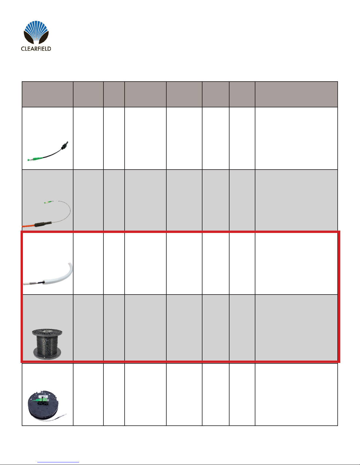
Drop Cable Options
FieldShield & FieldShield Flexdrop
Installation Manual
Product
Name
FieldShield
FLATdrop
FieldShield
D-ROP
FieldShield
FLEXdrop
Cable
Jacket
Outdoor Yes -40° to 176°F No Black Yes
Outdoor Yes -40° to 176°F Yes
Indoor
(Plenum)/
Outdoor
UV Temperature
Yes -40° to 176°F Yes
FieldShield
Connector
Jacket
Color
Black/
Orange
Black/
White
Can be
stapled
Yes
Yes
Best
Application
For use when fast installation
and low up-front cost is most
desired feature.
For use when a single pass
and restorable solution at a
competitive price is ideal.
For use when a premium
product that has maximum
workability, exibility and
restorability is desired.
FieldShield
(Classic)
Outdoor
in Duct
FieldShield
StrongFiber
Indoor/
Outdoor
in Duct
Direct: 763.476.6866 • National: 800.422.2537 • www.SeeCleareld.com • techsupport@clfd.net
Yes in
Duct
Yes in
Duct
-40° to 176°F Yes Black Yes
-40° to 176°F Yes Black
Manual 018956 REV A- July 2017
Yes in
Duct
For use when the distance
from the access point to the
SFU/MDU is longer than
normal and a more rigid solu-
tion is required to maintain
restorability for drops longer
than 300 feet.
For use when a reusable
pathway is needed and
maximum slack storage is
desirable.
23

FieldShield & FieldShield Flexdrop
Installation Manual
Standard Warranty
Cleareld warrants to the original purchaser of the Product sold hereunder is free from defects in material and workmanship under normal use and
service, subject to exceptions stated herein.
Product Warranty
Products manufactured by Cleareld to customer prints and/or specications are warranted for one (1) year or in accordance with the Product Warranty Classication section of this document. In all cases, the warranty period commences on the date of shipment to the original purchaser.
Warranty Claim Procedure
If any Product purchased from Cleareld is found defective under the above warranty, the following basic procedure must be followed:
a) Customer must contact Cleareld and obtain a Return Materials Authorization.
b) Following authorization, the Customer ships the product per Cleareld’s freight instructions to Cleareld’s manufacturing facility.
c) Cleareld shall repair or replace the defective Product at its sole option and discretion, and return the repaired or replacement Product to Customer’s site, freight prepaid.
_________________________________________________________
Note: If the Product is not found to be defective at Cleareld, the product will be returned to the Customer and the customer billed for freight in both
directions.
Limitations of Warranty
CORRECTION OF DEFECTS BY REPAIR OR REPLACEMENT, AT THE OPTION OF CLEARFIELD INC, SHALL CONSTITUTE THE EXCLUSIVE
SOLE REMEDY FOR A BREACH OF THIS LIMITED WARRANTY. CLEARFIELD SHALL NOT BE LIABLE UNDER ANY CIRCUMSTANCES FOR
ANY SPECIAL, CONSEQUENTIAL, INCIDENTAL, PUNITIVE, OR EXEMPLARY DAMAGES ARISING OUT OF OR IN ANY WAY CONNECTED
WITH THE PRODUCT OR WITH AGREEMENT TO SELL PRODUCT TO BUYER, INCLUDING, BUT NOT LIMITED TO DAMAGES FOR LOST
PROFITS, LOSS OF USE, OR FOR ANY DAMAGES OR SUMS PAID BY BUYER TO THIRD PARTIES. THE FOREGOING LIMITATION OF LIABILITY SHALL APPLY WHETHER THE CLAIM IS BASED UPON PRINCIPLES OF CONTRACT, WARRANTY, NEGLIGENCE OR OTHER TORT,
BREACH OF STATUTORY DUTY, PRINCIPLES OF INDEMNITY OR CONTRIBUTION, THE FAILURE OF ANY LIMITED OR EXCLUSIVE REMEDY
TO ACHIEVE ITS ESSENTIAL PURPOSE, OR OTHERWISE.
CLEARFIELD WILL NOT BE RESPONSIBLE FOR ANY LABOR OR MATERIALS COSTS ASSOCIATED WITH INSTALLATION OR INCORPORATION OF CLEARFIELD PRODUCTS AT CUSTOMER SITES, INCLUDING ANY COSTS OF ALTERATION, REPLACEMENT OF DEFECTIVE
PRODUCT, OR ANY FIELD REPAIRS.
Other Limitations
Cleareld assumes no warranty liability regarding defects caused by:
1) Customer’s modication of Product, excepting installation activities described in Cleareld documentation.
2) Customer re-packaging of Product for shipment to third parties or destinations other than those originally shipped to by Cleareld, or any defects
suffered during shipping where the Product has been re-packaged.
3) Customer’s installation or maintenance, excepting activities described in and performed in accordance with Cleareld documentation.
4) Customer’s improper or negligent use or application of Product.
5) Other causes external to the Product, including but not limited to accidents, catastrophe, acts of God, government action, war, riot, strikes, civil
commotion, sovereign conduct, or the acts or conduct of any person or persons not party to or associated with Cleareld.
6) Environmental factors and weathering resulting in aging and damage not necessary or applicable to the function of the product.
24
Direct: 763.476.6866 • National: 800.422.2537 • www.SeeCleareld.com • techsupport@clfd.net
Manual 018956 REV A- July 2017

FieldShield & FieldShield Flexdrop
__________________________________________________________
Proprietary Notice
About FieldShield Product Line Application
Information contained in this document is copyrighted by Cleareld, Inc. and may not be duplicated in full or part by any person without prior written
approval of Cleareld, Inc.
Its purpose is to provide the user with adequately detailed documentation to efciently install the equipment supplied. Every effort has been made to
keep the information contained in this document current and accurate as of the date of publication or revision.
However, no guarantee is given or implied that the document is error free or that it is accurate with regard to any specication.
Technical Support
Cleareld, Inc. can be contacted for any issues that arise with the supplied product.
If you need to return the supplied product, you must contact the Cleareld, Inc. Customer Service Department to request a Returned Materials
Authorization (RMA) number.
Installation Manual
Cleareld, Inc.
7050 Winnetka Ave N
Minneapolis, MN 55428
Toll Free: 800.422.2537
Phone: 763.476.6866
Fax: 763.475.8457
Customer Support: sales@clfd.net
Technical Support: techsupport@clfd.net
Direct: 763.476.6866 • National: 800.422.2537 • www.SeeCleareld.com • techsupport@clfd.net
25
Manual 018956 REV A- July 2017
 Loading...