

Clearaudio Unify series, Unify 9 inch, Unify 10 inch, Unify 12 inch, Unify 14 inch User Manual
Page 1

User manual
Bedienungsanleitung
© clearaudio
electronic GmbH, 2018/10 Made in Germany
Unify
Page 2
User manual / Bedienungsanleitung
2 © clearaudio electronic GmbH, 2018/10
User manual ..............................................................2 - 10
Bedienungsanleitung .................................................11 - 19
Dear Clearaudio customer,
Thank you for purchasing the Clearaudio
Unify
radial tonearm.
This tonearm is manufactured to the highest degree of tolerance and quality.
Please read this instruction manual carefully, to avoid any damage or loss of warranty.
This manual will help you achieve an easy setup and guarantees the highest pleasure for a long
time.
We wish you a lot of listening pleasure with your new Clearaudio
Unify
tonearm.
Clearaudio electronic GmbH
Warning
Do not expose the equipment to rain or moisture.
Do not handle the mains lead with wet hands.
No naked ame sources, such as lighted candles, should be placed on the equipment.
Only for use on turntables.
CE-MARKIERUNG
Page 3

User manual / Bedienungsanleitung
Made in Germany 3
Contents
1. Packing contents ......................................................... 4
2.
Unify
tonearm mounting ............................................. 5 - 9
3. Special notes ............................................................... 9
4. Technical data ............................................................. 10
Warranty .......................................................................... 20 - 21
Page 4
User manual / Bedienungsanleitung
4 © clearaudio electronic GmbH, 2018/10
1. Packing contents
Clearaudio has developed special and secure packing for your
Unify
tonearm that ensures safe
transportation.
Please keep this original packing, you will need it if you need to ship the tonearm.
Please check the contents as shown in the list of this page:
1.
Unify
carbon bre tonearm with
Clearaudio Sixstream Super Wire
6. Antiskating weight
2.
Unify
tonearmbase 7. Socket head cap screw and washer for
cable strain relief
3. Clearaudio turboweight 8. Socket head cap screw and wahser for use
with cartridge spacer/weight above
4. 1x hex wrench 2.5mm
1x hex wrench 3mm
9. Cartridge alignment gauge
5. Additional weight for lower weight
cartridges
10. Clearaudio user manual, warranty and
quality card, return delivery note
Recommended Tools:
• Clearaudio Cartridge alignment gauge (Art. No. AC005/IEC)
• Clearaudio Weight Watcher (Art. No. AC094)
Both items and more accessoires are available at www.analogshop.de.
Page 5
User manual / Bedienungsanleitung
Made in Germany 5
2.
Unify
tonearm mounting
Please keep in mind that these directions are for mounting the
Unify
tonearm on any Clearaudio
turntable.
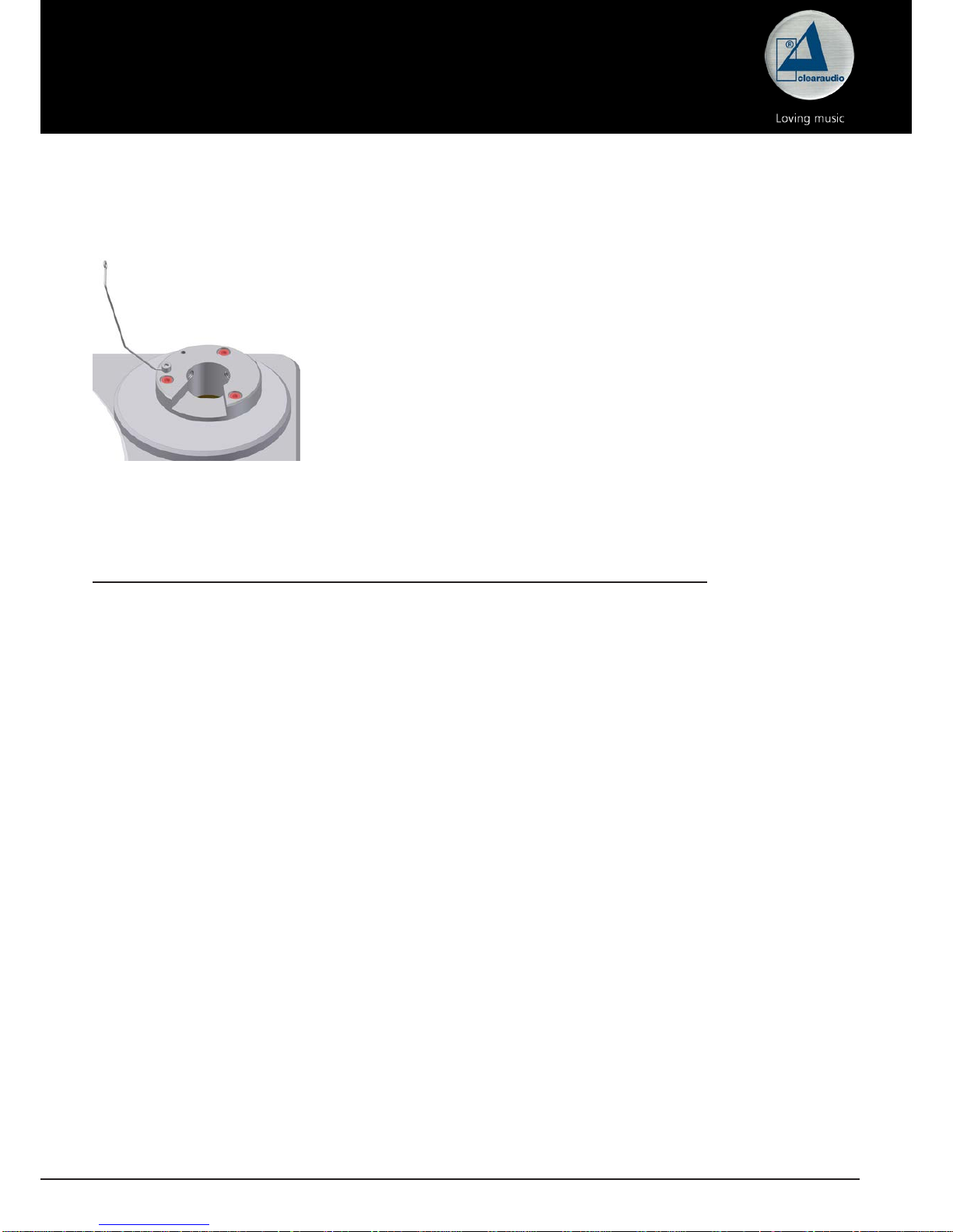
1. Mount the tonearm base to the respective armboard.
Please use the delivered screws.
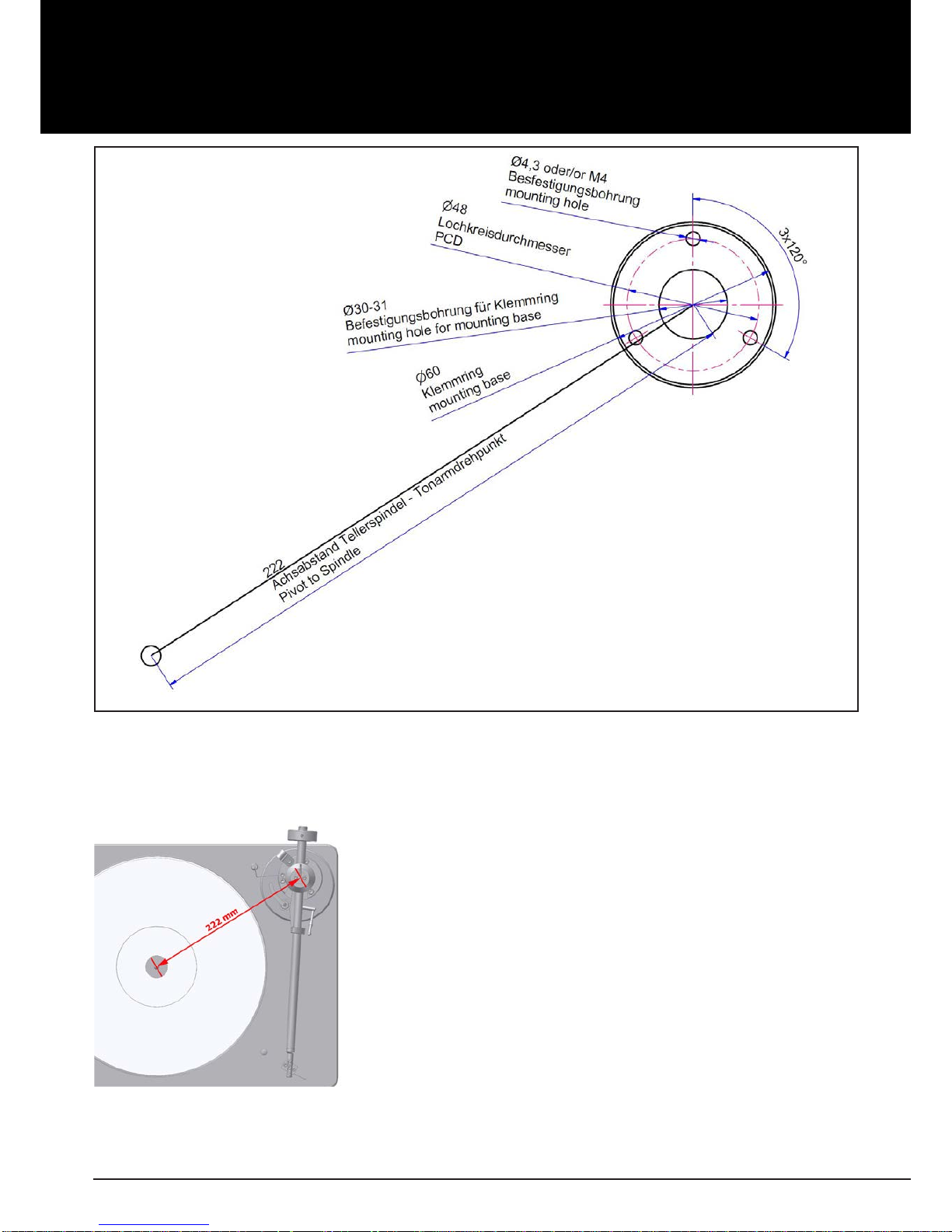
Mounting the aluminum clamping ring on a non-Clearaudio turntable:
To install the aluminum clamping ring on the turntable chassis, you will need to drill the required
holes. Please refer to the drilling template shown below (Picture 2) for the measurements to mark
the exact drilling holes.
Please be informed, that this drawing is not suitable for use as a mounting tool.
Use a 3.3 mm HSS drill bit, then cut an M4 thread into each hole using an appropriate tap cutting
tool.
If the turntable chassis material is not suitable for cutting threads, please use a 4.5 mm HSS drill bit
to drill the holes through the material. In this case use standard bolts and nuts to x the arm base.
Please note:
This drilling template is only for
Unify
9 inch tonearms. You will nd the the correct
pivot to spindle for
Unify
10, 12 and 14 inch in the technical data on page 10.
Pic. 1: Mount of
Unify
tonearm base
Page 6
User manual / Bedienungsanleitung
6 © clearaudio electronic GmbH, 2018/10
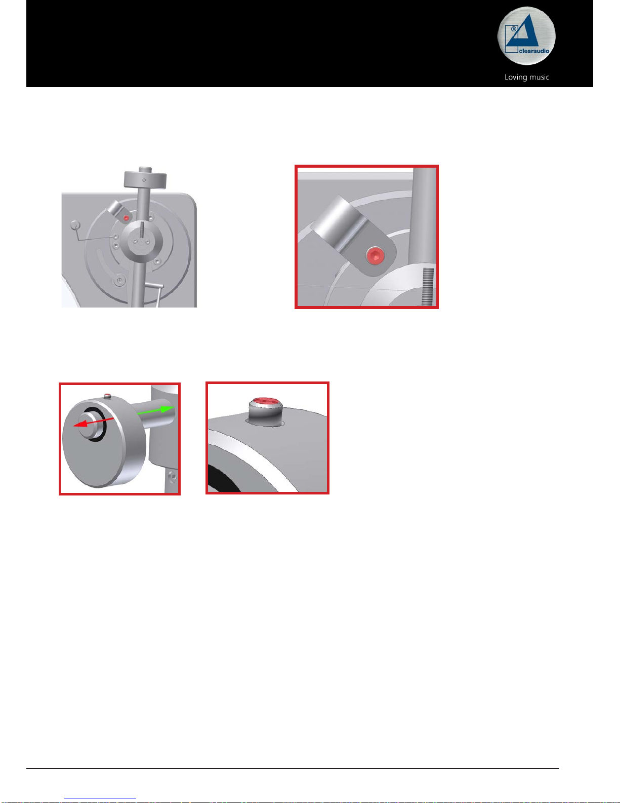
2. Make sure that the distance from the spindle to the pivot
point of the tonearm is exactly 222mm. When moving the
armboard in one or another direction you can locate the
correct armboard position.
Once located, tighten the screws of the armboard.
Pic. 3: Distance from spindle to the pivot (222 mm)
Pic. 2: Mounting the aluminum clamping ring on a non-Clearaudio turntable
Page 7
User manual / Bedienungsanleitung
Made in Germany 7
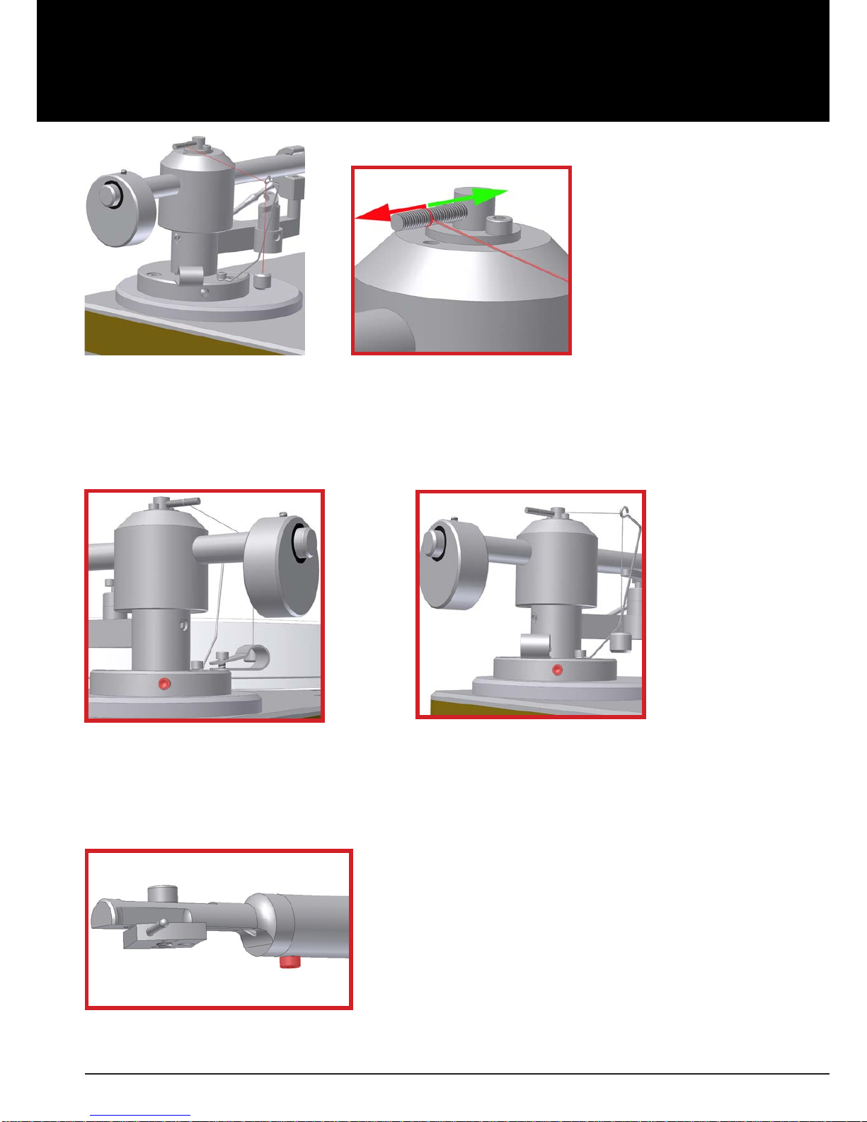
Pic. 4: Placing the arm tube to the pivot point
3. Carefully remove the security zip tie and unwrap the arm tube.
Caution: Once the security zip tie is removed pull it out of the armwand with reasonable care.
Now, place the arm tube on to the pivot point and lock it into it´s arm rest. Use the cable strain
relief screw and washer to secure the cable to the tonearm base.
Pic. 5: Detail: Cable strain relief screw
4. Slide the Clearaudio
Turbo Weight
on the shaft of the tonearm.
Lock the weight in it`s position by tighten the screw in the weight.
This is onlay a temporary position, the nal adjustment wll be done during cartridge installation.
Pic. 6:
Turbo Weight
5. Mount your cartridge according to the manufacturer´s instructions.
6. Use the Clearaudio
Weight Watcher
( Art.No. AC094) or the
Smart Stylus gauge
(Art.No.
AC089) to set tracking force (see cartridge instructions for recommended tracking force renge).
Adjusting tracking force is accomplished by moving the weight towards or away from the pivot
point on the shaft.
Note: When tightening the counterweight, insure that the weight is perfectly vertical otherwise
this may aect your cartridges azimuth settings.
7. Align cartridge for overhang and oset angle using the Clearaudio
Cartridge alignment gauge
(Art. No.AC005/IEC). Once done, re-check tracking force.
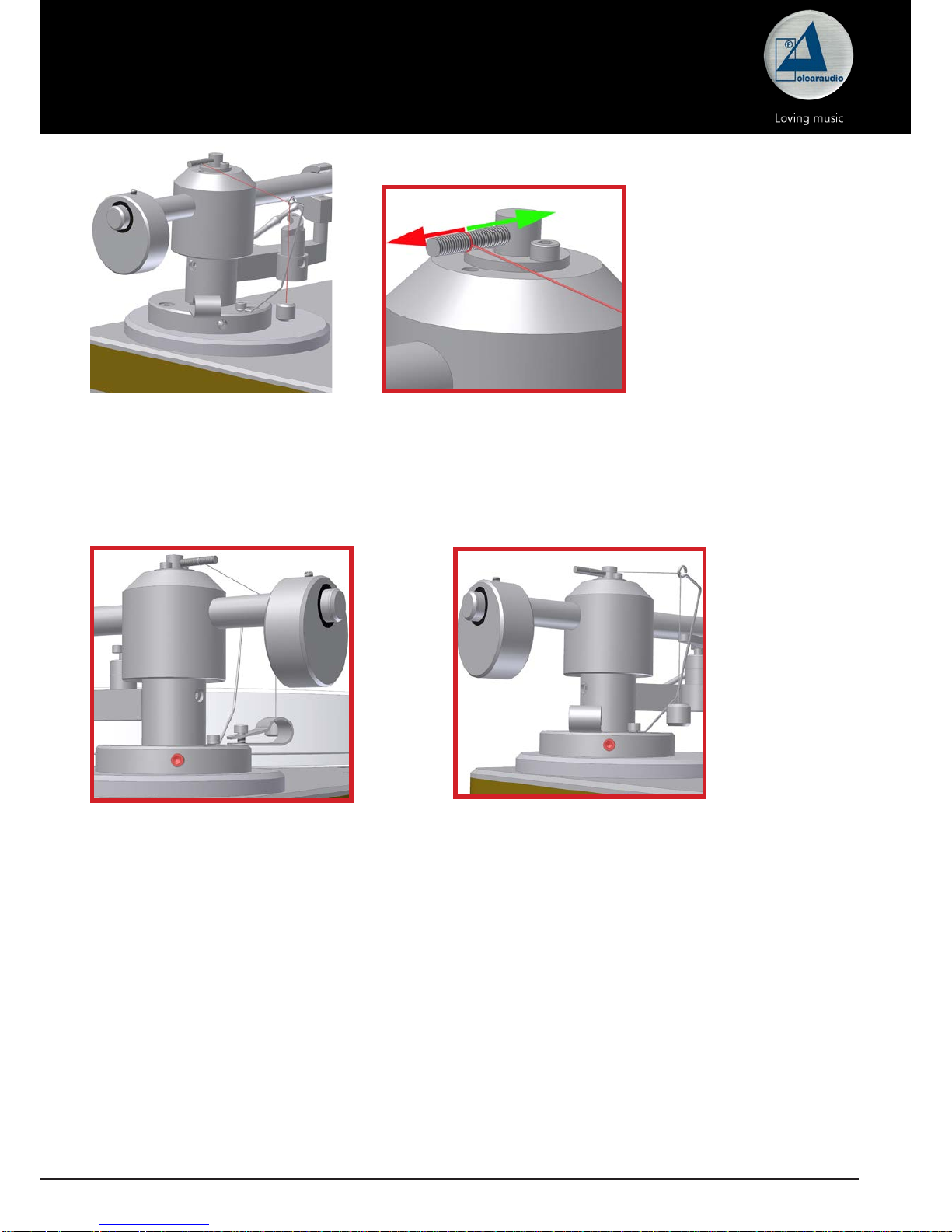
8. Feed the anti-skating weight through the anti-skating support wand and secure it to the threaded
shaft at the top of the tonearm bell. Note: Attaching the string to the position closes to the pivot
point is equal to approx. 0.5g of anti-skate. Each additional 1/8” out on the shaft will give you
another 0.5g of anti-skating force with a maximum of 3.0g if axed to the end of the shaft.
Page 8
User manual / Bedienungsanleitung
8 © clearaudio electronic GmbH, 2018/10
Pic. 9: Screw one for VTA
Please tighten both screws when nished and re-check tracking force after adjusting VTA.
Pic. 10: Screw one for VTA
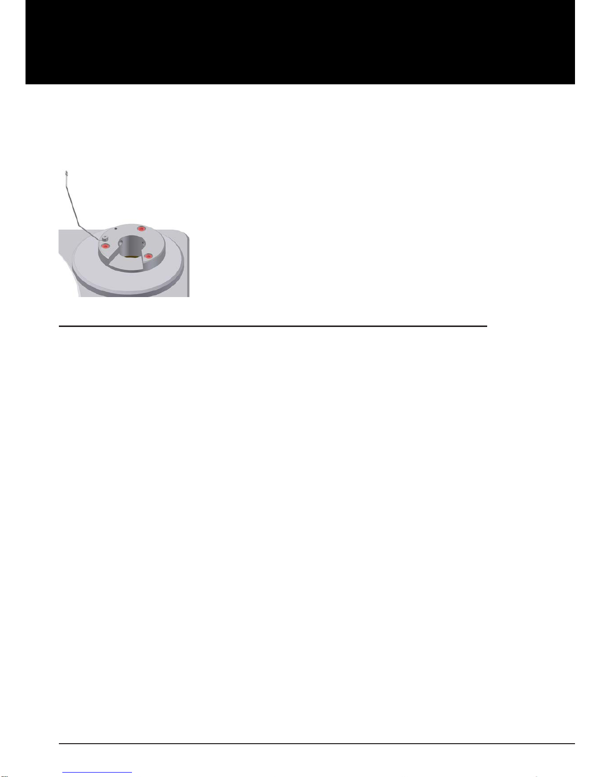
10. Azimuth adjustments are facilitated through the small allen screw on the bottom side of the
armwand where the headshell enters the carbon bre. Once you loosen this screw, you´ll be
able to rotate the headshell a small amount in either direction. Be sure to tighten the screw when
done.
Pic. 11: Allen screw on the bottom side of the armwand
Green arrowhead =
slower anti-skating
Red arrowhead =
stronger anti-skating
9. VTA adjustments are accomplished by loosening the two lock screws an the side of the armboard
base (approx. at the 10:00 and 2:00 positions). Once loosen, you can moove the arm up or down
to achieve the desired VTA.
Pic. 8: Placing the anti-skating weightPic. 7: Placing the anti-skating weight
Page 9

User manual / Bedienungsanleitung
Made in Germany 9
11. Listen to familiar recordings and make ne adjustments, as necessary, per cartridge manufacturers
instructions for best sound.
12. Please notice: Always move the mounted tonearm after you lift it up.
Attention:
Before the rst use or after a long storage, please apply the lift unit up and down
approximately 4-5 times, so that the oil inside can dissolve in order that the lift unit can
move smoothly.
3. Special notes
3.1 Maintenance
If you don`t use your
Unify
tonearm for a longer time, please move the tonearm lifter in regular
intervals. This avoid that the tonearm hang in a position when you listen to the music again.
6.2 Transportation
Should further transportation of the
Unify
tonearm be necessary, please alway use the original
packing material. Otherwise serious damage could occur.
6.3 Service
If any servicing or repair of a Clearaudio product is necessary, please rst contact your dealer or
distributor. Alternatively contact Clearaudio directly and we will advise you of your nearest service
location.
PLEASE RETAIN ALL ORIGINAL PACKAGING. You will need it if this product has to be transported
and/or shipped. Any further questions you may have about this product should be directed to your
local dealer or direct to Clearaudio.
Page 10

User manual / Bedienungsanleitung
10 © clearaudio electronic GmbH, 2018/10
4. Technical data
Procedure during installation:
1. Axis distance check or adjustments
2. Installation of the overhang
3. Use one of the zero touch points, to adjust the cartridge on the record centre point.
4. Skating force including modulation of a radius of 133 mm or 83.9 mm, through anti-skating to be
compensated.
9 inch 10 inch 12 inch 14 inch
Construction
details:
One point saphire
bearing, carbon bre
(black or silver) /
stainless steel
construction, incl.
Unify mount base.
One point saphire
bearing, carbon bre
(black or silver) /
stainless steel
construction, incl.
Unify mount base.
One point saphire
bearing, carbon bre
(black or silver) /
stainless steel
construction, incl.
Unify mount base.
One point saphire
bearing, carbon bre
(black or silver) /
stainless steel
construction, incl.
Unify mount base.
Cartridge balance
range:
2.5 gram – 17 gram 2.5 gram – 17 gram 2.5 gram – 17 gram 2.5 gram – 17 gram
Null points: Inner: 66.04
Outer: 120.9
Inner: 66.04
Outer: 120.9
Inner: 66.04
Outer: 120.9
Inner: 66.04
Outer: 120.9
Overhang: 17.3mm 15.48mm 12.9mm 12.4mm
Wiring: Clearaudio Sixtream
Super Wire (1.1m)
terminated with RCA
connector
Clearaudio Sixtream
Super Wire (1.1m)
terminated with RCA
connector
Clearaudio Sixtream
Super Wire (1.1m)
terminated with RCA
connector
Clearaudio Sixtream
Super Wire (1.1m)
terminated with RCA
connector
Distance from
pivot to stylus:
222mm 249.97mm 304mm 327mm
Oset angle: 25.54° 20.61° 17.16° 16.00°
Maximum of tilt
angle according to
the radius:
0.123°/cm 0.109°/cm 0.089°/cm 0.083°/cm
Middle skatingfactor at a radius of
133 mm and 83.9
mm:
0.49 0.41 0.36 0.33
Eective Tonearm
length:
9.4 inches
(exact 239.3mm)
10 inches
(exact 265.45mm)
12.5 inches
(exact 316.9mm)
13.4 inches
(exact 339.4mm)
Overall length: 300mm 335mm 390mm 420mm
Mounting style: Clearaudio
(diameter of bore
24.85 mm)
Clearaudio
(diameter of bore
24.85 mm)
Clearaudio
(diameter of bore
24.85 mm)
Clearaudio
(diameter of bore
24.85 mm)
Weight: approx. 772g
(incl. counterweight)
approx. 772g
(incl. counterweight)
approx. 772g
(incl. counterweight)
approx. 772g
(incl. counterweight)
Warranty: 3 years* 3 years* 3 years* 3 years*
* Provided that the warranty card is correctly completed and returned to Clearaudio within 14 days of purchase.
Clearaudio electronic is not responsible for typographical errors in descriptions.
Technical specications subject to change or improvement without prior notice.
Product availability is as long as stock lasts.
Copies and reprints of this documents, including extracts, require written consent from
Clearaudio electronic GmbH; Germany
Page 11
User manual / Bedienungsanleitung
Made in Germany 11
Sehr verehrte clearaudio – Kundin, sehr verehrter clearaudio – Kunde,
Höchste Ansprüche und Made in Germany, kombiniert mit Technologie und einem zeitlosem Design
lassen bestmöglichen High End Musikgenuss zu einem unschlagbaren Preis wahr werden!
Sie haben mit dem
Unify
Tonarm eines der besten Produkte seiner Art erworben.
Um alle Vorteile des
Unify
Tonarms nutzen zu können, lesen Sie bitte diese Bedienungsanleitung
aufmerksam durch. Alle Hinweise dienen dem Ausschöpfen der vollen Klangeigenschaften und
bewahren Sie vor Fehlbedienungen.
Wir wünschen Ihnen viel Freude mit Ihrem neuen clearaudio
Unify
Tonarm.
clearaudio electronic GmbH
Warnung
Das Gerät nicht Regen oder Feuchtigkeit aussetzen.
Das Netzkabel nicht mit feuchten oder nassen Händen anfassen.
Es dürfen keine Gegenstände mit oener Flamme, wie etwa brennende Kerzen, auf dem Gerät
aufgestellt werden.
Nur zur Nutzung auf Plattenspieler.
CE-MARKIERUNG
Page 12

User manual / Bedienungsanleitung
12 © clearaudio electronic GmbH, 2018/10
Inhaltsverzeichnis
1. Lieferumfang ................................................................13
2. Montage des
Unify
Tonarmes .......................................14 - 18
3. Besondere Hinweise .....................................................18
4. Technische Daten .........................................................19
Garantie ...........................................................................20 - 21
Page 13

User manual / Bedienungsanleitung
Made in Germany 13
1. Lieferumfang
Der clearaudio
Unify
Tonarm wird in einer speziellen Verpackung geliefert, um einen sicheren
Transport zu gewährleisten.
Bitte kontrollieren Sie den Inhalt nach unten beschriebener Auistung (Ziern 1. bis 10.)
Bitte heben Sie die Verpackung für Transportzwecke unbedingt auf.
1.
Unify
Carbon Tonarm mit clearaudio
Sixstream Super Wire
6. Antiskatinggewicht
2.
Unify
Tonarmbasis 7. 4 x Inbusschraube M 4x10 mm mit V2A
Beilagscheibe zur Befestigung der Kabelführung an der Tonarmbasis
3. clearaudio Turbo Weight 8. Inbusschraube M 3x10 mm mit V2A
Beilagscheibe (bei Benutzung des
Zusatzgewichts) für Headshell
4. Innensechskantschlüssel
1x 2,5 mm
1x 3 mm
9. Einstellschablone
5. Zusatzgewicht (für Tonabnehmer mit
geringem Eigengewicht)
10. clearaudio Bedienungsanleitung, Garantie
– und Qualitätskarte, Rücklieferschein
Empfohlene Hilfsmittel:
• clearaudio Cartridge alignment gauge (Art. Nr. AC005/IEC)
• clearaudio Weight Watcher (Art. Nr. AC094)
Diese und viele andere Zubehörartikel sind auch über unseren Onlineshop www.analogshop.de
erhätlich.
Page 14
User manual / Bedienungsanleitung
14 © clearaudio electronic GmbH, 2018/10
2. Montage des
Unify
Tonarmes
Bitte beachten Sie, dass diese Montageanleitung zur Installation des
Unify
nur für clearaudio
Plattenspieler gilt.
Bild 1: Montage der Tonarmbasis
1. Bei der Montage der Tonarmbasis auf einer Champion - Basis,
benutzen Sie bitte die kurzen Schrauben (Zubehör: Nr. 7).
Bei der Montage auf allen anderen Basen (clearaudio oder
Fremdfabrikaten) benutzen Sie bitte die empfohlene Schrauben
des jeweiligen Herstellers.
Montage der Aluminium-Klemmbasis auf einem Laufwerk anderer Hersteller:
Um die Aluminium-Klemmbasis auf dem Laufwerkchassis anbringen zu können, müssen erst
die Bohrungen zur Befestigung angebracht werden. Die Maße zum Anzeichnen der exakten
Bohrlochabstände entnehmen Sie bitte der unten abgebildeten Bohrschablone (siehe Abb. 2 ).
Bitte beachten Sie, dass diese Abbildung nicht maßstabsgetreu ist.
Verwenden sie für die Bohrungen einen 3,3 mm HSS- Spiralbohrer. Anschließend schneiden Sie in die
Bohrungen mit einem Gewindebohrer jeweils M4-Gewinde.
Ist das Material das Laufwerkchassis nicht dazu geeignet, es mit Gewinden zu versehen, verwenden
Sie bitte einen 4,5 mm HSS-Spiralbohr er, um die Bohrungen durch das Material zu bohren. In diesem
Fall können Sie den Klemmring mit handelsüblichen Schrauben in der entsprechenden Länge und
den dazu passenden Muttern befestigen (V2A-Inbus).
Bitte beachten:
Diese Bohrschablone ist nur für
Unify
9 Zoll Tonarm geeignet.
Den korrekten Achsabstand Tellerspindel zu Tonarmdrehpunkt für
Unify
10, 12 und 14
entnehmen Sie bitte den technischen Daten auf Seite 19.
Page 15

User manual / Bedienungsanleitung
Made in Germany 15
Bild 3: Abstand der Spindel zum Drehpunkt
2. Zur exakten Einstellung des Drehpunktes des Tonarms
empfehlen wir die clearaudio Drehtonarm-Einstellschablone
(AC005)! Dabei müssen Sie darauf achten, dass der Abstand
der Spindel zum Drehpunkt des Tonarms exakt 222 mm (für
9 Zoll Tonarme) betragen muss!
Den Abstand können Sie durch Drehen der Tonarmbasis
einstellen. Bitte schrauben Sie die Tonarmbasis nach
Verändern des Abstands wieder fest.
Bild. 2: Montage der Klemmbasis auf einem Laufwerk anderer Hersteller
Page 16

User manual / Bedienungsanleitung
16 © clearaudio electronic GmbH, 2018/10
4. Nun setzen Sie bitte die Tonarmglocke vorsichtig auf den Dorn der Tonarmbasis auf.
Achten Sie bitte darauf, dass Sie dabei kein Kabel knicken oder einklemmen.
5. Setzen Sie das Turbo Weight (Gegengewicht) auf das Tonarmrohr.
Stellen Sie das Auagegewicht des Tonabnehmers durch Verschieben des Gegengewichtes nach
vorne oder hinten ein.
Bitte beachten Sie bei der Fixierung des Gewichtes (nach der Gewichtseinstellung), dass dieses
vertikal ausgerichtet ist, andernfalls könnte der Azimuth des Tonabnehmers (vertikale Stellung
des Tonabnehmers) nicht korrekt sein!
Die Folge der Fehleinstellung wäre eine ungleiche Abtastung der Rillenlaufbahn.
Bild 6:
Turbo Weight
6. Fädeln Sie das Ende des Antiskating-Gewichts durch die Führungsöse und führen die Schlaufe
über den Gewindestab oberhalb der Tonarmglocke!
Bitte beachten: Die Position unmittelbar an der Tonarmglocke entspricht einer Antiskatingkraft
von 0,5 Gramm.
Je fünf weitere Rillen (nach außen) entsprechen ca. 0,5 Gramm.
Exakte Einstellsicherheit bietet allerdings nur die Benutzung einer Testplatte zur Überprüfung.
Bild 4: Befestigung der Kabelführung an der
Tonarmbasis
3. Bitte entfernen Sie vorsichtig den Klebestreifen (Transportsicherung). Beachten Sie bitte, dass
das Kabel darüber hinaus nicht gesichert ist, deshalb sollten Sie es mit einer Hand festhalten,
damit die dünnen Signalkabel nicht abreißen können! Befestigen Sie die Kabelführung an der
Tonarmbasis. Benutzen Sie hierfür die mitgelieferten Schrauben (Zubehör Nr.7).
Tipp: Am einfachsten ist es, den Tonarm vorsichtig auf dem Plattenteller abzulegen!
(Legen Sie vorher ein Tuch auf den Plattenteller, damit dieser nicht verkratzt wird!)
Bild 5: Schraube zur Befestigung der
Kabelführung
Page 17
User manual / Bedienungsanleitung
Made in Germany 17
Green arrowhead =
slower anti-skating
Red arrowhead =
stronger anti-skating
Bild 8: Antiskating-EinstellungBild 7: Antiskating Einstellung
Bild 9: Justierschraube eins
7. Zum richtigen Einstellen der Höhe Ihres Tonarms lösen Sie bitte beide Justierschrauben am
Fuß der Tonarmbasis; diese benden sich seitlich in einer Vertiefung und können mit dem
Innensechskantschlüssel (4) gelöst und nach der Höheneinstellung wieder angezogen werden!
Bei aufgelegter LP sollte der Arm parallel zur LP-Oberäche ausgerichtet sein.
Bild 10: Justierschraube zwei
8. Bitte beachten Sie, dass der Azimuth bereits ab Werk genau eingestellt wurde. Falls der Azimuth
dennoch verändert werden muss, um Geometriefehler eines Tonabnehmers zu kompensieren,
verfahren Sie bitte wie folgt: Lösen Sie die Schraube auf der Unterseite des Tonarmrohrs nahe
des Headshells. Jetzt können Sie den Azimuth durch Drehen des Headshells im Tonarmrohr
verstellen.
Page 18

User manual / Bedienungsanleitung
18 © clearaudio electronic GmbH, 2018/10
3. Besondere Hinweise
3.1 Wartung
Falls Sie Ihren clearaudio
Unify
Tonarm längere Zeit nicht benutzen, empfehlen wir Ihnen den
T onarmlift in regelmäßigen Abständen zu bewegen, um das Lagerfett geschmeidig zu halten und ein
mögliches Haken des Tonarms beim Abspielen zu vermeiden.
6.2 Transport
Sollte ein weiterer Transport des
Unify
erforderlich sein, verwenden Sie immer nur die
Originalverpackung. Andernfalls könnte Ihr Tonarm ernsthafte Schäden davon tragen.
6.3 Pege
Wenn eine Wartung oder Reparatur an einem clearaudio Produkt erforderlich ist, wenden Sie sich
bitte zuerst immer an Ihren Händler oder V ertriebspartner. Alternativ können Sie clearaudio direkt
kontaktieren und wir werden Sie von Ihrer nächstgelegenen Servicestelle beraten.
Bewahren Sie die vollständige Originalverpackung auf. Sie benötigen diese, wenn das Produkt
transportiert und / oder verschickt werden soll. Alle weiteren Fragen zu diesem Produkt können Sie
an ihren örtlichen Fachhändler oder direkt an clearaudio richten.
Bild 11: Azimuth-Einstellung nach Lösen Schraube auf der Unterseite des Tonarmrohrs
9. Montieren und justieren Sie Ihren Tonabnehmer nach Anleitung des jeweiligen Herstellers!
Bitte beachten Sie, dass Sie bei der Montage des Tonabnehmers immer den Nadelschutz auf
dem Tonträgersystem belassen.
10. Bitte beachten: bewegen Sie den fertig montierten Tonarm nur, nachdem Sie ihn mittels
Tonarmlifter angehoben haben!
Wichtig:
Vor dem erstmaligen Benutzen oder nach längerem Stillstand müssen Sie den Lift
ca. 4-5 x betätigen, damit sich das Fett im Tonarmlift lösen kann und die Liftbank
gleichmäßig und ordnungsgemäß abgesenkt werden kann.
Page 19

User manual / Bedienungsanleitung
Made in Germany 19
4. Technische Daten
Vorgehensweise bei der Einstellung:
1. Achsabstand überprüfen/einstellen
2. Überhang einstellen
3. Bei einem der beiden Nulldurchgangsradien radiale Ausrichtung des Tonkopfes auf den Plattenmittelpunkt
einstellen.
4. Skatingkraft mit Modulation bei Radius 133 mm oder 83,9 mm per Antiskating kompensieren
9 Zoll 10 Zoll 12 Zoll 14 Zoll
Konstruktionsprinzip:
Einpunkt Saphir
Lager, inkl. Basis,
Carbonber-
Tonarmrohr in
schwarz oder silber
Einpunkt Saphir
Lager, inkl. Basis,
Carbonber-
Tonarmrohr in
schwarz oder silber
Einpunkt Saphir
Lager, inkl. Basis,
Carbonber-
Tonarmrohr in
schwarz oder silber
Einpunkt Saphir
Lager, inkl. Basis,
Carbonber-
Tonarmrohr in
schwarz oder silber
Justierbare Tonabnehmer:
2,5 g – 17 g 2,5 g – 17 g 2,5 g – 17 g 2,5 g – 17 g
Nullpunkte: Innerer: 66,04
Äußerer: 120,9
Innerer: 66,04
Äußerer: 120,9
Innerer: 66,04
Äußerer: 120,9
Innerer: 66,04
Äußerer: 120,9
Überhang: 17,31 mm 15,48 mm 15,48 mm 12,4 mm
Signalkabel: clearaudio Sixtream
Super Wire (1,1 m)
konfektioniert mit
MPC Cinch Steckern
clearaudio Sixtream
Super Wire (1,1 m)
konfektioniert mit
MPC Cinch Steckern
clearaudio Sixtream
Super Wire (1,1 m)
konfektioniert mit
MPC Cinch Steckern
clearaudio Sixtream
Super Wire (1,1 m)
konfektioniert mit
MPC Cinch Steckern
Abstand (Mitte
Tonarmlager zu
Mitte Tellerlager):
222 mm 249,97 mm 304 mm 327 mm
Kröpfungswinkel: 25,54 ° 20,61 ° 17,16 ° 16,00 °
Abs. Maximum des
Fehlwinkels Bezogen auf Radius:
0,123 °/cm 0,109 °/cm 0,089 °/cm 0,083 °/cm
Mittlerer Skatingfaktor bei Radien
133 mm und 83.9
mm:
0,49 0,41 0,36 0,33
Eektive Tonarmlänge:
239,3 mm 265,45 mm 316,9 mm 339,4 mm
Gesamtlänge: 300 mm 335 mm 390 mm 420 mm
Tonarmaufnahme-
bohrung:
clearaudio
(Bohrungsdurchmesser: 24,85 mm)
clearaudio
(Bohrungsdurchmesser: 24,85 mm)
clearaudio
(Bohrungsdurchmesser: 24,85 mm)
clearaudio
(Bohrungsdurchmesser: 24,85 mm)
Gewicht: ca. 772 g
(inkl. Gegengewicht)
ca. 772 g
(inkl. Gegengewicht)
ca. 772 g
(inkl. Gegengewicht)
ca. 772 g
(inkl. Gegengewicht)
Garantie: 3 Jahre* 3 Jahre* 3 Jahre* 3 Jahre*
* Nur bei korrekt ausgefüllter und eingesandter Garantiekarte an clearaudio innerhalb von 14 Tagen.
Änderungen bleiben vorbehalten. Lieferbar solange Vorrat reicht. Für Druckfehler keine Haftung.
Irrtümer vorbehalten- Kopien und Abdrucke – auch nur auszugsweise – bedürfen der schriftlichen
Genehmigung durch die clearaudio electronic GmbH.
Page 20

User manual / Bedienungsanleitung
20 © clearaudio electronic GmbH, 2018/10
T o achieve the full Clearaudio warranty, it is necessary that you ll out and send the corresponding part of the warranty
registration certicate /card back to Clearaudio, within two weeks after purchase. Only if the product is returned in it’ s
original packing Clearaudio can provide the warranty of 2 years for the
Unify
tonearm .
Um die volle clearaudio Garantie in Anspruch nehmen zu können, senden Sie uns bitte die beigelegte Garantiekarte
innerhalb von zwei Wochen korrekt und vollständig ausgefüllt zu, da sonst nur die gesetzliche Gewährleistung berücksichtigt
werden kann. Nur bei Verwendung der Original- Verpackung während einer Rücksendung kann clearaudio die vollen 2
Jahre Garantie auf den
Unify
Tonarm geben.
ENGLISH
WARRANTY
For warranty information, contact your local Clearaudio distributor.
RETAIN YOUR PURCHASE RECEIPT
Your purchase r eceipt is y our permanent r ecor d of a valuable purchase. It should be kept in a safe place to be referred
to as necessary for insurance purposes or when corresponding with Clearaudio.
IMPORTANT
When seeking warranty service, it is the responsibility of the consumer to establish proof and date of purchase.
Your purchase receipt or invoice is adequate for such proof.
FOR U.K. ONLY
This undertaking is in addition to a consumer‘s statutory rights and does not aect those rights in any way.
FRANÇAIS
GARANTIE
Pour des informations sur la garantie, contacter le distributeur local Clearaudio.
CONSERVER L‘ATTESTATION D‘ACHAT
L‘attestation d‘achat est la preuve permanente d‘un achat de valeur. La conserver en lieu sur pour s‘y reporter aux ns
d‘obtention d‘une couverture d‘assurance ou dansle cadre de correspondances avec Clearaudio.
IMPORTANT
Pour l‘obtention d‘un service couvert par la garantie, il incombe au client d‘établir la preuve de l‘achat et d‘en corr oborer
la date. Le reçu ou la facture constituent des preuves susantes.
DEUTSCH
GARANTIE
Bei Garantiefragen wenden Sie sich bitte zunächst an Ihren Clearaudio Händler. Heben Sie Ihren Kaufbeleg gut auf.
WICHTIG!
Die Angaben auf Ihrer Quittung erlauben uns die Identizierung Ihres Gerätes und belegen mit dem Kaufdatum die
Dauer Ihrer Garantie-Ansprüche. Für Serviceleistungen benötigen wir stets die Gerätenummer. Diese nden Sie auf dem
Typenschild auf der Rückseite des Gerätes oder auch in der beigefügten Garantie-Registrierkarte.
NEDERLANDS
GARANTIE
V
oor inlichtingen omtrent garantie dient u zich tot uw plaatselijke Clearaudio.
UW KWITANTIE, KASSABON E.D. BEWAREN
Uw kwitantie, kassabon e.d. vormen uw bewijs van aankoop van een waardevol artikel en dienen op een veilige plaats
bewaard te worden voor evt, verwijzing bijv, in verbend met verzekering of bij correspondentie met Clearaudio.
BELANGRIJK
Bij een evt, beroep op de garantie is het de verantwoordelijkheid van de consument een gedateerd bewijs van aankoop
te tonen. Uw kassabon of factuurzijn voldoende bewijs.
Page 21

User manual / Bedienungsanleitung
Made in Germany 21
ITALIANO
GARANZIA
L’apparecchio è coperto da una garanzia di buon funzionamento della durata di un anno, o del periodo previsto dalla
legge, a partire dalla data di acquisto comprovata da un documento attestante il nominativo del Rivenditore e la data di
vendita. La garanzia sarà prestata con la sostituzione o la riparazione gratuita delle parti difettose.Non sono coperti da
garanzia difetti derivanti da uso improprio, errata installazione, manutenzione eettuata da personale non autorizzato
o, comunque, da circostanze che non possano riferirsi a difetti di funzionamento dell’apparecchio. Sono inoltre esclusi
dalla garanzia gli interventi inerenti l’installazione e l’allacciamento agli impianti di alimentazione.
Gli apparecchi verranno riparati presso i nostri Centri di Assistenza Autorizzati. Le spese ed i rischi di trasporto sono a
carico del cliente. La casa costruttrice declina ogni responsabilità per danni diretti o indiretti provocati dalla inosserv anza
delle prescrizio-ni di installazione, uso e manutenzione dettagliate nel presente manuale o per guasti dovuti ad uso
continuato a ni professionali.
ESPAÑOL
GARANTIA
Para obtener información acerca de la garantia póngase en contacto con su distribuidor Clearaudio.
GUARDE SU RECIBO DE COMPRA
Su recibo de compra es su prueba permanente de haber adquirido un aparato de valor, Este recibo deberá guardarlo
en un lugar seguro y utilizarlo como referencia cuando tenga que hacer uso del seguro o se ponga en contacto con
Clearaudio.
IMPORTANTE
Cuando solicite el servicio otorgado por la garantia el usuario tiene la responsabilidad de demonstrar cuándo efectuó la
compra. En este caso, su recibo de compra será la prueba apropiada.
Page 22

User manual / Bedienungsanleitung
22 © clearaudio electronic GmbH, 2018/10
Page 23

User manual / Bedienungsanleitung
Made in Germany 23
Page 24

clearaudio electronic GmbH
Spardorfer Straße 150
91054 Erlangen
Germany
Phone/Tel.: +49 9131 40300 100
Fax: +49 9131 40300 119
www.clearaudio.de
www.analogshop.de
info@clearaudio.de
Handmade in Germany
(Technische Änderungen vorbehalten -
Technical specication are subject to change without prior notication)
2018
© clearaudio electronic GmbH, 2018/10 Made in Germany
 Loading...