

Page 1
TTTT 33
TTaannggeennttiiaall ttoonneeaarrmm // TTaannggeennttiiaall TToonnaarrmm
Hi-Fi Components clearaudio
©
electronic GmbH
Spardorfer Str. 150 l D-91054 Erlangen l Tel. +49(0) 1805/059595 l FAX +49(0) 09131/51683
www.clearaudio.de l www.analogshop.de l info@clearaudio.de
/ copyright clearaudio 2012
User manual
Bedienungsanleitung
Version 1.5_30.10.12_E+D
TT 3
Page 2
TT 3
User manual / Bedienungsanleitung
Seite / Page 2 clearaudio electronic GmbH 2012
Dear audio enthusiast,
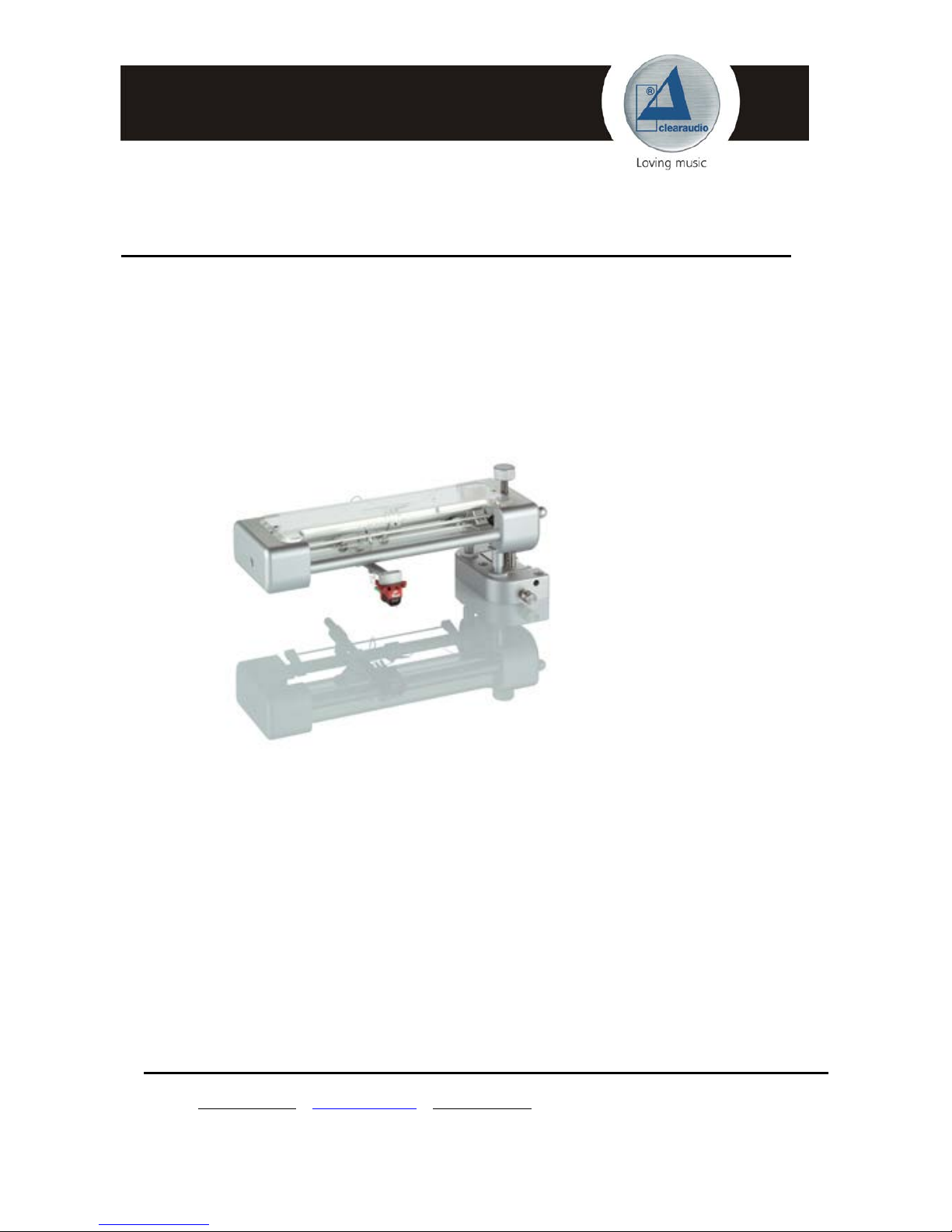
Congratulations ! You have purchased one of the best Tangential tonearm available in the
World of High-Fi.
Your clearaudio-
TT 3
tonearm has the capability to extract unprecedented performance
from absolutely ANY phono cartridge !
To achieve the full performance and to avoid any damages of this tonearm, please take the
time to get familiar with your clearaudio tonearm
TT 3
.
Your clearaudio
TT 3 -
tonearm will give you many years of musical enjoyment and
pleasure.
clearaudio electronic GmbH
CE-MARKING
COPYRIGHT
Recording and playback of any material may require consent. For further information refer to
the following:
- Copyright Act 1956
- Dramatic and Musical Performers Act 1958
- Performers Protection Acts 1963 and 1972
- Any subsequent statutory enactments and orders
Warnings
Do not expose the equipment to rain or moisture.
No naked flame sources, such as lighted candles, should be placed on the equipment.
Page 3

TT 3
User manual / Bedienungsanleitung
Seite / Page 3 clearaudio electronic GmbH 2012
User manual 3 - 13
Bedienungsanleitung 14 – 25
Contents
1. Scope of delivery 4
2. Mounting the tonearm base 5
3. TT 3 set - up 6
4. TT 3 adjustment 8
5. Special instructions / Service 12
6. Technical data 13
Warranty information 26
Page 4
TT 3
User manual / Bedienungsanleitung
Seite / Page 4 clearaudio electronic GmbH 2012
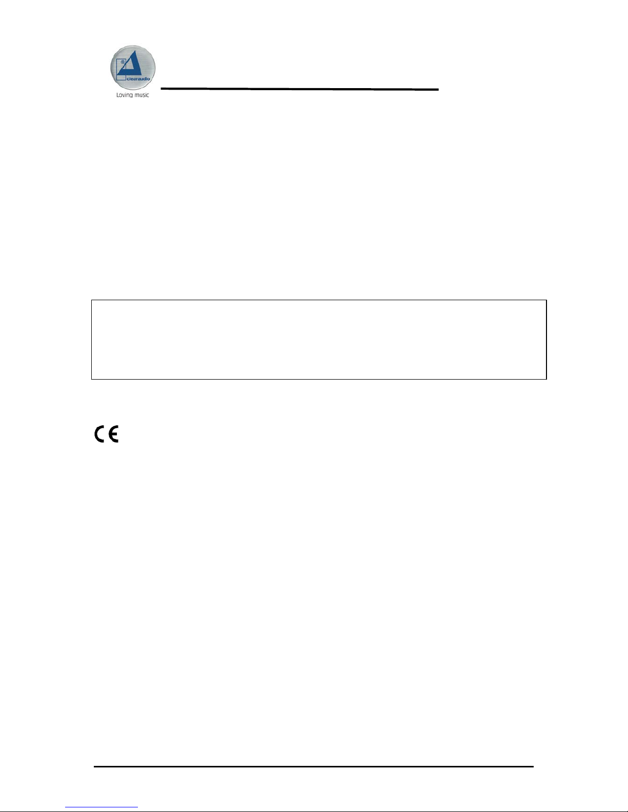
1. Scope of delivery
The clearaudio-
TT 3
tonearm is delivered in a special packing to ensure its safe transport.
Please check the contents as shown in the picture below.
Important note :
Please take special care of the tonearm cable while unpacking your clearaudio-
TT 3
tonearm !
Note: all windings are metrical !
Parts list:
1.
Tonearm
TT 3
complete assembled
6.
4 pcs. counterweights:
2.3g; 2.6g; 4.3g, 8.0 g
2.
2 a.
High-precision Dural-Aluminium tonearm base
Height adaptor
7.
Alignment gauge to adjust tangential
tracking
3.
1x Hex key wrench (# 1.5)
1 x Hex key wrench (# 2)
1x Hex key wrench (# 2.5)
1x Hex key wrench (# 3)
8.
Not shown: 1 pair of white gloves
4.
High-precision silver carbon fibre headshell
(without cartridge)
9.
Not shown: Warranty card, user manual,
clearaudio Quality Certificate and sales
return paper
5.
Screws for bases:
- 3x screws M4 x 25 (tonearm base)
- 3x screws M4 x 40 (height adaptor)
Screws for cartridges (no pic.):
- 2 x M2.5 x 12
- 2 x M2.5 x 14
Pic.1: Tonearm parts
1 2 6
7
2 a
5 3 4
Page 5
TT 3
User manual / Bedienungsanleitung
Seite / Page 5 clearaudio electronic GmbH 2012
Tonearmbase
Height adaptor
2. Mounting the tonearm base
Mounting the tonearm base on a clearaudio turntable:
Mount the tonearm base (see picture 2) with the three screws and the hex key wrench (#3)
onto the tonearm mounting platform.
Please tighten all three screws as shown in the picture below.
Pic.2: Mounting the tonearm base
Pic.3: Tighten the three screws
Page 6
TT 3
User manual / Bedienungsanleitung
Seite / Page 6 clearaudio electronic GmbH 2012
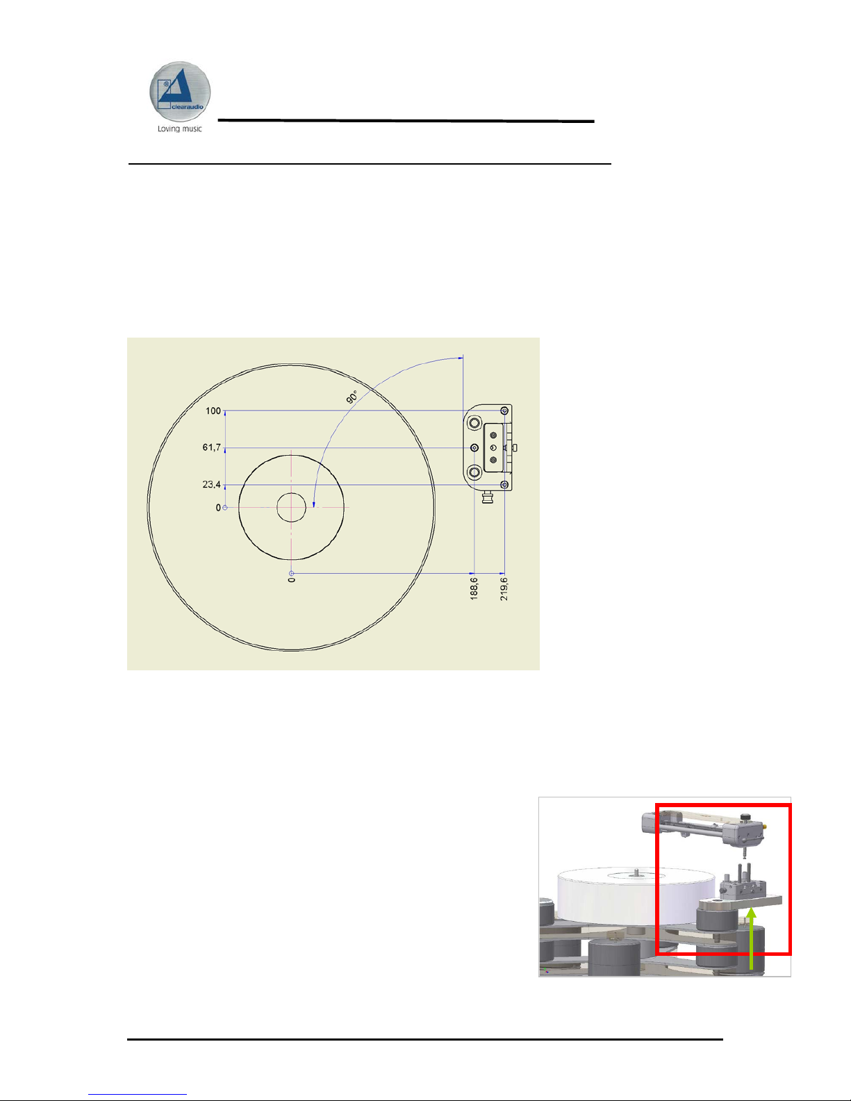
Mounting the tonearm base on a turntable of other manufacturers:
In order to mount the tonearm base on the turntable chassis please first drill three holes into
the turntable chassis. To find out the right position of these drills please take the
measurements out of the drawing template (see picture below). For this step use an 3,3 mm
drill. After you have drilled the three holes, cut the windings with a proper screw-tap. If the
material of the turntable chassis is not suitable to be fitted with windings please use an
4,5mm drill for the holes. In this case you will need some longer screws with nuts to fix the
tonearm base.
Now you can mount the tonearm base on the clean and dry surface of the turntable chassis.
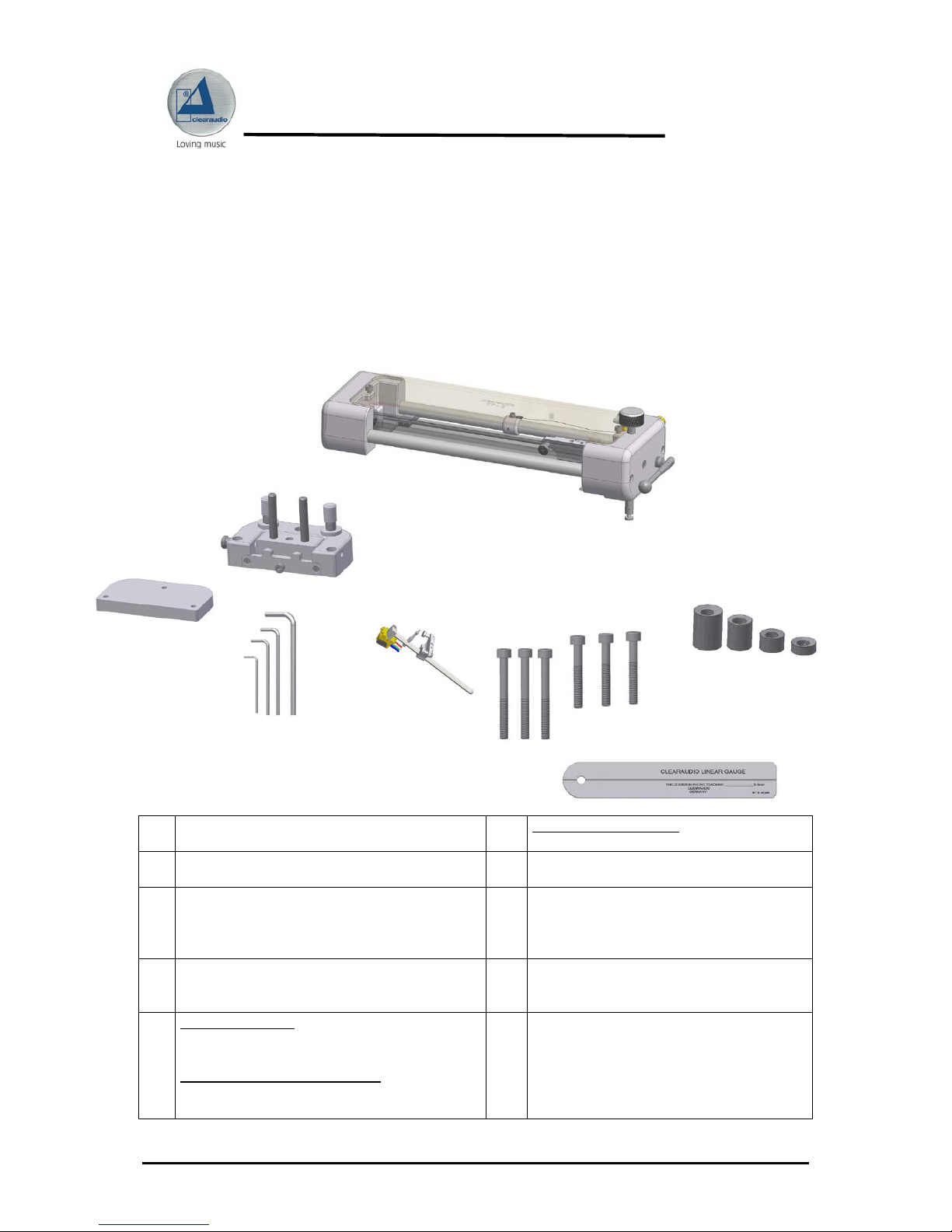
3. TT 3 set - up
For the next steps please remove the foam, that is used for transportation safety of the
tonearm carriage.
To place the tonearm it is required that the two rods of the
tonearm base are in vertical position. To achieve this, please
pull out the small pivot on the side of the tonearm base and
pull the two rods in the vertical position. Now you can slide
the tonearm with its two precise drills onto the two rods of
the base. Do this until the threaded bolt in the middle
between the two drills of the tonearm fully rests in the drilling
of the tonearm base.
Pic.5: Placing the tonearm on the tonearm base
Pic.4: Drilling template
Page 7
TT 3
User manual / Bedienungsanleitung
Seite / Page 7 clearaudio electronic GmbH 2012
Pic.8: To seize the screw
Pic.10: Correct position of the headshell
Pic.9: Turning the headshell back
Pic.8: Turning the headshell
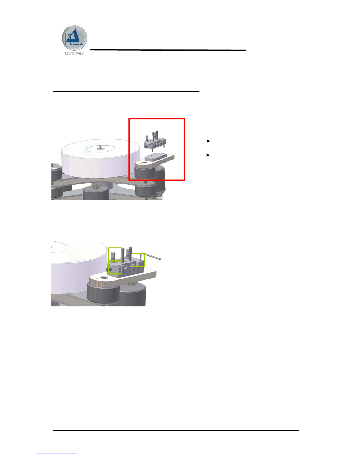
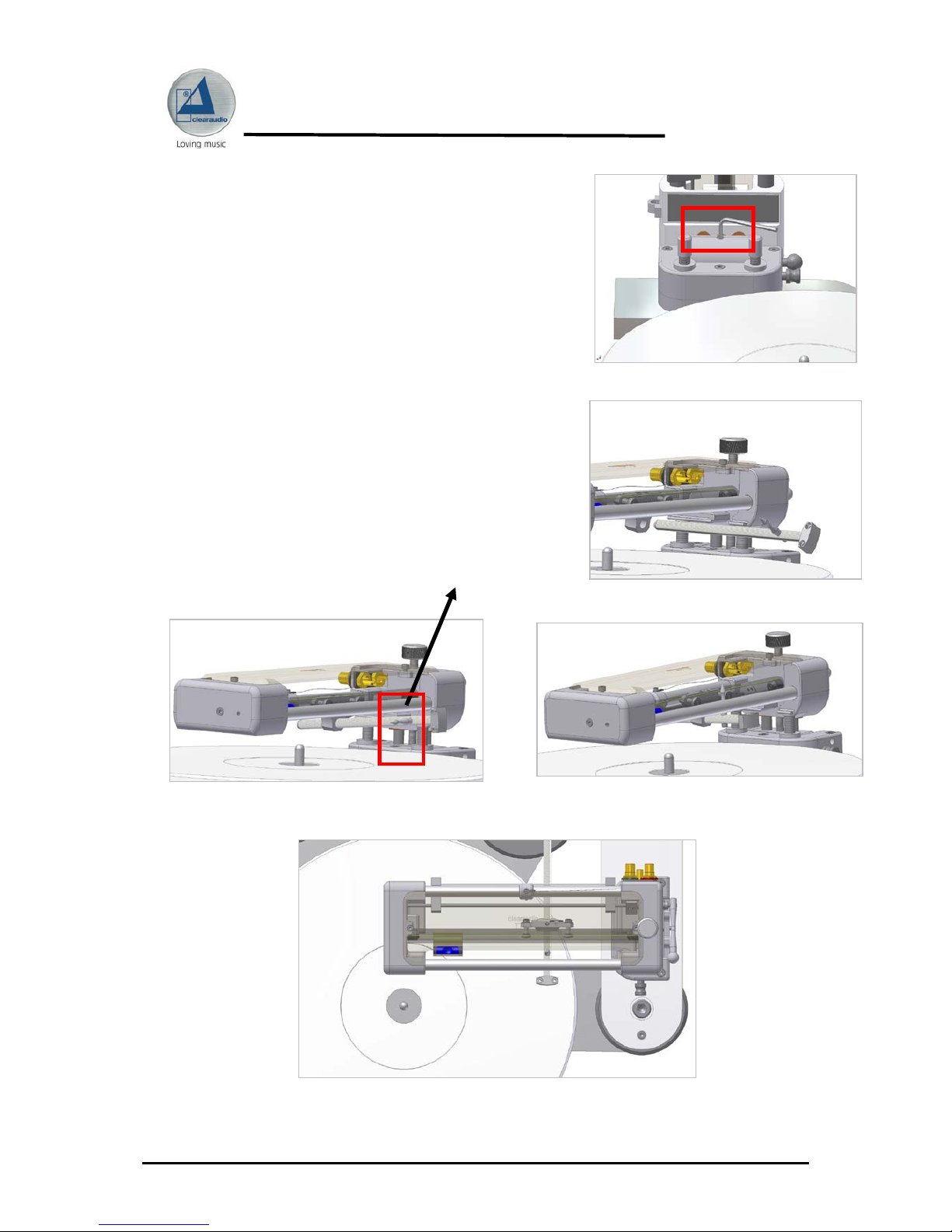
Tighten the screw of the tonearm base
as shown in picture 6.
For the next step please remove first all counterweights from
the headshell.
Slide the headshell through the proper drilling in the
carriage of the tonearm.
When sliding the headshell, turn the headshell
(as shown in pic. 8) so that the positioning shaft of the
headshell can pass the main rod of the tonearm.
After passing the first main rod, turn the headshell back (as
shown in pic. 9)
Positioning shaft
Pic.6: Tighten the VTA-assembly
Pic.7: Setting up the headshell
Page 8
TT 3
User manual / Bedienungsanleitung
Seite / Page 8 clearaudio electronic GmbH 2012
Pic.11: Locking the headshell
To tighten the headshell please move the carriage to the right side of the tonearm.
Lock the headshell in the carriage from above through the small hole in the top of the cover
plate by using the hex key wrench (#1,5) (Pic. 11).
4. TT 3 adjustment
4.1 Adjustment of the cartridge
The now following adjustment requires an already mounted cartridge on the headshell.
Therefore please follow the instructions in the users manual of the cartridge manufacture.
Please do not remove the needle protection of the cartridge!
Connect the pins of the tonearm cable with the corresponding pins of the cartridge.
Please take care of the colour codes.
Red: right channel / R+
Green: righ t channel / R-
White: left channel / L+
Blue: left channel / L-
Adjust little pressure. The exact pressure will be adjusted later
Page 9

TT 3
User manual / Bedienungsanleitung
Seite / Page 9 clearaudio electronic GmbH 2012
Pic.12: Setting up the counterweight(s)
Pic.13: Locking the counterweight(s)
Therefore take one or more counterweight(s) (depending on the weight of your cartridge)
and slide them onto the headshell as shown in picture 12. Adjust little stylus pressure, while
sliding the counterweight(s) in the direction of the cartridge.
Now lock the counterweight(s) by using the hex key wrench # 1,5.
It is easier, if the tonearm is in vertical position (as shown in picture 13).
4.2 VTA - adjustment
The following adjustment can be done with an old and used
record. This LP should be flat.
Instead of a record you can also use the delivered linear
tracking gauge.
Please unlock the screws on the side to change the height of
the tonearm. To achieve the right height of the cartridge you
can move the tonearm by turning the VTA screw on the top of
the tonearm
(shown in picture 14).
Pic.14: Height adjustment
Page 10

TT 3
User manual / Bedienungsanleitung
Seite / Page 10 clearaudio electronic GmbH 2012
Pic.16 a: Bubble level
Pic.16 b: Adjustment of the tonearm`s tilt angle
Pic.15: Adjustment of the tonearm
The carbon headshell tube should be parallel to the surface of the record (without needle
protection and cartridge lifted down record!).
To ensure a stable function mode of the tonearm, please
tighten the screws on the side of the tonearm (allen
wrench wrench # 2; see pic. 15).
To
Please unlock the screws to change the height of the
tonearm
tonearm.
The tonearm angle can be adjusted with the screw in the tonearm base (see pic. 16 b). The
tonearm angle is correct adjusted, if the bubble level is centered.
Adjust the correct stylus pressure as instructed in the cartridge´s user manual.
To achieve the exact stylus pressure we recommend the use of the clearaudio digital stylus
pressure gauge “Weight Watcher” (Art.-#: AC 094; also available at www.analogshop.de).
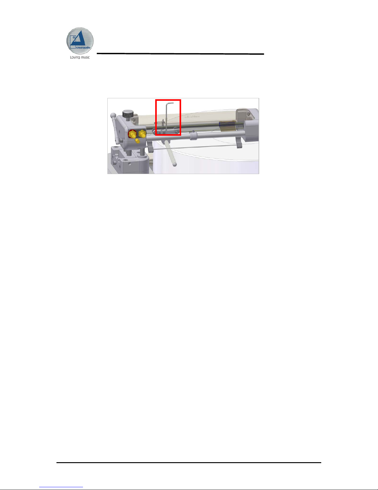
4.3 Adjustment of the Azimuth (vertical needle-position in the groove).
Please be very careful by the following steps:
Lift your cartridge up (!)
Take a straight bar or rod (e.g. hex key wrench) which
can be placed on the top of the cartridge.
Place this piece on top of the headshell as shown in the
picture 17 and secure it with an piece of adhesive tape.
a
b
a = b !
Pic.17. Adjustment of the Azimuth
Page 11

TT 3
User manual / Bedienungsanleitung
Seite / Page 11 clearaudio electronic GmbH 2012
Lift your cartridge down on the record or the linear gauge and make sure that the straight
bar or rod is parallel to the surface of the record or gauge. You will have to loosen the
screw in the carriage holding the headshell in order to change the horizontal position
(Azimuth) of the cartridge. Lock this screw again after your adjustments are finished.
The following step will ensure real linear tracking.
You will need the delivered clearaudio linear gauge for this adjustment.
Place the gauge over the spindle of the platter and turn it under the chassis of the tonearm.
Take special care on the cantilever of the cartridge!
Please remove the LP if used one before ! Place the cartridge down and position the
diamond on the black line of the gauge (see pic. 18 ; “red line”).
Do this step at the „beginning“ and also at the „end“ of the „record“ (imagine that there is
now one on your platter).
This adjustment is successful, if the diamond touches the black line in all positions.
To change the position of the diamond, please unlock the screw on the top of the carriage
with the hex key wrench No 2 and move the headshell forward or backward until the
diamond sits exact on the black line.
This adjustment is very important to ensure the real linear tracking ability of your
tonearm.
After this adjustment please check the azimuth of your cartridge again (see 4.3 / page: 9)
and adjust the recommend stylus pressure (see cartridge manufacturers user manual).
The clearaudio
TT 3
is now complete assembled and set up.
Pic.18: Adjustment of the linear tracking
Distance
between
diamond tip
and headshell
locking screw
is approx.
62 mm / 2,44
inch
Page 12

TT 3
User manual / Bedienungsanleitung
Seite / Page 12 clearaudio electronic GmbH 2012
5. Special Instructions / Service
Please take the time to fill out the enclosed warranty card and return it to clearaudio or
your local distributor / dealer.
If you do not return this card within 14 days after purchase the guarantee will
only be for the law regulated guarantee time period.
During any transportation of the tonearm, always protect the carriage with a piece of e.g.
foam so that the carriage is not able to move during transportation.
Please use for sending the original packaging.
If there is any damage to any parts of the tonearm that could influence exact tracking,
please contact your local dealer, distributor or clearaudio.
Use only special acrylic cleaner, which is not alc oho l b ased to clean the acrylic parts of the
tonearm. Otherwise you could damage the material (haircracks and spots on the
acrylic surface).
• Never put oil or any similar liquids on the glass tube or into the precision
bearings !
• Never move or readjust the screws in the carriage of the tonearm.
They are to be adjusted only by qualified dealers or at the clearaudio
factory.
• Keep your
TT 3 -
tonearm out of extreme temperature and extreme
moisture environments.
• The tonearm dust cover should be left on the arm during normal operation.
Always replace after making any adjustments or cleaning procedures.
clearaudio electronic GmbH,
Spardorfer Strasse. 150,
D-91054 Erlangen
Germany
Phone : +49-(0)9131/40 300 100
Phone : +49-(0)9131/51683
info@clearaudio.de
www.analogshop.de
www.clearaudio.de
Page 13

TT 3
User manual / Bedienungsanleitung
Seite / Page 13 clearaudio electronic GmbH 2012
6. Technical data
Construction
Resonance-optimized chassis, patented two-point -
tangential tracking
Drive
- Strictly mechanical
- Selected high precision ball bearings running in a
polished glass tube
Weight
Approx: 670 gram without base
base only approx. 235 gram
Dimensions (w x h x d) in inch:
Dimensions (w x h x d) in mm:
Approx: 10,3 inch x 2 inch x 4 inch
Approx: 260 mm x 50 mm x 100 mm
Warranty:
5 Years* (see chapter 5 / page 26)
* Only if the warranty card is filled out correctly and sent back to clearaudio within 14 days.
Clearaudio electronic is not responsible for typographical errors in descriptions. Technical
specifications subject to change or improvement without prior notice. Availability as long as stock
lasts. Copies and imprints- also only in extracts – require written conformation through clearaudio
electronic GmbH; Germany
clearaudio electronic GmbH 2012
Version: October 2012
Page 14

TT 3
User manual / Bedienungsanleitung
Seite / Page 14 clearaudio electronic GmbH 2012
Sehr verehrte clearaudio – Kundin, sehr verehrter clearaudio - Kunde,
Wir gratulieren Ihnen! Sie haben sich für einen der besten Tonarme, den neuen clearaudio
TT 3
- Tangentialtonarm entschieden. Ein erstklassiges, in aufwändiger Handarbeit gefertigtes
Produkt der clearaudio electronic GmbH.
Mit dem clearaudio
TT 3 -
Tangentialtonarm haben Sie die Möglichkeit, alle Fähigkeiten
Ihrer HiFi-Anlage in Verbindung mit einem adäquaten Tonabnehmersystem voll
auszuschöpfen!
Damit Sie die Wiedergabemöglichkeiten dieses einzigartigen Tangentialtonarms optimal
nutzen können, lesen Sie bitte diese Aufbau- und Bedienungsanleitung aufmerksam durch.
Sämtliche Hinweise dienen dazu, Ihnen viele Jahre ungetrübten Musikgenuss zu bereiten und
Fehlbedienungen zu verhindern.
Wir wünschen Ihnen viel Freude und Hörgenuss mit Ihrem neuen
clearaudio
TT 3 -
Tangentialtonarm.
clearaudio electronic GmbH
CE-MARKIERUNG
URHEBERRECHT
Aufnahme und Wiedergabe jeglichen Tonmaterials kann die Zustimmung des Urhebers
erfordern. Beachten Sie dazu folgende Informationsschriften.
- Copyright Act 1956 (Urheberrechtsgesetz 1956)
- Dramatic and Musical Performers Act 1958 (Gesetz über dramatische und musikalische
Aufführungsrechte, 1958)
- Performers Protection Acts 1963 and 1972 (Künstlerschutzgesetze von 1963 und 1972)
- Jegliche nachfolgende, gesetzliche Verfügungen und Bestimmungen.
WARNUNGEN
Das Gerät nicht Regen oder Feuchtigkeit aussetzen.
Das Netzkabel nicht mit feuchten oder nassen Händen anfassen.
Es dürfen keine Gegenstände mit offener Flamme, wie etwa brennende Kerzen, auf dem
Gerät aufgestellt werden.
Page 15

TT 3
User manual / Bedienungsanleitung
Seite / Page 15 clearaudio electronic GmbH 2012
Inhaltsverzeichnis
1. Lieferumfang 16
2. Befestigung der Tonarmbasis 17
3. Aufsetzen des TT 3 - Tonarms 18
4. TT 3 Einstellungen 20
5. Wartung und besondere Hinweise 24
6. Technische Daten 25
Garantiebedingungen 26
Page 16

TT 3
User manual / Bedienungsanleitung
Seite / Page 16 clearaudio electronic GmbH 2012
1. Lieferumfang
Der clearaudio
TT 3
- Tangentialtonarm verlässt unsere Fertigung in einer besonders
sicheren und dem Tonarm angepasste Verpackung, die einen sicheren Transport garantiert.
Bitte bewahren Sie diese Verpackung für den Fall eines Transports auf.
Bitte kontrollieren Sie den Lieferumfang Ihres neu erworbenen clearaudio
TT 3
Tangentialtonarms.
Achten Sie vor der Entnahme des clearaudio
TT 3
– Tonarms aus seiner Verpackung auf
das empfindliche Signalkabel des Tonarms, dass Sie mit größtmöglicher Vorsicht behandeln
sollten.
Wichtig: alle Gewinde sind Rechtsgewinde (metrisch) !
1.
Tonarm
TT 3
; komplett vormontiert
6.
4 Stk. Gegengewichte:
2,3 gr.; 2,6 gr.; 4,3 gr. , 8,0 gr.
2.
2 a.
Dural-Aluminium Präzisionsbasis zur
Aufnahme des Tonarmes;
Höhen-Zwischenstück
7.
Einstellschablone zur Justage des tangentialen
Spurfehlwinkels
3.
1x Inbusschlüssel (# 1,5)
1 x Inbusschlüssel (# 2)
1x Inbusschlüssel (# 2,5)
1x Inbusschlüssel (# 3)
8.
Keine Abbildung: 1 Paar weiße Handschuhe
4.
Präzisionsgefertigtes Silber - Carbon -
Headshell
9.
Keine Abbildung: Garantiekarte,
Bedienungsanleitung, clearaudio Quality
Certificate, Rücklieferschein
5.
Schrauben für Tonarmbasis:
- 3 x Inbusschrauben M4x25 (Tonarmbasis)
- 3 x Inbusschrauben M4x40
Schrauben für Tonabnehmer (keine Abb.):
- 2 x M2,5 x 12
- 2 x M2,5 x 14
Abb.1: Lieferumfang
1 2 5 6 7
2 a
3
4
Page 17

TT 3
User manual / Bedienungsanleitung
Seite / Page 17 clearaudio electronic GmbH 2012
Tonarmbasis
Höhen-Zwischenstück
2. Befestigung der Tonarmbasis
Montage der Tonarmbasis auf einem clearaudio Laufwerk:
Befestigen Sie die Tonarmbasis auf dem sauberen Untergrund des Laufwerkchassis mit den
drei mitgelieferten Innensechskantschrauben (Siehe Abb. 2 unten) und dem passenden
Inbusschlüssel (Größe 3). Achten Sie auf passgenauen Sitz und planebene Montageflächen.
Bitten ziehen Sie alle drei Schrauben fest an (siehe Abbildung 3).
Abb.2: Befestigen der Tonarmbasis
Abb.3: Anziehen der Schrauben
Page 18

TT 3
User manual / Bedienungsanleitung
Seite / Page 18 clearaudio electronic GmbH 2012
Montage der Tonarmbasis auf einem Laufwerk anderer Hersteller:
Um die Tonarmbasis auf dem Laufwerkchassis anbringen zu können, müssen erst die
Bohrungen zur Tonarmbasisbasisbefestigung angebracht werden. Die Maße zum Anzeichnen
der exakten Bohrlochabstände entnehmen Sie bitte der unten abgebildeten Bohrschablone
(siehe Abb. 4). Verwenden Sie für die Bohrungen einen 3,3mm HSS-Spiralbohrer.
Anschließend schneiden Sie in die Bohrungen mit einem Gewindeschneider jeweils M4Gewinde. Ist das Material des Laufwerkchassis nicht dazu geeignet, es mit Gewinden zu
versehen, verwenden Sie bitte einen 4,5mm HSS-Spiralbohrer, um die Bohrungen durch das
Material zu setzen. In diesem Fall können Sie die Tonarmbasis mit handelsüblichen
Schrauben in der entsprechenden Länge und den dazu passenden Muttern befestigen (V2A –
Inbus).
3. Aufsetzen des TT 3 Tonarms
Bitte entfernen Sie zuerst den Schaumstoff, der als Transportsicherung für den Tonarm
angebracht wurde.
Zum Aufsetzen des Tonarmes ist es einfacher, wenn die
beiden Trägerstäbe der Tonarmbasis vertikal stehen. Dazu
ziehen Sie die Arretierungsstiftverriegelung an der
Tonarmbasis heraus, um das Gelenk in die vertikale Position
zu bringen. Setzen Sie nun den Tonarm mit den
Führungsbohrungen auf die Trägerstäbe der Tonarmbasis
auf und schieben Sie den Tonarm so weit auf die
Trägerstäbe, bis der mittlere Gewindestab vollständig in der
Bohrung des Tonarmbasis versinkt.
Abb.5: Aufsetzen des Tonarms
Abb.4: Bohrschablone
Page 19

TT 3
User manual / Bedienungsanleitung
Seite / Page 19 clearaudio electronic GmbH 2012
Abb.10: Korrekte Position des Headshells (Oben-Ansicht)
Abb.7: Einsetzen des Headshells
Ziehen Sie die Schrauben auf der Innenseite der
hochgeklappten Tonarmbasis fest (siehe Abbildung 6).
Bitte entfernen Sie für den nächsten Schritt alle Gegengewichte von ihrem Headshell.
Schieben Sie das Headshell durch die dafür vorgesehene
Durchgangsbohrung (siehe Abbildung 7).
Beim Durchschieben, drehen Sie das Headshell so (siehe
Abbildung 8), dass der Positionsstift die obere Tonarmstange
passiert.
Danach drehen Sie das Headshell wieder in die
Ausgangsposition (siehe Abbildung 9).
Abb. 6: Festschrauben der Basis
Abb.8: Position nach Einsetzen des Headshells
Abb.9: Position nach Einsetzen des Headshells
Positionsstift
Page 20

TT 3
User manual / Bedienungsanleitung
Seite / Page 20 clearaudio electronic GmbH 2012
Abb.11: Befestigen des Headshells
Um das Headshell zu befestigen, schieben Sie dieses zurück in Richtung der Tonarmbasis.
Durch die kleine Öffnung in der Abdeckplatte können Sie mit dem Inbusschlüssel (Nummer
1,5) das Headshell festschrauben (siehe Abbildung 11).
4. TT 3 Einstellungen
4.1 Justage des Tonabnehmers
Die folgende Einstellung der Tonarmhöhe erfordert die Montage des Tonabnehmersystems
auf dem Headshell. Befolgen Sie hierzu die Anweisungen des Tonabnehmer - Herstellers.
Bitte belassen Sie den Nadelschutz auf Ihrem Tonabnehmersystem !
Verbinden Sie anschließend die Pins des Signalkabels mit den Kontakten des
Tonabnehmersystems. Beachten Sie dabei folgende Farbcodierung:
Rot: rechter Kanal / R+
Grün: rechter Kanal / R-
Weiß: linker Kanal / L+
Blau: linker Kanal / L-
Setzen Sie den Tonabnehmer durch Betätigen des Lifthebels an der Seite des Tonarms
vorsichtig auf die LP oder die Einstellschablone auf.
Page 21

TT 3
User manual / Bedienungsanleitung
Seite / Page 21 clearaudio electronic GmbH 2012
Abb.12: Aufsetzen der Gegengewichte
Abb.13: Befestigen der Gegengewichte
Bitte stellen Sie nur grob die Auflagekraft des Tonabnehmers ein.
Die korrekte Einstellung erfolgt am Ende der Tonarmeinstellungen.
Nehmen Sie eines oder mehrere (abhängig von dem Gewicht Ihres Tonabnehmers) der vier
mitgelieferten Ausgleichsgewichte und stecken Sie diese(s) auf das Headshell (siehe
Abbildung 12).
Benutzen Sie zum Festziehen der Gewichte den Schlitzschraubendreher.
Für das Festziehen der Schrauben empfehlen wir den Tonarm wieder vertikal auszurichten
(siehe Abbildung 13).
4.2 VTA-Einstellung
Die Einstellarbeiten können unter Verwendung einer alten
LP durchgeführt werden. Besorgen Sie sich nach
Möglichkeit eine sehr plane, aber nicht zu dicke
Schallplatte. Falls Sie keine LP verwenden möchten,
können Sie auch die mitgelieferte Einstellschablone
verwenden. Um die Höhe Ihres Tonarmes zu verstellen,
lösen Sie bitte zuerst die Inbusschlüssel auf der Seite des
Tonarms. Drehen Sie dann die Rändelschraube auf der
Oberseite des Tonarms (siehe Abbildung 14) in die
jeweilige Richtung.
Abb.14: Höhenverstellung
Page 22

TT 3
User manual / Bedienungsanleitung
Seite / Page 22 clearaudio electronic GmbH 2012
Abb.17: Azimuth - Einstellung
Der Headshell-Stab sollte parallel zur Oberfläche der LP oder der Einstellschablone verlaufen.
Um eine stabile Funktion des Tonarms zu gewährleisten
ziehen Sie die Schrauben an der Seite des Tonarms
wieder handfest an (Inbusschlüssel #. 2; Siehe Abb. 15).
Zu eine erneuten Verstellung der Tonarmhöhe, lösen Sie
die Schrauben wieder.
Den Tonarm-Winkel können Sie mit Hilfe der Schrauben an der Tonarmbasis einstellen (siehe
Abb. 16 b). Der Tonarm-Winkel ist korrekt eingestellt, wenn die Blase der Wasserwaage in
der Mitte steht.
Stellen Sie die korrekte Auflagekraft Ihres Tonabnehmers laut der Herstelleranleitung ein.
Zur Einstellung der korrekten Auflagekraft empfehlen wir die digitale Tonabnehmerwaage
„Weight Watcher“ von clearaudio (Art.: AC094; auch erhältlich über www.analogshop.de
).
4.3 Einstellung des Azimuth
(Vertikale Position des Tonabnehmer - Diamanten in der Rille)
Bitte gehen Sie in dem folgenden Schritt äußerst vorsichtig vor!
Bitte Tonabnehmersystem nach oben liften!
Zur folgenden Azimuth-Einstellung (Senkrechtstellung der
Nadel in der Rille), nehmen Sie am besten eine
Bleistiftmine oder einen Inbusschlüssel. Befestigen Sie
diese mit einem Streifen Tesafilm bei angehobenem
Tonabnehmer (!) auf der Oberseite des Headshells (siehe
grüner Balken in Abbildung 17).
Abb.16 a: Wasserwaage
a
b
a = b !
Abb.16 b: Einstellung des Neigungswinkels
Abb.15: Höhenverstellung
Page 23

TT 3
User manual / Bedienungsanleitung
Seite / Page 23 clearaudio electronic GmbH 2012
Senken Sie den Tonabnehmer auf die Platte und prüfen Sie die Parallelität zwischen
Bleistiftmine und Plattenoberfläche. Justieren Sie bei abgehobenem Tonabnehmer das
Headshell in die entsprechende Richtung, um die gewünschte parallele Ausrichtung zu
erhalten. Eventuell ist es hierzu nötig, die Sicherungsschraube für das Headshell an der
Spindel des Wagens zu lockern. Diese bitte nach Abschluss der Einstellung wieder
anziehen!. Der Tonarm selbst darf bei dieser Justage nicht nach vorne oder hinten bewegt
werden, da sich sonst die tangentiale Position wieder ändern würde!
Zur Einstellung der Tangentialen, d.h. des tangentialen Spurfehlwinkels gleich „Null“,
nehmen Sie die mitgelieferte Justageschablone. Stecken Sie diese über die Mittelachse und
drehen sie diese unter das Tonarmchassis. Die eventuell aufgelegte Platte entfernen Sie
bitte vorher !
Senken Sie mit dem Lift die Nadel „in Höhe der Auslaufrille“ auf die Lehre und bewegen Sie
diese vorsichtig, soweit, bis die Nadelspitze exakt auf der roten Referenzlinie (siehe
Abbildung 18 „rote Linie“) sitzt. Der Sitz der Nadelspitze lässt sich von der rechten Seite in
Augenhöhe mit der Plattentelleroberfläche sehr gut überprüfen. Sorgen Sie dabei für gute
Beleuchtung.
Heben Sie den Tonabnehmer wieder an und führen ihn über die „Einlaufrille“.
Dort senken Sie ihn erneut ab.
Sitzt die Nadel vor der Referenzlinie (von vorne betrachtet), liften Sie den Tonabnehmer und
lösen die Schraube (Inbusschlüssel # 2) zur Befestigung des Headshells am Wagen und
schieben das Headshell um den Betrag nach hinten, von dem die Nadel von der Referenzlinie
auf der Lehre abweicht.
Verfahren Sie entsprechend umgekehrt, wenn die Nadel hinter der Linie aufsetzt.
Wiederholen Sie diesen Vorgang solange, bis sowohl innen, als auch außen der Diamant
exakt auf der Referenzlinie sitzt.
Nun können Sie den Azimuth Ihres nochmals überprüfen und die Auflagekraft Ihres
Tonabnehmers korrekt einstellen.
Nach Abschluss aller Einstellungen achten Sie bitte darauf, dass das Signalkabel eine
gleichmäßige Schlaufe nach oben bildet.
Der clearaudio
TT 3
- Tonarm ist nun komplett justiert und spielbereit.
Abb.18: Einstellung der Tangentialen
Abstand
zwischen Head
shell-Schraube
und Damanten
des
Tonabnehmers
ca. 6,2 cm / 62
mm
Page 24

TT 3
User manual / Bedienungsanleitung
Seite / Page 24 clearaudio electronic GmbH 2012
5. Wartung und besondere Hinweise
Bitte senden Sie die beigelegte Garantiekarte innerhalb von zwei Wochen korrekt ausgefüllt
an clearaudio zurück, da sonst nur die gesetzliche Garantiezeit von 2 Jahren bestehen
würde.
Die Einstellung der Saphirlagerschrauben im Wagen auf keinen Fall verändern, sie sind ab
Werk optimal justiert and anschließend gesichert worden.
- Die Präzisionskugellager niemals ölen oder mit anderen Flüssigkeiten behandeln.
- Achtung !
Bitte verwenden Sie zur Reinigung aller Acrylglasflächen
nur
speziellen
Acrylglasreiniger und
keinesfalls
handelsüblichen Glasreiniger, Spiritus oder andere
auf Alkohol basierende Flüssigkeiten (Gefahr der Bildung von Haarrissen und
Oberflächenbeschädigung) !!!
Damit der Wagen während eines Transports nicht unkontrolliert hin- und herschlägt, fixieren
Sie diesen bitte z.B. mit einem Stück Schaumstoff.
Zum Versand des Tonarmes verwenden Sie bitte nur die Originalverpackung.
clearaudio electronic GmbH
Spardorfer Str. 150
91054 Erlangen
Germany
Tel/Phon: +49-(0)1805/059595
(0,14 € pro Minute aus dem deutschen Festnetz)
Fax: +49-(0)9131 / 51683
www.clearaudio.de
www.analogshop.de
info@clearaudio.de
Page 25

TT 3
User manual / Bedienungsanleitung
Seite / Page 25 clearaudio electronic GmbH 2012
6. Technische Daten
Konstruktionsprinzip:
Tangentialabtastung, Resonanzoptimierter Chassisaufbau
Antrieb:
rein mechanisch / hochpräzise, extrem laufruhige und
trocken laufende Kugellager / poliertes Glasrohr
Gewicht:
Ca. 670 gr. ohne Tonarmbasis
Tonarmbasis extra: ca. 235 gr.
Abmessungen (B*H*T) in mm:
Ca. 260 mm x 50 mm x 100 mm
Garantie:
5 Jahre* (siehe Kapitel 5 und Seite 26)
* nur bei korrekt ausgefüllter und innerhalb von 14 Tagen an clearaudio eingesandter Garantiekarte.
Änderungen bleiben vorbehalten. Lieferbar solange Vorrat reicht. Für Druckfehler keine Haftung.
Irrtümer vorbehalten- Kopien und Abdrucke – auch nur auszugsweise – bedürfen der schriftlichen
Genehmigung durch die clearaudio electronic GmbH.
clearaudio electronic GmbH 2012
Stand: Oktober 2012
Page 26

TT 3
User manual / Bedienungsanleitung
Seite / Page 26 clearaudio electronic GmbH 2012
To achieve the full clearaudio warranty, it is necessary that you fill out and send the
corresponding part of the warranty registration certificate /card back to clearaudio, within two
weeks after purchase. Only if the product is returned in it’s original packing clearaudio can provide
the warranty of 5 years for the
TT 3
tonearm .
Um die volle clearaudio Garantie (für
TT 3 -
Tonarm 5 Jahre) in Anspruch nehmen zu können,
senden Sie uns bitte die beigelegte Garantiekarte innerhalb von zwei Wochen korrekt und vollständig
ausgefüllt zu, da sonst nur die gesetzliche Garantiezeit berücksichtigt werden kann.
ENGLISH
WARRANTY
For warranty information, contact your local clearaudio distributor.
RETAIN YOUR PURCHASE RECEIPT
Your purchase receipt is your permanent record of a valuable p urchase .
It should be kept in a safe place to be referred to as nec e ssary fo r i nsurance p urp oses or when corresponding with clearaudio.
IMPORTANT
When seeking warranty service, it is the responsibility o f the consumer to establish proof and date of purchase. Your purchase receipt or invoice
is adequate for such proof.
FOR U.K. ONLY
This undertaking is in addition to a consumer's statutory rights and does no t affe c t tho se rights in any way.
FRANÇAIS
GARANTIE
Pour des informations sur la garantie, contacter le distributeur lo cal cl e araud i o .
CONSERVER L'ATTESTATION D'ACHAT
L'attestation d'achat est la preuve permanente d'un achat de valeur. La conserver en lieu sur pour s'y reporter aux fins d'obtenti on d'une
couverture d'assurance ou dans le cadre de correspond ance s ave c cl e araud i o .
IMPORTANT
Pour l'obtention d'un service couvert par la garantie, il incombe au client d'établir la preuve de l'achat et d'en corroborer la date. Le reçu ou la
facture constituent des preuves suffisantes.
DEUTSCH
GARANTIE
Bei Garantiefragen wenden Sie sich bitte zunächst an Ihren clearaud i o-Händler.
Heben Sie Ihren Kaufbeleg gut auf.
WICHTIG!
Die Angaben auf Ihrer Quittung erlauben uns die Identifizie r ung I hre s Gerätes und belegen mit dem Kaufdatum die Dauer Ihrer GarantieAnsprüche.
Für Serviceleistungen benötigen wir stets die Gerätenummer.
Diese finden Sie auf dem Typenschild auf der Rückseite d e s G e rätes oder auf dem Tonarm sowie in der beigefügten Garantie -Registrierkarte.
NEDERLANDS
GARANTIE
Voor inlichtingen omtrent garantie dient u zich tot uw p l aatsel i j ke clearaudio.
UW KWITANTIE, KASSABON E.D. BEWAREN
Uw kwitantie, kassabon e.d. vormen uw bewijs van aankoop van een waardevol arti ke l e n d i e nen op een veilige plaats bewaard te worden voor
evt, verwijzing bijv, in verbend met verzekering o f b i j correspondentie met clearaudio.
BELANGRIJK
Bij een evt, beroep op de garantie is het de verantwoordelijkheid van de consument een gedateerd bewijs van aankoop te tonen. Uw
kassabon of factuurzijn voldoende bewijs.
ITALIANO
GARANZIA
L’apparecchio è coperto da una garanzia di buon funzionamento della durata di un anno, o del periodo previsto dalla legge, a partire dalla data di
acquisto comprovata da un documento attestante il nominativo del R i venditore e la data di vendita. La garanzia sarà prestata con la sostituzione
o la riparazione gratuita delle parti difettose.
Non sono coperti da garanzia difetti derivanti da uso improprio, errata installazione, manutenzione effettuata da personale non autorizzato o,
comunque, da circostanze che non possano riferirsi a difetti di funzionamento dell’apparecchio. Sono inoltre e sc l usi d al l a garanzi a gl i i nterventi
inerenti l’installazione e l’allacciamento agli impianti di alimentazione.
Gli apparecchi verranno riparati presso i nostri Centri di Assistenza Autorizzati. Le spese ed i rischi di trasporto so no a caric o d el cliente. La casa
costruttrice declina ogni responsabilità per danni diretti o indiretti provocati dalla inosservanza delle prescrizioni di installazione, uso e
manutenzione dettagliate nel presente manuale o pe r g uasti d o vuti ad uso continuato a fini professionali.
ESPAÑOL
GARANTIA
Para obtener información acerca de la garantia póngase en contacto co n su di stri b ui d or clearaudio.
GUARDE SU RECIBO DE COMPRA
Su recibo de compra es su prueba permanente de haber adq ui ri do un aparato de valor, Este recibo deberá guardarlo en un lugar seguro y
utilizarlo como referencia cuando tenga que hacer uso del seguro o se ponga en contacto con clearaudio.
IMPORTANTE
Cuando solicite el servicio otorgado por la garantia el usuario tiene la responsabilidad de demonstrar cuándo efectuó la compra. En este caso, su
recibo de compra será la prueba apropiada.
 Loading...