

Page 1

User manual
Bedienungsanleitung
© clearaudio
electronic GmbH, 2018/10 Made in Germany
Satisfy Kardan
Page 2
User manual / Bedienungsanleitung
2 © clearaudio electronic GmbH, 2018/10
User manual .................................................3 - 10
Bedienungsanleitung ...................................11 - 19
Dear Clearaudio customer,
Thank you for your decision to purchase a
Satisfy Kardan
tonearm from Clearaudio.
This tonearm is manufactured to the highest degree of tolerance and quality.
The
Satisfy Kardan
is available with Carbon bre, Aluminum black or Aluminum silver tonearm tube.
Please take a moment to read this owner’s manual to ensure correct set up, to avoid any possible
damage and to learn how proper care of your Clearaudio
Satisfy Kardan
tonearm which will give
you many years of musical enjoyment and pleasure.
Your Clearaudio team
Clearaudio electronic GmbH
Warning
Do not expose the equipment to rain or moisture.
Do not handle the mains lead with wet hands.
No naked ame sources, such as lighted candles, should be placed on the equipment.
Only for use on turntables.
CE-MARKING
Page 3

User manual / Bedienungsanleitung
Made in Germany 3
Contents
1. List of components .......................................... 4
2.
Satisfy Kardan
tonearm mounting .................. 5 - 8
3. Special note ..................................................... 9
4.Technical data .................................................. 10
Warranty information .......................................... 20
Page 4

User manual / Bedienungsanleitung
4 © clearaudio electronic GmbH, 2018/10
1. List of components
Clearaudio has developed special and secure packing for your
Satisfy Kardan
tonearm that ensures
safe transportation.
Please keep this original packing, you will need it if you need to ship the tonearm.
Please check the contents as shown in picture below and in the list at the bottom of this page:
1
2
3
1.
Satisfy Kardan
tonearm
with Direct Wire Plus cable
5. Screws:
- 3 x hex screw M4 x 10
- 1 x grub screw M6 x 8
2. Clearaudio tonearm base 6. Paper tonearm alignment (not shown)
3.
Satisfy Kardan
counterweight 7. User manual, Quality Certicate,
Warranty card and return delivery note
(not shown)
4. Hex wrench:
- 3 mm
- 2.5 mm
- 1.5 mm
Screwdriver
Pic. 1: List of components
4
5
Page 5

User manual / Bedienungsanleitung
Made in Germany 5
2.
Satisfy Kardan
tonearm mounting
Mounting the aluminum clamping ring on a non-Clearaudio turntable:
To install the aluminum clamping ring on the turntable chassis, you will need to drill the required
holes. Please refer to the drilling template shown below (Picture 2) for the measurements to mark
the exact drilling holes.
Please be informed, that this drawing is not suitable for use as a mounting tool.
Use a 3.3 mm HSS drill bit, then cut an M4 thread into each hole using an appropriate tap cutting
tool.
If the turntable chassis material is not suitable for cutting threads, please use a 4.5 mm HSS drill bit
to drill the holes through the material. In this case use standard bolts and nuts to x the arm base.
Pic. 2: Dimensions for the correct positions of the boreholes
Page 6
User manual / Bedienungsanleitung
6 © clearaudio electronic GmbH, 2018/10
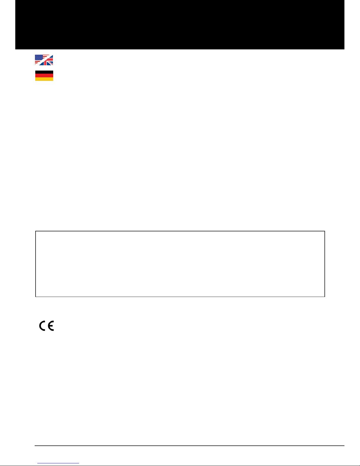
Please put careful the cables and the tonearm through the armboard, pay attention that no wire will
be damaged! Now x the tonearm with the 2 screws on the right and the left side, not to much, so
that you can adjust it in the next steps!
Pic. 4: Putting the tonearm through the armboard
Pic. 3: Mount tonearm base
To mount the tonearm base on your armboard, please use the delivered allen screws (M4 x 10), as
you can see in Pic.1 No. 5.
Page 7
User manual / Bedienungsanleitung
Made in Germany 7
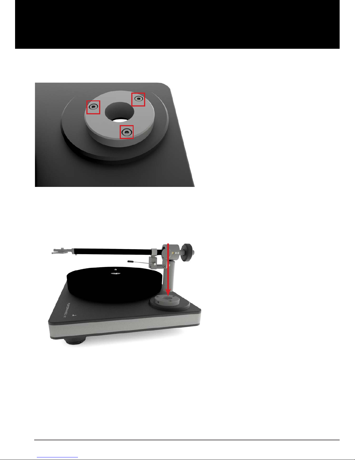
Insure that the distance from the spindle to the pivot point of the tonearm is exactly 222 mm.
Moving the armboard in one direction or another will allow you to locate the correct position.
Once located, tighten the armboard down. Shown in the picture below. Y ou can also use the optional
Clearaudio
cartridge alignment gauge
(Art. No.: AC005/IEC www.analogshop.de ).
For the exact adjustments should be the cartridge mounted!
Pic. 5: Distance from pivot to stylus
222 mm
VTA adjustments are accomplished by loosening the lock screw on the side of the armboard base
(shown in picture 5). Once loose, you can move the arm up or down to achieve the desired VTA.
Tighten the screw when nished. Re-check tracking force after adjusting VTA.
Please adjust the tonearm tube parallel to the turntable chassis!
Pic. 6: VTA-adjustment
Page 8
User manual / Bedienungsanleitung
8 © clearaudio electronic GmbH, 2018/10
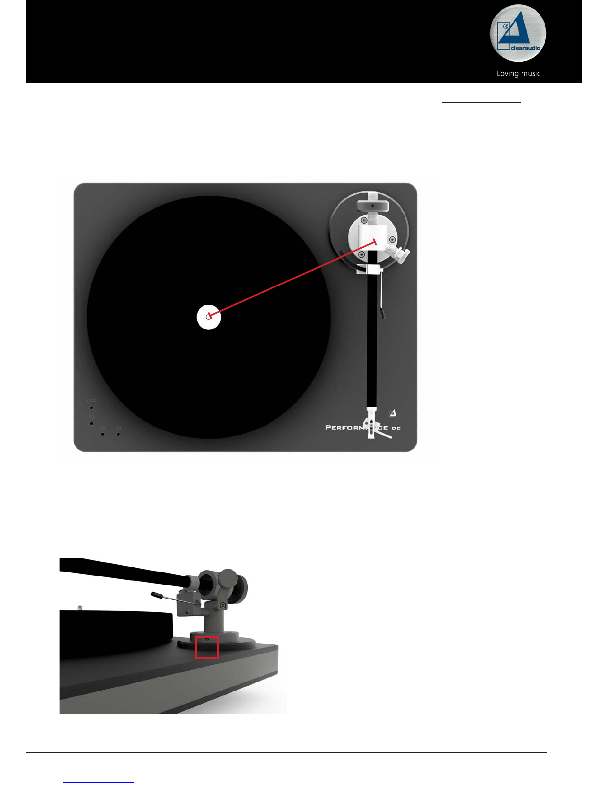
Azimuth adjustments are facilitated through the small (1.5 mm) hex wrench (red marked screw)
on the bottom side of the armwand where the headshell enters the arm tube. Once you loosen this
screw, you´ll be able to rotate the headshell a small amount in either direction. Be sure to tighten
the screw when done.
Pic. 7: Azimuth adjustment
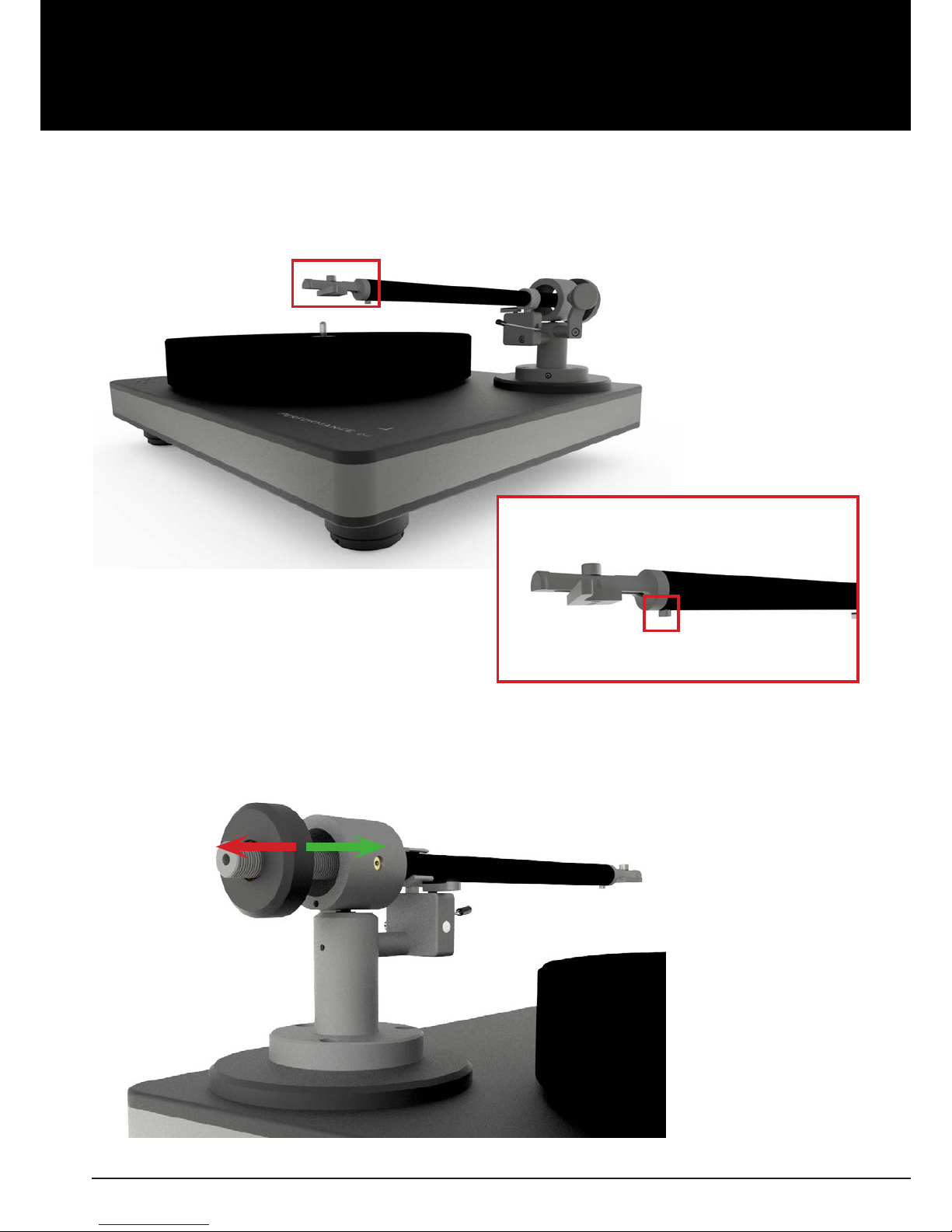
Wind the counterweight on the tonearm tube. Y ou can adjust the tracking f orce of your cartridge by
turning the counterweight (shown in the picture below)
(green arrow = more tracking force / red arrow = less tracking force).
Pic. 8: Screw to adjust the headshell
Pic. 9: Tracking force adjustment
Page 9

User manual / Bedienungsanleitung
Made in Germany 9
Now you are ready for the antiskating adjustment.
This also depends on the tracking force of the cartridge and the diamond shape.
alignment of the antiskating tracking force position of the antiskating screw
minimal antiskating >> 10 – 15mN >> see illustration 1
medium antiskating >> 15 – 20mN >> see illustration 2
maximum antiskating >> 20mN and more >> see illustration 3
Illustration 1 Illustration 2 Illustration 3
(minimal antiskating ) (medium antiskating) (maximum antiskating)
Pic. 10: Alignment of the antiskating
The general setup is now nished.
Connect your
Satisfy Kardan
tonearm now with the phono input of your phono-preamplier.
(More information on adequate phono-preampliers and interconnects you can nd on our website
www.clearaudio.de).
Now you are nally ready to play your vinyl records.
Clearaudio wish you a lot of pleasure with your new
Satisfy Kardan
tonearm.
Page 10

User manual / Bedienungsanleitung
10 © clearaudio electronic GmbH, 2018/10
3. Special notes
3.1 Maintenance
If you don`t use your
Satisfy Kardan
tonearm for a longer time, please move the tonearm lifter in
regular intervals. This avoid that the tonearm hang in a position when you listen to the music again.
3.2 Transportation
Should further transportation of the
Satisfy Kardan
tonearm be necessary, please alway use the
original packing material. Otherwise serious damage could occur.
3.3 Service
If any servicing or repair of a Clearaudio product is necessary, please rst contact your dealer or
distributor. Alternatively contact Clearaudio directly and we will advise y ou of your nearest service
location.
PLEASE RETAIN ALL ORIGINAL PACKAGING. You will need it if this product has to be transported
and/or shipped. Any further questions you may have about this product should be directed to your
local dealer or direct to Clearaudio at:
Clearaudio electronic GmbH
Spardorfer Str. 150
91054 Erlangen
Germany
Phone: +49 9131 40300 100
Fax: +49 9131 40300 119
www.clearaudio.de
www.analogshop.de
info@clearaudio.de
Page 11

User manual / Bedienungsanleitung
Made in Germany 11
4. Technical data
Tonearm version Aluminum silver
Aluminum black
Carbon
Tonearm weight: 350 g 345 g
Cartridge balance range: 2.5 g - 17 g 2.5 g - 17 g
Null points: Inner: 66.0 mm
Outer: 120.9 mm
Inner: 66.0 mm
Outer: 120.9 mm
Audio lead: Clearaudio Direct Wire Plus
(1.1 m) terminated with RCA
connector
Cable-capacity: 156pF/m
Cable-induction: 0,52µH/m
Cable-resistance: 0,46Ω/m
Clearaudio Direct Wire Plus
(1.1 m) terminated with RCA
connector
Cable-capacity: 156pF/m
Cable-induction: 0,52µH/m
Cable-resistance: 0,46Ω/m
Overhang: 17.31 mm 17.31 mm
Overall length: 302 mm 302 mm
Eective tonearm length: 9 inches
(exact 239.31 mm)
9 inches
(exact 239.31 mm)
Distance from pivot: 222 mm 222 mm
Tilt angle:
Maximum of tilt angle
according to the radius:
middle skatingfactor at
a radius of 62.9 mm and
126.9 mm:
25.54 °
0.123°/cm
0.43
25.54°
0.123°/cm
0.43
Warranty: 2 years* 2 years*
* Provided that the warranty card is correctly completed and returned to Clearaudio within 14 days of purchase.
Clearaudio electronic is not responsible for typographical errors in descriptions.
Technical specications subject to change or improvement without prior notice.
Product availability is as long as stock lasts.
Copies and reprints of this documents, including extracts, require written consent from
Clearaudio electronic GmbH; Germany
Page 12

User manual / Bedienungsanleitung
12 © clearaudio electronic GmbH, 2018/10
Sehr geehrte clearaudio Kundin, sehr geehrter clearaudio Kunde,
Sie haben sich für einen
Satisfy Kardan
Tonarm entschieden, ein hochwertiges Produkt der
clearaudio electronic GmbH.
Wir bedanken uns bei Ihnen für das uns entgegengebrachte Vertrauen.
Der Tonarm ist mit einem Tonarmrohr aus Carbon, silbernem oder schwarzen Aluminium erhältlich.
Um alle Vorteile des
Satisfy Kardan
Tonarms nutzen zu können, lesen Sie bitte diese Bedienungsanleitung
aufmerksam durch.
Alle Hinweise dienen dem Ausschöpfen der vollen Klangeigenschaften und bewahren Sie vor
Fehlbedienungen.
Wir wünschen Ihnen viel Freude mit Ihrem neuen clearaudio
Satisfy Kardan
Tonarm.
clearaudio electronic GmbH
Warnung
Das Gerät nicht Regen oder Feuchtigkeit aussetzen.
Das Netzkabel nicht mit feuchten oder nassen Händen anfassen.
Es dürfen keine Gegenstände mit oener Flamme, wie etwa brennende Kerzen, auf dem Gerät
aufgestellt werden.
Zur ausschließlichen Verwendung auf Plattenspielern.
CE-MARKIERUNG
Page 13

User manual / Bedienungsanleitung
Made in Germany 13
Inhaltsverzeichnis
1. Verpackungsübersicht ..................................... 13
2. Montage des Satisfy Kardan Tonarms ............. 14 - 17
3. Besondere Hinweise ........................................ 18
4. Technische Daten ............................................ 19
Garantieinformationen ........................................ 20
Page 14

User manual / Bedienungsanleitung
14 © clearaudio electronic GmbH, 2018/10
1. Verpackungsübersicht
Der clearaudio
Satisfy Kardan
Tonarm wird in einer speziellen Verpackung geliefert, somit wird
ein sicherer Transport gewährleistet. Bitte prüfen Sie den Inhalt der Verpackung anhand des unten
abgebildeten Bildes und der Inhaltsangabe auf Vollständigkeit. Bewahren Sie die Verpackung für
Transportzwecke unbedingt auf.
1.
Satisfy Kardan
Tonarm 5. Schrauben:
- 3x Zylinderkopfschraube (mit Innensechskant) M4 x 10
- 1x Gewindestift M6 x 8 (Edelstahl)
2. clearaudio Tonarmbasis 6. Tonarmeinstellschablone (ohne Abbildung)
3.
Satisfy Kardan
Gegengewicht 7. Bedienungsanleitung, Qualitäts- und
Garantiekarte, Rücklieferschein
(ohne Abbildung)
4. Innensechskantschlüssel:
- 3 mm
- 2,5 mm
- 1,5 mm
Schraubendreher
8.
Abb. 1: Verpackungsübersicht
1
2
3
4
5
Page 15

User manual / Bedienungsanleitung
Made in Germany 15
2. Montage des
Satisfy Kardan
Tonarms
Montage der Aluminium-Klemmbasis auf einem Laufwerk anderer Hersteller:
Um die Aluminium-Klemmbasis auf dem Laufwerkchassis anbringen zu können, müssen erst
die Bohrungen zur Befestigung angebracht werden. Die Maße zum Anzeichnen der exakten
Bohrlochabstände entnehmen Sie bitte der unten abgebildeten Bohrschablone (siehe Abb. 2 ).
Bitte beachten Sie, dass diese Abbildung nicht maßstabsgetreu ist.
Verwenden sie für die Bohrungen einen 3,3 mm HSS-Spiralbohrer. Anschließend schneiden Sie in die
Bohrungen mit einem Gewindebohrer jeweils M4-Gewinde.
Ist das Material das Laufwerkchassis nicht dazu geeignet, es mit Gewinden zu versehen, verwenden
Sie bitte einen 4,5 mm HSS-Spiralbohrer, um die Bohrungen durch das Material zu bohren. In diesem
Fall können Sie den Klemmring mit handelsüblichen Schrauben in der entsprechenden Länge und
den dazu passenden Muttern befestigen (V2A-Inbus).
Abb. 2: Montage der Klemmbasis auf einem Laufwerk anderer Hersteller
Page 16

User manual / Bedienungsanleitung
16 © clearaudio electronic GmbH, 2018/10
Nun führen Sie vorsichtig die Kabel durch die Tonarmbasis, achten Sie bitte darauf, dass keine Kabel
beschädigt oder geknickt werden! Schrauben sie den Tonarm leicht fest, damit Sie Ihn zur genauen
Justage noch bewegen können!
Abb. 3: clearaudio Rundbasis
Abb. 4: Befestigung des Tonarms an der Rundbasis
Bei der Montage der
Satisfy Kardan
Tonarmbasis auf einer clearaudio Rund-Basis, benutzen Sie
bitte die Zylinderkopfschr auben (M4x10). F alls Sie den T onarm auf einem Tonarmausleger oder einer
Tonarmbasis auf einem Fremdlaufwerk montieren wollen, benutzen Sie bitte die vom Hersteller der
Tonarmbasis empfohlenen Schrauben.
Page 17

User manual / Bedienungsanleitung
Made in Germany 17
Zur exakten Einstellung des Drehpunktes des Tonarms empfehlen wir die clearaudio Drehtonarm
Einstellschablone (Art. AC005 unter www.analogshop.de ). Sie können allerdings hierzu auch ein
Lineal benutzen! Hierbei müssen Sie darauf achten, dass der Abstand der Spindel zum Drehpunkt
des Tonarms exakt 222 mm betragen muss! Den Abstand können Sie durch Drehen der Tonarmbasis
einstellen.
Zur Exakten Einstellung des Tonarms, müssen Sie Ihren Tonabnehmer montieren!
Folgen Sie hierbei bitte den Angaben des jeweiligen Herstellers!
Abb. 5: Abstand der Spindel zum Drehpunkt des Tonarms
222 mm
Um die Höhe Ihres Tonarms richtig einzustellen, lösen Sie bitte die Justierschrauben am Fuß der
Tonarmbasis, diese bendet sich seitlich in einer Vertiefung (Bild 5) und kann mit dem Schraubendreher
gelöst und nach der Höheneinstellung wieder angezogen werden! Bitte achten Sie darauf, dass das
Tonarmrohr paralell zum Chassis läuft!!
Abb. 6: Einstellen der Tonarmhöhe
Page 18

User manual / Bedienungsanleitung
18 © clearaudio electronic GmbH, 2018/10
Bitte beachten Sie, dass der Azimuth bereits ab Werk genau eingestellt wurde. Falls der Azimuth
dennoch verändert werden muss, um Geometriefehler eines Tonabnehmers zu kompensieren,
verfahren Sie bitte wie folgt: Lösen Sie die Schraube auf der Unterseite des Tonarmrohrs, nahe des
Headshells. Jetzt können Sie den Azimuth durch Drehen des Headshells im Tonarmrohr verstellen.
Abb. 7: Veränderung des Azimuth
Drehen Sie das Gegengewicht auf das Tonarmrohr. Stellen Sie das Auagegewicht des Tonabnehmers
durch Verdrehen des Gegengewichtes nach vorne oder hinten ein
(grüner Pfeil = mehr Auagekraft / roter Pfeil = weniger Auagekraft).
Abb. 8: Lösen der Schraube auf der Unterseite des
Tonarmrohrs
Abb. 9: Einstellen des Auagegewichts
Page 19

User manual / Bedienungsanleitung
Made in Germany 19
Jetzt können Sie die Antiskatingeinstellung vornehmen. Diese wird in Abhängigkeit der
Tonabnehmerauagekraft getroen:
Einstellung des Antiskating: Auagekraft Position der Antiskatingschraube
Minimales Antiskating >> 10-15mN >> siehe Abbildung 1
Mittleres Antiskating >> 15-20mN >> siehe Abbildung 2
Maximales Antiskating >> 20mN und größer >> siehe Abbildung 3
Abbildung 1 Abbildung 2 Abbildung 3
(minimales Antiskating) (mittleres Antiskating) (Maximales Antiskating)
Abb. 10: Antiskating-Einstellung
Die Tonarmjustage ist nun abgeschlossen.
Nun können Sie den Satisfy Kardan Tonarm mit Ihrem Phonovorverstärker verbinden.
(Mehr Informationen über adäquate Phonovorverstärker nden Sie auf unserer Webseite
www.clearaudio.de).
Der
Satisfy Kardan
Tonarm ist nun spielbereit.
Clearaudio wünscht Ihnen viel Freude beim Musikhören!
Page 20

User manual / Bedienungsanleitung
20 © clearaudio electronic GmbH, 2018/10
3. Besondere Hinweise
3.1 Wartung
Falls Sie Ihren clearaudio
Satisfy Kardan
Tonarm längere Zeit nicht benutzen, empfehlen wir Ihnen
den Tonarmlift in regelmäßigen Abständen zu bewegen, um das Lagerfett geschmeidig zu halten
und ein mögliches Haken des Tonarms beim Abspielen zu vermeiden.
3.2 Transport
Sollte ein weiterer Transport des
Satisfy Kardan
erforderlich sein, verwenden Sie immer nur die
Originalverpackung. Andernfalls könnte Ihr Tonarm ernsthafte Schäden davon tragen.
3.3 Pege
Wenn eine Wartung oder Reparatur an einem clearaudio Produkt erforderlich ist, wenden Sie sich
bitte zuerst immer an Ihren Händler oder Vertriebspartner. Alternativ können Sie clearaudio direkt
kontaktieren und wir werden Sie von Ihrer nächstgelegenen Servicestelle beraten.
Bewahren Sie die vollständige Originalverpackung auf. Sie benötigen diese, wenn das Produkt
transportiert und / oder verschickt werden soll. Alle weiteren Fragen zu diesem Produkt können Sie
an ihren örtlichen Fachhändler oder direkt an clearaudio richten:
clearaudio electronic GmbH
Spardorfer Str. 150
91054 Erlangen
Germany
Tel: +49 9131 40300 100
Fax: +49 9131 40300 119
www.clearaudio.de
www.analogshop.de
info@clearaudio.de
Page 21

User manual / Bedienungsanleitung
Made in Germany 21
4. Technische Daten
Tonarm Version Aluminium silber
Aluminium schwarz
Carbon
Tonarmgewicht: 350 g 345 g
Justierbare Tonabnehmer: 2,5 g - 17 g 2,5 g - 17 g
Nullpunkte: Innerer: 66,0 mm
Äußerer: 120,9 mm
Innerer: 66,0 mm
Äußerer: 120,9 mm
Signalkabel: Clearaudio Direct Wire Plus
(1,1 m) konfektioniert mit
MPC Cinch
Kabel-Kapazität: 156pF/m
Kabel-Induktion: 0,52µH/m
Kabel-Widerstand: 0,46Ω/m
Clearaudio Direct Wire Plus
(1,1 m) konfektioniert mit
MPC Cinch
Kabel-Kapazität: 156pF/m
Kabel-Induktion: 0,52µH/m
Kabel-Widerstand: 0,46Ω/m
Überhang: 17,31 mm 17,31 mm
Gesamtlänge: 302 mm 302 mm
Eektive Tonarmlänge: 9 Zoll /239,31 mm 9 Zoll / 239,31 mm
Achsabstand:
(Dorn bis
Tonarmdrehpunkt)
222 mm 222 mm
Kröpfungswinkel:
Abs. Maximum des
relativen Fehlwinkels (bes.
auf Radius):
Mittlerer Skatingfaktor bei
Radien 62,9 mm und
126,9 mm
25,54 °
0,123°/cm
0,43
25,54°
0,123°/cm
0,43
Garantie: 2 Jahre* 2 Jahre*
* Nur bei korrekt ausgefüllter und eingesandter Garantiekarte an clearaudio innerhalb von 14 Tagen.
Änderungen bleiben vorbehalten. Lieferbar solange Vorrat reicht. Für Druckfehler keine Haftung.
Irrtümer vorbehalten- Kopien und Abdrucke – auch nur auszugsweise – bedürfen der schriftlichen
Genehmigung durch die clearaudio electronic GmbH.
Page 22

User manual / Bedienungsanleitung
22 © clearaudio electronic GmbH, 2018/10
To achieve the full Clearaudio warranty, it is necessary that you ll out and send the corresponding part of
the warranty registration certicate /card back to Clearaudio, within two weeks after purchase.
Only if the product is returned in its original packing Clearaudio can provide the warranty of 2 years.
Um die volle Clearaudio Garantie von 2 Jahren zu erhalten, senden sie uns bitte die beigefügte Garantie/
Registrierkarte vollständig ausgefüllt und innerhalb von 2 Wochen zurück. Bei Rücksendung der Ware ist bitte
darauf zu achten die Originalverpackung zu verwenden.
ENGLISH
WARRANTY
For warranty information, contact your local Clearaudio distributor.
RETAIN YOUR PURCHASE RECEIPT
Your purchase r eceipt is y our permanent r ecor d of a valuable purchase. It should be kept in a safe place to be referred
to as necessary for insurance purposes or when corresponding with Clearaudio.
IMPORTANT
When seeking warranty service, it is the responsibility of the consumer to establish proof and date of purchase.
Your purchase receipt or invoice is adequate for such proof.
FOR U.K. ONLY
This undertaking is in addition to a consumer‘s statutory rights and does not aect those rights in any way.
FRANÇAIS
GARANTIE
Pour des informations sur la garantie, contacter le distributeur local Clearaudio.
CONSERVER L‘ATTESTATION D‘ACHAT
L‘attestation d‘achat est la preuve permanente d‘un achat de valeur. La conserver en lieu sur pour s‘y reporter aux ns
d‘obtention d‘une couverture d‘assurance ou dansle cadre de correspondances avec Clearaudio.
IMPORTANT
Pour l‘obtention d‘un service couvert par la garantie, il incombe au client d‘établir la preuve de l‘achat et d‘en corr oborer
la date. Le reçu ou la facture constituent des preuves susantes.
DEUTSCH
GARANTIE
Bei Garantiefragen wenden Sie sich bitte zunächst an Ihren Clearaudio Händler. Heben Sie Ihren Kaufbeleg gut auf.
WICHTIG!
Die Angaben auf Ihrer Quittung erlauben uns die Identizierung Ihres Gerätes und belegen mit dem Kaufdatum die
Dauer Ihrer Garantie-Ansprüche. Für Serviceleistungen benötigen wir stets die Gerätenummer. Diese nden Sie auf dem
Typenschild auf der Rückseite des Gerätes oder auch in der beigefügten Garantie-Registrierkarte.
NEDERLANDS
GARANTIE
Voor inlichtingen omtrent garantie dient u zich tot uw plaatselijke Clearaudio.
UW KWITANTIE, KASSABON E.D. BEWAREN
Uw kwitantie, kassabon e.d. vormen uw bewijs van aankoop van een waardevol artikel en dienen op een veilige plaats
bewaard te worden voor evt, verwijzing bijv, in verbend met verzekering of bij correspondentie met Clearaudio.
BELANGRIJK
Bij een evt, beroep op de garantie is het de verantwoordelijkheid v an de consument een gedateerd bewijs v an aankoop
te tonen. Uw kassabon of factuurzijn voldoende bewijs.
Page 23

User manual / Bedienungsanleitung
Made in Germany 23
ITALIANO
GARANZIA
L’apparecchio è coperto da una garanzia di buon funzionamento della durata di un anno, o del periodo previsto dalla
legge, a partire dalla data di acquisto comprovata da un documento attestante il nominativo del Rivenditore e la data di
vendita. La garanzia sarà prestata con la sostituzione o la riparazione gratuita delle parti difettose.Non sono coperti da
garanzia difetti derivanti da uso improprio, errata installazione, manutenzione eettuata da personale non autorizzato
o, comunque, da circostanze che non possano riferirsi a difetti di funzionamento dell’apparecchio. Sono inoltre esclusi
dalla garanzia gli interventi inerenti l’installazione e l’allacciamento agli impianti di alimentazione.
Gli apparecchi verranno riparati presso i nostri Centri di Assistenza Autorizzati. Le spese ed i rischi di trasporto sono a
carico del cliente. La casa costruttrice declina ogni responsabilità per danni diretti o indiretti provocati dalla inosservanza
delle prescrizio-ni di installazione, uso e manutenzione dettagliate nel presente manuale o per guasti dovuti ad uso
continuato a ni professionali.
ESPAÑOL
GARANTIA
Para obtener información acerca de la garantia póngase en contacto con su distribuidor Clearaudio.
GUARDE SU RECIBO DE COMPRA
Su recibo de compra es su prueba permanente de haber adquirido un aparato de valor, Este recibo deberá guardarlo
en un lugar seguro y utilizarlo como referencia cuando tenga que hacer uso del seguro o se ponga en contacto con
Clearaudio.
IMPORTANTE
Cuando solicite el servicio otorgado por la garantia el usuario tiene la responsabilidad de demonstrar cuándo efectuó la
compra. En este caso, su recibo de compra será la prueba apropiada.
Page 24

User manual / Bedienungsanleitung
24 © clearaudio electronic GmbH, 2018/10
Page 25

User manual / Bedienungsanleitung
Made in Germany 25
Page 26

clearaudio electronic GmbH
Spardorfer Straße 150
91054 Erlangen
Germany
Phone/Tel.: +49 9131 40300 100
Fax: +49 9131 40300 119
www.clearaudio.de
www.analogshop.de
info@clearaudio.de
Handmade in Germany
(Technische Änderungen vorbehalten - Technical specication are subject to change
without prior notication) 2018
© clearaudio electronic GmbH, 2018/10 Made in Germany
 Loading...