

Page 1
1
1
0
0
0
0
0
0
S
S
e
e
r
r
iie
e
s
s
U
U
s
s
e
e
r
r
M
M
a
a
n
n
u
u
a
a
l
l
4
4
C
C
h
h
a
a
n
n
n
n
e
e
llD
D
V
V
R
R
Page 2

1. IMPORTANT SAFETY INSTRUCTIONS
2. BEFORE INSTALLATION
3. MAIN FEATURES
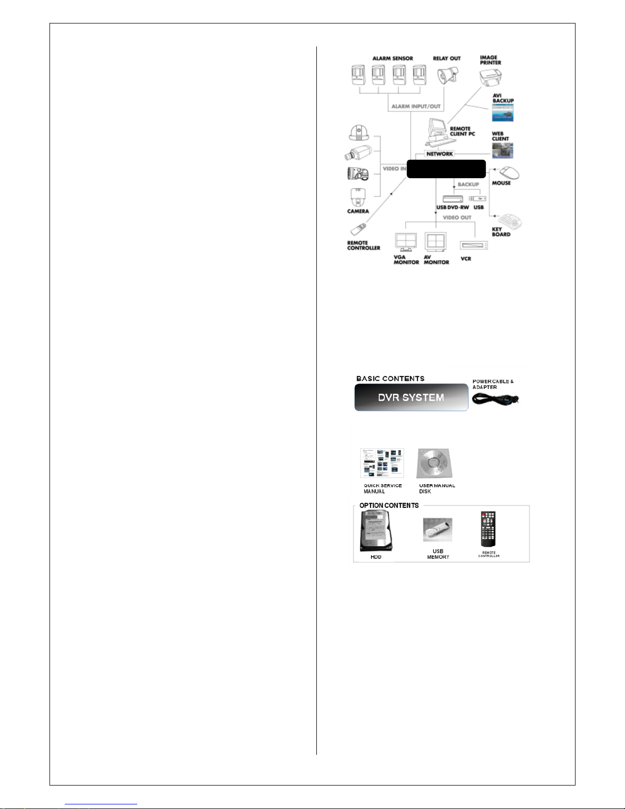
4. SYSTEM ORGANIZATION
5. SYSTEM CONTENTS
6. SYSTEM SURFACE OVERVIEW
6.1. FRONT
6.2. REAR
6.2.1 Video Input
6.2.2 Monitor Out
6.2.3 Audio In/ Out
6.2.4VIDEO
Out
put
6.2.5Alarm in/ Relay/ RS
-
485
6.2.6NETWORK
6.2.7DC-12V
6.3. REMOTE CONTROLLER
7. RUNNING SYSTEM
7.1. DIVISION SCREEN MODE
7.2. SEQUENCE MODE
7.3.
REC START(
PANICRECORDING
)
7.4. PTZ7.5
. LOG OFF
8. SYSTEM SETUP
8.1.
DISPLAY
8.1.1. OSD
8.1.2. MONITOR
8.2. DISPLAY
8.2.1 CAMERA TITLE
8.2.2 COLOR SETUP
8.2.3 PTZ SETUP
8.2.4 MOTION SENSOR
8.2.5CAMERA MODE
8.3 SOUND
8.3.1 AUDIO
8.3.2 BUZZ
ER
8.4SYSTEM
8.4.1. DATA/TIME
8.4.2. NETWORK
8.4.3. MAIL
8.4.4 USER MANAGEMENT
8.4.5 SYSTEM MANAGEMENT
8.4.6 CONTROL DEVICE
8.5 EVENT /SENSOR
8.5.1 HDD EVENT
8.5.2 ALARM INPUT
8.5.3 ALARM OUT
8.5.4 BUZZER OUT
8.5.5. E
-
MAIL NOTIFICATION.
9. RECORD SETUP
9.1 SIMPLE RECORDING
9.2 ADVANCE RECORDING
9.3 MANUAL RECORDING
10. SEARCH
10. 1. SEARCH BY TIME
10. 2. SEARCH BY EVENT
11. ARCHIVE
12. WEB CONNECTIONS.
13. SMART PHONE CONNECITONS.
1. IMPORTANT
SAFETY
INSTRUCTIONS
Page 3

1) Read these instructions.
2) Keep these instructions.
3) Heed all warnings.
4) Follow all instru
ctions.
5) Do not use this apparatus near water.
6) Clean only with a dry cloth.
7) Do not block any of the ventilation openings.
Install in accordance with the Manufacturer's instructions.
8) Do not install near any heat sources such as radiators,
h
eat registers, stoves,
or other apparatus that produce
heat.
9) Do not defeat the safety purpose of the polarized or
grounding type plug. A polarized plug has two blades with
one wider than the other.Agrounding type plug has two
blades and a third groun
ding prong.
The wide blade or the third prong is provided for your
safety.
When the provided plug does not fit into your outlet,
consult an electrician for replacement of the obsolete
outlet.
.10)
Protect the pow
er cord from being walked on or
pinched
particularly at plugs, convenience receptacles, and the point
where they exit from the app
aratus.
11)Only use the attachments/accessories specified by the
manufacturer.
12) Use only with a cart, stand, tripod, bracket, or table
specified by the manufa
cturer,or sold with the apparatus.
When a cart is used, use caution when moving the
cart/apparatus combination to avoid injury from tip
-
over.
13) Unplug this apparatus during lightning storms or when
unused for long periods of time.
14) Refer al
l servicing to qualified service personnel.
Servicing is required when the apparatus has been damaged
in any way, such as power supply cord or plug is damaged,
liquid has been spilled or objects have fallen into the
apparatus, the apparatus has been expos
ed to rain or
moisture, does not operate normally, or has been dropped.
15) This equipment is indoor use and all the communication
wirings are limited to inside of the building.
16) The socket
-
outlet shall be installed near the equipment
and shall be e
asily accessible.
17) CAUTION
RISK OF EXPLOSION IF BATTERY IS REPLACED BY
AN INCORRECT TYPE.
DISPOSE OF USED BATTERIES ACCORDING TO THE
INSTRUCTIONS
.
# Operation Max temperature : 40
℃
# USB Load condition: USB
Ports (5
VDC
, Max. 500 mA)
2. BEFORE INSTALLATION
● Installation should be carried out only by qualified
personnel and in accordance with any electrical regulations
in force at the time.
● The DVR must be placed on a stable
surface or mounted
in an approved cabinet.
Adequate ventilation must be provided, taking particular
care not to block any of the air vents on the DVR.
● Adequate protection against lightning strikes and power
surges must be installed to prevent damage to
the DVR.
● Any safety warnings on the DVR and
in these
instructions must be adhered to.
● If cleaning is necessary, shutdown the DVR and
disconnect power first. Use a soft dry cloth only never use
any abrasive cleaners.
● Do not attempt to service or r
epair the DVR as opening
or removing covers may expose dangerous voltages or
other hazards. Refer all servicing to qualified service
personnel.
3. MAIN FEATURES
MOUSE
CONTROL
Designed to be
controll
ed by mouse and easy to use.
ENHANCED GRAPHICAL USER
INTERFACE [GUI]
The DVR menu structure and on screen display is
presented in a simple to use and logical GUI format.
GENUINE TRIPLEX OPERATION
The DVR will continue to record at full frame rate during
local playback, local setup, multi user remote viewi
ng and
playback and remote setup.
BACKUP
Recorded footage (including audio) can be archived to
USB memory stick or CD.
Playback software is embedded with the backup files and
the backup also contains the system event log and backup
log for full traceabil
ity.
COMPREHENSIVE RECORDING SETUP
Recording can be scheduled, alarm activated
(Option)ormotion activated. For each type of recording, frame rates,
image quality and audio recording properties can be
adjusted per hour, per day and for each individual ch
annel.
The DVR also has a panic recording feature from the front
panel
which overrides all other recording settings to
provide the best quality recording in the event of an
emergency.
TELEMETRYCONTROL
Full telemetry control is available from the front
panel or
remote connection and a wide number of speed dome
protocols are supported. Protocols can be set individually
Page 4
for each channel and telemetry speed can be adjusted to
suit particular speed domes.
LIVE DISPLAY
The DVR displays single or multi screen
images and also
has several sequence modes.
CONFIGURATION BACKUP
All configuration settings on the DVR can be saved
to USB
memory stick or a PC
remotely.
The saved data can then be uploaded to other DVR units
allowing rapid deployment where more than on
e DVR is
being installed.
EMAIL SUPPORT
The DVR can send emails to specific users to notify events
such as alarm, motion detection, hard drive failure etc.
AUDIO
(Option)
1
audio inputs are supported which can be assigned to any
video channel. Live and r
ecorded audio can be Monitored
remotely over the internet and remote ‘talkback’ audio
transmission to the DVR is also possible.
PTZ CONTROL
(Option)
Full PTZ control is available from the front panel or remote
connection and a wide number of speed Dome pr
otocols
are supported. Protocols can be set individually for each
channel and PTZ speed can be adjusted to suit particular
speed domes.
EXTENSIVE MONITOR SUPPORT
(Option)
The DVR has
2
main monitor outputs (
VGA and
BNC)which can be used simultaneously.
S
upp
ort is also provided for 1
spot monitors and
the
spot
monitor output can be programmed in the DVR setup.
ALARM IN / RELAY OUT
(Option)
The DVR has 4Alarm in and 1 Relay out
4. SYSTEM ORGANIZATION
5. SYSTEM CONTENTS
6. SYSTEM SURFACE OVERVIEW
DVR SYSTEM
Page 5
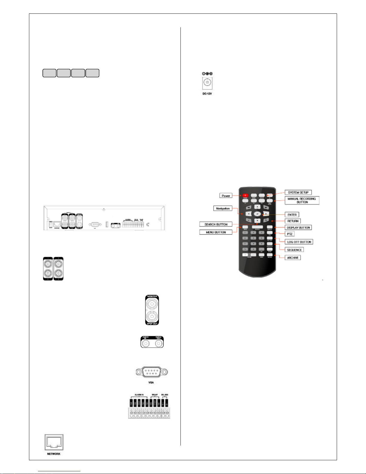
6.1. FRONT
USB PORT
Port for USB devices such as
mouse and
USB
backup
device
.
POWER
Turn on power of system.
DISPLAY
Shift display mode between split and full
screen
mode.
SEARCH
Enter to search menu
MENU
Enter to sys
tem configuration menu.
NAVIGATION KEY
Use
for navigating on menu or control PTZ.
6.2.REAR
(PLUS MODEL)
6.2.1 Video Input
Connect the coaxial cables from the video
sources to the BNC video in Connectors.
6.2.2 Monitor Out
& Spot Out
(
Option
)
Connect AV m
onitor for main
screen and
Spot popup purpose
.
(Option)
6.2.3 Audio In/ Out
(Option)
Connect Mic to Input /
Connect
Speaker
to Output
6.2.4VIDEO OUT
PUT
Provide f
orRGB monitor output
6.2.5Alarm in/ Relay/ RS
-
485
(Option)
Alarm in:
Connect Sensor devices
RELAY: Connect Relay device for
Alarm out.
RS-485: Connect PTZ camera or
Keyboard controller.
6.2.6NETWOR
K
Connect RJ
-
45 for local network or Internet.
6.2.7DC-12V
Connect Power Source from PowerAdapter.
♣
BASIC MOD
EL DOESN
’
T SUPPORT BELOW;
1.SPOT OUT
2.AUTION IN / OUT
3.ALARM IN / RELAY OUT
4.RS-485
6.3. REMOTE CONTROLLER
7. RUNNING SYSTEM
7.1. DIVISION SCREEN MODE
Double click of mouse button for changing mode between
division and full mode
POWER
DISPLAY
SEARCH
MENU
Page 6
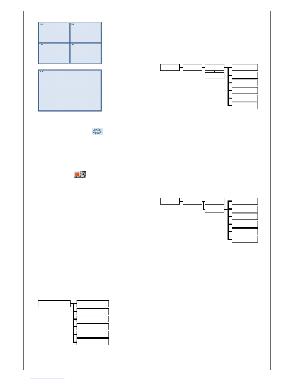
7.2. SEQU
ENCE MODE
Click the right mouse button on the Live Display screen
and Click the
SEQUENCE
menu.
7.3.
REC START (
Panic Recording
)
Panic recording will override all standard recording settings
to provide, by default, continuous recording on all channels.
Press the
REC START
button. The top right of the display
shows a red square with
P
to indicate that the DVR is in
panic recording mode.
Press the
REC STOP
button again to return to normal
re
cording mode.
7.4.
PTZ
(
Option)
Click the right mouse button o
n the Live Display screen
and Click the
PTZ
menu.
Pan, tilt movement, ZOOM, FOCUS, IRIS are controller by
PTZ control box.
(Preset support)
7.5. LOG OFF
Click the right mouse button on the Live Display screen
and Click the
LOG OFF
menu.
*
KEY LOCK: Pro
hibit
pressing
any key from front panel
and
remote controller
.*LOG OFF: Exit from Administrator connection, so prohibit
to access menu from unauthorized user.
8. SYSTEM SETUP
Click the right mouse button on the Live Displa
y screen
and Click the
SETUP
menu.
Press the
SETUP
button to bring up the menu login screen.
Only operators with ADMIN rights can configure the DVR.
Enter the default password of ‘1234’.
8.1. DISPLAY
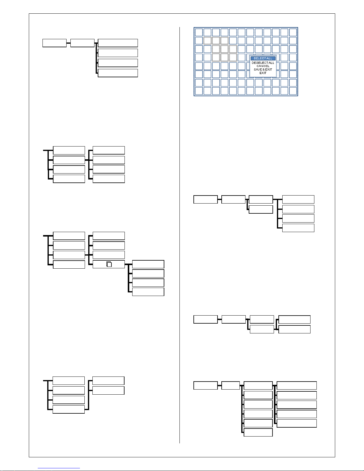
8.1.1. OSD
STATUS BAR
: T
urns the status bar at the bottom of the
live display ON or OFF.
CAMERA TITLE
: Determines whether the camera title is
displayed.
EVENT ICON
: Determines whether the DVR recording
status is shown at the top right of each channel
displ
ay window.
BORDER
: Determines whether there is a border around
each channel in multi screen display mode.
MOTION SENSOR DISPLAY
: If false motion recording is
occurring, the operator can use this feature to
d
etermine and rectify the cause in
real time
.
MOTION COLOR
: The color of the blocks displayed when
MOTION SENSOR DISPLAY
8.1.2. MONITOR
SEQUENCE DWELL
:
The time that each screen is
displayed in a sequence operation.
SPOT OUT D
WEL
: Duration for changing each
screen
on
monitor.
DEINTERLACE MODE
: Display image as 2CIF resolution
for D1 resolution
recording data
.
ALARM POP
-
UP MODE
: When set to ON, an alarm input
will cause the associated channel to display full screen.
ALARM POP
-UPDWELL
: Determines how long the full
screen popup is displayed after an alarm input. If the alarm
condition continues, the popup screen is displayed
constantly.
MOTION POP
-
UP MODE
: When set to ON, motion
detection will cause the associated channel to displ
ay full
screen.
MOTION POP
-
UP DWELL
: Determines how long the full
screen popup is displayed after motion detection. If motion
continues, the popup screen is displayed constantly.
OSD
SEQUENCE DWELL
ALARM POP
-
UP MODE
MOTION POP
-
UP MODE
DEINTERLACE MODE
SPOT OUT DWEL
Monitor
MOTION POP
-
UP DWELL
Display
System Setup
System Setup
Display
System
Event/Sensor
Sound
Camera
Disk Manage
OSD
Status
BarBorder
Motion Sensor
Event Icon
Camera Title
Monitor
Motion Color
Display
System Setup
Page 7
8.2. DISPLAY
8.2.1 CAMERA TITLE
Click the
CAMER
A TITLE
menu and click the ON/OFF
menu on the COVERTmenu.
Click the CAM No on the TITLE menu and change the
camera name.
COVERT
: When set to ON, the camera image is not
displayed in live display but continues to be recorded.
TITLE
: For each camera, a tit
le of up to 11 characters can
be set using the virtual keyboard.
8.2.2 COLOR SETUP
Click the
COLOR SETUP
menu and click the value on the
BRIGHTNESS, CONTRAST, TINT and COLOR menu.
Brightness, contrast, tint and color can be
adjusted for
each individual channel. Highlight which channel to modify
and press
ENTER
.
8.2.3 PTZ SETUP
Click the
PTZ SETUP
menu and click the each value on
the ADDRESS, PROTOCOLand BAUD RATEmenu.
ADDRESS
: The unique ID of
the PTZ device.
PROTOCOL
: The protocol of the PTZ device.
BAUD RATE
: The baud rate of the PTZ device.
8.2.4 MOTION SENSOR
Click the
MOTION SENSOR
menu and click the value on
the SENSITIVITY menu.
SENSITIVITY:
Between 1 (Lowest) and 10 (Highest) and
dete
rmines the degree of motion required before
recording is activated.
AREA
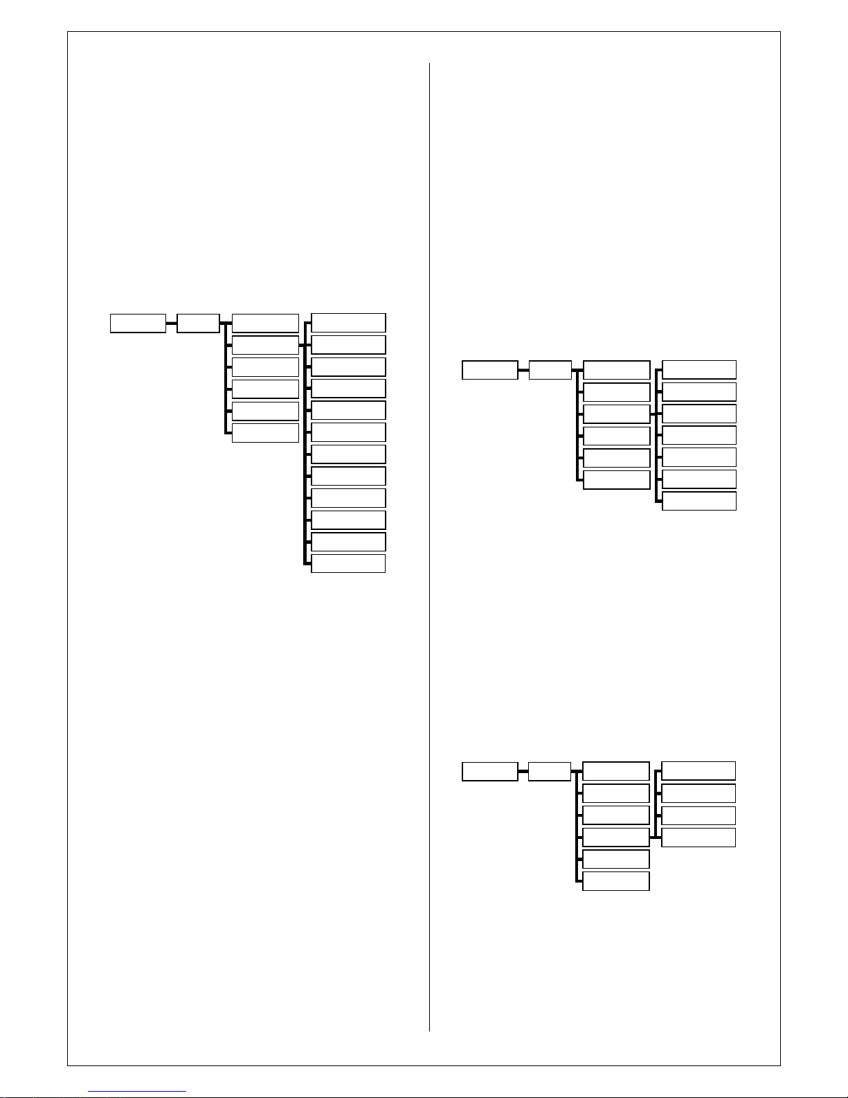
SETUP:
Choosing this option allows the operator to
define which areas of the image are monitored
for
motion detection.
8.2.5CAMERAMODE
LINELOCK CAMERA MODE
When set to ON, the line
-
lock camera is displayed in live
display.
When set to OFF, the scre
en is slightly trembled on line
-
lock camera with AC power supply.
8.3.SOUND
8.3.1 AUDIO
Click the
SOUND
menu.
Click the
AUDIO
menu and click the ON/OFF menu.
LIVE AUDIO
: When set to ON, the selected audio channel
can be monitored on the AUDIO OUTPUT.
AUDIO MONITORING CHANNEL
: Set as CH1
NETWORK AUDIO TX
: When set to ON, live
and playback
audio is transmitted to a remote PC connection.
NETWORK AUDIO RX
: When set to ON, allows a remote
PC connection to send audio back to the DVR.
8.3.2 BUZZER
Click the
BUZZER
menu and click the ON/OFF menu.
KEYPAD
:
When set to ON, each front panel button press is
confirmed by a beep.
IR REMOTE
: When set to ON, each command received
from the IR remote is confirmed by a beep.
8.4. SYSTEM
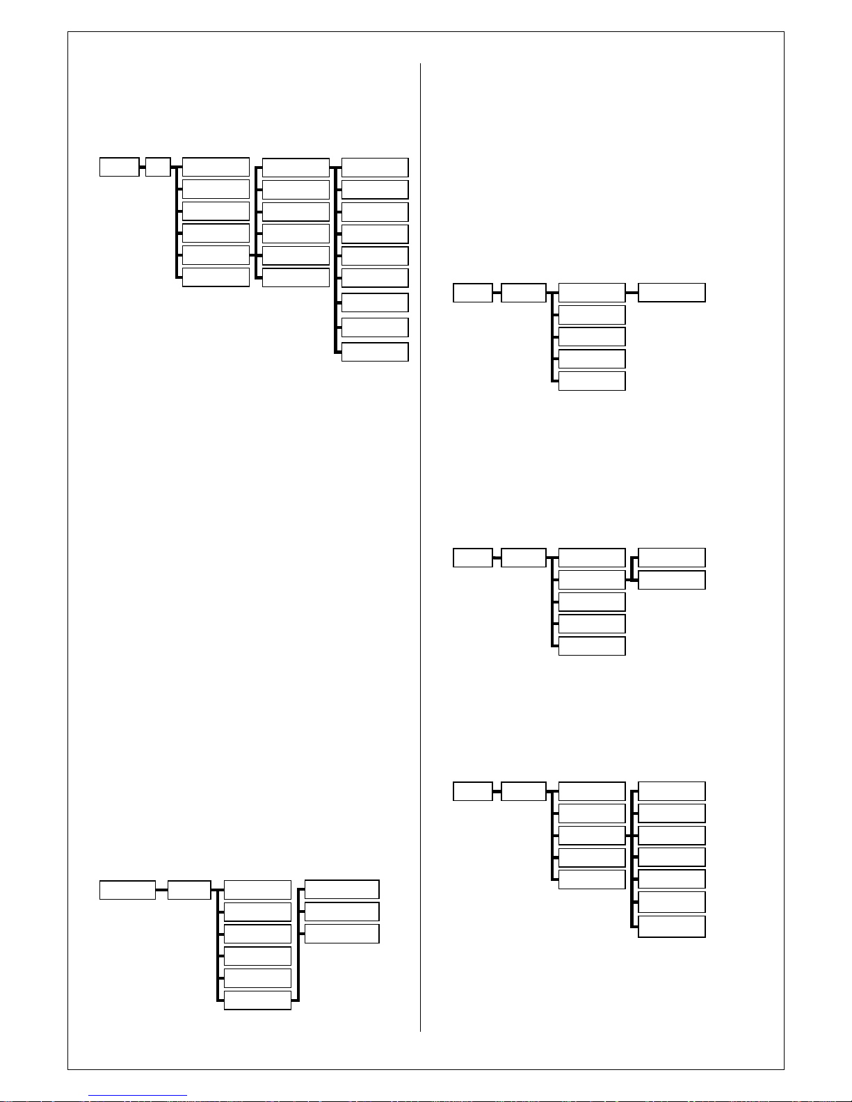
8.4.1. DATA/TIME
Click the
SYSTEM
menu.
DATE/TIME
DATETIME
NETWORK TIME SERVER SETUP
TIME ZONE SETUP
TIME FORMAT
DATE FORMAT
SYSTEM
System Setup
USER MANAGEMENT
SYSTEM MANAGEMENT
MAIL
NETWORK
CONTROL DEVICE
AUDIO
KEYPAD
REMOTE CONTROL
BUZZER
SOUND
System Setup
AUDIO
LIVE AUDIO
NETWORK AUDIO RX
NETWORK AUDIO TX
AUDIO MONITOR CHANNEL
BUZZER
SOUND
Sys
tem Setup
Camera Title
SENSITIVITY
AREA
Color Setup
PTZ Setup
Motion Sensor
Camera Title
ADDRESS
.
BAUDRATE
PROTOCOL
Color Setup
PTZ Setup
Motion Sens
or
CHANNEL NO.
AUTO FOCUS
AUTO IRIS
P/T SPEED
Camera
Title
BRIGHTNESS
COLOR
TINT
CONTRAST
Color Setup
PTZ Setup
Motion Sensor
Camera Title
Color Setup
Camera
System Setup
PTZ Setup
Motion Sensor
Page 8
Click the
DA
TE / TIME
menu and click the ON/OFF menu.
DATE TIME
: Allows the operator to set or modify the
current date & time.
DATE FORMAT
: Determines how the date is displayed.
TIME FORMAT
: Determines how the time is displayed.
NETWORK TIME SERVER SETUP
: If the DVR
is
connected to the Internet, the time and date can be
accurat
ely set by selecting SYNC and
pressing
ENTER
.
TIME ZONE SETUP
: should be set according to the region
that the DVR is used in.
D.S.T.
: When set to ON, the DVR will automatically adjust
the time b
y one hour on the relevant date in
spring and autumn.
8.4.2. NETWORK
Click the
NETWORK
menu and click the ON/OFF menu.
DHCP
: When enabled, the DVR will obtain an IP address
automatically if connect
ed to a DHCP ser
ver
or router.
DDNS
: When enabled, the DVR can be accessed through
a Dynamic DNS server.
Commonly used if a broadband connection does not have
a static IP address.
IP ADDRESS
: If DHCP is not being used, the IP address
can be manually set.
GATE
WAY
: If DHCP is not being used, the gateway IP
address can be manually set.
SUBNET MASK
: If DHCP is not being used, the subnet
mask can be manually set.
1ST DNS SERVER
: If DHCP is not being used, the first
DNS server can be manually set.
2ND DNS SERVER
: I
f DHCP is not being used, the second
DNS server can be manually set.
DDNS SERVER
: If DDNS is enabled, the host DDNS
server is specified here.
You can set DDNS SETUP, when t
he DDNS SERVER
(dvrlink.net) is selected
,
<
DDNS SE
TUP
>
<User ID> and <Password> sho
uld be the same to the
router
user information.
User
can check DDNS STATUS, when the <DDNS
STATUS> button is pressed.
Default
<
DDNS HOST NAME
>
is Mac Address so user can
connect by two different way
s.
(Mac address / Own host
name)
a. 00115ff00213.dvrlink.
netb.1234
.dvrlink.net
,
User can enter any
DDNS Host name
using
Virtual
Keyboard
.
RTSP SERVER
PORT
: The port number that the DVR
uses to support remote connection from the client
software.
WEB SERVER PORT
: The port numb
er that the DVR uses
to support remote connection from Internet
Explorer or other web browsers.
ALIAS
: Display full domain name for accessing DVR.
T
his will be act
ivated when press AUTO button beside of
WEB SERVER PORT.
MAX TX SPEED
: Specifies the maximum bandwidth that
the DVR can use during a remote connection
8.4.3. MAIL
Click the
MAIL
menu and click the ON/OFF menu.
DEFAUT SERVER:
Use default mail server for sending
email notification.
SERVER:
The SMTP outbound email server that should be
used to send email notifications.
PORT:
The outbound email port number.
SECURITY:
Set to OFF if the SERVER does not require a
username and password to connect.
USER:
Enter a username to identify the DVR
in email
messages.
PASSWORD:
If SECURITY is set to ON, enter the
password here.
TEST E
-
MAIL
: Send a test email to registered users.
8.4.4 USER MANAGEMENT
Click the
USER MANAGEMENT
menu and double click
the
ADMIN
on the GROUP
menu.
By default, the DVR is configured with a user ID of ADMIN,
belonging to the ADMIN group and with a password of
1234.
As well as the ability to add new users, existing user details
can be modified.
To modify user details, highlight the user with the g
reen
cursor then double click.
DATE/TIME
USER ID
PASSW
ORD EXPIRY
E-MAIL
GROUP ID
SYSTEM
System Setup
USER MANAGE
MENT
SYSTEM MANAGEMENT
MAIL
NETWORK
CONTROL DEVICE
DATE/TIME
DEAFULTSERVER
SECURITY
USER
PORT
SERVER
SYSTEM
System Setup
USER MANAGEMENT
SYSTEM MANAGEMENT
MAIL
NETWORK
CONTROL DEVICE
PASSWORD
TEST E-MAIL
DATE/TIME
DHCP
IPADDRESS
GATEWAY
WEB SERVICE
DDNS
SYSTEM
System Setup
USER MANAGEMENT
SYSTEM MANAGEMENT
MAIL
NETWORK
CONTROL DEVICE
SUBNET MASK
1STDNS SERVER
2NDDNS SERVER
DDNS SERVER
RTSP SERVER PORT
WEB SERVER PORT
MAX TX SPEED
Page 9
8.4.5 SYSTEM MANAGEMENT
Click the
SYSTEM MANAGEMENT
menu.
And click the PRESS menu for FW Upgrade, Factory
Default and System Data.
Click PRESS button on SYSTEM IN
F
ORMATION part.
IP ADDRESS
: Show
s either the manual IP address
entered in NETWORK setup or the IP address assigned by
a DHCP server if enabled.
MAC ADDRESS
: Shows the MAC (Media Access Control)
address of the DVR. It is unique
–
no other
network device has th
is MAC address.
DISK CAPACITY
: The first value shows the amount of
hard drive capacity used by recorded footage, the
second value shows the total hard drive capacity installed.
F/W version
: Shows the firmware version of the DV
R.
H/W version
: Shows the hardware version of the DVR.
VIDEO SIGNAL TYPE
: The DVR automatically switches
between PALand NTSC depending on the
channel 1 input signal at power on.
SYSTEM NAME
: Asystem name of up to 10 charact
ers
can be defined. It is used so that notification
emails can be identified.
F/W UPGRADE
: Firmware updates may be released
periodically to enhance system performance and
add extra features. The operator
can upgrade the firmware
using a USB memory stick.
FACTORY DEFAULT
: If settings have been changed which
causeserratic behavior, the factory default
settings can be loaded.
SYSTEM DATA
: System settings can be saved to a
USB
memory stick. The settings can be reloaded
in case of accidental factory reset or can be transferred to
another DVR if multiple
units need to be installed with the same settings. All
information
is saved apart from
network settings and system name.
8.4.6 CONTROL DEVICE
Click the
CONTROL DEVICE
menu.
And select the SYSTEM ID, PTZ Protocol and camera
BAUD RATE.
This will allow up to 254 DVRs
to be controlled from the
same keyboard.
SYSTEM ID
: If more than one DVR is connected on the
same RS485 bus, each one must have a unique ID.
Note
: If use more than one DVR on stack, each DVR must
have unique ID for control by Remote controller.
PROTOCOL
: M
ust be set by Control Device.
BAUD RATE
: Must be set to match the baud rate of the
PTZ controller.
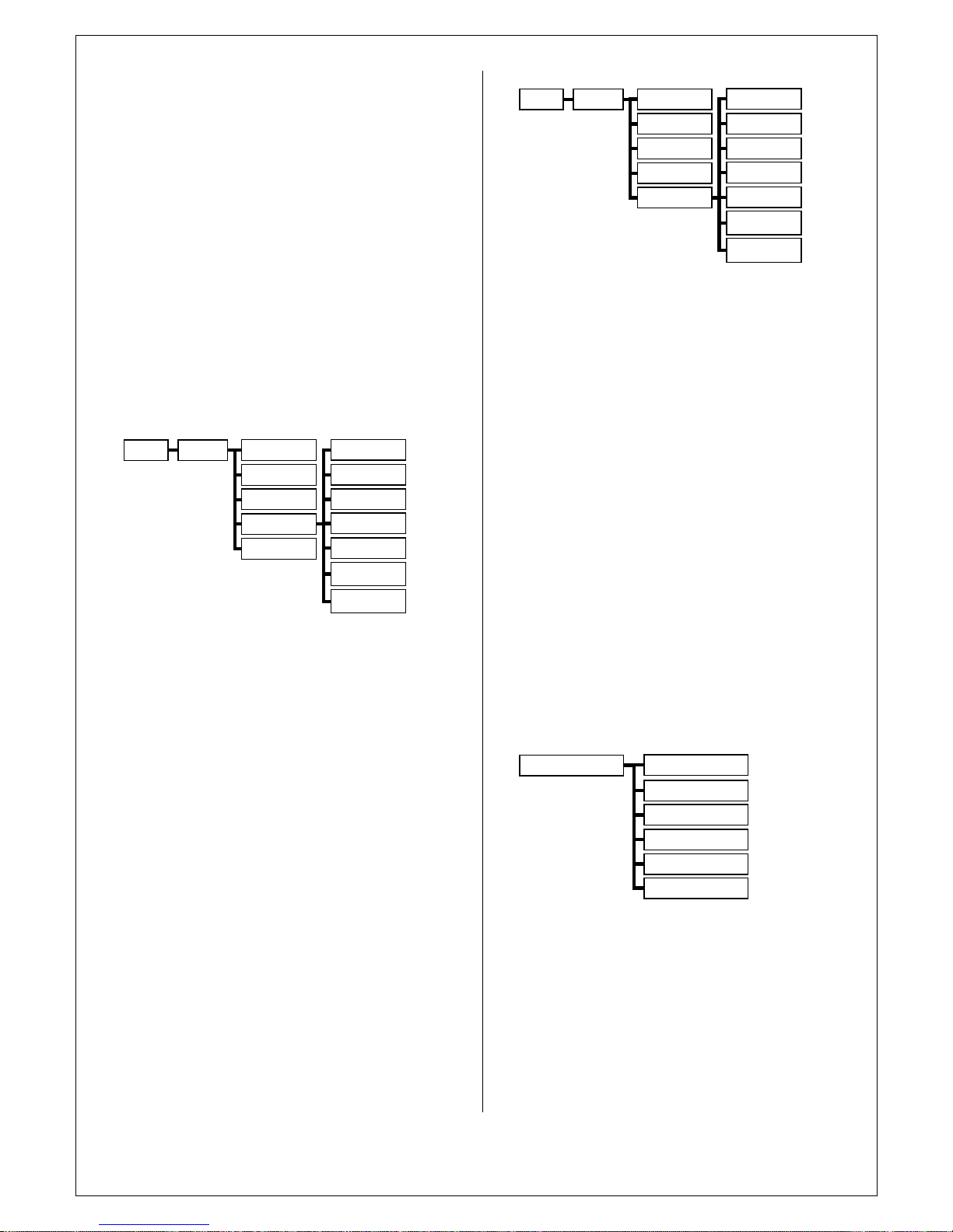
8.5 EVENT /SENSOR
8.5.1 HDD EVENT
Click the
EVENT / SENSOR
menu.
Click the
HDD EVENT
menu a
nd click the DRIVE, SMART
ALARM
.The DVR can monitor the hard drives and detect problems
that may be developing.
DISK FULL EVENT:
Makes alarm when disk full to
recording data
SMART ALARM
: Enables SMART disk monitoring.
8.5.2 ALARM INPUT
Click the
ALARM INPUT
me
nu and click the OPERATION
and TYPE value.
Determines the behavior of each alarm
input
.
OPERATION
:
Alarm inputs can be enabled or disabled.
TYPE
: Alarm inputs can be set as normally open or
normally closed.
8.5.3 ALARM OUT
C
lick the
ALARM OUTPUT
menu and click the each value.
Behavior settings
OPERATION
: The selected alarm output can be enabled or
disabled.
MODE
:
HDD EVENT
OPERATION
DURATION
ALARM
HDD EVENT
MODE
EVENT/SENSOR
System Setup
BUZZER OUTPUT
E-MAIL NOTIFICATION
ALARM OUTPUT
ALARM I
NPUT
VIDEO LOSS
MOTION
HDD EVENT
OPERATION
TYPE
EVENT/SENSOR
System Setup
BUZZER OUTPUT
E-MAIL NOTIFICATION
ALARM OUTPUT
ALARM INPUT
HDD EVENT
DISK FULL EVENT
EVENT/SENSOR
System Setup
BUZZER OUTPUT
E-MAIL NOTIFICATION
ALARM OUTPUT
ALARM INPUT
DATE/TIME
SYSTEM ID
BAUDRATE
PROTOCOL
SYSTEM
System Setup
USER MANAGEMENT
SYSTEM MANAGEMENT
MAIL
NETWORK
CONTROL DEVICE
DATE/TIME
SYSTEM INFORMATION
FACTORYDEAFULT
SYSTEM DATA
F/W UPGRADE
SYSTEM NAME
SYSTEM
System Setup
USER MANAGEMENT
SYSTEM MANAGEME NT
MAIL
NETWORK
CONTROL DEVICE
PASSWORD
IPADDRESS
MAC ADDRESS
DISK CAPACITY
F/W VERSION
H/W VERSION
VIDEO SIGNAL
DDNS SERVER
NET CLIENT PORT
WEB SERVER
Page 10
Can be either
TRANSPARENT
(
the output is active only
when t
he trigger criteria is presen
t)orLATCHED (the
out
put is active for a set period of time after a trigger).
If set to <LATCHED>, the alarm will sound for as much
time as defined in DURATION.
If set to <TRANSPARENT>, the DURATION item will be
disabled.
DURATION
: In LATCHED mode, the time that the alarm
outp
ut remains active after it has been triggered.
HDD EVENT
: Determines whether a hard drive event
triggers the alarm output.
Action settings
ALARM
: Determines whether alarm inputs will trigger the
alarm output.
VIDEO LOSS
: Determines whether video loss on a
ny of
the selected channels will trigger the alarm output.
MOTION
: Determines whether motion detection on any of
the selected channels will trigger the alarm output.
8.5.4 BUZZER OUT
Click the
BUZZER OUTPUT
menu and click the
each
value.
OPERATION
: The internal buzzer can be enabled or
disabled.
MODE
:
Can be either TRANSPARENT (the buzzer sounds only
when the trigger criteria is present) or LATCHED (the
buzzer sounds for a set period of time after the trigger).
If set to <L
ATCHED>, the alarm will sound for as much
time as defined in DURATION.
If set to <TRANSPARENT>, the DURATION item will be
disabled.
DURATION
: In LATCHED mode, the time that the buzzer
sounds after it has been triggered.
HDD EVENT
: Determines whether a hard
drive event
sounds the buzzer.
Action settings
ALARM
: Determines whether alarm inputs will sound the
buzzer.
VIDEO LOSS
: Determines whether video loss on any of
the selected channels will sound the buzzer.
MOTION
: Determines whether motion detection on an
y of
the selected channels will sound the buzzer.
8.5.5. E
-
MAIL NOTIFICATION.
Click the
EMAIL NOTIFICATION
menu and click the each
value.
Determines the behavior and actions that will send an
email to a remote user.
Behavio
r settings
NOTIFICATION
: Email notification can be turned ON or
OFF.
HDD EVENT
: Determines whether a hard drive event
sends an email.
BOOTING EVENT
: Determines whether a reboot event
sends an email.
Action settings
ALARM
: Determines whether alarm inputs
will send an
email.
VIDEO LOSS
: Determines whether video loss on any of
the selected channels will send an email.
MOTION
: Determines whether motion detection on any of
the selected channels will send an email.
8.6 D
ISK MANAGE
Click the
DISK MANAGEMENT
menu.
OVERWRITE/ MANUAL OVERWRITES:
When set ON,
the DVR will start overwriting the earliest recorded footage
once the hard drive becomes full. In this case, the
percentage of hard drive used shown in live display will
always be 99%. When set to OFF, the DVR will stop
recording when the disk becomes full.
FORMAT
: If necessary, all footage can be erased from the
DVR using this option.
DISK INFORMATION
:
Checking HDD
Information
.
System Setup
Display
Syst
em
Event/Sensor
Sound
Camera
Disk Manage
HDD EVENT
NOTIFICATION
ALARM
VIDEO LOSS
BOOTING EVENT
HDD EVENT
EVENT/SENSOR
System Setup
BUZZER OUTPUT
E-MAIL NOTIFICATION
ALARM OUTPUT
ALARM INPUT
MOTION
FREQUENCY
HDD EVENT
OPERATION
DURATION
ALARM
HDD
EVENT
MODE
EVENT/SENSOR
System Setup
BUZZER OUTPUT
E-MAIL NOTIFICATION
ALARM OUTPUT
ALARM INPUT
VIDEO LOSS
MOTION
Page 11
9. RECORD SETUP
9.1 SIM
PLE RECORDING
Click the
RECORD SETUP
menu.
Select SIMPLE on RECORDINGTYPE.
SIMPLE recording provide same recording configuration
for all cameras.
SCHEDULE MODE
: Either DAILY (one schedule will apply
to every day of the week)
or WEEKLY
(each day of the week has its own schedule).
PRE EVENT RECORDING TIME
: When the DVR is not in
continuous recording mode, this setting
determines the amount
of footage that is always recorded
before an event occurs. (motion detection, alarm input etc.)
POST EVENT RECORDING TIME
: When the DVR is not
in continuous recording mode, this setting
determines t
he amount of footage that is always recorded
after an event occurs. (motion detection, alarm input etc.)
Set recording quality, record size and FPS properly.
Only one recording type supports for simple recording.
9.2 ADVANCE
RECORDING
Click
the
SETTING tab.
Select and drags mouse on time line.
Set size, fps, quality, audio and alarm per each camera.
Click ACTIVATION tab
Drag area for setting and select recording type
s. Multi
choice allow on recording
type
(
CONTINOUS
, MOTION
,
ALARM).
9.3 MANUAL RECORDING
Set recording configuration for Panic Recording.
During panic recording mode, the DVR will override all
other recording settings and rec
ord continuously on all
channels at the settings configured here.
10. SEARCH
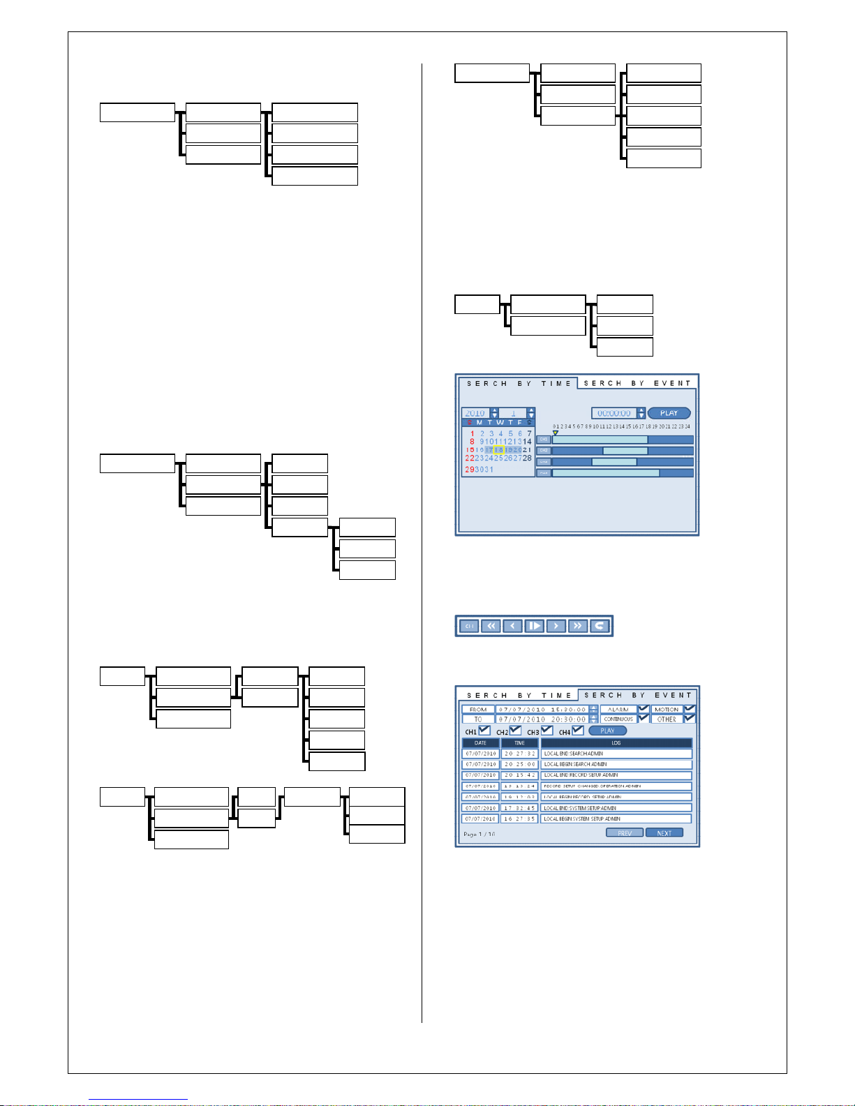
10. 1
SEARCH BY TIME
Click the right mouse button on the Live Display screen
and Click the
SEARCH
menu.
Click the date that user want.
Drag the
time bar by left mouse.
Click the
PLAY
menu.
Control play mode by control box.
10. 2. SEARCH BY EVENT
Click the
SEARCH BY EVENT
menu and each value for
query.
Click the
START
menu.
Double click event on the list.
Now system go
es to
play back mode.
SEARCH
SEARCH BY TIME
SEARCH BT EVENT
DATE
TIME LINE
TIME BOX
RECORD SETUP
RECORDING OPERATIONS
SIMPLE RECORDING
MANUAL RECORDING
SIZE
FPS
QUALITY
AUDIO
MANUL RECORD TIME
RECORD SETUP
RECORDING OPERATI
ONS
ADVANCE
RECORDING
MANUAL RECORDING
SETTING
ACTIVATION
TIMETABLE
CONTINUOUS
MOTION
ALARM
RECORD SETUP
RECORDING OPERATIONS
SIMPLE RECORDING
MANUAL RECORDING
RECORD QUALITY
RECORD SIZE
FPS
TIME TABLE
CONTINUOUS
MOTION
ALARM
RECORD SETUP
RECORDING OPERATIONS
ADVANCE
RECORDING
MANUAL RECORDING
SETTING
ACTIVATION
SIZE
FPS
QUALITY
AUDIO
ALARM
RECORD S
ETUP
RECORDING OPERATIONS
SIMPLE RECORDING
MANUAL RECORDING
RECORDING MODE
SCHEDULE MODE
PRE EVENT RECORDING TIME
POST EVENT RECORDING TIME
Page 12
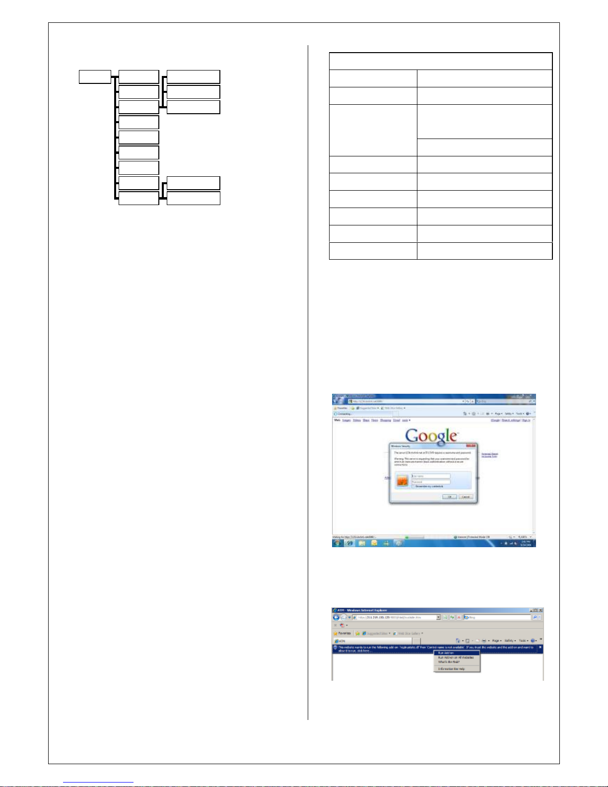
11.ARCHIVE
SETUP
Click the right mouse button on the Live Display
screen
AndClick
ARCHIVING
menu.
Select time and data then press PREVIEW button.
Backup information windows will be
pop
pedupPress PLAY button for check dat
a with play back mode.
PressOKto continue backup to external media.
Input title name for backup file and select device then
press start.
CAUTION!!!
Don’t insert any USB device during Archiving procedure.
12.
WEB CONNECTION SETUP
P
RELIMI
NARYBEFORE CONNECT
For using web connection, 554 and 8080 ports should be
done
port forwarding
set
in Router.
Refer the manual of Router for port
forwarding
setting
12.1
HOW TO CONNECT
Input the IP Address or URL of the DVR in the Internet
Ex
plorerAddress Bar.
When user uses the DDNS
service
, input the URL as below.
http://1234.dvrlink.net:8080
(web
port:8080)orhttp://1234.dvrlink.net
(web
port:80)
Default ID and password are
‘
ADMIN
’&’
1234’User need
s
to install
Active
-
X, click Run Add
-
on
WEB RA MINIMUM PC REQUIREMENT
CPU
P4 3.0 or Higher
RAM
512MB or Higher
Geforce MS
400, Radeon 7500 or
higher
VGA
Gefore 8 series or higher
VGA MEMORY
64MB
MONITOR
1280X1024
OS
WINDOW XP2
IE VERSION
IE6.0 or higher
NETWORK
100Mbps
DIRECT X
V7.0 or higher
ARCHIVING
FROM
TO
PREVIEW
ORIGINAL SIZE
CH SIZE
LOG SIZE
PROGRESS BAR
STOP
CH SELECT
Include Audio
Include
Log
DEVICE
MODE
START
Page 13
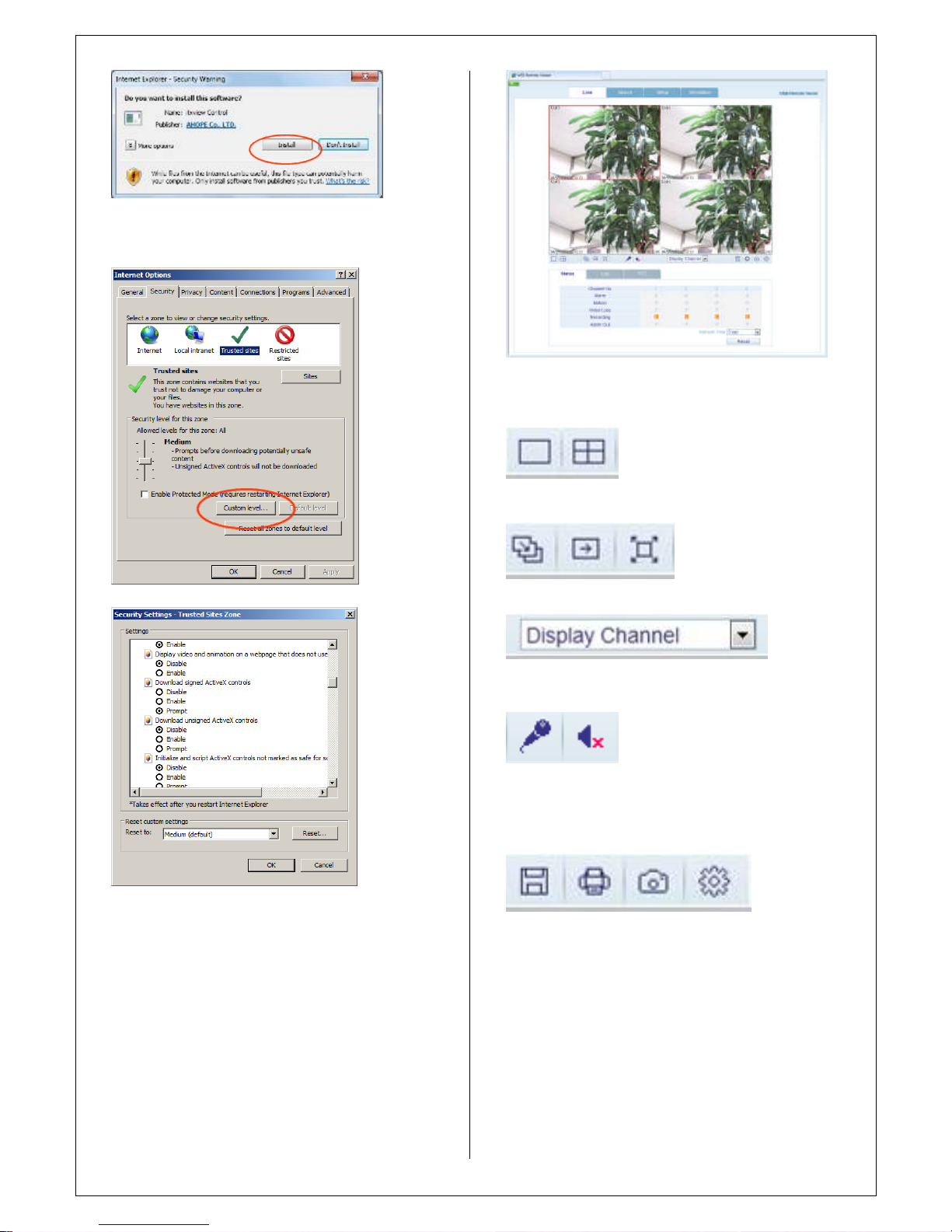
I
n case of, unable to install
active-X, User
needs
to check the
option of
active
X on IE security menu.
S
elect Enable for all ActiveX related options.
(ex, Download
signed ActiveX
control, Download unsigned
ActiveX cont
rol….)
12.2
LIVE MODE
Explanation of function button in LIVE mode
Select live division screen.
Move to next screen and make full screen
Select live channel.
Activate Mic to send a sound to DVR.
On/
Off Sound
from DVR
Save the live image.
Print the current screen.
Snapshot the current screen.
Setup [Render] and [Save Folder]
Status
:
Can see the current DVR status.
1.Alarm–Indicator will be
marked
when system detects
Page 14
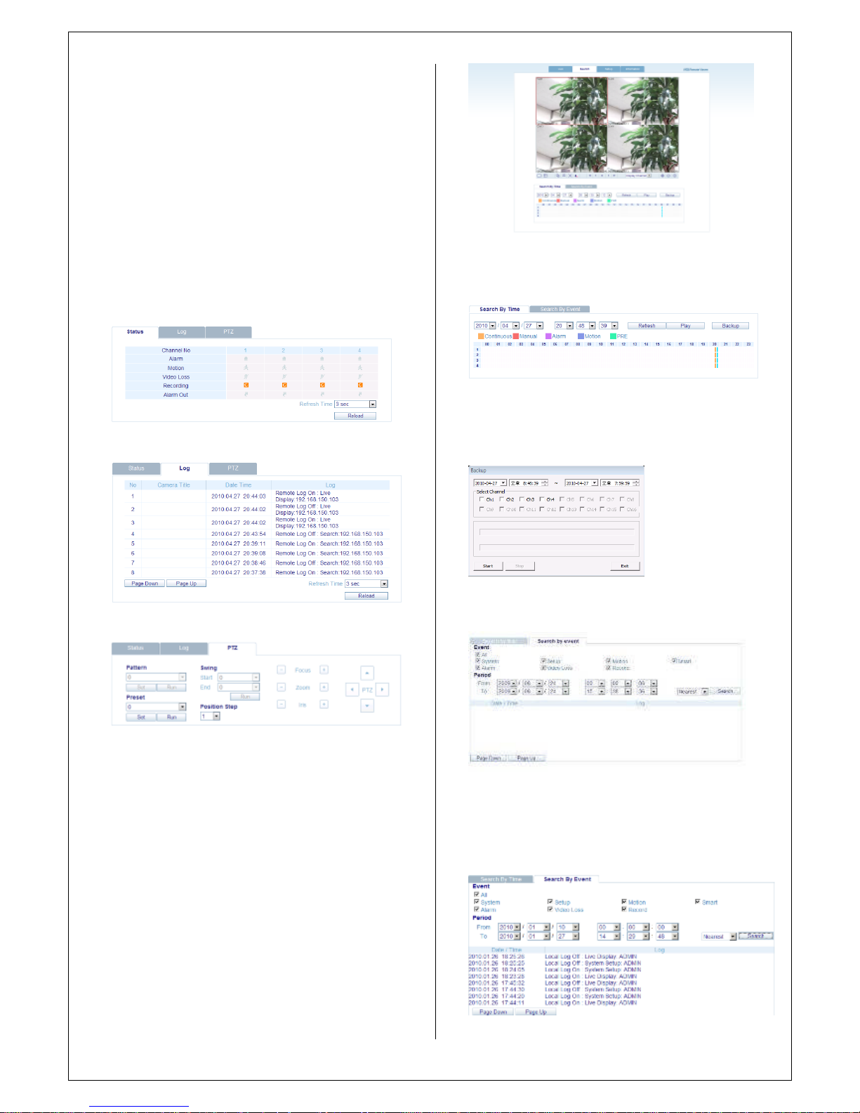
Alarm input.
2.Motion
-
Indicator will be
marked
when system detects
Motion3.Video Loss
-
Indicator will be
marked
when
system
detects
Alarm input.
4.Recording
–
Display current recording mode
(T:
Continuous
, M: Motion,A: Alarm recoding)
5.Alarm Out
-
Indicator will be
marked when
system detect
Alarm output.
6.Refresh Time
–
set inter
val of refresh or Reload for
manual refresh.
Log
:
Can see the log.
PTZ
:
Can control connected PTZ camera.
1.Pattern
–
move a camera among several preset position
2.Preset
–
set a position of camera view.
3.Swing–move a
camera
between two preset
points
.
12.3 SEARCH (Common time line search)
1.Select a time line on time table or set
an
exact time.
2.Then press
‘
Play’button
1.
Refresh:
Refresh the data.
2.
Play:
After select the date and time, can play the data.
3.
Backup:
Can backup special
channel and time.
12.4 SE
A
RCH BY EVENT
1.
Event:
Select necessary event to playback.
2. Period: Select the date an
d
time of Start to End.
3.
Search:
Startthe selected data.
4.S
elect a event on the list then DVR starting to playback
Page 15
the related
camera
’
s image
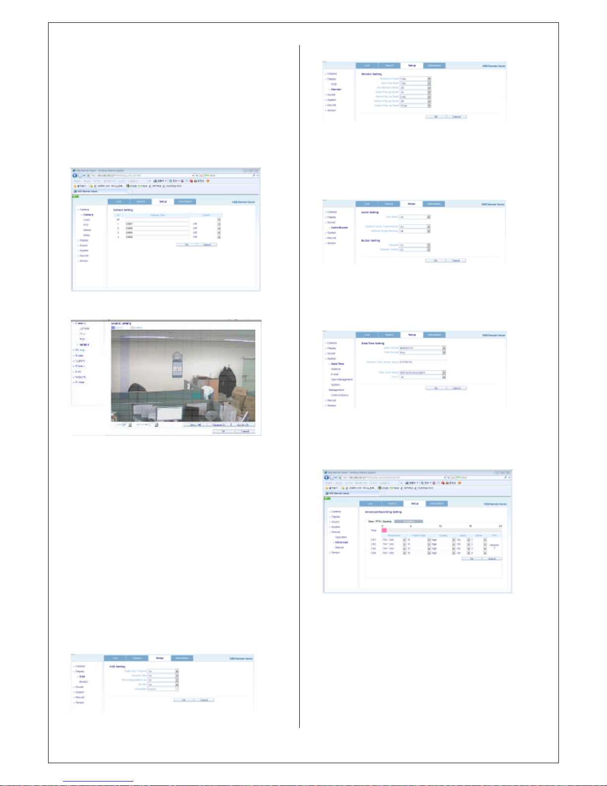
12.5 SETUP
MODE
All settings are same as DVR setup.
1.CAMER
A
user can configure
camera’
s attribute such as title, live color,
PTZ setup or motion
Motion setup for
detecting
motion
events
.1)
Select Motion menu tab.
2)Select a channel and
sensitivity.
3)Drag a mouse on image for select
detecting
area.4)
Press OK.
2
.
Display
1)OSD–User
allowedto
choose text display items over
the
image.
2)M
onitor-user can set dwell time for sequ
enc
e or spot,
and pop up fuction.
3
.
S
ound
1)Audio Setting
–
Select a live audio channel and
activation
2)Buzzer setting
–
Activate buzzer out for
event
notification
4
.
System
User can configur
e
DATE of system, check system
information and set controller.
5
.
Recording
User can configure the recording parameter,
Setting detail is
same as system.
6
.
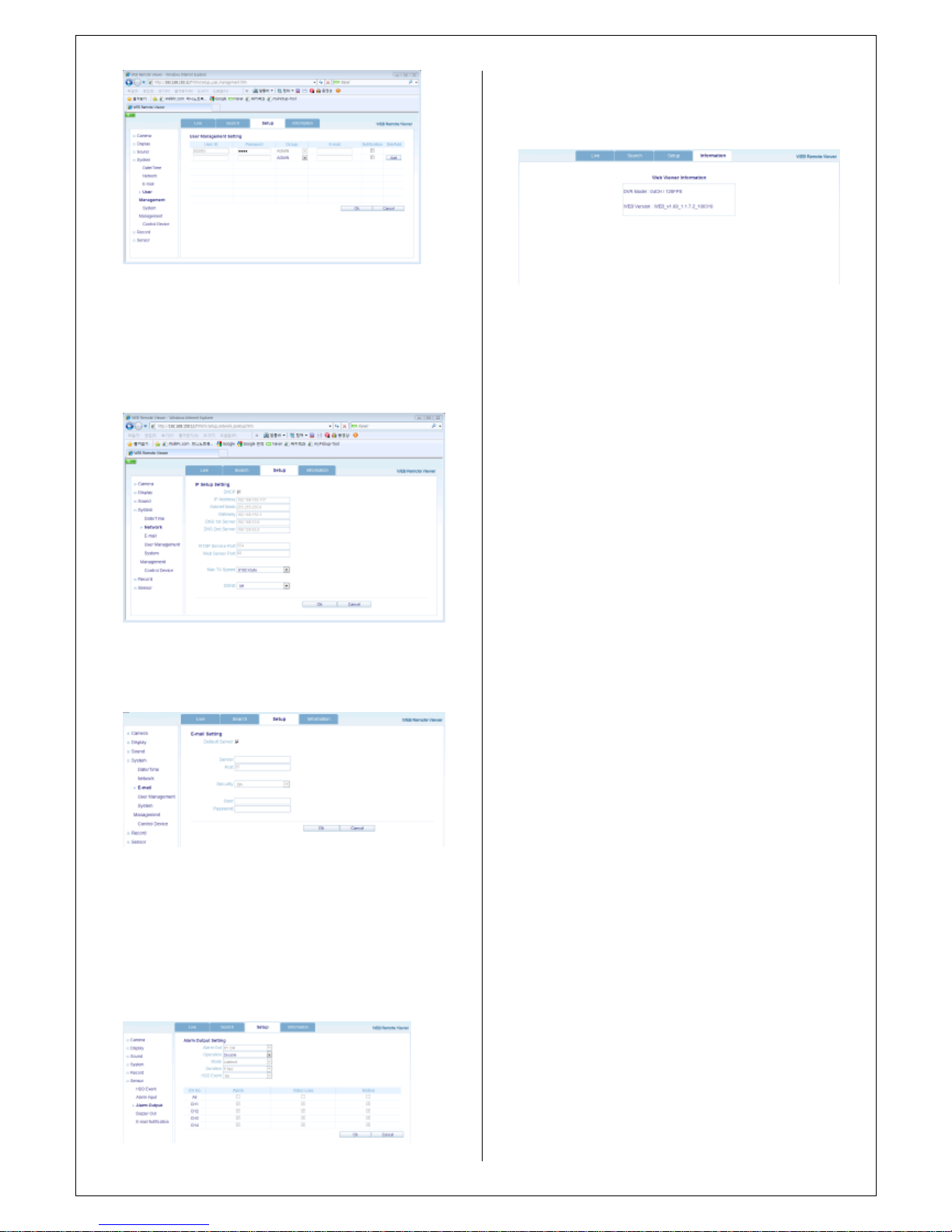
User
management
Users can add and delete
Page 16
7
.
Network
User can check the system
’
s network infor
ma
tion and
selectable
speed
level.B
ut IP settings are not allowed to
change on remote site.
N
etwork IP only can set on system.
For email notification, user can input the SMTP server detail
on below setup.
8
.
Sensor
Management can set all device option of Alarm in/out,
buzzerout for event notifcation.
(HDD EVENT,Alarm Input, Alarm output, Buzzer Out, Email
notificaion option)
All detail setup follow DVR system setup
12.6
INFORMATION
Check DVR model name and WEB version.
Page 17
1
3 SMART PHONE
CONNECTIONS
♣ I
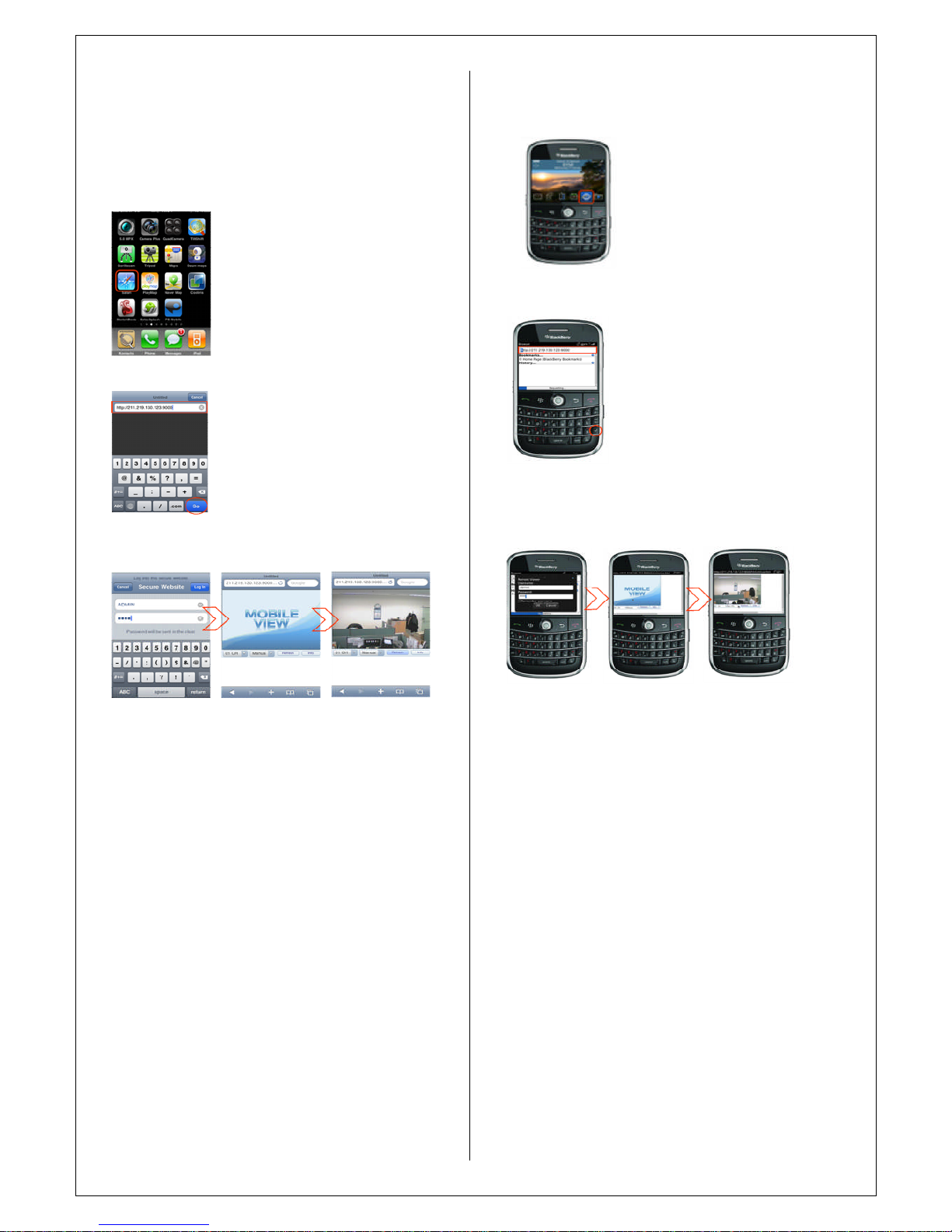
-
PHONE
1. Select the Safari browser
2.
Enter the IP address or URL to connect.
And Click the [GO] button.
3. Enter the User name and Password then use can see the
Image.
(Default ADMIN
/
1234)
Only allow to surveillance live view, not playback
and other
function.
You can also download the app
(Smart Viewer) from the app
store for iPhones andAndroid
phones.
♣
Blackberry
1. Select the
Web
browser
2.Enter the IP address or URL to connect.
And
press
the
Enter
button.
3. Enter the User name and Password then use can see the
Image.
(Default ADMIN / 1234)
 Loading...