

Clean Water Made Easy.
www.CleanWaterStore.com
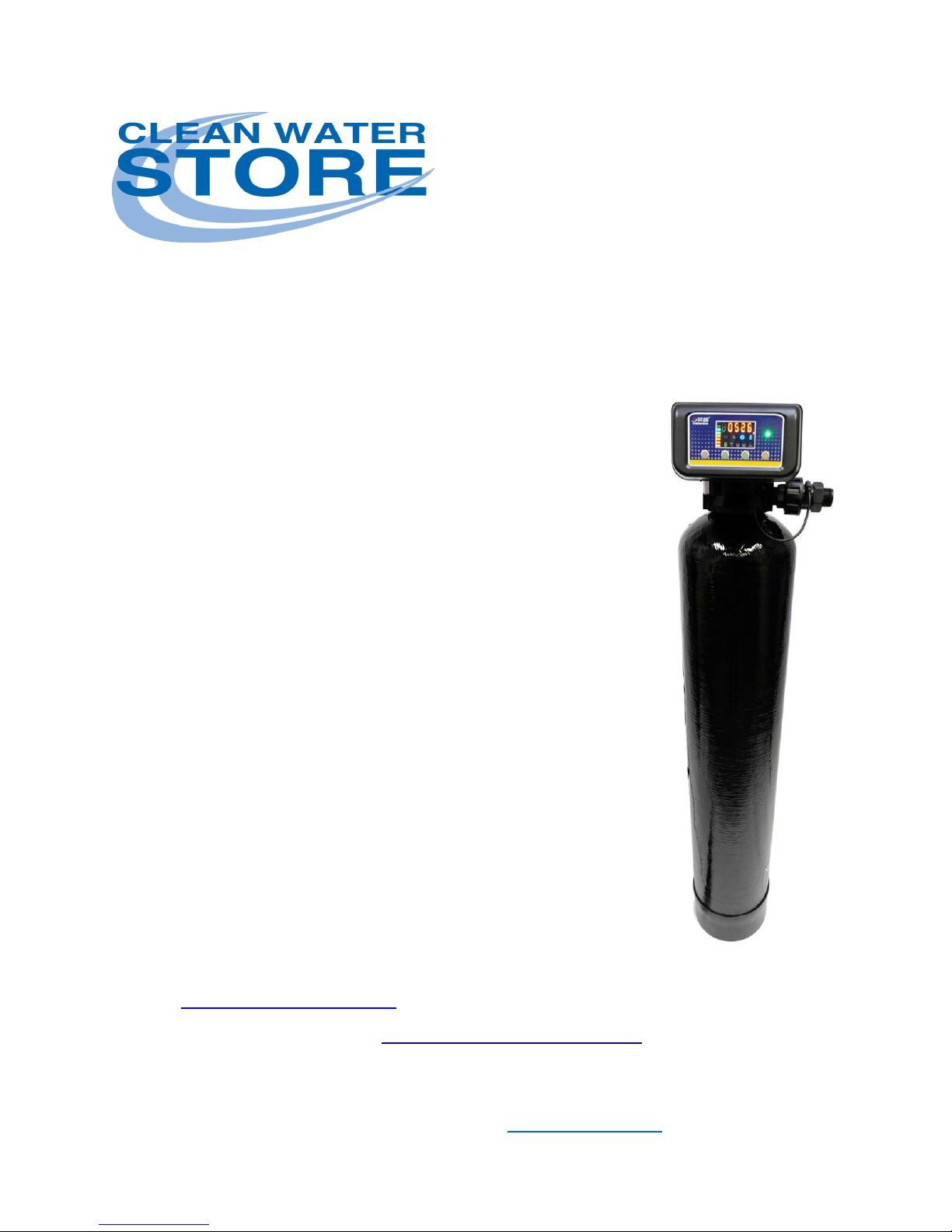
7500-S Carbon Backwash Filter Guide
Thank you for purchasing a Clean Water System!
With proper installation and a little routine maintenance your system will be
providing clean, odor-free water for many years.
Please review this start-up guide entirely before beginning to install your
system, and follow the steps outlined for best results.
Minimum pressure of 30 PSI recommended. Maximum pressure
recommended 80 PSI. For indoor installation.
Protect from sunlight, rain, and freezing.
MEDIA CONTAINS DUST. USE MASK TO AVOID BREATHING DUST.
OK to wet down media with spray bottle.
To connect drain line to drain, use an air-gap connection.
Questions?
Call us toll-free: 1-888-600-5426 or 1-831-462-8500
Email us: support@cleanwaterstore.com
See more information on our website: www.cleanwaterstore.com/resources
Page 1 7500-S Carbon Backwash Filter Guide www.cleanwaterstore.com rev102418

Contents
Packing Lists .................................................................................................................................................. 3
System Installation Steps Overview .............................................................................................................. 4
Pre-Installation .............................................................................................................................................. 4
Best Practices for Piping & Drain Installation ............................................................................................... 5
Installation of Your System in to Copper or Metal Piping Systems: ............................................................. 6
How Your Filter Works (Fig 2) ....................................................................................................................... 7
Parts Included with Control Valve ................................................................................................................ 8
Assembly and Installation Instructions .......................................................................................................... 8
Install By-Pass (Fig. 4) .................................................................................................................................. 10
Diagram of Installation Well Water (Fig. 5) ................................................................................................ 11
Diagram of Installation City Water (Fig. 6) .................................................................................................. 11
Programming Overview............................................................................................................................... 12
Program the 7500-S Valve........................................................................................................................... 14
Initial Backwash and Start-Up ..................................................................................................................... 15
Limited Warranty ........................................................................................................................................ 16
What to Do if Your Tank is Not Level Out of the Box
• Tank sizes for 2.5 Cubic Foot models and below: Your black filter tank base is not
glued to the bottom of your tank.
• Occasionally tank bases will become crooked during shipment.
• If you find that that your tank does not sit level on the floor, you can easily adjust
it by holding the empty tank and rapping it on a concrete or solid floor once or
twice to level.
Page 2 7500-S Carbon Backwash Filter Guide www.cleanwaterstore.com rev102418

Packing Lists
All systems include: 7500-S control valve; power supply; funnel for adding media through the top; drain
line flow control; and items included in one of the following options.
Find Your Filter Size model to see what is included:
Filter 0.75 cubic foot size 8” x 44” filter tank with distributor tube
8 lbs. filter gravel
0.75 cubic foot of Carbon Filter Media.
Filter 1.0 cubic foot size 9” x 48” filter tank with distributor tube
12 lbs. filter gravel
1 cubic foot of Carbon Filter Media
Filter 1.5 cubic foot size 10” x 54” filter tank with distributor tube
16 lbs. Filter gravel
1.5 cubic foot of Carbon Filter Media
Filter 2.0 cubic foot size 12” x 52” filter tank with distributor tube
20 lbs. filter gravel
2.0 cubic foot of Carbon Filter Media
Filter 2.5 cubic foot size 13” x 54” filter tank with distributor tube
35 lbs. filter gravel
2.5 cubic foot of Carbon Filter Media
Filter 3.0 cubic foot size 14” x 65” filter tank with distributor tube
40 lbs. filter gravel
3.0 cubic foot of Carbon Filter Media
Filter 4.0 cubic foot size 16” x 65” filter tank with distributor tube
50 lbs. filter gravel
4.0 cubic foot of Carbon Filter Media
Page 3 7500-S Carbon Backwash Filter Guide www.cleanwaterstore.com rev102418

System Installation Steps Overview
1. Put gravel in first, then Carbon Media.
2. Add ½ cup household bleach down center distributor tube and fill tank with clean water.
The longer it soaks while you are doing everything else, the better.
3. Make the plumbing connections from your existing system to the filter, installing a 3-valve
bypass around the 7500-S filter backwash control valve.
4. Screw on, attach the control head to the tank.
5. Install the drain Line tubing and external flow control assembly (if using for model 2.0 CF or
larger)
1. Plug in the power supply and program the valve.
2. Follow the instructions to put the system online, backwash and rinse several times and
check for leaks.
Pre-Installation
1. Review your packing list to make sure you have received all the parts before installation.
2. If you are going to be turning off the water to the house and you have an electric water
heater, shut off the power to the water heater before beginning installation.
3. Pick a suitable location for your filter system on a dry level spot where it won’t be exposed
to freezing temperatures, direct sunlight, wind or rain.
4. Get all of your plumbing parts together before beginning installation.
5. After the system is installed and running, your water may be discolored, or full of Carbon or
rust, especially if you have older or corroded piping. This typically clears up over a day or
two.
Page 4 7500-S Carbon Backwash Filter Guide www.cleanwaterstore.com rev102418

Best Practices for Piping & Drain Installation
1. See typical installation (Fig 5). The Carbon Backwash filter is installed after pressure tank
on well systems.
2. Install on a level floor or surface.
3. Filter system must be installed at least 10 feet ahead of inlet to water heater to prevent
damage due to back-up hot water or use a check valve to prevent hot water back-up.
4. DO NOT install the unit in an area of direct sunlight or expose to freezing.
5. Locate the unit near an unswitched, 120 volt / 60 Hz grounded electrical outlet.
6. Make sure to connect the IN pipe to the 7500-S inlet and the OUT pipe to the outlet and
install a 3 valve bypass around the 7500-S control valve.
7. Make sure there is a working gate or ball valve before the 7500-S Carbon Filter and also one
after as shown in Fig 4. The pressure gauges are optional. A hose bib (which is a faucet that
you can attach a garden hose to) is strongly recommended after the 7500-S Filter and
before the second ball valve, for rinsing and sampling water.
8. If you will be using copper piping, do not sweat the copper pipe directly on to the 7500-S
control valve. Avoid heating up the 7500-S control valve plastic with the torch.
9. The drain can run up above the control head and out to a drain, although this may require
installing a one way, flapper-stlye check valve.
10. Most plumbing codes require an air-gap connection, so that if your sewer or septic tank
backs up, it cannot cross connect with the drain tubing (if running tubing into the washing
machine drain pipe, for example)
11. Your 7500-S filter must be backwashed and rinsed 2 – 3 times on start-up. During the initial
backwashes and rinses, keep the valve after the system closed.
12. After backwashing and rinsing, open the hose bib after the system and before closed valve,
and run the water until it is clear.
Page 5 7500-S Carbon Backwash Filter Guide www.cleanwaterstore.com rev102418

Installation of Your System in to Copper or Metal Piping Systems:
If your new filter system is to be installed in a metal (conductive) plumbing system, i.e. copper or
galvanized steel pipe, the plastic components of the system will interrupt the electrical continuity of the
plumbing system.
As a result, any stray currents from improperly grounded appliances downstream or potential galvanic
activity in the plumbing system can no longer ground through the contiguous metal plumbing.
Some homes may have been built in accordance with building codes, which encouraged the grounding
of electrical appliances through the plumbing system.
Consequently, the installation of a bypass consisting of the same material as the existing plumbing, or a
grounded "jumper wire" bridging the equipment and reestablishing the contiguous conductive nature
of the plumbing system must be installed prior to your systems use.
This is simple and easy step to take if you are installing your water treatment system into copper
piping. A simple ground jumper wire with a pipe clamp can be purchased at any Home Center, or
hardware store etc. for a few dollars.
Fig 1
Page 6 7500-S Carbon Backwash Filter Guide www.cleanwaterstore.com rev102418

CARBON
How Your Filter Works (Fig 2)
Water enters the top of the tank and flows
down through the media and up the
distributor tube.
The downflow type Carbon Media Filter
removes Carbon and can be backwashed,
which cleans and re-classifies the Carbon
Media, preventing channeling.
During backwash the flow of water is
reversed and water flows down the
distributor tube and up through the media,
lifting and expanding the Carbon Media.
During the backwash the Carbon Media is
cleaned by the action of the water flowing
through it.
Page 7 7500-S Carbon Backwash Filter Guide www.cleanwaterstore.com rev102418

Parts Included with Control Valve
There are three fittings and three blue washers: Insert the Blue washers into the Inlet, Outlet,
and Drain ports, and screw in the fittings hand tight- the blue washer is making the positive seal,
do not over-tighten.
The male-threaded pipe fittings you connect to those female fittings will need Teflon tape and
paste.
Lubricant tube: use this on main tank O-ring and on Center Tube O-ring.
Main Tank O-ring: lubricate this and install into its’ groove on the bottom of the
control valve.
Spare center tube O-ring: There is already one in the valve, this is a second spare.
Cable and small screw driver: Most applications will not use this.
Meter Assembly: Also, most applications will not use this- you do not backwash a carbon, iron,
or neutralizer by gallons used, just by days.
Assembly and Installation Instructions
1. Wrap the top of distributor tube with electrical or painter’s tape so
that no gravel or media will go down the distributor tube when adding
the media. Sometimes, the systems are shipped with a black funnel
that fits over, and holds, the center tube in place.
2. Add the filter gravel that came with your order. You want the gravel to
cover the bottom distributor screen before adding the media.
3. Next add the media. The tank should be about 2/3rds full of media, do
not fill more than 2/3rds, even if there is some media left over.
Page 8 7500-S Carbon Backwash Filter Guide www.cleanwaterstore.com rev102418

4. Remove cap or tape from top of distributor tube. Be careful not to pull up distributor tube when
removing cap or tape.
5. Fill tank completely with water. This will allow the media to settle and reduce the need of purging
the air out of the tank later.
6. Add 1 cup of bleach for every size below 3.0 cubic foot (“CF”) of media and add an addition ½ for
each additional cubic foot. (4.0 size would get 1.5 cups bleach) Add a small amount of silicone
lubricant to the inner O-ring, where the distribution tube goes.
7. Some systems have a top screen, and some do not. If you have one, install it after you lube the Oring.
8. Add lubricant to main tank O-ring and screw on control valve until tight, by hand.
9. Do not use pipe-joint compound, vegetable oil, Teflon tape, or Vaseline or other petroleum greases
to lubricate tank threads (where the control valve threads on to the tank, do not lubricate those
threads).
10. Install INLET to Inlet port, and OUTLET from filter to the outlet (marked on control valve)
11. Install drain line flow control on drain line from 7500-S control valve.
12. Install piping to drain. Be sure to use an air gap so the drain is not connected directly to the drain or
sewer, to avoid cross connection.
13. Do NOT install check valve on drain, use air gap (a gap of air of 2” between end of drain tubing
coming from 7500-S control valve and opening to the drain pipe to sewer or septic tank.
NOTE: for 2.0 CF sizes and up, use 1” piping for drain. For sizes smaller than 2.0 CF, it is OK to use 5/8”
or ¾’ OD plastic tubing.
Page 9 7500-S Carbon Backwash Filter Guide www.cleanwaterstore.com rev102418

Install By-Pass (Fig. 4)
A 3-valve by-pass must be installed around 7500-S filter system, typically using PVC, PEX or other types
of piping. Don’t sweat copper directly on 7500-S or heat up plastic.
Flex lines may be used instead of the unions and 90’s shown. You could have slip by male fittings, then
flex lines, then male nipples.
This reduces the risk of plumbing it with too much pipe deflection- this must be avoided, as pipe
deflection will put undue pressure on the control valve threads which may then crack.
Page 10 7500-S Carbon Backwash Filter Guide www.cleanwaterstore.com rev102418

Diagram of Installation Well Water (Fig. 5)
Carbon
Carbon
Diagram of Installation City Water (Fig. 6)
Page 11 7500-S Carbon Backwash Filter Guide www.cleanwaterstore.com rev102418

Programming Overview
Note: Indicator locations may vary between models
1.
Menu/Confirm
2. Return/Immediate Backwash Start 11. Minutes
3.
Icon Indicating Programming Mode
4. Power Indicator 13. Fast Rinse
5. Time of day 14. Not used
6. Not Used 15. Not used
7. Not Used 16. Backwash
8.
Days remaining Until Backwash
9. Scroll up 18. Backwash cycle in process
10. Scroll down
12. Button Lock
17. In Service/Working
IMPORTANT: Before any operation, the valve menu must be unlocked. Press and
hold both the Up and Down buttons for approximately 5 seconds.
A sound will indicate the menu is unlocked. The menu will re-lock automatically
after 1 minute of inactivity.
Digital Display Icons and the four Service Buttons: In addition to the Dynamic
Display Stipe (explained below) there are eight digital icons on the display that
will indicate “where the valve is”. They are as follows (left to right, top row
bottom row):
Page 12 7500-S Carbon Backwash Filter Guide www.cleanwaterstore.com rev102418

Blue Motor Light (18): This light only comes on when the motor is advancing through the
backwash and rinse cycles.
Blue Wrench Icon (3): This light indicates that you are in the Programming Mode and can
change and set valve parameter values.
Blue Clock-face Icon (5): Indicates that the red digital display is showing the Current Clock Time.
That time is displayed in 24-hour format, i.e. 13:00 is 1:00 pm.
Blue Key Icon (12): Indicates that the buttons are locked; press and hold both scroll buttons to
unlock.
Green Service Icon (17): This, and the Dynamic Display Stripe will always be lit when valve is in
normal service mode.
Green Backwash Icon (16): arrow pointing up, underneath a green bar. This indicates that you
are programming the Backwash step, or that the filter is in backwash.
Brine Fill and Brine Rinse (15-14): These icons are for a softener application, they will never be
lit.
Green Rapid Rinse Icon (13): arrow pointing down above green bar. This indicates that you are
programming the Rapid Rinse step, or that the filter is in Rapid Rinse.
Dynamic Display Stripe: On the left side of the digital display, there are eight bars that light up
from red to green in a “going up” pattern. When the valve is in Service Mode, you will see that
bar display flashing. The blue Key Icon indicates that the buttons are “locked”. To unlock the
buttons, press and hold both scroll arrows. While locked, the menu also changes, scrolling
between the current clock time (blue Clock Icon will be lit) and the days remaining until the next
backwash.
Up and Down Arrows (9-10): When the Blue Key Icon is lit, press and hold both buttons to
unlock. When the Dynamic Display Stipe is blinking, pushing the up/down buttons has no effect.
When the blue Wrench icon is lit, pressing either up/down arrow will scroll through the menu
options. There is a total of eight Menu items (explained later).
Menu/ Confirm (1) button (the button on the far left, an empty square with an arrow pointing
left): This is the button you press (after you have unlocked the screen) that puts you in the
Service Menu, so you can program the valve. The first time you press it, the Dynamic Display
Stripe goes away, and the blue Wrench icon appears
Page 13 7500-S Carbon Backwash Filter Guide www.cleanwaterstore.com rev102418

Program the 7500-S Valve
There are eight menu items to set and confirm, to program your filter.
• Plug the valve in, and wait for the Service Screen to come on, and the Dynamic Service stripe to
start flashing.
• If the blue Key Icon is lit, press and hold both Scroll Buttons to unlock. The valve will beep, and
the key Icon will disappear.
• Press the Menu/Confirm button (far left) and the blue Wrench Icon will come on.
• You can now use either the scroll Up or Down buttons to stop at each of the 8 menu items you
will need to program.
• They are listed below in the order they appear (1-8) if you use the scroll up arrow and, when you
enter the programming, it will be at whichever Menu option that was last
programming mode was exited. The factory default screen is where this list starts (1):
displayed when the
1. Backwash Frequency (or, days between backwashes). For a Carbon filter, set to six days (0 hours, 0
minutes), to begin with, if your water is very bad, you may set it at five days.
2. Length of Backwash: set this to 10 minutes.
3. Length of Rinse: set this to 6 minutes
4. Current Clock Time: Set this to the current time. Uses 24-hour time, so 1:00 pm is 13:00.
5. Leave this set at zero, it is for a function not used in this application.
6. This will come set at 0 or 1, it does not need to be changed (not used)
7. Delay Backwash: Set this at the time you want the unit to backwash, every 5 or 6 days. We
recommend setting this at 2:00 am. Water cannot be used from the service side during the 18-20
minutes the control valve needs to cycle through the wash and rinse steps.
8. 485 Port Setting: this does not need to be adjusted or changed.
Page 14 7500-S Carbon Backwash Filter Guide www.cleanwaterstore.com rev102418

Initial Backwash and Start-Up
1 After programming, the system must be run through an initial backwash to bring
the system up to line pressure and flow. Additional backwashes (1-4 times,
depending on media and water quality) are also needed.
2 Close inlet valve B and outlet valve C, and open the bypass valve A. From the
initial valve menu, press the Manual/Return button to start a backwash cycle.
3 When the backwash icon is displayed, slowly open the inlet valve B just until you
hear water running. A slow amount of water and air will start coming out the
drain line. Open the valve a little more and notice a corresponding increase in
water out the drain line.
4 At a certain point in the backwash the water will turn dark gray or black. At this
point, unplug the power supply, so the valve stays in the backwash step with a
few minutes remaining.
5 Do not open the water any more, until the water flows out the drain line goes
from very black to cloudy. When it does, continue slowly opening the valve until
it is full open.
6 Plug the valve back in and let it finish the backwash and rinse cycle and return to
service. Open the first tap after the filter and run until clear.
7 The filter system will need to be backwashed and rinsed several times before all
the fines are gone and the media starts filtering normally.
Page 15 7500-S Carbon Backwash Filter Guide www.cleanwaterstore.com rev102418

Limited Warranty
We warrant this water filter/ softener/ conditioner, when installed according to factory recommendations, to be
free from defects in materials and workmanship as follows:
This water conditioner unit is comprised of the finest industry components available. Each individual component
used in the assembly of our equipment is covered by the original equipment manufacturer’s warranty. All
components, except those specifically listed below, are warranted for a period of one (1) year from date of
installation to the original purchaser to be free of defects in materials and workmanship subject to the
manufacturer’s conditions and/or the conditions shown below.
----------Mineral Tanks----------
The fiberglass, polyglass or composite mineral tanks used in the assembly of this unit are warranted to be free of
defects in materials and workmanship for a period of ten (10) years on 6” – 13” size tanks, and five (5) years on 14”
and larger size tanks used for softener/filtration applications, subject to the manufacture’s conditions and/or the
conditions shown below. Warranty does not cover exposure to weather, freezing, fractures caused by external
impact, or exposure to vacuum.
----------Control Valves----------
The CWS control valve is warranted to be free of defects in materials and workmanship for a period or one (1)
years, subject to the manufacturer’s conditions and/or the conditions shown below.
----------Conditions----------
1. This warranty only covers water conditioners installed for residential use. Water conditioners installed for
commercial or industrial applications are guaranteed for one (1) year from the date of installation.
2. Installation must be made in accordance with legal or local codes and manufacturer’s recommendations.
3. Failure must not result from exposure to weather, rodents, misuse, alteration, fire, lightning, power surges or
neglect.
4. Water pressure must not exceed 100 PSI and water temperature must not exceed 100 degrees.
5. Subject to the above terms and conditions we will replace and/or repair, at our option, any parts of the water
conditioner found defective in materials and workmanship. Defective parts must be returned, freight pre-paid for
repair or replacement.
6. This warranty does not cover labor, shipping charges, damages caused by delays of consequential damages or
other causes beyond our control. Warranty does not cover pipes, fixtures or appliances. Warranty extends to the
actual water conditioner components only.
7. This warranty is to the original purchaser and is not transferable after the third year to any subsequent
owner(s).
8. No other guarantees or warranty, expressed or implied, is applicable to our product. No repair or replacement
made under the terms of the warranty shall extend this warranty.
Page 16 7500-S Carbon Backwash Filter Guide www.cleanwaterstore.com rev102418
 Loading...