

Clean Water Systems 5900-BT Neutralizer Operation & Maintenance Manual
Clean Water Made Easy
5900-BT Neutralizer
Operation & Maintenance
Manual
Thank you for purchasing a Clean Water System! With
proper installation and a little routine maintenance your
system will be providing neutral pH water for many years.
Please review this start‐up guide entirely before beginning
to install your system, and follow the steps outlined for
best results.
www.cleanwaterstore.com
CALCITE MEDIA CONTAINS DUST. USE PAPER MASK AND
VENTILATE TO AVOID BREATHING DUST (Use a spray bottle
to wet the media down).
Helpful Videos:
https://www.youtube.com/channel/UC415QpvlRz‐
YAntxlMieI2w/videos
Questions?
Call us toll‐free: 1‐888‐600‐5426 or 1‐831‐462‐8500
Email us: support@cleanwaterstore.com
See more information on our website: www.cleanwaterstore.com/resources

Table of Contents
Packing List .................................................................................................................................................... 3
How Your Neutralizer Works ........................................................................................................................ 4
System Installation Recommendations ........................................................................................................ 5
Pre‐Installation .............................................................................................................................................. 5
Best Practices for Piping & Drain Installation ............................................................................................... 6
Fig. 3: Typical Neutralizer 5900‐BT piping installation ................................................................................. 7
Installation Steps Overview .......................................................................................................................... 8
Add the Neutralizer Media and Install 5900‐BT Backwash Valve on Tank ................................................... 9
Attach the Bypass ....................................................................................................................................... 11
Program Your Valve .................................................................................................................................... 12
See Historical Data and Real Time Flow Rate ............................................................................................. 14
Start Up of Neutralizer Filter: Overview ..................................................................................................... 14
Detailed Steps to Starting Up Neutralizer Filter System ............................................................................. 15
Installing and Using the Optional Legacy View App .................................................................................... 16
Battery Back‐up (9 Volt Battery Required) ................................................................................................. 20
How to Start A Manual Backwash ............................................................................................................... 20
Maintaining Your Neutralizer ...................................................................................................................... 21
How to Add Calcite Media .......................................................................................................................... 21
When to Use Calcite Blends ........................................................................................................................ 22
Troubleshooting the 5900‐BT Neutralizer Filter ......................................................................................... 24
Error Codes ................................................................................................................................................. 24
pH is Too High ............................................................................................................................................. 24
pH is Too Low .............................................................................................................................................. 25
White Spots on Fixtures and Glasses .......................................................................................................... 25
Replace Seals and Spacers Inside 5900‐BT Control .................................................................................... 26
Valve Body Assembly S900‐BT .................................................................................................................... 27
Control Valve Assembly 5900‐BT ................................................................................................................ 28
Water Filters Limited Warranty .................................................................................................................. 29
Font used in paper guide is small, to save paper. PDF version available on our website.

5900S Neutralizer Operation & Maintenance Manual
Packing List
All systems include: 5900S control valve, bypass assembly with 1” connector yoke, power
supply, top screen, and media funnel for adding the Neutralizer media.
Neutralizer Filter 1.0 cubic foot size
10” x 44” filter tank with distributor tube
9 lbs. Filter gravel and 0.75 cubic foot of Neutralizer media
Neutralizer Filter 1.0 cubic foot size Short Tank
13” x 30” filter tank with distributor tube
12 lbs. Filter gravel and 1 cubic foot of Neutralizer media
Neutralizer Filter 1.5 cubic foot size
10” x 54” filter tank with distributor tube
16 lbs. Filter gravel and 1.5 cubic foot of Neutralizer media
Neutralizer Filter 2.0 cubic foot size
12” x 52” filter tank with distributor tube
20 lbs. Filter gravel and 2.0 cubic foot of Neutralizer media
Neutralizer Filter 2.5 cubic foot size
13” x 54” filter tank with distributor tube
35 lbs. Filter gravel and 2.0 cubic foot of Neutralizer media
What to Do if Your Tank is Not Level
Your black filter tank base is not glued to the bottom of your tank. Occasionally tank bases will
become crooked during shipment. If you find that that your tank does not sit level on the
floor, you can easily adjust it by holding the empty tank and gently knocking the base on a
concrete or solid floor once or twice to level it.
Page 3 www.cleanwaterstore.com Rev 110117
5900S Neutralizer Operation & Maintenance Manual
How Your Neutralizer Works
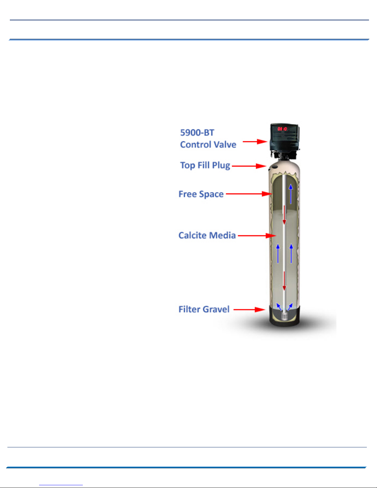
See Fig 1 on the right. In your
Neutralizer, the water enters the
top of the tank (red arrows) and
flows down through the media and
up the distributor tube (blue
arrows).
The downflow type Neutralizer
raises the pH of your water and can
be backwashed, which cleans and
re‐classifies the Calcite, preventing
channeling.
During backwash the flow of water
is reversed and water flows down
the distributor tube and up through
the media, lifting and expanding
the Calcite media.
During the backwash the Calcite is
cleaned by the action of the water
flowing through it.
Page 4 www.cleanwaterstore.com Rev 110117

5900S Neutralizer Operation & Maintenance Manual
System Installation Recommendations
1. Verify that you have received all parts and there are no damaged or missing parts.
2. Put gravel in first, then Neutralizer Media. Fill tank with clean water. Allow to soak for
at least one hour up to 24 hours.
3. Make the plumbing connections from your existing system to the bypass assembly,
installing extra valves, unions, pressure gauges and hose bibs as needed.
4. Do not use copper piping BEFORE the neutralizer, best to use PVC or PEX. OK to use
copper AFTER the neutralizer filter.
5. Attach the control head to the tank, and to the bypass assembly.
6. Install the Drain Line tubing and Drain Line Tubing Flow Control button (Internal for
models 2.0 CF and less, or External flow control assembly for models 2.5 CF and greater)
7. Plug in the power supply and program the valve.
8. Follow the instructions to put the system online and to verify the system is leak‐free.
Pre-Installation
1. Review your packing list to make sure you have received all the parts before
installation.
2. If you are going to be turning off the water to the house and you have an electric water
heater, shut off the power to the water heater before beginning installation.
3. Pick a suitable location for your filter system on a dry level spot where it won’t be
exposed to freezing temperatures, direct sunlight, wind or rain.
4. Get all of your plumbing parts together before beginning installation.
5. After the system is installed and running, your water may be discolored, or full of
sediment or rust, especially if you have older or corroded piping. This typically clears
up over a day or two.
Page 5 www.cleanwaterstore.com Rev 110117
5900S Neutralizer Operation & Maintenance Manual
Best Practices for Piping & Drain Installation
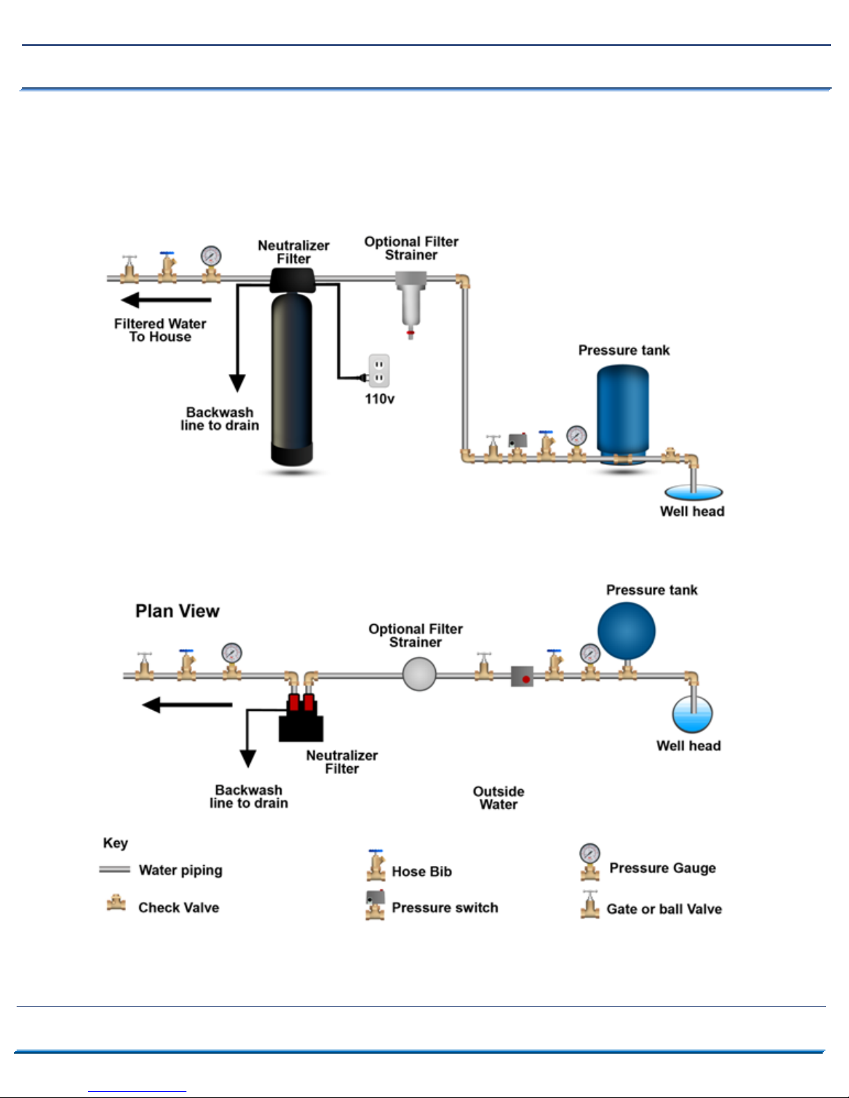
1. See typical installation diagram (Fig 3 on next page). In well water applications, the
neutralizer filter must be installed after the pressure tank.
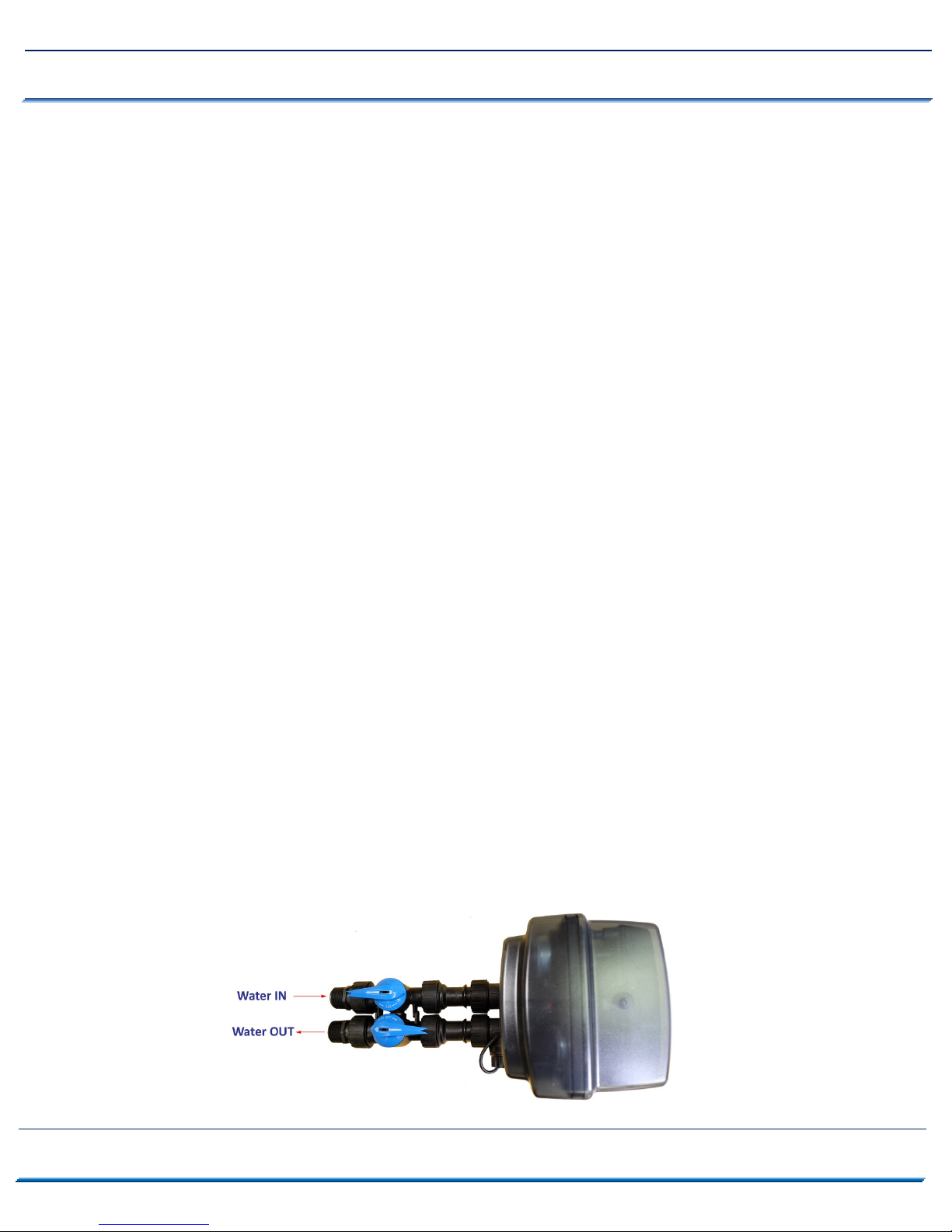
2. Make sure to connect the IN pipe to the 5900‐BT inlet and the OUT pipe to the outlet. As
you face the 5900‐BT control from the front, the water enters on the right and exits on the
left. From the back (see Fig 3) the water enters on the left. The inlet and outlet are
attached to the bypass valve, which is marked with arrows as well.
3. Make sure there is a working gate or ball valve before the Neutralizer Filter and also one
after as shown in Fig 3. The pressure gauges are optional and perhaps not necessary but a
hose bib (which is a faucet that you can attach a garden hose to) is strongly recommended
after the Neutralizer Filter and before the second ball valve. This makes it easy to rinse
your Neutralizer Filter on start‐up and gives you a place to test the water before the house
pipes.
4. If you will be using copper piping, do not sweat the copper pipe directly on to the 5900‐BT
control valve. Avoid heating up the 5900‐BT control valve plastic with the torch.
5. You do not need unions to install your 5900‐BT control valve. If you need to remove it, the
5900‐BT has quick‐release couplings that make it easy to put the Sediment filter on by‐pass
and remove the filter system from the piping.
6. The drain line tubing (not supplied) is connected to a drain from the drain outlet using
flexible 5/8” ID tubing. The drain can run up above the control head and out to a drain.
Most plumbing codes require an air‐gap connection, so that if your sewer or septic tank
backs up, it cannot cross connect with the drain tubing (if running tubing into the washing
machine drain pipe, for example).
Page 6 www.cleanwaterstore.com Rev 110117
5900S Neutralizer Operation & Maintenance Manual
Fig. 3: Typical Neutralizer 5900-BT piping installation
Page 7 www.cleanwaterstore.com Rev 110117

5900S Neutralizer Operation & Maintenance Manual
Installation Steps Overview
nstall on a level floor or surface.
1. I
2. Un
3. D
4. L
5. Check for distance and proper drain installation (e.g. floor drain, washing machine standpipe).
6. N
7. C
it must be installed at least 10 feet ahead of the inlet to a water heater to prevent damage due to
back‐up hot water or use a check valve to prevent hot water back‐up.
O NOT install the unit in an area of direct sunlight or where freezing temperatures may occur.
ocate the unit near an unswitched, 120 volt / 60 Hz grounded electrical outlet.
Determine type and size of piping required for filter connection (e.g. copper, galvanized, PVC
plastic).
ote: If household plumbing is galvanized and you intend to make the installation with copper
obtain di‐electric unions to prevent dissimilar metal corrosion.
aution: If sweat soldering copper pipe (remember to always use lead free solder and flux), cover
yoke and bypass valve with wet rags to prevent heat damage to connections and control valve. If
using PVC or plastic pipe, primers and solvent cements specifically recommended for use with
potable water are required.
Start Installation
ake sure to connect the IN pipe to the
1. M
you face the 5900‐BT control from the front, the water enters on the right and exits on the left.
From the back the water enters on the left. The inlet and outlet are attached to the bypass valve,
which is marked with arrows as well.
2. M
ake sure there is a hose bib installed after the system, and a working gate or ball valve before the
filter system and also one after as shown in Fig 2 and 3. The pressure gauges are optional (although
strongly reccomended) but a hose bib (which is a faucet to which you can attach a garden hose) is
strongly recommended after the Neutralizer Filter.. before the second ball valve. This makes it
easy to rinse your new 5900‐BT on start‐up and gives you a place to test the water before it enters
your household plumbing.
Page 8 www.cleanwaterstore.com Rev 110117
inlet and the OUT pipe to the outlet (see previous page). As

5900S Neutralizer Operation & Maintenance Manual
3. You do not need unions to install your 5900‐BT control valve. If you need to remove it, the 5900‐BT
control valve has quick‐release couplings that make it easy to put the 5900‐BT on by‐pass and
remove the filter system from the piping.
4. T
he drain line tubing is connected to a drain from the drain outlet using flexible 5/8” ID tubing.
Note that the drain line can run up above the 5900‐BT control and into a drain, it does not have to
drain down, as the filter backwashes under line pressure.
5. Most plumbing codes require an air‐gap connection for the drain line tubing, so that if your sewer or
septic tank backs up, it cannot cross connect with the drain tubing.
6. T
here are two styles of funnel that we ship, depending on availability; you get either the blue or
black funnel.
Add the Neutralizer Media and Install 5900-BT Backwash Valve on Tank
f a blue funnel, cover the top of the distributor tube with black electrical tape, duct tape or masking
1. I
tape so that no gravel or media will go down the distributor tube when adding the media. Leave
lded tab of tape so you can easily pull off the tape after filling the tank.
fo
a
2. Ma
3. A
4. If you received Corosex or Flomag (magnesium oxide) in your
5. Fi
6. R
ke sure you “test fit” the distribution tube, and find the divot that
keeps the tube centered, before adding the gravel and media. Hold the
tube center until there is enough gravel and media to support the tube.
The top of the distributor tube should be level with the top opening of
the filter tank and not stick up higher than the top of the tank.
dd the filter gravel that came with your order. The gravel should cover
the bottom distributor screen before adding the Calcite filter media.
shipment (used with a pH of below 6), you can now mix it
together with the Calcite before adding the blend into th
nk. It does not have to be exact, but we recommend mixing
ta
them together in a bucket, and adding into the tank until it is
2/3rds full, do not fill past 2/3rds.
ll tank completely with water and allow to soak for at least 1
hour up to 24 hours before you hook it up to piping.
emove tape from top of distributor tube. Be careful not t
pul
l up distributor tube.
e
o
Page 9 www.cleanwaterstore.com Rev 110117
 Loading...