

UNDERCOUNTER DISHMACHINES
DRAFT
INSTALLATION, OPERATION,
AND SERVICE MANUAL
HT-E
HT-E Manual • 07610-004-64-85-A


REVISION HISTORY
Revision
Letter
A DRAFT JH N/A DRAFT
Revision
Date
Made by Applicable ECNs Details
iii

NOMENCLATURE
HT-E
Undercounter dishmachine; high-temperature, hot-water
sanitizing, with a booster tank, drain pump, and
detergent and rinse-aid dispensers.
The manufacturer provides
technical support for the
dishmachine detailed in
this manual. We strongly
recommend that you refer to
this manual before making a
call to our technical support
sta. Please have this manual
open when you call so that our
sta can refer you, if necessary,
to the proper page. Technical
support is not available
on holidays.
Contact technical support tollfree at 1-888-800-5672.
Technical support is available
for service personnel only.
iv

TABLE OF CONTENTS
GUIDES
Symbols ...................................................................................................................................... 1
Abbreviations .............................................................................................................................. 1
SPECIFICATIONS
Machine Dimensions .................................................................................................................. 2
Operating Parameters ................................................................................................................ 3
Electrical Requirements ............................................................................................................. 4
INSTALLATION
Installation Instructions ............................................................................................................... 5
Inspection......................................................................................................................... 5
Unpacking ........................................................................................................................ 5
Plumbing .......................................................................................................................... 5
Water Supply Connections .............................................................................................. 5
Pressure Regulator .......................................................................................................... 6
Shock Absorber ............................................................................................................... 6
Connecting the Drain Line ............................................................................................... 6
Plumbing Check ............................................................................................................... 6
Electrical Power Connections .......................................................................................... 7
Voltage Check .................................................................................................................. 7
Surrounding Area ............................................................................................................. 7
Thermostats ..................................................................................................................... 8
Chemical Feeder Equipment ........................................................................................... 8
Priming Chemical Feeder Pumps .................................................................................... 8
Leveling............................................................................................................................ 8
OPERATION
Operating Instructions ................................................................................................................ 9
Preparation ......................................................................................................................9
Filling the Wash Tank ....................................................................................................... 9
Ware Preparation ............................................................................................................. 9
Washing a Rack of Ware ...............................................................................................10
Operational Inspection ................................................................................................... 10
Alarms ............................................................................................................................ 10
Draining.......................................................................................................................... 11
Shutdown & Cleaning .................................................................................................... 11
Deliming ......................................................................................................................... 13
Detergent Control...........................................................................................................14
v

TABLE OF CONTENTS
MAINTENANCE
Preventative Maintenance ........................................................................................................ 15
Drain Pump Cleanout ............................................................................................................... 15
TROUBLESHOOTING
Troubleshooting ........................................................................................................................ 16
PARTS
Tub & Frame ............................................................................................................................. 18
Electrical ................................................................................................................................... 20
Hoses ....................................................................................................................................... 22
Wash & Rinse Arms .................................................................................................................. 24
Plumbing Options ..................................................................................................................... 26
Miscellaneous Parts ................................................................................................................. 27
SCHEMATICS
208-230 V, 60 Hz, 1 Phase ....................................................................................................... 28
vi
GUIDES
NOTICE
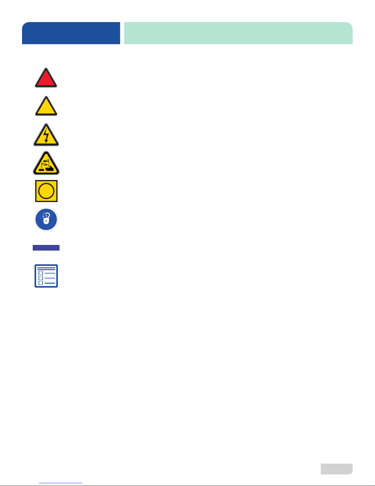
SYMBOLS
- Risk of Injury to Personnel
!
WARNING
- Risk of Damage to Equipment
!
CAUTION
- Risk of Electrical Shock
- Caustic Chemicals
- Reference Data Plate
i
GUIDES
- Lockout Electrical Power
- Important Note
- Instructions Hyperlink
ABBREVIATIONS & ACRONYMS
ANSI - American National Standards Institute
CFM - Cubic Feet per Minute
dBA - Decibels Adjusted
GHT - Garden Hose Thread
GPH - Gallons per Hour
GPM - Gallons per Minute
GPG - Grains per Gallon
HP - Horse Power
Hz - Hertz
ID - Inside Diameter
kW - Kilowatts
MCA - Minimum Circuit Ampacity
MOP - Maximum Overcurrent Protection
NFPA - National Fire Protection Association
NPT - National Pipe Thread
OD - Outside Diameter
PRV - Pressure Regulating Valve
PSI - Pounds per Square Inch
V - Volts
07610-004-64-85-A
1
SPECIFICATIONS
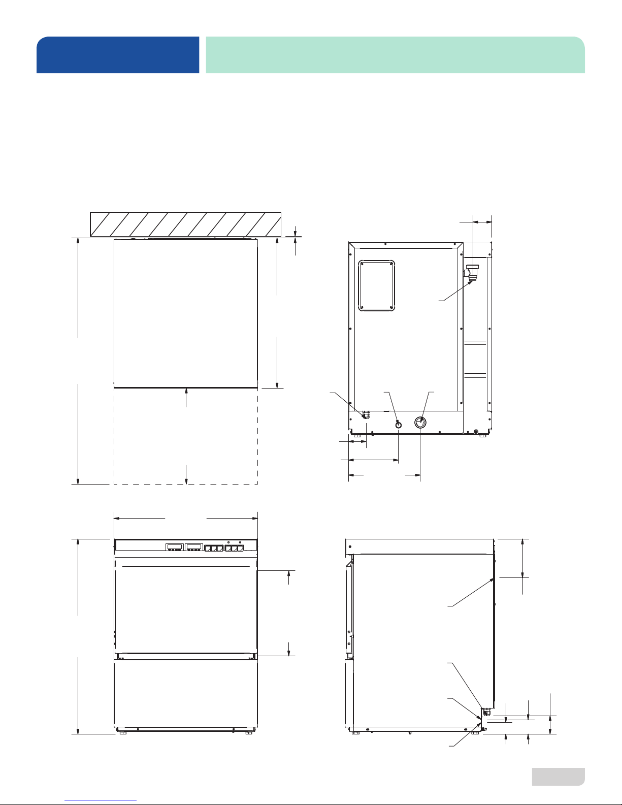
LEGEND
A - Electrical Connection
B - Water Inlet (connection actually at end of pre-installed hose)
C - Drain Connection
D - Chemical Connection
All dimensions from the floor can be increased
2” using the machine’s adjustable feet.
]
m
/2
m
1
9
0
2
4
0
1
[
MACHINE DIMENSIONS
[79 mm]
]
m
/4
m
1
7
[
]
m
4
/
m
3
9
4
2
2
TOP BACK
[6
B
3 1/8
A
N
]
E
P
m
4
/
O
m
3
0
R
5
0
1
O
[4
O
D
23 3/4
[603 mm]
4
]
m
/8
m
1
6
2
1
3
[8
FRONT SIDE
1
[76 mm]
[210 mm]
E
]
C
m
N
A
m
R
6
A
5
E
[3
L
C
3
8 1/4
D
11 7/8
[302 mm]
C
B
A
C
]
m
8
/
m
3
2
6
6
[1
]
]
]
8
m
/
8
/
3
7
m
2
8
1
[4
m
m
3
m
6
m
0
[7
[6
07610-004-64-85-A
D
2

SPECIFICATIONS
NOTICE
OPERATING PARAMETERS
Operating Capacity (without Load Time): HT-E
Racks per Hour 32
Dishes per Hour 800
Glasses per Hour 1152
Operating Capacity (with Load Time):
Racks per Hour 25
Dishes per Hour 625
Glasses per Hour 900
Tank Capacity (Gallons):
Wash Tank XX
Booster Tank XX
Electrical Loads (as applicable):
Wash Motor HP 3/4
Wash Heater kW (208 V) 3.2
Wash Heater kW (230 V) 4.5
Booster Heater kW (208 V) 3.9
Booster Heater kW (230 V) 5.5
i
Always refer to the machine data plate for specic electrical and water requirements.
The material provided on this page is for reference only and is subject to change
without notice.
Sound Level:
Workplace-related Emission Value (dBA) 66
Water Temperatures (°F):
Minimum Wash Temperature 150
Minimum Rinse Temperature 180
Minimum Incoming Water Temperature 110
Water Consumption:
Gallons per Rack 0.69
Gallons per Hour 22.1
Other Water Requirements:
Water Flow Pressure (PSI) 20 ± 5
Flow Rate Minimum (GPM) 4.6
Water Line Connection Size 3/4" GHT
Water Line Size (NPT) 1/2"
Drain Line Size (NPT) 1" ID
1 3/8" OD
07610-004-64-85-A
3
SPECIFICATIONS
NOTICE
i
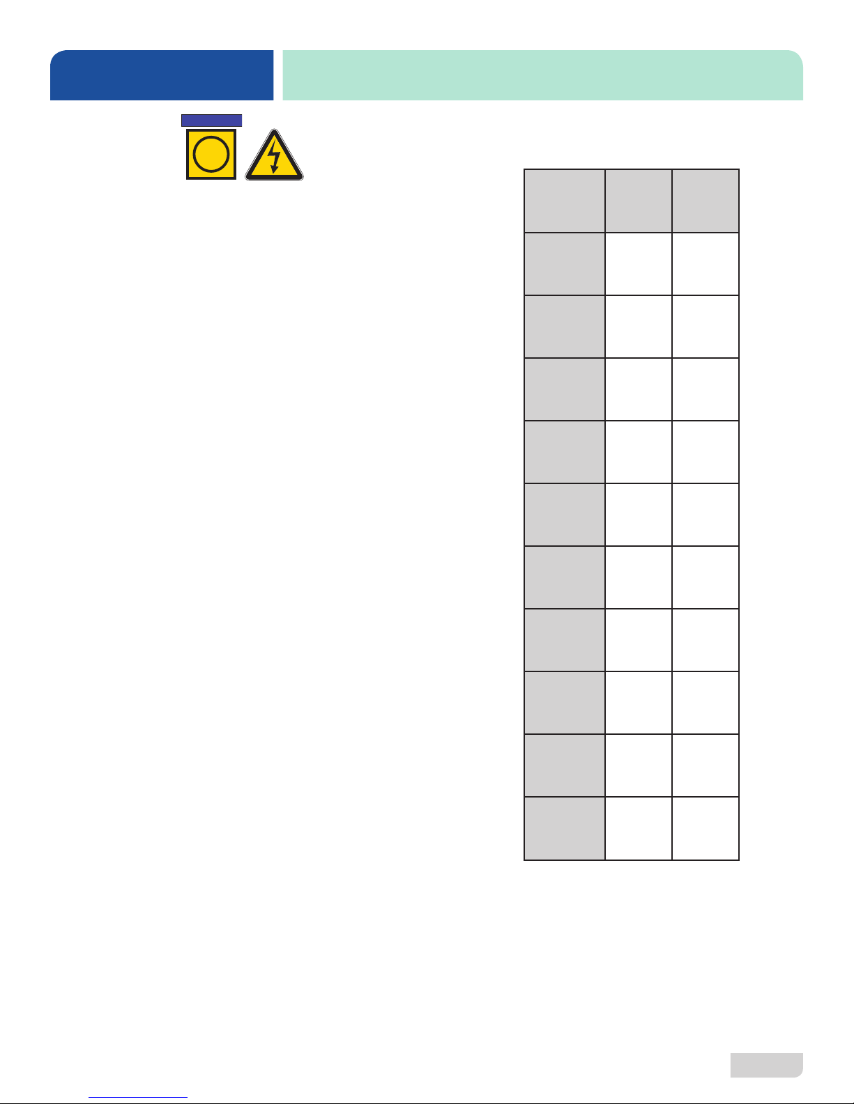
ELECTRICAL REQUIREMENTS
Electrical Characteristics
HT-E
All electrical ratings provided in this manual are for reference
only. Always refer to the machine data plate to get exact electrical
information for this machine. All electrical work performed on
machines should be done in accordance with applicable
local, state, territorial, and national codes. Work should only
be performed by qualied electricians and authorized service
agents.
Note that all electrical wiring used in the HT-E must be rated, at
a minimum, for 212 °F (100 °C), and that only copper conductors
must be used.
Where applicable, heating element amperage draws have been
adjusted for the assumed input voltage. The manufacturer
assumes incoming voltages will be either 208 or 230 Volts. Some
heating elements used in the machines are rated for other voltages,
such as 240 Volts and 480 Volts. Always verify the amperage
draw of the machine in operation when sizing circuit protection.
Available Electrical Characteristics:
• 208 V, 60 Hz, Single-phase
• 230 V, 60 Hz, Single-phase
VOLTS 208 230
PHASE 1 1
FREQ 60 60
WASH
MOTOR
AMPS
DRAIN
MOTOR
AMPS
RINSE
MOTOR
AMPS
WASH
HEATER
AMPS
BOOSTER
HEATER
AMPS
3.8 A 3.8 A
0.3 A 0.3 A
1.8 A 1.8 A
15.2 A 16.8 A
21.7 A 24.0 A
07610-004-64-85-A
TOTAL
LOAD
MCA 26.8 A 28.8 A
MOP 30.0 A 30.0 A
25.8 A 27.8 A
4

INSTALLATION
Shut-off
Adapter AdapterSPS Machine
Facility
INSTRUCTIONS
INSPECTION
Do not throw away
packaging if damage is
evident!
UNPACKING
PLUMBING
The plumber must ush
the incoming water line!
Before installing machine, check packaging and machine for damage. Damaged
packaging might be an indication of damage to the machine. If there is any type
of damage to both packaging and machine, do not throw away the packaging. The
machine has been inspected at the factory before shipping and is expected to arrive
in new, undamaged condition. However, rough handling by carriers or others might
result in damage to the machine while in transit. If this occurs, do not return machine to
the manufacturer. Instead, contact the carrier and ask them to send a representative
to the site to inspect the damage and request that an inspection report be completed.
Contact the carrier within 48 hours of receiving the machine as well as the dealer that
sold you the machine.
The machine should be unpacked and removed from the pallet before installing. Open
the front door and remove all materials from inside. Once unpacked, verify there are no
missing parts. If a part is missing, contact the manufacturer immediately.
All plumbing connections must adhere to local, state, territorial, and national codes.
The installing plumber is responsible for ensuring the incoming water lines are ushed
of debris before connecting to the machine. Note that chips and materials from cutting
processes can become lodged in the solenoid valves and prevent them from opening
or closing. Any valves found to be fouled or defective because of foreign matter
left in the water line, and any subsequent damage, are not the responsibility of the
manufacturer.
A water hardness test
must be performed.
WATER SUPPLY
CONNECTIONS:
WATER HARDNESS
HIGHER THAN 3 GPG
i
A water hardness test must be performed. If water hardness is higher than 3 GPG,
install a water softener or install the optional Scale Prevention System (SPS). See the
next section and the Plumbing Options page for more information on the SPS.
If water hardness is higher than 3 GPG and a water softener is not being used, install
the SPS into the water line between the facility water line and machine water line.
Observe proper inlet/outlet water directions. A water shut-o valve should be installed
before installing the SPS to allow access for service. The water supply must be
capable of the minimum “ow” pressure at the recommended temperature indicated
on the data plate.
Example
Water Line
Valve
*Adapters needed will vary.
Water Line
07610-004-64-85-A
5

INSTALLATION
INSTRUCTIONS
WATER SUPPLY
CONNECTIONS:
WATER HARDNESS
LOWER THAN 3 GPG
PRESSURE
REGULATOR
Take care not to confuse
static pressure with
ow pressure!
SHOCK ABSORBER
If water hardness tests at 3 GPG or lower, connect the machine water line (installed
at the factory, 3/4" Male GHT connected to a true 1/2” ID line) to the facility water line.
A water shut-o valve should be installed in the water line between the facility supply
and the machine to allow access for service. The water supply line must be capable
of the minimum “ow” pressure at the recommended temperature indicated on the
data plate.
The manufacturer has an optional Pressure Regulating Valve (PRV) to accommodate
areas where water pressure uctuates or is higher than the recommended pressure.
Take care not to confuse static pressure with ow pressure. Static pressure is line
pressure in a “no ow” condition (all valves and services are closed). Flow pressure is
the pressure in the ll line when the valve is open during the cycle. See the Plumbing
Options page.
A shock absorber (not supplied) should be installed on the incoming water line. This
prevents water hammer or hydraulic shock—induced by the solenoid valve as it
operates—from causing damage to the equipment. See the Plumbing Options page.
CONNECTING THE
DRAIN LINE
PLUMBING CHECK
The machine has a pumped (pressure) drain capable of pumping waste water to
a height of 24” above the machine's drain pump and is supplied with a drain hose.
There must be an air-gap between/around the machine drain hose and the oor drain
or sink. The oor drain or sink must be at least 1.5 times larger than the machine drain
hose. If a grease trap is required by code, it should have a ow capacity of 12 GPM.
Drain Hose
Air-gap
≤24”
Floor Drain
or Sink
After installing the incoming water line and the drain line, slowly turn on the water
supply to the machine. Check for any leaks and repair as required. All leaks must be
repaired before operating the machine.
07610-004-64-85-A
6

INSTALLATION
NOTICE
L1 L2 GROUND
INSTRUCTIONS
ELECTRICAL POWER
CONNECTIONS
Disconnect electrical
power at the breaker or
disconnect switch and
tag-out in accordance with
procedures and codes.
Electrical and grounding conductors must comply with the applicable portions of the
National Electric Code ANSI/NFPA 70 (latest edition) and/or other electrical codes.
Refer to the data plate for machine operating requirements, machine voltage, total
amperage, and serial number.
Remove the back panel. Route power wires through indicated hole and connect to
power block and grounding lug. Install the service wires (L1 and L2) to the appropriate
terminals as they are marked below. Install the grounding wire into the lug provided.
It is recommended that “DE-OX” or another similar anti-oxidation agent be used on
all power connections.
Power
Block
BACK
VOLTAGE CHECK
i
SURROUNDING
AREA
Hole
for
Wires
Apply power to machine. Check incoming power at the terminal block and ensure it
corresponds with the voltage listed on the data plate. If not, contact a qualied service
agency to examine the problem. Do not run machine if voltage is too high or too low.
Shut-o the service breaker and advise all proper personnel of the location of the
breaker and any problems.
This is a commercial machine and reaches temperatures that can exceed those
generated by a residential machine. Surrounding countertops, cabinets, and ooring/
subooring material must be designed and/or selected with these higher temperatures
in mind.
Any damage to surrounding area that is caused by heat and/or moisture to materials
that are not recommended for higher temperatures will not be covered under warranty
or by the manufacturer.
07610-004-64-85-A
7

INSTALLATION
INSTRUCTIONS
THERMOSTATS
CHEMICAL FEEDER
EQUIPMENT
PRIMING CHEMICAL
FEEDER PUMPS
!
CAUTION
CAUTION! Water
must be in the sump
and wash tank before
chemicals are dispensed!
The thermostats on this machine have been set at the factory. They should only be
adjusted by an authorized service agent.
If adjustments are necessary, click here for instructions.
The HT-E dishmachine is supplied with detergent and rinse-aid chemical feeder
pumps. The pumps have regulating screws to adjust the amount of chemicals being
dispensed. Locate the open ends of the chemical tubes and place each one in the
appropriate container. The tubes are labeled "Detergent" and "Rinse-Aid."
The bottom of chemical containers cannot be located any higher than 8” from the
oor. Chemical feeder pumps need priming when the machine is rst installed or if
the chemical lines have been removed and air was allowed to enter.
1. Verify that the proper chemical tube stiener inlet is in the proper container.
2. Use the prime buttons located on the control panel to prime each pump. The
buttons are clearly marked DETERGENT and RINSE-AID.
3. To prime the pumps:
• Detergent - hold the DETERGENT button down until detergent is seen
entering the wash tank.
!
WARNING
WARNING! Some of the
chemicals used in
dishwashing might cause
chemical burns if they
come in contact with skin.
Wear protective gear when
handling these chemicals.
If any contact with skin
occurs, immediately
follow the treatment
instructions provided
with the chemicals.
LEVELING
set
set
• Rinse-aid - hold the RINSE AID button down for two minutes.
set
set
A level machine is important to prevent any damage to the machine during operation
and to ensure the best possible results. The machine comes equipped with adjustable
bullet feet which can be turned using a pair of pliers. Since this machine is an
undercounter machine, it should be leveled as close as possible to the machine's
location before it is pushed under the counter.
07610-004-64-85-A
8

OPERATION
INSTRUCTIONS
PREPARATION
Before operating machine, verify the following:
1. Standpipe is seated in place and clean.
2. Strainers (shown removed for clarity) are in place and clean.
3. Wash and rinse arms are securely in place and rotate freely.
4. Chemical levels in chemical containers are correct.
FILLING THE
WASH TANK
WARE
PREPARATION
07610-004-64-85-A
1. Close the door.
2. Push the POWER button.
3. The power light will illuminate and the tank and booster will begin filling.
4. The rinse and wash lights will illuminate. Once the tank and booster have filled
Proper ware preparation will help ensure good results and fewer re-washes. If not
done properly, ware might not come out clean and the eciency of the machine
will be reduced. Putting unscraped dishes into the machine aects its performance,
so scraps should always be removed from ware before being loaded into a rack.
Pre-rinsing and pre-soaking are good ideas, especially for silverware and casserole
dishes. Place cups and glasses upside-down in racks so they don't hold water during
the cycle. The machine sanitizes as well as cleans. To do this, ware must be properly
prepared before being placed in the machine.
and reached the minimum temperature, the rinse and wash lights will go out.
POWER BUTTON
set
RINSE LIGHT WASH LIGHT
set
POWER LIGHT
9

OPERATION
set
set
set
set
INSTRUCTIONS
WASHING A RACK
OF WARE
OPERATIONAL
INSPECTION
ALARMS
Open the door completely, slide a rack into the machine, and close the door. Choose
the wash cycle with the CYCLE button. Press the START button and the cycle light
will illuminate. When the cycle is complete, the cycle light will turn o. Open the door
and remove the rack.
CYCLE BUTTON
CYCLE LIGHT
START BUTTON
Based on use, the strainers might become clogged with soil and debris as the
workday progresses. Operators should regularly inspect the strainers to ensure they
have not become clogged. If clogged, the washing capability of the machine will
be reduced. Instruct operators to clean out the strainers at regular intervals or as
required by workload.
POWER BUTTON
CYCLE LIGHT
START BUTTON
Time-out Tank Filling: If the level in the wash tank has not been reached within ve
minutes and ten seconds, the lling solenoid valve is disconnected and the cycle light
starts blinking with a frequency of 0.5 seconds. To restart lling and to disconnect the
alarm, push the START button or turn the machine o and on by pressing the POWER
button twice.
Determine the reason for machine not lling and x (see Troubleshooting section)
before switching the machine on.
Booster Heating (with Thermo Stop): If the minimum booster temperature has not
been reached within eight minutes, the machine will pause and a rinsing phase will
follow. The cycle light starts blinking with a frequency of 0.3 seconds and keeps blinking
after the cycle ends. To disconnect the alarm, turn the machine o and on by pressing
the POWER button twice.
Determine the reason for temperature not being reached and x (see Troubleshooting
section) before switching the machine on.
Open Door: If door is opened at any time during the wash cycle, the cycle stops, all
machine functions are cut o (except heating elements), and the cycle light starts
blinking with a frequency of 0.5 seconds. If door is closed, the cycle restarts from the
stopping point and the cycle light stays on.
If alarm activates with the door closed, ensure the door switch is in correct position and
works properly.
07610-004-64-85-A
10

OPERATION
set
set
set
set
INSTRUCTIONS
DRAINING
!
WARNING
WARNING! Water
will be hot!
SHUTDOWN &
CLEANING
1. With machine on, open the door.
2. Remove the standpipe.
3. Hold the START button for about ve seconds.
4. When the cycle starts, close the door.
5. Total tank draining takes about three minutes.
6. After draining is complete, turn machine o by pushing the POWER button.
Leave machine o for at least ten seconds (this resets machine to normal
function).
1. Follow the Draining section.
2. Once machine is drained, turn power o and remove all debris from the strainers.
3. Remove rinse and wash arms.
4. Verify the rinse arms are not clogged. If so, remove end-caps with a 12 mm
07610-004-64-85-A
wrench, clean nozzles with a brush, and flush with fresh water. Inspect end-cap
o-rings and replace if damaged. Replace end-caps and tighten.
Removing End-cap O-RingNozzles
11

OPERATION
INSTRUCTIONS
SHUTDOWN &
CLEANING
5. Verify the wash arms are not clogged. If so, clean nozzles with a brush and flush
with fresh water.
Nozzles
6. Remove strainers.
7. Rinse strainers with water and wipe-out with a rag. Use a toothpick to dislodge any
stubborn debris.
8. Spray or wipe-out interior of machine. Ensure all debris is removed from tub
bottom.
9. Replace the strainers and ensure they are correctly seated.
10. Replace wash arms, rinse arms, and standpipe.
11. After cleaning is complete, stainless steel polish can be used to clean and
protect the outside of the machine.
07610-004-64-85-A
12

NOTICE
OPERATION
set
set
set
set
set
set
set
set
set
set
set
set
INSTRUCTIONS
DELIMING
If this machine is equipped
with the SPS scale
prevention and corrosion
control device and lime is
becoming a frequent
problem, the cartridge
needs to be replaced.
To order a replacement
cartridge, call the
manufacturer.
To perform a deliming operation, follow the steps below. The tank capacities of the
machine can be found in the Specications section of this manual.
1. Follow the Filling the Wash Tank section.
2. Once rinse and wash lights have gone out, press the DELIME button to turn o
the chemical feeder pumps.
3. Add deliming solution to wash tank per chemical supplier's instructions.
4. Close the door.
5. Use the CYCLE button to select the heavy cycle.
6. Push the START button.
!
CAUTION
CAUTION! This equipment
is not recommended for
use with deionized water
or other aggressive uids.
Use of deionized water or
other aggressive uids
will result in corrosion
and failure of materials/
components and will
void the manufacturer’s
warranty.
7. The cycle light will illuminate. When cycle is complete, the cycle light will go out.
8. Wait until cycle is complete and inspect the inside of the machine. If the
machine is not delimed, run again.
9. If the machine is delimed, follow the Draining section.
10. After draining is complete, turn machine o by pushing the POWER button.
Leave machine o for at least ten seconds (this resets machine to normal
function).
11. Press the DELIME button to turn the chemical feeder pumps back on.
12. Press the POWER button.
13. Run two cycles with no ware to remove residual deliming solution.
07610-004-64-85-A
13

OPERATION
INSTRUCTIONS
DETERGENT
CONTROL
Detergent usage and water hardness are two factors that contribute greatly to how
eciently this machine will operate. Using detergent in the proper amount can
become a source of substantial savings. A qualied water treatment specialist can
determine what is needed for maximum eciency from the detergent.
1. Hard water greatly aects the performance of the machine, causing the amount
of detergent required for washing to increase. If the machine is installed in an
area with hard water, the manufacturer recommends the installation of water
treatment equipment.
2. Deposited solids from hard water can cause spotting that will not be removed
with a drying agent. Treated water will reduce this occurence.
3. Treated water may not be suitable for use in other areas of operation and it
could be necessary to install a water treatment unit for the water going to the
machine only. Discuss this option with a qualied water treatment specialist.
4. Operators should be properly trained on how much detergent to use per cycle.
Meet with a water treatment specialist and chemical supplier to discuss a
complete training program for operators.
5. This machine requires that chemicals be provided for proper operation and
sanitization. Contact a chemical supplier with any questions.
6. Water temperature is an important factor in ensuring the machine functions
properly, and the machine's data plate details what the minimum temperatures
i
must be for the incoming water supply, the wash tank, and the rinse tank. If
minimum requirements are not met, there is a possibility that dishes will not be
clean or sanitized.
7. Instruct operators to observe the required temperatures and to report when they
fall below the minimum allowed. A loss of temperature can indicate a larger
problem.
07610-004-64-85-A
14

MAINTENANCE
!
PREVENTATIVE MAINTENANCE
PREVENTATIVE
MAINTENANCE
WARNING
i
!
CAUTION
CAUTION!
Do NOT beat strainers to
remove debris!
The manufacturer highly recommends that any maintenance and repairs not specically
discussed in this manual be performed only by qualied service personnel.
WARNING! Unqualied personnel performing maintenance on the machine may void the
warranty, lead to larger problems, or cause harm to the operator.
Following the operating and cleaning instructions in this manual will result in the most
ecient results from the machine. As a reminder, here are some steps to ensure the
machine is being used the way it was designed to work:
1. Ensure the water temperatures match those listed on the machine data plate. A loss
of temperature can indicate a larger problem.
2. Ensure all strainers are clean and securely in place before operating the machine.
When cleaning out strainers, do NOT beat them on waste cans. Rinse strainers with
water and wipe-out with a rag. Use a toothpick to dislodge any stubborn debris.
3. Ensure wash and rinse arms are secure in the machine before operating.
4. Ensure the standpipe is in position before operating.
5. Remove as much soil from dishes by hand as possible before loading into racks.
6. Do not overll racks.
DRAIN PUMP
CLEANOUT
7. Ensure glasses are placed upside-down in the rack.
8. Ensure all chemicals being injected into the machine are at the correct concentrations.
9. Clean the machine at the end of every day/shift per the Shutdown and Cleaning
section of this manual.
10. Follow all safety procedures, whether listed in this manual or put forth by local, state,
or national codes/regulations.
This machine is equipped with a drain pump, which can require cleaning
periodically.
1. Follow the Draining section.
2. Place container under cleanout to catch water in drain pump.
3. Remove cleanout from front of machine, remove debris, rinse with water, and
replace.
07610-004-64-85-A
15

TROUBLESHOOTING
WARNING! Inspection, testing, and repair of electrical equipment should only be performed by a
!
WARNING
OBSERVATION POSSIBLE CAUSE REMEDY
qualied service technician. Many of the tests require that the machine have power to it and live
electrical components be exposed. USE EXTREME CAUTION WHEN TESTING THE MACHINE.
TROUBLESHOOTING
A. Power light not
illuminating.
B. Machine not
lling.
C. Machine keeps
lling after water
level is reached.
1. Power disconnect "OFF."
2. Power disconnect or fuses burned out.
3. Power light damaged.
4. Power button damaged.
1. Water inlet interceptor shutter down.
2. Standpipe not seated.
3. Inlet solenoid valve lter clogged.
4. Inlet solenoid valve coil disconnected.
5. Inlet pipe lter clogged.
6. Faulty PCB.
1. Solenoid valve membranes damaged.
2. Solenoid valve membranes dirty.
1. Flip power disconnect to "ON."
2. Contact qualied service agency.
3. Contact qualied service agency.
4. Contact qualied service agency.
1. Open the shutter.
2. Fit the overow properly into the drain.
3. Clean the solenoid valve lter.
4. Contact qualied service agency.
5. Clean the inlet hose lter.
6. Replace.
1. Contact qualied service agency.
2. Contact qualied service agency.
1. Detergent ineectual/unsuitable.
2. Detergent incorrectly dosed.
D. Wash ineective.
E. Rinse inadequate.
07610-004-64-85-A
3. Suction lter dirty.
4. Too much foam in the tank.
5. Wash arms do not rotate freely.
1. Water pressure below requirement.
2. Nozzles clogged with lime deposits.
3. Solenoid valve lter clogged.
4. Rinse solenoid valve coil disconnected.
5. Inlet hose lter dirty.
6. Lime deposits in the booster.
7. Rinse arms do not rotate freely.
1. Change detergent.
2. Increase detergent dose.
3. Clean the lter.
4. Decrease detergent dose.
5. Clean wash arms and bushings.
1. Adjust water pressure to meet requirement.
2. Perform deliming operation.
3. Clean the lter.
4. Contact qualied service agency.
5. Clean the lter.
6. Contact qualied service agency.
7. Clean rinse arms and bushings.
16

TROUBLESHOOTING
WARNING! Inspection, testing, and repair of electrical equipment should only be performed by a
!
WARNING
OBSERVATION POSSIBLE CAUSE REMEDY
qualied service technician. Many of the tests require that the machine have power to it and live
electrical components be exposed. USE EXTREME CAUTION WHEN TESTING THE MACHINE.
TROUBLESHOOTING
F. Rinse temperature
inadequate.
G. Wash temperature
inadequate.
H. Rinse light not
illuminating.
I. Rinse light remains
illuminated.
1. Water pressure above requirement.
2. Heating element damaged.
3. Heating element encrusted with lime
deposits.
4. Safety thermostat activated.
1. Safety thermostat activated.
2. Heating element damaged.
3. Heating element encrusted with lime
deposits.
1. Rinse light damaged. 1. Contact qualied service agency.
1. See Problem E. 1. See Problem E.
1. Adjust water pressure to meet requirement.
2. Contact qualied service agency.
3. Perform deliming operation.
4. Press reset button.
1. Press reset button.
2. Contact qualied service agency.
3. Perform deliming operation.
J. Wash light not
illuminating.
K. Rinse light
remains
illuminated.
L. Machine continues
to operate with
door open.
M. Machine not
draining.
07610-004-64-85-A
1. Wash light damaged. 1. Contact qualied service agency.
1. See Problem F. 1. See Problem F.
1. Microdoor damaged.
2. Microdoor out of line with magnetic eld.
1. Drain pump clogged. 1. See Drain Pump Cleanout on previous page.
1. Contact qualied service agency.
2. Contact qualied service agency.
17

PARTS
TUB & FRAME
7
8
9
5
4
10
20
18
6
21
22
3
2
1
15
16
17
19
33
31
14
13
12
23
24
11
27
28
25
26
29
30
40
32
34
35
36
07610-004-64-85-A
37
38
39
41
42
18

PARTS
TUB & FRAME
ITEM PART NUMBER
1 512054900
2 512072300
3 511145400
4 513258400
5 511144300
6 512083500
7 513226400
8 511145900
9 513380900
10 513373100
11 500063700
12 513370900
13 512069100
14 511081400
15 513266200
ITEM PART NUMBER
22 513284700
23 512069100
24 511141900
25 500062200
26 500032800
27 511146000
28 500036800
29 512083500
30 511144400
31 511084800
32 512006200
33 513230700
34 511084900
35 511143400
36 513375000
16 512104600
17 513293800
18 512074100
19 513371000
20 513371100
21 513266100
37 513375400
38 513375600
39 500008700
40 511114700
41 511102200
42 512075600
07610-004-64-85-A
19

PARTS
ELECTRICAL
12
A
11
4
5
10
13
14
B
16
9
8
6
1
3
2
21
D
C
20
15
17
18
7
B
24
A
22
23
19
19
25
07610-004-64-85-A
27
26
28
29
C
32
33
30
31
D
34
36
37
35
20

PARTS
ELECTRICAL
ITEM PART NUMBER
1 500114200
2 500005300
3 500110300
4 500064600
5 500064500
6 512108500
7 512108400
8 500046000
9 502019800
10 513141100
11 500113000
12 500087200
13 500000400
14 500035100
15 500019100
ITEM PART NUMBER
20 500046100
21 512107000
22 512008100
23 513373900
24 512106500
25 512106800
26 512054600
27 502019400
28 500086400
29 513233200
30 512106900
31 500111500
32 500114700
33 513009700
34 500111400
16 500011400
17 500112800
18 500112700
19 512023200
35 512004410
36 500095500
37 513271600
07610-004-64-85-A
21

PARTS
NOTICE
HOSES
11
Hose locations are marked with letters.
6
1
8
10
12
13
14
A
H
10
A
I
B
9
9
18
C
9
15
16
17
9
19
9
31
E
2
7
9
F
9
E
20
H
22
23
24
20
5
32
I
G
D
10
33
C
28
34
B
9
21
D
9
9
F
28
9
27
25
29
26
3
4
31
30
G
07610-004-64-85-A
22

PARTS
HOSES
ITEM PART NUMBER
1 512072000
2 513385900
3 513385700
4 513385800
5 513385400
6
7 512072100
8 513374100
9
10 502001600
11 512106300
12 500112000
13 513000400
14 513374400
15 513385100
16 513385300
17 513224800
Complete Assembly - 600061800
Arm Only - 513236900
Complete Assembly - 600064400
Arm Only - 502000800
ITEM PART NUMBER
18 513385200
19 600100300
20 512077300
21 511145300
22 512009300
23 512105100
24 512105200
25 512105000
26 502001100
27 512009800
28 502023400
29 512060000
30 512055100
31 502002000
32 512068600
33 513374300
34 513385000
07610-004-64-85-A
23

PARTS
WASH & RINSE ARMS
1
2
3
4
5
6
7
8
9
10
10
9
8
7
6
5
4
11
2
1
07610-004-64-85-A
12
24

PARTS
WASH & RINSE ARMS
ITEM PART NUMBER
1 513185600
2 512053100
3 513186900
4 513186000
5 513185900
6 511084000
7 513186100
8 513186200
9 511080000
10 513202900
11 513186300
12 513244800
07610-004-64-85-A
25

PARTS
SHOCK ABSORBER (WATER ARRESTOR) OPTION
Nipple, 1/2” NPT, Brass
04730-207-15-00
PLUMBING OPTIONS
Water Arrestor, 1/2”
06685-100-05-00
Tee, 1/2” x 1/2” x 1/2”
04730-211-27-00
Water Arrestor Repair Kit
(Plunger & O-ring)
06401-003-06-23
PRV OPTION
Pressure Regulating Valve, 1/2”
04820-100-04-07
07610-004-64-85-A
26

PARTS
MISCELLANEOUS PARTS
DESCRIPTION PART NUMBER
O-ring, Air Trap 512043100
Internal Hose, Detergent Pump 512072200
Internal Hose, Rinse-Aid Pump 512072500
Elastic Pin 502001700
Drain Hose 512035300
Rinse Arm Complete Assembly
Rinse Arm Only
Wash Arm Only 511060800
600063800
511069900
07610-004-64-85-A
27

SCHEMATICS
208-230 V, 60 HZ, 1 PHASE
07610-004-64-85-A
28


UNDERCOUNTER DISHMACHINES
HT-E Manual • 07610-004-64-85-A
 Loading...