

Page 1
Page 2

TABLE OF CONTENTS
Safety Precautions
Machine Operation
Machine Maintenance & Storage
Handle Release Assembly Instructions
Parts List
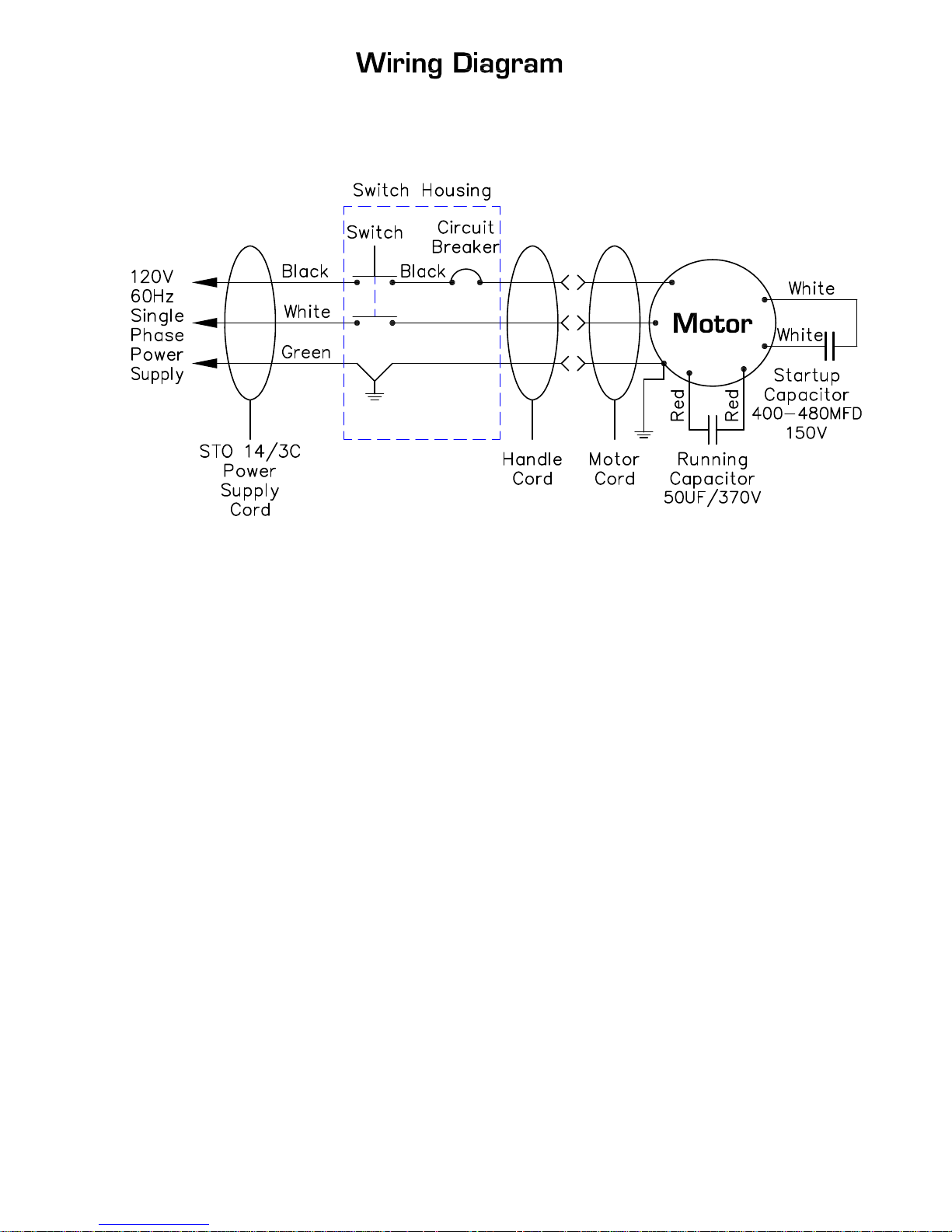
Wiring Diagram
2
3
4
4
5
6-9
10
Page 3
SAFETY PRECAUTIONS
GROUNDING INSTRUCTIONS
General –This floor – finishing machine shall be
grounded while in use to protect the operator
from electric shock. The machine is provided
with athree –conductor cord and a three contact
grounding type attachment plug to fit the proper
grounding ty pe receptacle. The green [or green
and yellow] conductor in the cord is the
grounding wire. Never connect this wire to other
than the grounding pin of the attachment plug.
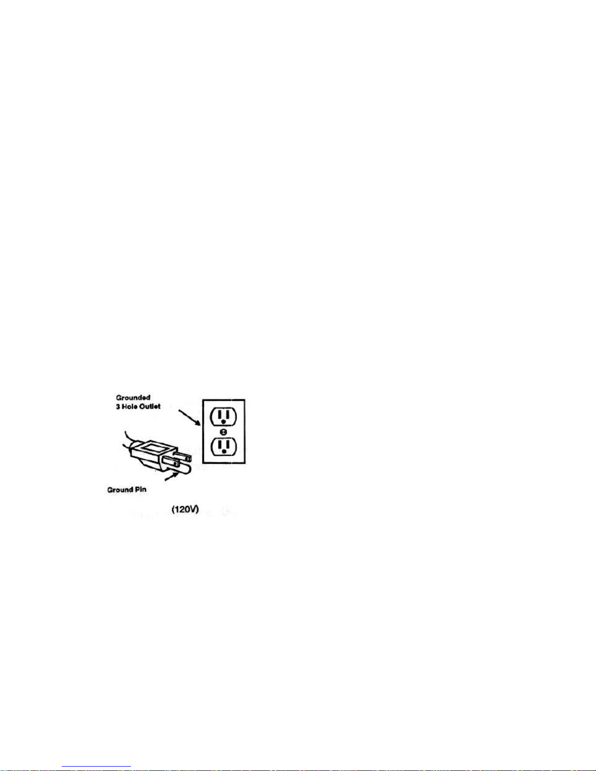
This machine is for use on a nominal 120-Volt
circuit and has a grounding plug that resembles
the plug illustrated in figure below. Make sure
that the machine is connected to an outlet
having the same configuration as the plug. No
adapter should be used with this machine.
This machine is intended for Commercial use. It
is constructed for use in an indoor environment
and is not intended for any other use. Use only
recommended accessories.
All operators shall read, understand and
exercise the following safety precautions:
1] Do not operate machine:
- Unless trained and authorized.
- Unless you have read and understand
operators manual.
- In flammable or explosive areas.
- With a damaged cord or plug.
- If not in proper operating condition.
- In outdoor areas.
- In standing water.
- With the use of extension cords.
2] Before operating machine:
- Make sure all safety devices are in place
and operate properly .
3] When using machine:
- Do not run machine over cord.
- Do not pull machine by cord or plug.
- Do not pull cord around sharp edges of
corners.
- Do not unplug by pulling onthe cord.
- Do not stretch cord.
- Do not handle plug with wet hands.
- Keep cord away from heated surfaces.
- Report machine damage of faulty
operation immediately.
4] Before leaving or servicing machine:
- Turn off machine.
- Unplug cord from outlet.
5] When servicing machine:
- Unplug cord from outlet.
- Use manufacturer supplied or approved
replacements parts.
3
Page 4

Operation of Floor Machine
* Read operators manual thoroughly prior to
operating or servicing this machine.
GENERAL USE
1] Remove any obstructions or other
obstacles in the area which is to be cleaned.
2] Place the handle in the upright position and
tilt machine back until handle rests on the
floor.
Be sure the machineis not plugged
into an outlet.
3] Attach the pad driver or brush to the machine
by placing the clutch plate over the gearbox
hub and turning the driver / brush 1/4 turn.
4] Place machine back into its upright position.
5]Plug power cord into gr ounded outlet.
* Never us e an extens ion cor d in
conjunction with the standard p ower cord.
6] The handle height may be adjusted by
lifting up the compression handle which is
located on the right side of the handle
tube about 1 foot above floor level.
Release the compression handle and
adjust handle to safe operating height,
then push back down on the compression
handle to lock the handle in operating
position.
7] To start the machine, press the red safety
button on the top of the upper switch
housing, and then squeeze either of the
operating triggers. [the safety button must
be depressed prior to squeezing the
operating triggers].
8] When the machine is in operation, both
hands should be placed on the switch
housing [upper handle].
9] During operation, to make the machine go
right, gently raise the handle. To make the
machine to left, gently lower the handle.
10] To stop the machine at any time, simply
release the operatingtrigger [s] andthe machine
will stop automatically.
MAINTENANCE
To keep the machine performing well for many
years, please follow the following maintenance
procedures.
* Always confirm that the machine is
unplugged prior to performing any
maintenanceor repairs.
1] Unplug machine as soon as you are done
using it.
2] Tilt machine back and remove pad driver or
brush.
*Never store a low speed machine with the
paddriverorbrushmountedtothe
machine
3] Clean the outside of the machine with a mild
cleaner.
4] Check power cord for any damage. If
damage is detected, replace the cord
immediately.
5] Lubricate wheels with a water resistant
lubricant once a month.
6] Check machine for loose or missing nuts and
bolts, and replace as necessary .
7] If the machine is used in a dusty environment,
you may remove the motor cover and blow
the motor clean with compressed air. This
will ensure proper ventilation, and allow the
motor to run cooler.
STORAGE
1] Unplug machine from power source andwrap
cord on handle.
2] Tilt machine back and remove pad driver or
brush.
3] Store machine in upright position and in a dry
area.
4
Page 5
5
Page 6
6
Page 7

DIA
NO
PART
NUMBER
DESCRIPTOIN
NO
REQ'D
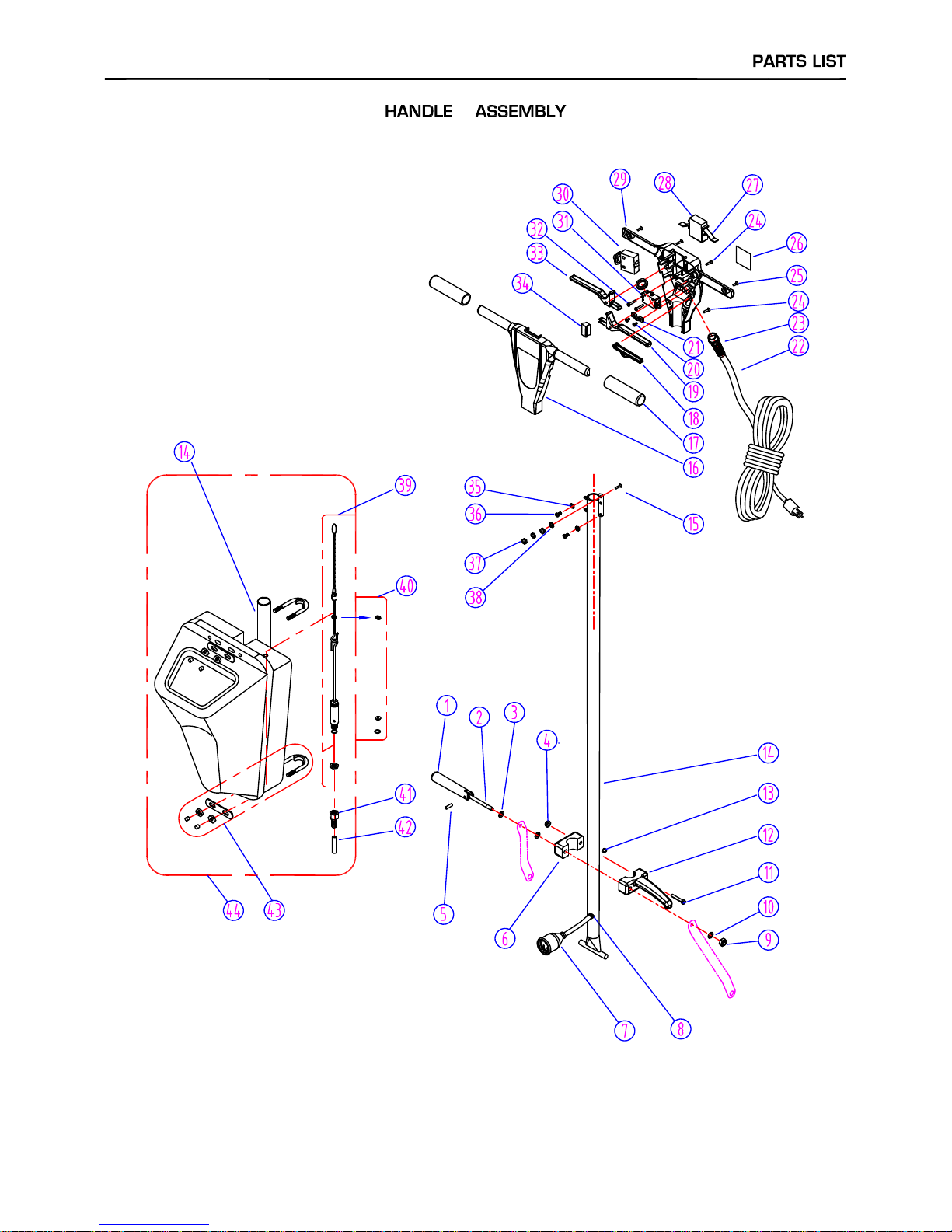
1 VF30016 HANDLE RELEASE 1
2 VF30015 BOLT HANDLE RELEASE 1
3 VF30018 WASHER,PLAIN 2
4 VF13503 NUT, LOCK,M8X5.7 1
5 VF30017 SCREW 1
6 VF30014 COVER,HOOK 1
VF45125 CORD,HANDLE 1
AS41901 PLUG PROTECTOR,SMALL MALE 1
8 VF50120 GROMMET 1
9 VF13504 NUT,LOCK,M10 1
10 VF13517 WASHER,PLAIN 1
11 VF14114 SCREW,M8X55 1
12 VF30013 HOOK 1
13 VF13493 SCREW,M6X10 1
14 AS312206 TUBE 1
15 AS22002 SCREW,M5X16 1
16 AS312208 FRONT COVER 1
17 VF48310 HANDLE GRIP 2
18 AS22006S LEVER,SOLUTION 1
19 AS22004S LEVER,LEFT,SWITCH 1
20 VV13661 SCREW,M4X12 2
21 VF48309 CLAMP BLOCK 1
22 VF45119CP POWER SUPPLY CORD, BLACK 1
23 AS22009 STRAIN RELIEF,CORD 1
24 GT13009 SCREW,M5X30 5
25 GT13008 SCREW,M5X20 2
VF41194CP SERIAL TAG FOR CPL17FB 1
VF41004CP SERIAL TAG FOR CPL20FB 1
27 GV40218 SPRING,SAFETY BUTTON 1
28 GV40209 SAFETY BOTTON 1
29 AS312209 REAR COVER 1
30 VF99010C BREAKER, CIRCUIT, 17A / A-0701HS 1
31 VF99023 SWITCH ASSY 1
32 VF14212 SCREW,M3X25 2
33 AS22005S LEVER,RIGHT,SWITCH 1
34 AS312203 COVER 1
35 VF13604 TEETH WASHER,¢54
36 VF14222 SCREW,M5X12 4
37 VV13633 NUT,M5 2
38 AS22003 TEETH WASHER,¢52
39 VF40200 VALVE ASSY KIT 1
40 VF40001 TANK SEAL KIT 1
41 VF40132 BARB HOSE 1
42 VF40139 HOSE,SOLUTION 1
43 VF40000 TANK MOUNTING KIT 1
44 MF-VF001 SOLUTION TANK 1
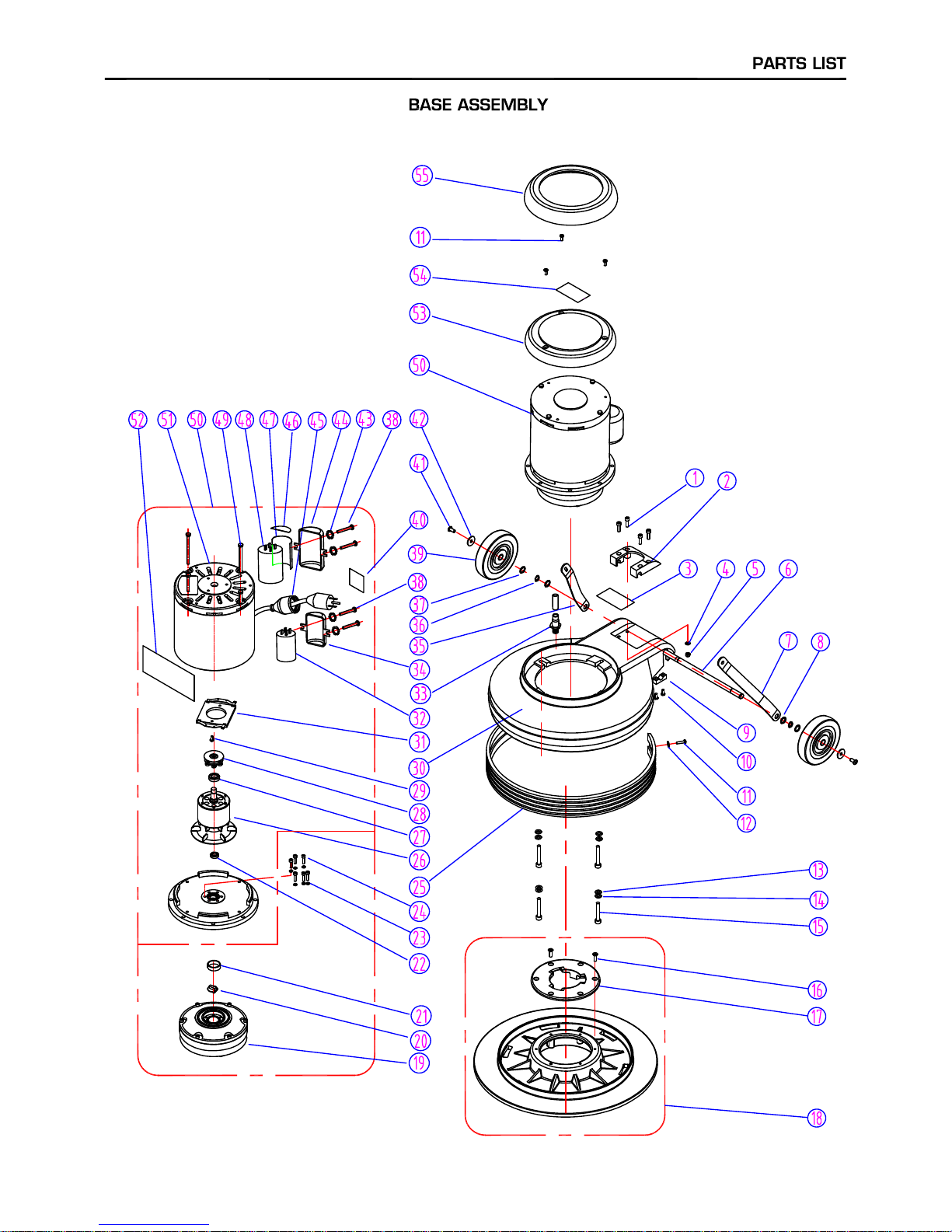
HANDLE GROUP
7
26
7
Page 8
8
Page 9
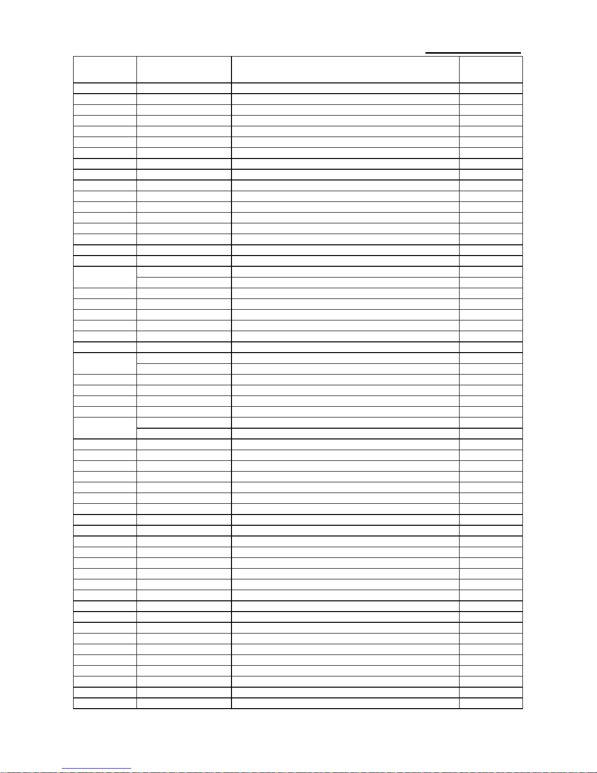
DIA
NO
PART
NUMBER
DESCRIPTION
NO
REQ'D
1
GT13080 SCREW, M6 X 30
4
2
A
S312201TP PLATE,HANDLE GUIDE
1
3
V
F41282 PARTS & SERVICE DECA
L
1
4
GT13030
W
ASHER, PLAIN, M6
4
5
V
F13502 NUT, LOCK, M6
4
6
V
F30026
A
XLE
1
7
V
F30020 BRACKET, LEFT HANDLE
1
8
V
V20274
W
ASHER, PLAIN, M13
4
9
GV40235 CLAMP BLOCK, AXLE
2
10
V
V13621 SCREW, SELF-TAPPING, ST, M5 X 20
4
11
V
A13474 SCREW, M5 X 16
5
12
V
F13474
A
W
ASHER, PLAIN, M5
4
13
V
F13524
W
ASHER, PLAIN, M8
4
14
V
F13519
W
ASHER, LOCK, M8
4
15
GT13016 SCREW, M8 X 55
4
16
MF-VF002-4
A
SCREW, SELF-TAPPING, 1/4"-1"
6
17 MF-VF002-2 CLUTCH PLATE
1
MF-VF021 PAD HOLDER, 16"
1
MF-VF022 PAD HOLDER, 19"
1
19
V
F999802B GEAR BOX
1
20
V
F99021 COUPLER
1
21
MT01102 SLEEVE
1
22
V
F999821 BEARING,6002 LLU
1
23
V
V13601
W
ASHER, LOCK, M5
6
24
V
V13636 SCREW, M5 X 30
6
A
S312101 BUMPER, 17"
1
A
S312204 BUMPER, 20"
1
26
Y
LQ19200B ROTOR WITH FAN ASSY
1
27
Y
CQ10501 BEARING ,6203 RZ
1
28
Y
CQ12301 CENTRIFUGAL SWITCH
1
29
V
V20509 SCREW, M5 X 10
2
V
F40101CP FRAME,17"
1
V
F40100CP FRAME,20"
1
31
Y
CQ12302 STATIONARY SWITCH
1
32
V
F999854 RUN CAPACITOR, 50uF / 370V
1
33
V
F40152 HOSE BARB
1
34
Y
LQ14601 MOUNTING FRAME (SMALL), CAPACITOR
1
35
V
F30019 BRACKET, HANDLE, RIGHT
1
36
V
F13520
W
ASHER, LOC
K
2
37
V
F50119
W
ASHER, PLAIN, M12
2
38
V
F14214 SCREW, M5 X 8
4
39
V
F48202
W
HEEL, 5"
2
40
V
F40994 LABEL, READ MANUA
L
1
41
V
F44012 SCREW, M6 X 12.7
2
42
V
F13666
W
ASHER, M6
2
43
V
F13604
W
ASHER, LOCK, EXTERNAL TOOTH
4
44
Y
CQ10615 MOUNTING FRAME (BIG), CAPACITOR
1
45
A
S41902 PLUG PROTECTOR, LARGE FEMALE
1
46
Y
CQ10414 CLEAR COVER
4
47
Y
CQ10416 CAPACITOR WARP
2
48
V
F999805 START CAPACITOR (BIG), 400-450UF/150V
1
49
Y
LQ17507 BOLT ASSEMBLY
4
50
V
F999792 MOTOR ASSEMBLY
1
51
V
F999787 MOTOR, 110V, 1.5HP
1
52
V
F44003 LABEL, MOTOR
1
53
V
F44001TP TOP COVER, MOTOR
1
54
V
F41281 LOGO, CLEANFREA
K
55
V
F47023 BUMPER
1
BASE ASSEMBLY
18
25
30
9
Page 10
10
 Loading...