

Page 1
DEHUMIDIFIER
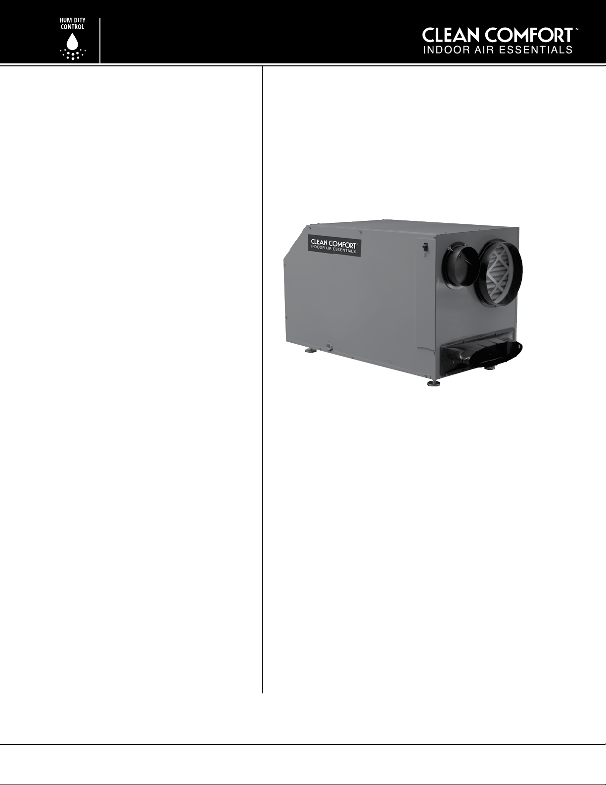
The Clean Comfort™ DV155 dehumidier
performs mulple funcons in a compact
enclosure: high-capacity dehumidicaon,
fresh air venlaon, and parculate ltraon.
Dehumidication
The highly ecient DV155 dehumidier ulizes
refrigeraon to cool the incoming air stream
below its dew point. This cooled and drier air
is used to pre-cool the incoming air stream
resulng in increased overall eciency. Aer the
pre-cooling stage the processed air is reheated
by passing through the condenser coil.
Fresh Air Ventilation (optional)
Fresh outdoor air may be ducted to the
dehumidier. This provides fresh air to dilute
indoor pollutants and replenish oxygen
content in the building. The amount of fresh
air venlaon can be regulated by a variety
of dampers and controls in order to provide
desired venlaon rates.
DV155 VENTILATING
DEHUMIDIFIER
Installaon and Operaon Manual
Air Filtration
The DV155 features air ltraon, using a
MERV-11 media lter, to improve indoor
air quality.
Clean Comfort DV155
i
IMPORTANT: READ AND SAVE THESE INSTRUCTIONS. THIS GUIDE TO BE LEFT WITH EQUIPMENT OWNER.
IO-DV155
WWW.CLEANCOMFORT.COM
2/14
Page 2

TABLE OF CONTENTS
SAFETY PRECAUTIONS .................................... 3
INTENDED APPLICATION ................................ 3
REGISTRATIONS............................................... 3
OPTIONAL PARTS LIST .................................... 3
SPECIFICATIONS ............................................. 3
INSTALLATION ............................................... 4
Installaon Consideraons ......................................... 4
Locaon .................................................................... 4
Power Accessibility ................................................... 4
Space ........................................................................ 4
Low Voltage Wiring .................................................. 4
Backdra Damper ..................................................... 4
Support Structure and Suspension ........................... 4
Electrical Requirements ............................................ 4
Condensate (Water) Removal ................................... 5
Condensate Pump Installaon (Oponal) ................ 5
Installing Filter Door ................................................... 6
DUCTING .......................................................... 6
Installing Duct Collars ................................................. 6
Ducng for Dehumidicaon ..................................... 6
Fresh Air/Supply Air .................................................... 6
Ducng for Fresh Air (Oponal) .................................. 7
Fresh Air Venlaon ................................................... 7
Installaon in a Basement or Crawlspace
with an Exisng Forced Air HVAC System .................. 7
Installaon in an Ac with an
Exisng Forced Air HVAC System ................................ 8
Installaon in a Home with Two
Forced Air HVAC Systems ............................................ 8
Installaon in a Home with No Exisng
Forced Air HVAC System ............................................. 9
Ducng for High Eciency Filtraon .......................... 9
Quiet Installaon ........................................................ 9
CONTROLS ...................................................... 9
Digital Dehumidier and Venlaon Control ........... 11
MAINTENANCE .............................................. 11
High Eciency Air Filter ........................................... 11
Impeller Fan Oiling .................................................... 12
Oponal Fresh Air Intake ......................................... 12
Warranty .................................................................. 12
SERVICE ......................................................... 12
SERVICE PARTS LIST ...................................... 12
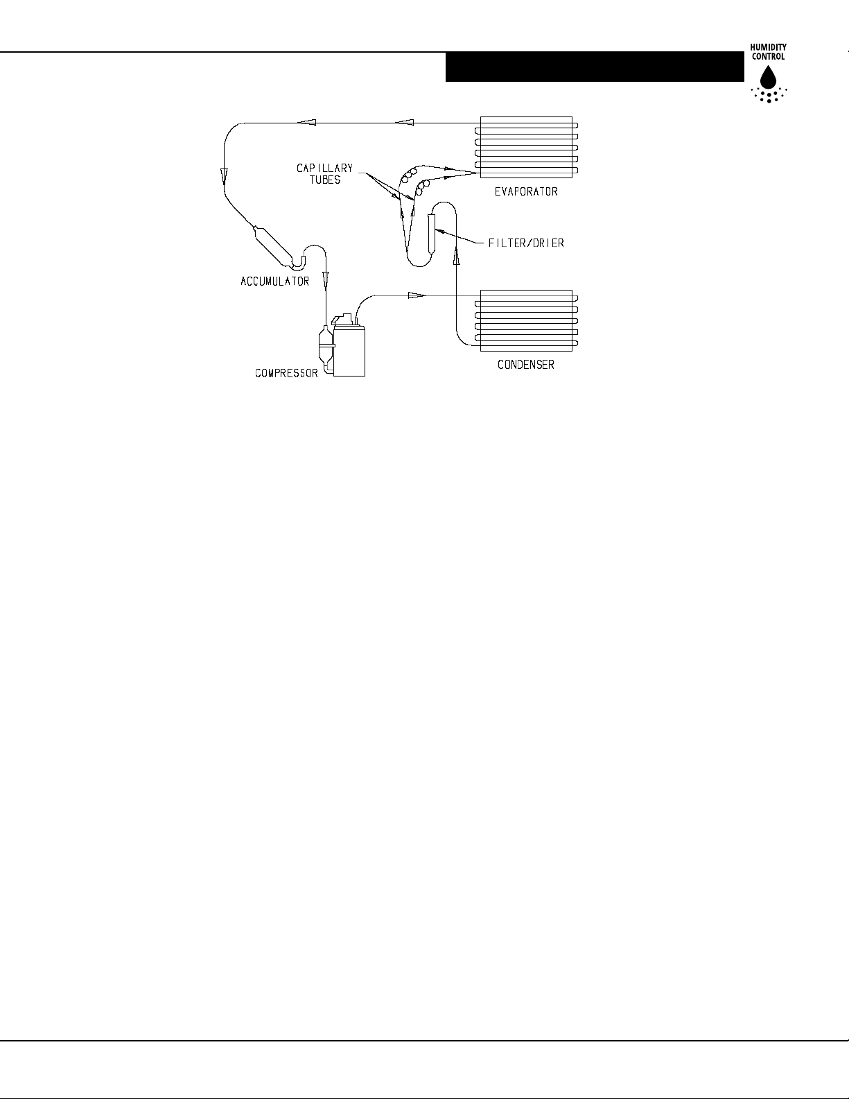
Technical Descripon of Dehumidier Operaon .... 12
TROUBLESHOOTING ..................................... 12
Refrigerant Charging ................................................ 14
Impeller Fan Replacement ........................................ 14
Compressor/Capacitor Replacement ........................ 14
Checking Compressor Motor Circuits ....................... 14
Remote Controls ....................................................... 15
Humidity Control ...................................................... 15
Programmable Venlaon Timer ............................. 15
Motorized Venlaon Damper ................................. 15
WIRING SCHEMATIC ...................................... 16
CONDENSATE PUMP INSTALLATION........... 17
WARRANTY .................................................... 18
Proprietary Notice
This document and the informaon disclosed herein are
proprietary data of Daikin North America LLC. Neither
this document nor the informaon contained herein shall
be reproduced, used, or disclosed to others without the
wrien authorizaon of Daikin North America LLC except
to the extent required for installaon or maintenance of
recipient’s equipment.
Liability Notice
Daikin North America LLC does not accept any liability
for damage due to installaons of dehumidicaon
equipment installed by unqualied personnel or the
use of parts/components/equipment that are not
authorized or approved by Daikin.
Copyright Notice
Copyright 2014, Daikin North America LLC
All rights reserved.
2
*INSTALLATION DATE (MM/DD/YYYY) ( / / )
__________________________________________________________
MODEL#: _______________________________________________
SERIAL#: _______________________________________________
*Ask Dealer to provide this informaon.
Our connuing commitment to quality products may
mean a change in specicaons without noce.
© 2014 DAIKIN NORTH AMERICA LLC
Houston, Texas • USA
www.cleancomfort.com
1-855-239 -2665
WWW.CLEANCOMFORT.COM
IO-DV155 IO-DV155
Page 3
SPECIFICATIONS
Safety Precautions
Read the installaon, operaon and maintenance
instrucons carefully before installing and operang
this device. Proper adherence to these instrucons is
essenal to obtain maximum benet from your DV155
indoor air quality systems.
READ AND SAVE THESE INSTRUCTIONS
WARNING!
i
This symbol indicates important instrucons. Failure to
heed them can result in serious injury or death.
CAUTION!
i
This symbol indicates important instrucons. Failure to
heed them can result in injury or material property damage.
Intended Application for DV155
Dehumidier
For the ideal installaon, draw air from the central part
of the home and return it to isolated areas of the home
like the bedrooms, den, ulity room, or family room.
The ductwork of the exisng heang system can be
used to supply dehumidied air to the home.
Registrations
The Clean Comfort DV155 conforms to UL STD 474 and
CSA Standard C22.2 No.92.
Optional Parts List for DV155
Ventilating Dehumidier
Part No. Description
DVP-4034748
DVP-4034753 Digital Control with remote
DVP-4034735 16"x20"x2" MERV 11
lter for DV155 dehumidier
DVP-4034737
DV090 and DV155 dehumidiers
DVP-4034744 10" Oval to Round Adapter
for DV155 dehumidier
DVP-4034742 10" Backdra Gravity Damper for DV090
and DV155 dehumidiers
Digital Control
6" Duct Damper, Motorized for DV070,
Specications
Part Number: DV155
Blower: 391 CFM @ 0.0" WG
363 CFM @ 0.2" WG
337 CFM @ 0.4" WG
Power: 920 Was @ 80°F/60% RH
Supply Voltage: 110-120 Volt - 1 Phase - 60 Hz
Current Draw: 8.0 Amps
Energy Factor: 3.5 L/kWhr
Operating Temp.: 56 °F (13 °C) Min, 95°F (35 °C) Max
Sized For: Up to 3500 Sq. Ft. - Typical
Performance at 80° F/60% RH:
Capacity: 155 Pints/Day (73 L/Day)
Eciency: 7.3 pints/kWhr (3.5 L/kWhr)
Duct Connections: 6" Round Inlet; 10” Round Inlet;
10" Oval Outlet
Air Filter:
Eciency: MERV-11
Dust Spot Test
Size: 16" x 20" x 2"
Power Cord: 10 . (3 m)
Drain Connection: 3/4" Threaded FNPT
Refrigerant Type: R410a (Refer to manufacturer's
label for more informaon)
Dimensions:
Width:
Height:
Depth:
Weight:
Standard 65% Ecient ASHRAE
Unit Shipping
20¼" (51.4 cm) 24" (61 cm)
21¾" (55.2 cm) 28¼" (71.8 cm)
38" (96.5 cm) 42" (107 cm)
140 lbs (64 kg) 160 lbs (73 kg)
WWW.CLEANCOMFORT.COM
3
Page 4

SPECIFICATIONS
Installation
CAUTION!
i
Prior to installaon of the DV155, the following consider aons for selecng the locaon for this equipment should
be reviewed. The DV155 can be installed in a variety of
locaons to meet the owner’s needs, and integrate with
exisng forced air systems or exisng ductwork if desired.
The locaon choice is conngent on a variety of require ments not limited to: ease of service, controls access,
drainage, ltraon, access to power, fresh-air venlaon,
water damage prevenon and current regulatory codes
(ASHRAE, re, etc). Please address all of these issues
before you select the device’s locaon.
Installation Considerations
Location
• This equipment is designed to be installed INDOORS
IN A SPACE THAT IS PROTECTED FROM RAIN AND
FLOODING.
• Install the unit with enough space to access one of the
side panels for maintenance and service.
• Avoid direcng the discharge air at people, or over the
water in pool areas.
• If used near a pool or spa; be certain there is NO
chance the unit could fall into the water, splashed and
that it is plugged into a GFCI (GROUND FAULT CIRCUIT
INTERRUPT) OUTLET.
• DO NOT use the unit as a bench or table.
• DO NOT place the device directly on structural members. Provide vibraon isolaon in order to minimize
operaonal vibraon and/or noise.
• A drain pan MUST be placed under the unit if installed
above a living area or above an area where water leakage could cause damage.
• Locate the unit near the exisng HVAC system to minimize the required ductwork for connecng it to the
exisng air handling system. The controls for the dehumidier are remote from the unit and must be located
in the space that is to be condioned. The controls are
low voltage (24 VAC) and should be connected to the
unit with low voltage thermostat cable.
• If fresh air venlaon is desired, thought should be given to the locaon for the fresh air ducng. A 6” round
insulated duct will have to be installed on the unit and
run to the outside of the home to bring in fresh air. Use
an 8” insulated round duct for lengths of more than 50
feet or if more than 100 CFM is needed. Consult local
codes for necessary distances from exhaust ports when
installing fresh air return.
Power Accessibility
Unit should be located in an area where the cord’s length
(10') can easily reach a 115VAC electrical outlet with a
minimum of a 15 A circuit capacity.
Space
Locaon should have enough clearance to handle the
unit’s overall dimensions as well as the necessary
return/supply ductwork to the unit. Allow a minimum
21" clearance to the side of the unit to allow for lter
removal and replacement.
Low Voltage Wiring
Unit locaon should be in an area where eld wiring the
remote controls (low voltage) to the unit will be possible.
Backdraft Damper
It is recommended that a backdra damper be used
in the supply duct of the DV155, especially when
connecng to the supply ducng system. The backdra
damper prevents supply air from counter owing through
the DV155 when it is not operang. The unit locaon
should be chosen to allow installaon of this accessory if
requested by the end user.
Support Structure and Suspension
Place the DV155 on supports to raise the base of the unit
2.5" above the drain pan beneath it. Do not place the
DV155 directly on structural building members without
vibraon absorbers or unwanted noise may result.
The DV155 may be suspended with steel hanger straps
(plumbers tape) or a suitable alternave from structural
members, as long as the suspending assembly supports
the DV155’s base in its enrety. Do not hang the DV155
from its cabinet. Remember to place a drain pan under
the unit if it is suspended above a nished area or above
an area where water leakage could cause damage.
Electrical Requirements
i CAUTION!
Do not allow the yellow lead from DV155 to contact
the red lead OR white lead from the DV155 or the
transformer will be destroyed.
The Clean Comfort DV155 dehumidier plugs into a
common grounded 115VAC outlet. The device draws
8.0 Amps under normal operang condions. If used
in a wet area (or a basement prone to ooding),
a ground fault circuit interrupter (GFCI) protected
circuit is required. Please, consult local electrical codes
for any further informaon.
4
WWW.CLEANCOMFORT.COM
IO-DV155 IO-DV155
Page 5
INSTALLATION CONSIDERATIONS
The DV155 can be controlled by a variety of devices
including the Clean Comfort DVP-4034748 or
DVP-4034753 digital controls. The controls are to be
located remotely from the unit and located in the
space to be condioned. The controls are low voltage
(24 VAC) and should be connected to the DV155 with
low voltage wire (thermostat or other appropriate).
Install the digital control in a central area of the home
where it will sense the relave humidity accurately.
i CAUTION!
Do not install the control where it may not accurately
sense the relave humidity such as near HVAC supply
registers, exterior doors, windows, water sources,
or on an outside wall.
The installer must supply the wiring between the
DV155 and the control. Be sure to safely route the
control wiring to prevent damage during installaon.
i CAUTION!
Do not cross wires when connecng the DV155 and
the control or damage to the transformer may result.
The remote controls of the DV155 are powered by a
low voltage circuit (24VAC) and must NEVER contact
or be connected to a high voltage circuit.
The control wires leaving the DV155 and the control are
numbered and color-coded to prevent confusion. Some
of the controls wires leaving the DV155 may not be used
with certain controls and should be le unconnected with
wire nuts taped onto the stripped ends for safety. Be sure
to consult the electrical schemac in this manual or inside
the access panel of the DV155 before making control
connecons.
Condensate (Water) Removal
The Clean Comfort DV155 dehumidier generates
condensate. Condensate drains by gravity via the drain
port. Install a 3/4" male NPT adapter to the drain pan.
It is necessary to assemble your own drain pipe assembly
ulizing 3/4" PVC pipe to route the condensate to a drain.
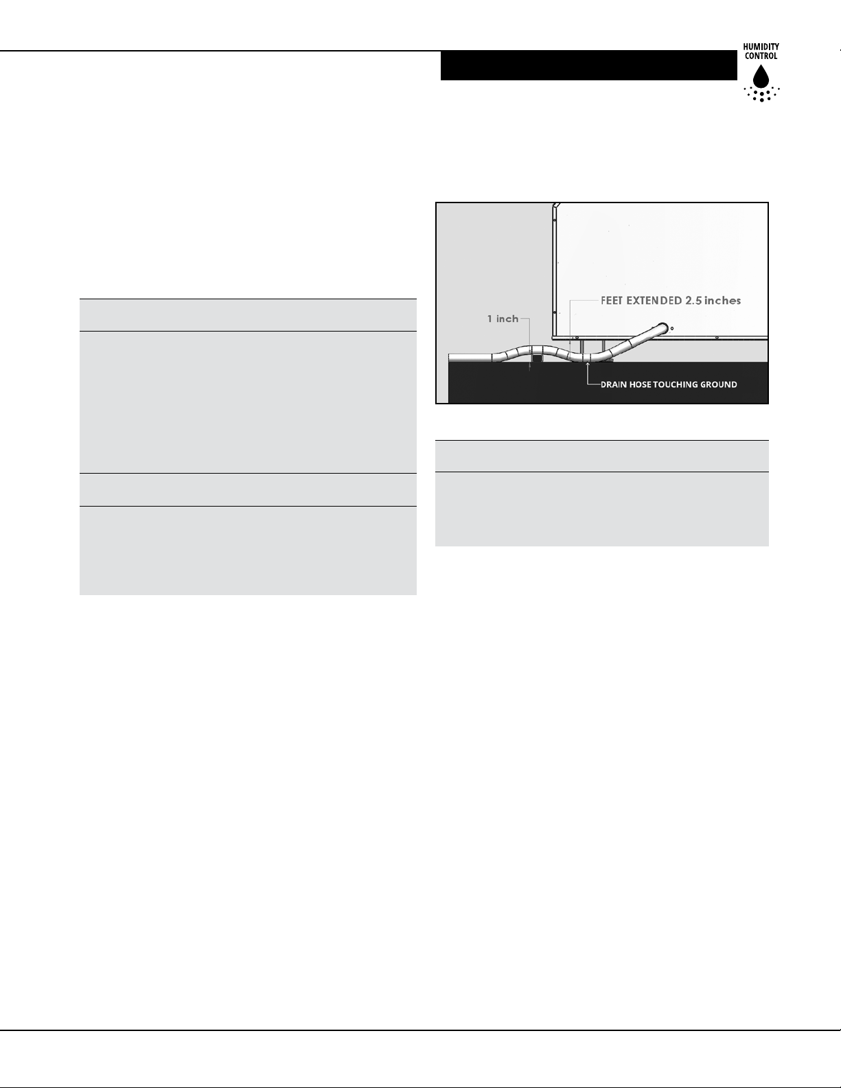
Pitch/grade of drain should be 1" per 10'.
Take care when installing the drain pipe to drain port
of the DV155; Use an adjustable wrench to secure the
drain port.
When installing the drain hose make sure the feet are
extended such that the dehumidier is 2 1/2" o the
ground. Then coil the drain hose under itself or posion
a spacer to li the hose 1" o the ground aer the hose
has touched the ground. This procedure will create
a trap that ensures your unit drains correctly.
See Figure 1 for further visual claricaon.
Figure 1: Trapping of condensate drain line
i CAUTION!
A trap in the line is required for the unit to drain properly.
Local codes may require a trap. Use care to keep the pipe
assembly as at to the oor as possible. Kinks and/or
humps will prevent proper drainage.
Lifting Condensate
An oponal condensate pump may be installed if a vercal
li is required to dispose of the condensate. The condensate pump can be ordered direct from your dealer.
Condensate Pump Installation (Optional)
A condensate pump can be installed on the condensate
drain line of the Clean Comfort DV155 dehumidier if
vercal li is required to dispose of the condensate.
Condensate is automacally pumped to a remote locaon
when the water level in the condensate pump's reservoir
rises to close the automac oat switch. In the event
the pump fails and water rises too high in the reservoir a
Safety Float Switch will become open. The leads from this
switch should be installed in series with the yellow or blue
eld wires to prevent the pump from overowing. If the
yellow wire is in series with the Safety Float Switch the
DV155 and the dehumidier will shut o. If the blue wire
is in series with the Safety Float Switch the compressor
will turn o but the DV155 will connue to venlate or
circulate air as normal. Contact your local electrician to
install the Safety Float Switch directly to the dehumidier.
For installaon guidelines, refer to the "Condensate Pump
Installaon" secon at the back of this manual.
WWW.CLEANCOMFORT.COM
5
Page 6
DUCTING
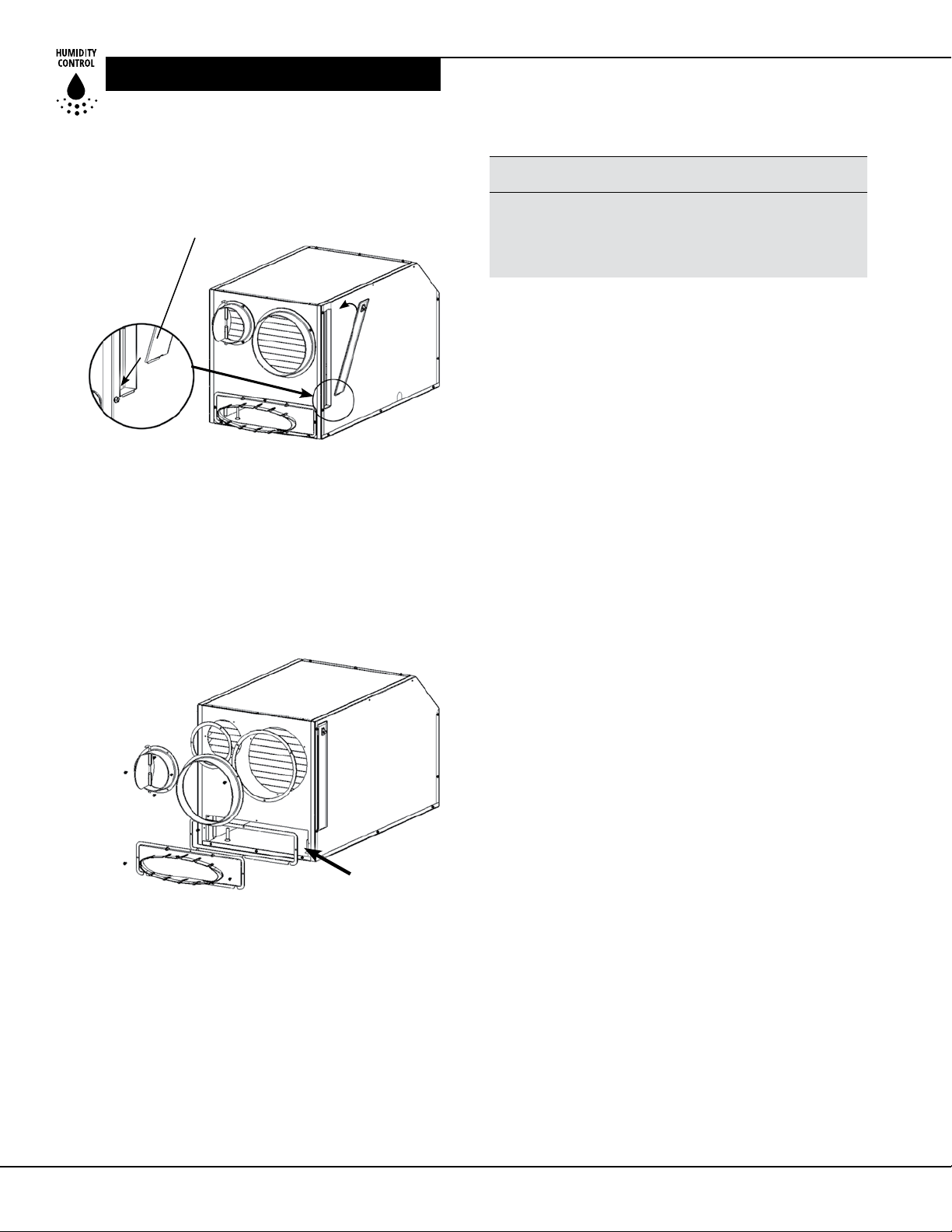
Installing Filter Door
Insert tab on the boom of the door, in between the
foam installaon and the metal side.
Push down on the plasc door latch and swing door
shut. Once the door is shut release the door latch.
Ducting
Installing Duct Collars
The DV155 is equipped with 10" and 6" round inlet collars
and a 10" oval exhaust collar.
Remove the 2 round ducts, oval duct seal and small bag of
mounng hardware from inside the rectangle opening.
Adhere seal to the back of oval duct and mount the ducts
to the front of the dehumidier using screws provided.
Fresh Air/Supply Air
i CAUTION!
DO NOT draw air directly from the kitchen, laundry, or
isolated basement. You may draw air from a basement
that is open to the home. All exible ducng connected
to the DV155 should be UL listed.
The inlet of the DV155 is the 10" diameter hole at the
lter enclosure end of the unit. A 10" round collar is
supplied with the unit to aach to round duct. The duct
may be permanently aached to the collar. A 6" round
collar is provided with the unit to aach to the 6" hole at
the lter enclosure end of the unit. The 6" collar should
be capped if venlaon with make-up air is not desired.
If venlaon is desired, see secon tled “Ducng for
Fresh Air (Oponal)”. A 10" oval collar is supplied with the
unit for the outlet of the DV155.
A short piece of exible ducng on ALL DV155 duct
connecons is recommended to reduce noise and
vibraon transmied to rigid ductwork in the home.
Ducng the DV155 requires consideraon of the
following points:
Duct Sizing: For total duct lengths up to 25', use a
minimum 10" diameter round or equivalent rectangular
duct. For longer lengths, use a minimum 12" diameter
or equivalent duct. Grilles or diusers on the duct ends
must not excessively restrict airow.
Collars and hardware
are located here.
Ducting for Dehumidication
For the ideal installaon, draw air from the central part
of the home and return it to the isolated areas of the home
like the bedrooms, den, ulity room, or family room. Be sure
to ulize as many of these remote rooms as possible and not
just one locaon. The ductwork of the exisng HVAC system
can be used to supply air to the home. If the exisng supply
goes to isolated areas of the home, discharge the supply
from the DV155 into the supply duct of the exisng HVAC
system. If the exisng heang system incorporates a central
supply, installaon of a separate supply duct from the DV155
to each isolated area is recommended.
6
Isolated Areas: Eecve dehumidicaon may require
that ducng be branched to isolated, stagnant air ow
areas. Use 8" or larger diameter branch ducng to each
of two or three areas, use 6" or larger to each of four or
more areas. Provisions must be made to provide airow
from supply locaons to central return locaon. Proper
air distribuon is important to ensure even humidity
control and heat distribuon throughout the home.
Connecng to exisng HVAC systems: An oponal 10"
gravity backdra damper is available to prevent reverse
air ow through the DV155. If the DV155 is ducted to the
supply of an air handler, the backdra damper should be
placed in the DV155 supply duct. Venlaon operaon is
controlled by the digital control oered with the DV155.
These controls determine the me/frequency that the
unit introduces outside air into the HVAC system.
The amount of outside air can be restricted by the blade
damper in the 6" collar. Some control opons require a
6" motorized damper be installed in the 6" fresh air duct.
WWW.CLEANCOMFORT.COM
IO-DV155 IO-DV155
Page 7

DUCTING
i CAUTION!
Do not connect with a stac pressure greater than
or equal to +.5 WG. Contact Technical Support at
1-855-239-2665 for addional details.
Ducting for Fresh Air (Optional)
Fresh air may be brought into the home by connecng
an insulated duct from outside the home to the 6" inlet
of the DV155 and turning on the fan switch or acvang
the humidity control. Acvate the venlaon mer
on units with the venlang and humidity control
DVP-4034748 to bring in fresh air. Refer to the Controls
secon of this manual for programming instrucons of
the venlaon mer.
Advantages of this form of venlaon include:
1. Outside air is ltered before entering the building.
2. Outside air will be dehumidied before entering if
the DV155 is running in dehumidicaon mode.
3. Drawing air from outside and blowing inside aids in
slightly pressurizing the home. This helps prevent
dirty and humid air from entering the home elsewhere. It also reduces the potenal for carcinogenic
radon gas to enter and provides a small amount of
make-up air for atmospheric combuson and exhaust
devices such as a clothes dryer, replace, furnace or
water heater.
4. Exhaust fans are recommended in the bath rooms
and kitchen.
In cold climates or areas where the outdoor dew point is
low at mes, venlaon can be used to dehumidify the
home, making the DV155 capable of year-round drying.
This is accomplished by bringing the dry, low dew point
air into the home during these mes. This approach is
oen more economical than running the dehumidier
to remove excess moisture from the home.
In cold climates, it is crical to adequately venlate to
reduce the indoor humidity to avoid moisture accumulang in the wall cavies. For example; in a house that
experiences condensaon on the interior surface of the
windows during the winter, increasing the amount of
venlaon will oen cure the problem.
An insulated 6" diameter duct is generally sucient to
provide up to 100 CFM of outside air. Large quanes
of outside air can impact the DV155´s performance
posively or negavely, depending upon the inside
and outside air condions.
The outside air duct should be connected to the
6" round collar on the front of the DV155. The amount
of outside air can be restricted by the blade damper
in the 6" collar.
Fresh Air Ventilation
Venlaon controls determine the me/frequency
that the DV155 introduces outside air into the home.
The amount/frequency of venlaon should be based
on the size and occupancy of the residence. If you are
unsure of your venlaon air requirements or have
need for higher air ows, consult Technical Support
by calling 1-855-239-2665.
Installation in a Basement or Crawlspace
with an Existing Forced Air HVAC System
It is recommended that a new, separate return duct
be installed for the DV155 from a central area
of the house.
If this is not possible, and if the exisng system has
mulple returns, select one to disconnect from the
exisng forced air system and use it for the dedicated
DV155 return. Always select a return from a central
locaon in the home in an area that is always open
to the rest of the home. Do not use a return from a
room that may have its door closed much of the me.
If the home in which the DV155 is to be installed has
an exisng forced air HVAC system, ulize the HVAC
system to make the DV155 installaon easier.
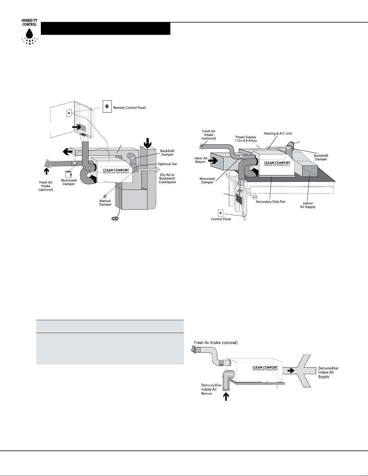
Basement Installation: Install a separate 10" return
to the DV155 in a central area of the home. Oponal:
Duct the supply from the DV155 to a 10" x 10" x 10"
tee/damper, adjusted to 20% open to the basement.
This allows the ability to discharge a variable amount
of dehumidied air into a basement that may not be
well served by the exisng duct system, especially
during the summer months. Duct the other side of
the tee to the air supply of the exisng HVAC system.
WWW.CLEANCOMFORT.COM
7
Page 8
DUCTING
r
A backdra damper is required in the duct between the
10" tee and the central supply duct to prevent air from
being discharged into the basement during central fan
operaon. Connect a duct from outside to the 6" collar
of the DV155 if you wish to provide venlaon air.
See Figure 2.
Indoor Air Return
to Dehumidifier
Supply from
dehumidifier
Figure 2: Basement or Crawlspace Installaon
The preferred method of installaon is to create a
separate return to the DV155 in a central area of the
home. Duct the supply from the DV155 to the air supply
of the exisng HVAC system. Connect an insulated duct
from outside to the 6" collar of the DV155 if you wish to
provide fresh make-up air. Adjust a damper in the duct
to provide the desired air ow. Using the digital control,
program the unit to bring in the desired amount of fresh
air. See Figure 3.
Supply from dehumidifie
Indoor Air Return
to Dehumidifier
Figure 3: Ac Installaon
Crawl Space Installation: Install a separate return to the
DV155 in a central area of the home. Oponal: Duct the
supply from the DV155 to a 10" x 10" x 10" tee/damper
that is 20% open to the crawlspace if desired. Duct the
other side of the tee to the air supply of the exisng HVAC
system with a backdra damper. Connect an Insulated
duct from outside to the 6" collar of the DV155 if you wish
to provide oponal venlaon. See Figure 2.
Installation in an Attic with an Existing
Forced Air HVAC System
i CAUTION!
ALWAYS install a catch pan with a drain or Safety Float
Switch for condensate under the DV155 in an ac
installaon or condensate may damage the living
space below.
The Safety Float Switch should be installed in series
with the eld wire that connects the blue (#5) lead from
the DV155 to the blue (#5) lead on the digital control.
If overow occurs, this Safety Float Switch opens the
compressor control circuit and stops water producon
before the catch pan overows. The DV155 will connue
to venlate or circulate air as normal, but will not
dehumidify unl this Safety Float Switch closes.
Installation in a Home with
Two Forced Air HVAC Systems
The DV155 can be installed into two typical HVAC
ducng systems. Install a separate return to the DV155
as directed above. Supply air from the dehumidier
should be split and routed to each dehumidier's supply
ducng system. A balancing damper and a backdra
damper are required in each duct between the DV155
and the HVAC ducng system. This allows airow to be
adjusted and prevents ow of air between the ducng
systems. Contact the factory for assistance, if necessary.
Figure 4: Installaon with No Exisng Forced
Air HVAC System
8
WWW.CLEANCOMFORT.COM
IO-DV155 IO-DV155
Page 9
CONTROLS
Installation in a Home with No Existing
Forced Air HVAC System
When installing the DV155 in a home that does not
have an exisng forced air HVAC system, a single return
to the DV155 should be installed in central open area
of the home.
DO NOT locate the return in a bathroom or a kitchen.
The supplies of the DV155 should be located in the
remote areas of the home such as bedrooms, den, etc.
Be sure to ulize as many of these remote rooms as
possible and not just one locaon. By ducng this way,
the air inside the enre home will circulate through the
DV155 to be ltered and dehumidied. Avoid discharging
all the air from the dehumidier to one locaon to
prevent heat buildup in that area. 4" diameter duct
is recommended for branches to the bedrooms,
6" diameter duct is recommended for branches to larger
areas. Connect an insulated duct from outside to the
6" collar of the DV155 if you wish to provide venlaon.
Ducting for High Eciency Filtration
The lter included with the DV155 is a high eciency
MERV 11 media lter. This lter should be checked every
three months and changed every 6-12 months.
Quiet Installation
Consider compression vibraon and airow noise during
installaon. Use of ex duct and/or vibraon isolaon
materials during mounng and ducng will result in
quieter operaon. A length of exible ducng on all DV155
duct connecons is recommended to reduce noise and
vibraon transmied to rigid ductwork in the home.
i CAUTION!
DO NOT allow the yellow lead from the unit to
contact the red lead or the white lead from the unit
or damage to the transformers will result.
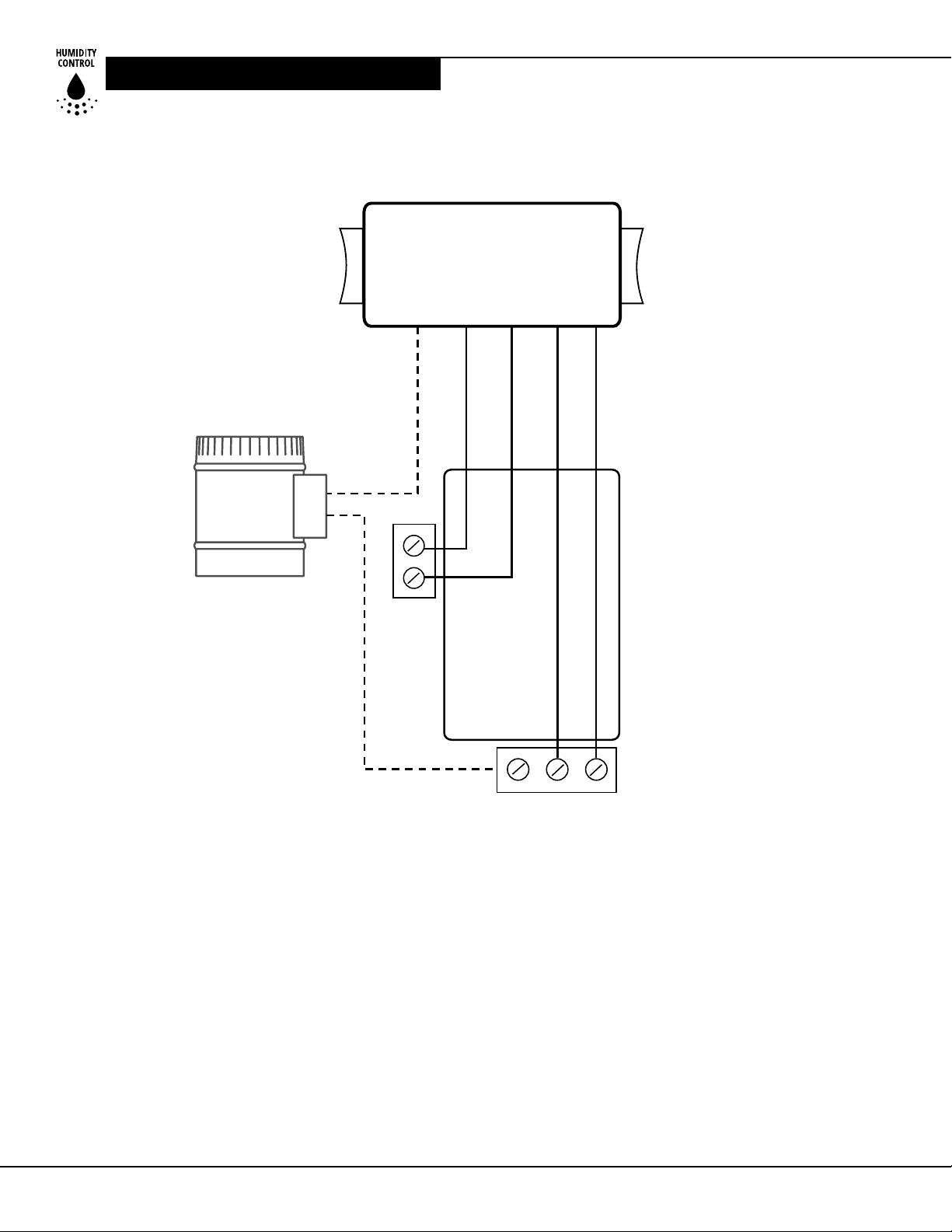
The DV155 dehumidier is controlled using ve,
color-coded wires:
Green (or brown) = Fan control
Blue = Dehumidicaon (fan and compressor) control
Red = 24VAC power transformer neutral side
(common with white)
White = 24VAC power transformer neutral side
(common with red)
Yellow = transformer high side
A 40VA transformer is wired between the red/white
lead and the yellow leads of the DV155. This low
voltage power source powers the relay coils which
control the fan and compressor.
This 24VAC transformer can also be used to power
HVAC accessories external to the dehumidier.
• To turn the dehumidier ON, make contact
between yellow and blue wires.
• To turn the fan ON, make contact between yellow
and green (or brown) wires.
• To power an HVAC accessory, connect the accessory to the white (or red) wire and the yellow wire.
Controls
The DV155 can be equipped with various accessories to
control its operaon. The Clean Comfort DVP-4034748
digital control is recommended. The DVP-4034748 allows
homeowners the ability to monitor and control relave
humidity levels in their home as well as provide proper
venlaon. This digital control is also oered with a
remote sensing opon (part number DVP-4034753) for
installaons where the preferred locaon for mounng
the digital control is not close to the area where humidity
control is needed.
WWW.CLEANCOMFORT.COM
i CAUTION!
If an oponal damper is not used, do not connect the
white wire to the DVP control or damage to
the transformer may result.
9
Page 10
CONTROLS
DMP COMP FAN
Wiring of Digital Control
OPTIONAL
DAMPER
Dehumidifier
WHITE
YELLOW
RED
BLUE
GREEN (or BROWN)
24 VAC
OR
DVP-4034748
Figure 5: Wiring of Digital Control for Clean Comfort
Venlang Dehumidier
DVP-4034753
10
WWW.CLEANCOMFORT.COM
IO-DV155 IO-DV155
Page 11
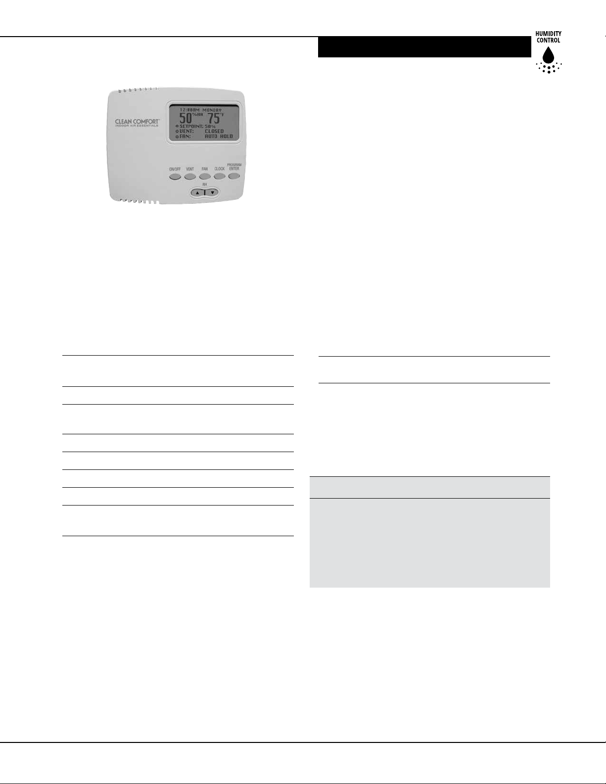
Figure 6: Digital Control for Clean Comfort Venlang
Dehumidier
Clean Comfort Dehumidier &
Ventilation System Control
When used with Clean Comfort Whole House Venlang
Dehumidiers, the DVP-4034748 and DVP-4034753
digital controls allow homeowners the ability to monitor
and control relave humidity levels in their home.
Digital control P/N: DVP-4034748
Digital control
(with remote) P/N: DVP-4034753
MAINTENANCE
Major Operations
• Digital control of Relave Humidity (Digital Set-Point)
• Fan/Filter Operaon
• Programmable Venlaon Timer
• Large, easy-to-read backlit LCD display
• Easy interacon with air handler fan
(Interlock/Lockout)
• High Temperature Cut-Out
• Dryout Cycle Timer
• Auto Reboot
• Remote Sensor (DVP-4034753 model ONLY)
For Technical Support, please call 1-855-239-2665.
Must be a licensed HVAC contractor or authorized
distributor to install this product.
Maintenance
For Homeowner - Routine Maintenance
Part No. Description
DVP-4034735 16"x20"x2" MERV 11 lter for
DV155 dehumidier
Operating Voltage: 24VAC
Max Current
DM P, COM P, FAN : 1 AMP each
Humidity Range/Accuracy: 10 – 95% RH, ± 5%
Humidity Range/Set Point: 35 – 70% RH
Auxillary Relay Capacity: 5 Amps, 24VAC
Temp Range/Accuracy: 30°-90°F (-1°-32°C), 2%
Size: 4.95"L x 1.06"W x 4.19"H
(12.6 cm L x 2.7 cm W x 10.6 cm H)
High Eciency Air Filter
The Clean Comfort Venlang Dehumidiers are
equipped with a MERV 11 media lter. This lter
should be checked every three months and changed
every 6-12 months. Operang the unit with a dirty
lter will reduce dehumidier capacity and eciency.
i CAUTION!
DO NOT operate the DV155 dehumidier without the
MERV 11 lter or with a lter of lower performance
rang than MERV 11. The heat exchange coils inside
the unit could become clogged and require disassembly
to clean. Non-compliance with lter maintenance
guidelines (provided above) invalidates the
product warranty.
To replace the lter, remove the lter door from the side
of the DV155 dehumidier by gently pulling it away from
the body of the unit.
Remove the lter by gently pulling straight out of the
unit. Insert new lter in the same manner, pushing it
gently straight into the unit. Replace the lter door.
WWW.CLEANCOMFORT.COM
11
Page 12

SERVICE/TROUBLESHOOTING
Impeller Fan Oiling
The impeller fan motor is factory lubricated for
many years of normal operaon, and no further
oiling is required.
Optional Fresh Air Intake
Check and clean the screen on the outdoor fresh air intake
port seasonally. The screen may become plugged during
seasons when there are many parcles in the outdoor air.
Warranty
A consumer warranty cercaon is included at the end
of the manual. Please read it before any repair is iniated.
If a warranty repair is required, call the installing contractor or the factory at 1-855-239-2665 for warranty claim
authorizaon and technical assistance.
Service
i WARNING!
Servicing the DV155 Dehumidier with its high pressure
refrigerant system and high voltage circuitry presents a
health hazard which could result in death, serious bodily
injury, and/or property damage. Call your HVAC
contractor for servicing or repair of this equipment.
Service Parts List: Clean Comfort
DV155 Ventilating Dehumidier
Part No. Description
DVP-4034804 Transformer, 120/24VAC, 40 VA
DVP-4034808 Fan Relay, SPDT, 24VAC, 15A
Technical Description of Dehumidier
Operation
The DV155 uses a refrigeraon system similar to an air
condioner’s to remove heat and moisture from incoming
air, and add heat to the supply air that is discharged from
the dehumidier. Hot, high-pressure refrigerant gas is
routed from the compressor to the condenser coil
(See Figure 7). The refrigerant is cooled and condensed
by giving up its heat to the supply air being discharged
from the unit. The refrigerant liquid then passes through
a strainer and capillary tubing which causes the refrigerant pressure and temperature to drop. It next enters the
evaporator coil where it absorbs heat from the incoming
air and evaporates. The evaporator operates in a ooded
condion, which means that all the evaporator tubes
contain liquid refrigerant during normal operaon.
A ooded evaporator should maintain nearly constant
pressure and temperature across the enre coil, from
inlet to outlet.
The mixture of gas and liquid refrigerant enters the
accumulator aer leaving the evaporator coil. The
accumulator prevents any liquid refrigerant from
reaching the compressor. The compressor evacuates
the cool refrigerant gas from the accumulator and
compresses it to a high pressure and temperature to
repeat the process.
Troubleshooting
Neither fan nor compressor running.
Dehumidication is being called for. No fan call.
1. Unit unplugged or no power to outlet.
2. Humidity control set too high.
3. Loose connecon in internal or control wiring.
4. Defecve Compressor relay.
5. Defecve control transformer.
Compressor is not running. Dehumidication is
being called for. No fan call.
1. Defecve compressor run capacitor.
2. Loose connecon in compressor circuit.
3. Defecve compressor overload.
4. Defecve compressor.
5. Defrost thermostat open.
6. Defecve compressor relay.
12
WWW.CLEANCOMFORT.COM
IO-DV155 IO-DV155
Page 13
TROUBLESHOOTING
Figure 7: Refrigeraon System of DV155 Dehumidier
Compressor cycles on and o. Dehumidication is
being called for. No fan call.
1. Low ambient temperature and/or humidity causing
unit to cycle through defrost mode.
2. Defecve compressor overload.
3. Defecve compressor.
4. Defrost thermostat defecve.
5. Dirty air lter(s) or air ow restricted.
6. Defecve fan relay.
Fan is not running. Dehumidication or fan is
being called for.
1. Loose connecon in fan circuit.
2. Obstrucon prevents fan impeller rotaon.
3. Defecve fan.
4. Defecve fan relay.
Low dehumidication capacity (evaporator is
frosted continuously). Dehumidication is
being called for.
1. Defrost thermostat loose or defecve.
2. Low refrigerant charge.
3. Dirty air lter(s) or air ow restricted.
4. Excessively restricve ducng connected to unit.
No ventilation. Ventilation is being called for.
1. Loose connecon in venlaon control circuit.
2. Loose connecon in damper power circuit.
3. Defecve fresh air damper.
Unit removes some water, but not as much
as expected.
1. Air temperature and/or humidity have dropped.
2. Humidity meter and or thermometer used are
out of calibraon.
3. Unit has entered defrost cycle.
4. Air lter dirty.
5. Defecve defrost thermostat.
6. Low refrigerant charge.
7. Air leak such as loose cover or ducng leaks.
8. Defecve compressor.
9. Restricve ducng.
10. Oponal Condensate Pump Safety Float
Switch open.
WWW.CLEANCOMFORT.COM
13
Page 14

REPAIRS
i WARNING!
ELECTRICAL SHOCK HAZARD: Electrical power must be
present to perform some tests. These tests should be
performed by a qualied service person.
Unit Test to Determine Problem
1. Detach eld control wiring connecons from
main unit.
2. Connect the yellow and brown pigtails from the main
unit together; only the fan should run. Disconnect the
wires.
3. Connect the yellow and blue pigtails from the main
unit together; the compressor and fan should run.
4. If these tests work, the main unit is working properly.
You should check the digital control and eld control
wiring for problems next.
5. Remove the digital control from the mounng box
and detach it from the eld installed control wiring.
Connect the blue, yellow, and green wires from the
digital control directly to the corresponding colored
pigtails on the main unit. Leave the violet, white and
red wires disconnected!
6. Engage the fan switch; the fan should run. Turn o the
fan switch.
7. Engage the dehumidistat funcon on the digital
control; the compressor and fan should run.
8. If these tests work, the problem is most likely in
the eld control wiring.
NOTE: Refrigeration systems should ONLY
be serviced by a qualied service technician.
If you need additional information, consult
Technical Support at 1-855-239-2665.
Refrigerant Charging
If the refrigerant charge is lost due to service or a leak, a
new charge must be accurately weighed in. If any of the old
charge is le in the system, it must be recovered before
weighing in the new charge. Refer to the unit nameplate
for the correct charge weight and refrigerant type.
Impeller Fan Replacement
The motorized impeller fan is a unitary assembly
consisng of the motor and impeller fan. If defecve,
the complete assembly must be replaced.
1. Unplug the power cord.
2. Remove the cabinet access panel.
3. Remove the screw aaching the impeller fan
support bracket to the base.
4. Disconnect the impeller fan leads inside the
electric box.
5. Remove fan/bracket assembly by removing 3
screws from the bracket and inlet ring assembly.
6. Remove the defecve impeller fan from the bracket
and replace with it with the new impeller fan.
7. Reassemble the new impeller fan by reversing the
above procedure. Note: There are two pins on the
backside of the cabinet that must align with the
two holes in the impeller fan support bracket.
Compressor/Capacitor Replacement
This compressor is equipped with a two terminal external
overload and a run capacitor, but no start capacitor
or relay.
Checking Compressor Motor Circuits
Perform the following tests if the impeller fan runs
but the compressor does not with the fan switch and
venlaon mer OFF and the humidity control ON.
1. Unplug the unit; remove the cabinet side and the
electrical connecon cover on the compressor top.
2. Plug in the unit and turn the humidity control to ON.
Check for 110 volts from compressor terminal R to
overload terminal 3 using an AC voltmeter. If voltage
is present, go to step 3. If no voltage, there may be
a loose connecon in the compressor circuit. Test
each component for connuity. See the appropriate
secon if a defect is suspected.
3. Unplug the unit, and then disconnect the red and
yellow wires from compressor terminals R & S.
Using an ohmmeter check connuity between the
points listed below.
4. Compressor terminals C and S: No connuity
indicates an open start winding. The compressor
must be replaced. Normal start winding resistance
is 3 to 7 ohms.
14
WWW.CLEANCOMFORT.COM
IO-DV155 IO-DV155
Page 15
OPERATION
5. Compressor terminals C and R: No connuity
indicates an open run winding. The compressor
must be replaced. Normal run winding resistance
is .5 to 2 ohms.
6. Compressor terminal C and overload terminal 1: No
connuity indicates a defecve overload lead.
7. Overload terminals 1 and 3: If there is no connuity,
the overload may be tripped. Wait 10 minutes and try
again. If there is sll no connuity, it is defecve and
must be replaced.
8. Compressor terminal C and compressor case: Connuity indicates a grounded motor. The compressor must
be replaced.
9. Disconnect the wires from the run capacitor. Set the
ohmmeter to the Rx1 scale. The capacitor is shorted
and must be replaced if connuity exists across its
terminals. If there is no needle movement with the
meter set on the Rx100000 scale, the capacitor is
open and must be replaced.
10. Reconnect the wires to the compressor and capacitor.
Plug in and turn on the unit. If the compressor fails to
start, replace the run capacitor.
Remote Controls
The DV155 dehumidier is controlled by digital controls
that are remote from the unit. You may or may not have
the devices listed below depending on the model of the
control you purchased. If the dehumidier fails to operate
as desired, always check the sengs of the controls to
insure that they are correct. Check that the controls are
receiving 24VAC from the dehumidier. Check the connecons between the dehumidier, the control, and the eld
control wiring.
Humidity Control
The humidity control is an adjustable switch that closes
when the relave humidity of the air in which it is located
rises to the screen set point. The DV155 dehumidier is
equipped with an automac defrost mechanism. If the
dehumidier operates in condions that develop frost on
the evaporator, it will sense the frost build-up and automacally defrost the evaporator. The dehumidier may
not appear to be operang correctly during the defrost
sequence, but once the defrost sequence is completed, the
unit will resume dehumidifying.
Programmable Ventilation Timer –
DVP-4034748 / DVP-4034753
The venlaon mer controls the impeller fan and the
motorized fresh air damper. When the venlaon mer
is acvated, the dehumidier will circulate the indoor
air, and bring in fresh air from outside. The venlaon
mer should be set for the required venlaon of the
residence. The home should be venlated with fresh air
as suggested by applicable codes and standards. If the
dehumidier fails to venlate as expected, check that the
me on the mer is correct. Also check the programs on
the mer to be sure that the mer is calling for venlaon at the correct mes.
Motorized Ventilation Damper
The motorized venlaon damper is controlled by
a eld-supplied venlaon mer, such as the Clean
Comfort DVP-4034748 control. The damper will open
when the venlaon mer is acvated to allow fresh
air into the home through the 6" diameter fresh air
inlet supply duct. The motorized venlaon damper
will remain closed when the venlaon mer is not
acvated to prevent over-venlang the home when
the unit is dehumidifying or recirculang the indoor air.
The motorized venlaon damper operates on 24VAC
from the control circuit.
i CAUTION!
DO NOT connect high voltage to the damper motor
or damage to the motor may result.
i CAUTION!
DO NOT force the blade of the damper by hand or
damage to the damper motor may result. The damper
opens in one direcon only. The damper rotates very
slowly; allow sucient me for the damper to cycle.
The damper opens in one direcon only. It rotates
very slowly; be sure to allow sucient me for the
damper to cycle. The damper will take approximately one
minute to cycle from closed to open or from
open to closed.
If the motorized venlaon damper fails to operate:
1. Check that the wiring is correct and that voltage is
present at the damper motor.
2. Check for any obstrucon inside the damper If the
motorized venlaon damper fails to operate aer
performing these checks, it must be replaced.
WWW.CLEANCOMFORT.COM
15
Page 16
WIRING SCHEMATIC
UNIT
N.O.
MAKE SURE WIRE IS
CAPPED IF DAMPER
IS NOT USED
GRN 5
WHT 4
RED 1
YEL 6
BLU 7
GRN 9
RED 6
GRN 5
WHT 4
RED 1
YEL 6
BLU 7
WHT 6
GRN 4
GRN 4
BLU 2
BLK 1
BRN 3
BLOWER CAPACITOR
BLK-3
COMPRESSOR
RELAY
6
4
VIO-8
BLK-2
1
BLOWER
RELAY
9
9
5
5
BLK-7
2
HUMIDITY
CONTROL
CUSTOMER SUPPLIED
CONTROL WIRING:
+24VAC
COM
5
BLU 2
LINE NEUTRAL
GRN-4
DEFROST
T-STAT
RUN
CAPACITOR
BA
BRN-3
BLK-1
115V/220V
24V
BLU
1
2
YEL
3
GRN
4
RED
24V
24Vac
60Hz
BLK-11
1Ph
BLK-10
BLK-1
YEL-6
WHT 6
5
COMCOM
115V 24V
WHT-6
COMPRESSOR
S
3
R
GRN-4
BLOWER
COM
XFMR
COM
BLU-7
1
GRN-5
3
E-BOX
7
3
2
CAPACITOR
YEL-5
RED-6
BLU-2
WHT-5
YEL-2
COMPRESSOR
RELAY COIL
0
1
14
13
BLOWER
RELAY COIL
BLK 1
2
RUN
PNK-3
4
5
9
14 13
WHT 4
2
AB
RED-1
WHT-4
1
2
3
8
16
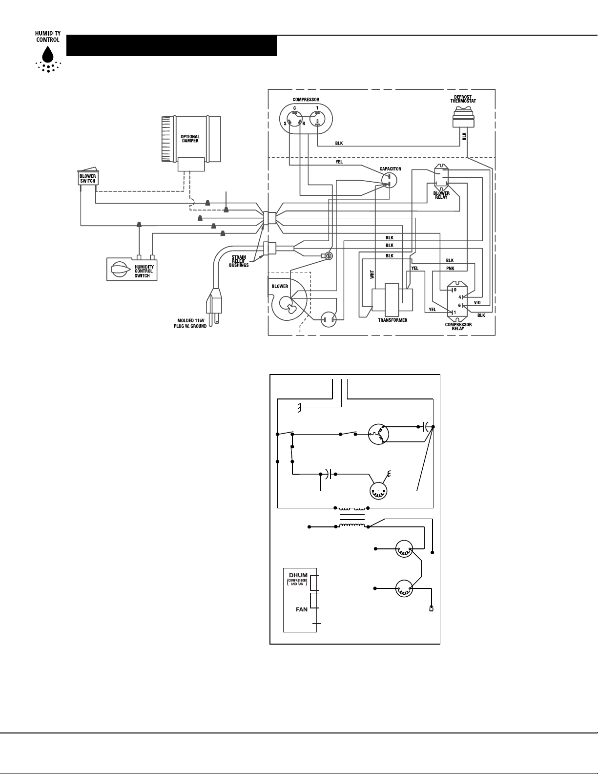
Figure 8: Wiring Schemac for DV155
WWW.CLEANCOMFORT.COM
IO-DV155 IO-DV155
Page 17
CONDENSATE PUMP INSTALLATION
CONDENSATE PUMP INSTALLATION
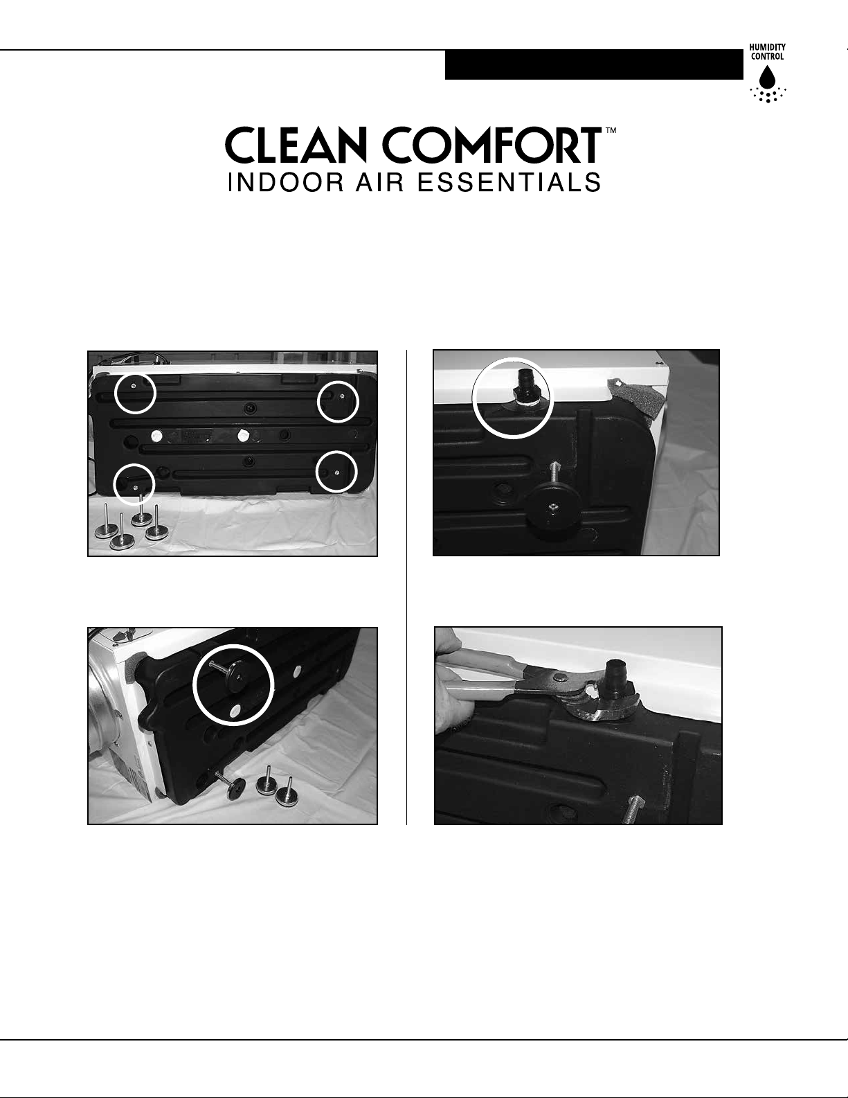
A condensate pump must be installed with leveling feet.
Do not use casters.
Depending on the specic model you have purchased,
the base of the humidier may look dierent than shown in the pictures below.
Step 1. Lay the DV155 unit on it's side. Make sure
the lter door is facing upward. Note the locaons
of the four leveling feet and the hose adaptor.
Step 3. Hand ghten the hose adaptor to get the
threads started. Turn clockwise.
Step 2. Parally screw in the leveling feet at the four
locaons.
Step 5. Install a suciently long drain hose to
connect the drain adaptor of the dehumidier
to the condensate pump reservoir using
eld-supplied ngs.
Step 6. Aach a drain hose to the condensate
pump and route it to a oor drain.
WWW.CLEANCOMFORT.COM
Step 4. Use adjustable pliers to nish ghtening.
Fully seat the drain adaptor so that no leaks occur.
Step 7. Use a level to ensure the dehumidier is
level before powering up the dehumidier and the
condensate pump.
Step 8. Plug in the condensate pump and the
assembly is completed.
Annual inspection of a properly
functioning pump is necessary.
17
Page 18

WARRANTY
Limited Warranty
Daikin North America LLC (“Daikin”) warrants as follows: the
Clean Comfort dehumidier (“Product”) will be free of material
defects in workmanship or materials for a period of ve (5) years
following the date of purchase of such Product by the original
consumer purchaser (“Customer”). Some states and provinces
do not allow limitaon of warranty coverage to the original
consumer, so the above limitaon may not apply to you.
Limitation of Liability. Customer’s sole and exclusive remedy
under the above limited warranty, and any implied warranes,
and Daikin’s enre liability thereunder, shall be for Daikin to
provide a repaired or replacement Product or component of
the Product (“Component(s)”), at the sole opon of Daikin.
Refrigerant, piping, supplies, transportaon costs, labor costs
incurred in deinstalling any defecve Product or Components,
or installing the repaired or replacement Product or Components,
are not included. This disclaimer and exclusion shall apply even
if the express warranty herein fails of its essenal purpose.
Customer acknowledges that no representave of Daikin
or any of its aliates or resellers is authorized to make any
representaon or warranty on behalf of Daikin or any of its
aliates or resellers that is not in this warranty. IN NO EVENT
SHALL DAIKIN, IN CONNECTION WITH THE DESIGN, SALE,
INSTALLATION, USE, REPAIR, REPLACEMENT OR PERFORMANCE
OF ANY PRODUCT OR COMPONENTS, OR WRITTEN MATERIAL
PROVIDED THEREWITH, BE LIABLE, WHETHER FOR BREACH
OF WARRANTY OR OTHER CONTRACT BREACH, NEGLIGENCE
OR OTHER TORT, OR ON ANY OTHER LEGAL THEORY, FOR ANY
SPECIAL, INDIRECT, COLLATERAL OR CONSEQUENTIAL DAMAGES
OF ANY KIND. Some states and provinces do not allow the
exclusion or limitaon of incidental or consequenal damages,
so the above exclusion may not apply to you.
Other Warranties. THE ABOVE LIMITED WARRANTY IS THE
SOLE AND EXCLUSIVE EXPRESS WARRANTY PROVIDED WITH
RESPECT TO THE PRODUCT AND ITS COMPONENTS, AND
DAIKIN HEREBY LIMITS THE DURATION OF ALL IMPLIED
WARRANTIES, INCLUDING, WITHOUT LIMITATION, THE IMPLIED
WARRANTIES OF MERCHANTABILITY AND FITNESS FOR A
PARTICULAR PURPOSE, TO THE DURATION OF THE ABOVE
LIMITED WARRANTY. Some states and provinces do not allow
exclusion of express warranes and/or limitaons on how
long an implied warranty lasts, so the above exclusion and/or
limitaon may not apply to you.
Warranty Limitations. The foregoing limited warranty extends
only to a Customer, and the Customer will not be entled
to any remedy hereunder if he or she aempts to assign or
transfer this warranty. A “defect” under the terms of this limited
warranty shall not include problems resulng from Customer’s
or Customer’s employees’, agents’, invitees’ or a third party’s
misuse, improper installaon, improper design of any system in
which the Product is included, abuse, lack of normal care, failure
to follow wrien instrucons, tampering, improper repair, or
freezing, corrosion, acts of nature or other causes not arising
out of defects in workmanship or material. If a Product or
Component is replaced while under warranty, the applicable
limited warranty period shall not be extended beyond the
warranty me period remaining on the original Product or
Component. This limited warranty does not cover any costs
related to changes to a Product or Component that may be
required by any codes, laws, or regulaons that may become
eecve aer inial purchase of the Product by Customer.
Customer Responsibilities. In order to make a warranty
claim, the Customer should call Daikin Consumer Aairs
at 1-855-239-2665, which will then arrange for Product or
Component repair or replacement. Warranty claims must be
made during customary, dayme working hours. As further
condions to obtaining warranty coverage hereunder, the
Customer must present forms of invoices evidencing proof of
purchase of a Product and return the Product to Daikin if Daikin
so requests. If the invoice presented does not clearly indicate
the date of inial purchase by a Customer, the applicable
Product’s date of manufacture shown on the Product’s rang
plate will be used instead of the date of inial purchase
for the purpose of calculang the commencement of the
applicable warranty period. Repaired or replacement Products
or Components must be provided by Daikin or a servicer
authorized by Daikin. If the Product must be shipped to Daikin,
Customer shall be solely responsible for properly packaging the
Product, for all freight charges, and for all risk of loss associated
with shipment.
Miscellaneous. If any term or condion of this Limited
Warranty is found by a court of competent jurisdicon to be
invalid, illegal or otherwise unenforceable, the same shall not
aect the other terms or condions hereof or thereof or the
whole of this Limited Warranty. Any delay or failure by Daikin
to exercise any right or remedy will not constute a waiver of
Daikin to thereaer enforce such rights.
This warranty gives you specic legal rights, and you may
also have other rights which vary from state to state or
province to province.
DAIKIN NORTH AMERICA LLC
4201 Lien Rd.
Madison, Wisconsin 53704
1-855-239-2665
For quesons regarding warranty, service, or spare
parts for this Clean Comfort product please contact
your installing contractor or a local Daikin representave.
For technical support, please call 1-855-239-2665.
18
WWW.CLEANCOMFORT.COM
IO-DV155 IO-DV155
Page 19
Notes:
WWW.CLEANCOMFORT.COM
19
Page 20

HUMIDITY CONTROL
Our connuing commitment to quality products may mean a change in specicaons without noce.
© 2014 DAIKIN NORTH AMERICA LLC
Houston, Texas • USA
Email: [email protected] • 1-855-239-2665
IO-DV155 2/14
WWW.CLEANCOMFORT.COM
 Loading...