

V05.11
Sønderskoven Inset
Multi-Fuel Inset Stove
Installation and Operating Instructions
General Guidance
It is important that your stove is correctly installed as
Cleanburn Stoves cannot accept responsibility for any
fault arising through incorrect use or installation.
These instructions cover the basic principles to
ensure satisfactory installation of the stove, although
detail may need slight modification to suit particular
local site conditions.
The installation must comply with current Building
Regulations, national and European standards, Local
Authority byelaws and other specifications or
regulations as they affect the installation of the stove.
The Building Regulations requirements may also be
met by adopting the relevant recommendations in
the current issues of British Standards BS 8303 and BS
EN 15287-1.
COMPETENT PERSONS SCHEME
Cleanburn Stoves recommend that this stove is
installed by a member of an accredited competent
persons scheme e.g. HETAS.
If the installer is not a member of a competent
persons scheme, it is a legal requirement to notify
your local building control body in advance of any
work starting.
HEALTH AND SAFETY PRECAUTIONS
Special care must be taken when installing the stove
such that the requirements of the Health and Safety
at Work Act are met.
HANDLING
Adequate facilities must be available for loading,
unloading and site handling.
FIRE CEMENT
Some types of fire cement are caustic and should not
be allowed to come into contact with the skin. In case
of contact, wash immediately with plenty of water.
ASBESTOS
This stove contains no asbestos. If there is a
possibility of disturbing any asbestos in the course of
installation then please seek specialist guidance and
use appropriate protective equipment.
METAL PARTS
When installing or servicing this stove, care should be
taken to avoid the possibility of personal injury.
MODIFICATION
No unauthorized modification of this appliance
should be carried out.
Safety
WARNING – This appliance will be hot when in
operation and due care should be taken. The supplied
gloves may be used to open the door and operate the
air controls.
AEROSOLS
Do not use an aerosol spray on or near the stove
when it is alight.
FIREGUARDS
Always use a fireguard in the presence of children,
the elderly or the infirm. The fireguard should be
manufactured in accordance with BS8423 –
Fireguards for use with solid fuel appliances.
DO NOT OVER-FIRE
It is possible to fire the stove beyond its design
capacity. This could damage the stove so watch for
signs of over-firing. If any part of the stove starts to
glow red, the stove is in an over-fire situation and the
controls should be adjusted accordingly. Never leave
the stove unattended for long periods without first
adjusting the controls to a safe setting. Careful air
supply control should be exercised at all times.
FUME EM ISSION
Properly installed and operated, this appliance will
not emit fumes. Occasional fumes from de-ashing
and refueling may occur. Persistent fume emission
must not be tolerated.
This appliance should not be operated with the
doors open
If fume emission does persist then the following
action should be taken immediately;
Open Doors and windows to ventilate room.
Let the fire out, or eject and safely dispose of fuel
from the appliance.
Check for flue/chimney blockage and clean if
required.
Do not attempt to relight the fire until the cause
has been identified and corrected.
If necessary seek professional advice.
ADVERSE WEATHER
In a small number of installations, occasional local
weather conditions (e.g. wind from a particular
direction) may cause downdraught in the flue and the
stove to emit fumes. In these circumstances the stove
should not be used. A professional flue installer will
be able to advise on solutions to this problem (e.g.
anti-downdraught cowl).
DO NOT FIT AN EXTRACTOR FAN IN THE SAME
ROOM AS THIS APPLIANCE.
IN THE EVENT OF A CHIMNEY FIRE -
Raise the alarm
Call the Fire Brigade
Close appliance air controls
Move furniture, ornaments etc away
Place a fireguard in front of stove
Check the chimney breast for signs of excessive
heat.
If the wall is becoming excessively hot, move
furniture away. Ensure the Fire Brigade can gain
access to your roof space in order to check for fire
spread.
Installation
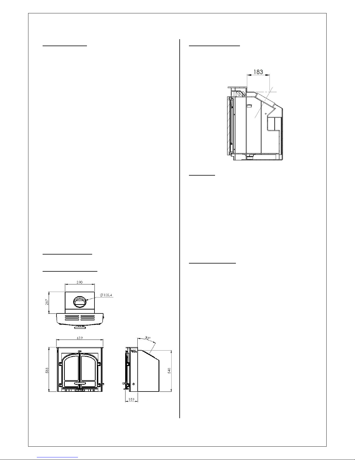
APPLIANCE DIMENSIONS
FLUE OUTLET POSITION
The flue outlet angle is 30°. The effective centre
dimension is shown below.
AIR SUPPLY
The room or space containing this appliance should
have purpose provided ventilation (where necessary)
in accordance with Building Regulations.
Due consideration should be given to air
requirements for any other appliance in the same
room or space.
Any air opening must be kept clear from blockage or
obstruction.
APPLIANCE OPENING
FLUE CONNECTION - All inset installations must have a
‘Throat Forming Lintel’, if a ‘Builders Opening Lintel
is present then this will have to be modified for
these units to be fitted.
This stove must be fitted on a hearth or base with
adequate load-bearing capacity.
The opening into which this stove is fitted should be
constructed wholly from non-combustible materials.
The dimensions of the opening should be at least
those shown in the diagram.
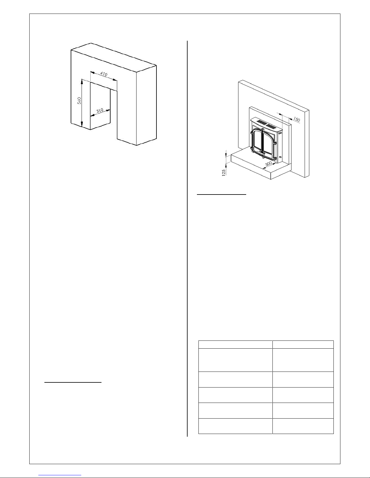
This appliance will fit into a standard 16” fireplace
opening if the clay fireback is removed.
Any non-combustible walls within 50mm of this
appliance should be at least 200mm thick and
should extend at least 300mm above the top of the
appliance and at least 1.2 metres above the hearth.
Any walls more than 50mm from the appliance may
be reduced to a thickness of 75mm. Ensure the interconnecting flue pipe also has adequate clearances to
combustible materials.
The walls surrounding the stove will become hot and
should therefore be finished in a heat resistant
plaster.
Do not hang pictures, plasma screen televisions or
ornaments above the stove, as these could be
damaged and could potentially create a fire hazard.
Please check the suitability of any
fireplace/surround for closed solid fuel appliances
before installation. Cleanburn Stoves cannot be held
responsible for any fault arising through incorrect
use or installation. Fire surround back panels
suitable for solid fuel are usually in three sections
and slabbed. Many fire surrounds are suitable only
for use with gas and electric fires and therefore not
suitable for solid fuel.
HEARTH REQUIREMENT S
A constructional hearth with a minimum thickness of
125mm should be provided. This constructional
hearth should extend to at least 300mm in front of
the stove and 150mm at the sides.
The constructional hearth should be made of solid
non-combustible material and can include any solid
non-combustible floor. The boundary of the hearth
must be clearly marked. This can be done by adding a
super-imposed hearth on top of the constructional
hearth – e.g. a slate slab on top of a solid concrete
floor.
FLUE REQUIREME NTS
The flue serving this appliance must be dry,
free from cracks and obstructions and be in
accordance with the designations shown in
Table 1.
The diameter of the flue should not be less
than 150mm and not more than 200mm.
If these requirements are not met the chimney
should be lined by a suitable method.
If there is no existing chimney then either a
prefabricated block chimney in accordance
with Building Regulations Approved Document
J or a twin-walled insulated stainless steel flue
to BS EN 1856 can be used. These chimneys
must be fitted in accordance with the
manufacturer’s instructions and Building
Regulations.
Flue Type
Minimum Designation
Masonry or flue block flue
with liner
T400 N2 D3 G
(BS EN 1443:2003)
Clay Flue Blocks
FB1 N2
(BS EN 1806:2006)
Clay/Ceramic Liners
B1 N2
(BS EN 1457:2009)
Concrete Liners
B2
(BS EN 1857:2003)
Factory Made Metal
Chimney
T400 N2 D3 G
(BS EN 1856-1:2003)
Table 1 – Minimum Flue Designations
The chimney/flue should have a vertical height
of at least 4.5 metres and should terminate in
accordance with Table 2.
If the chimney is believed to have previously
served an open fire installation, it is possible
that the higher flue gas temperature from the
stove may loosen deposits that were previously
firmly adhered, with the consequent risk of
flue blockage. It is therefore recommended
that the chimney is swept a second time within
a month of regular use after installation.
If you have any doubts about the suitability of
your chimney, consult your local
dealer/stockist.
Both the chimney and flue pipe must be
accessible for cleaning and if ANY part of the
chimney cannot be reached through the stove
(with baffle removed), a soot door must be
fitted in a suitable position.
FLUE DRAUGHT
If the draught exceeds the recommended
maximum, a draught stabiliser must be fitted
so that the rate of burning can be controlled
and to prevent over firing.
If the reading is less than the recommended
minimum then the performance of the
appliance will be compromised.
The flue draught should be checked under fire
at high output.
Minimum Draught – 1.2mm Water Gauge
Maximum Draught – 2.5mm Water Gauge
CLEARANCES TO COMBUSTIBLE MATERIALS
There should be no combustible materials for a
distance of 250mm either side of the stove or 325mm
above. No combustible furniture should be placed
any closer than 900mm from the front of the stove.
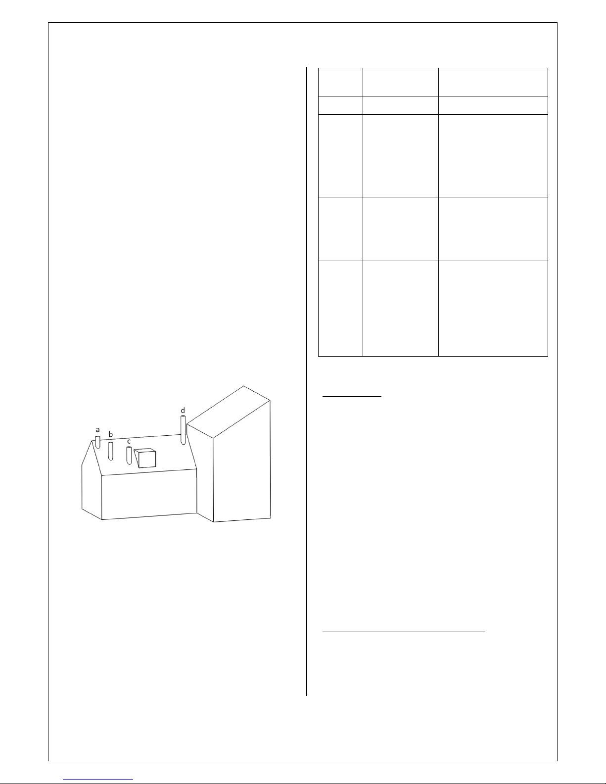
Position
Clearances to Flue
Outlet
a
At or within 600mm of
the ridge
At least 600m above the ridge
b
Elsewhere on a roof
(whether pitched or
flat)
At least 2300mm horizontally
from the nearest point on the
weather surface and:
highest point of intersection of
the chimney and the weather
surface or
c
Below (on a pitched
roof) or within
2300mm horizontally
to an openable
rooflight, dormer
window or other
opening.
At least 1000mm above the top
of the opening.
d
Within 2300mm of an
adjoining or adjacent
building, whether or
not beyond the
boundary.
At least 600mm above any part
of the adjacent building within
2300mm
Table 2 – Flue Terminal Positions
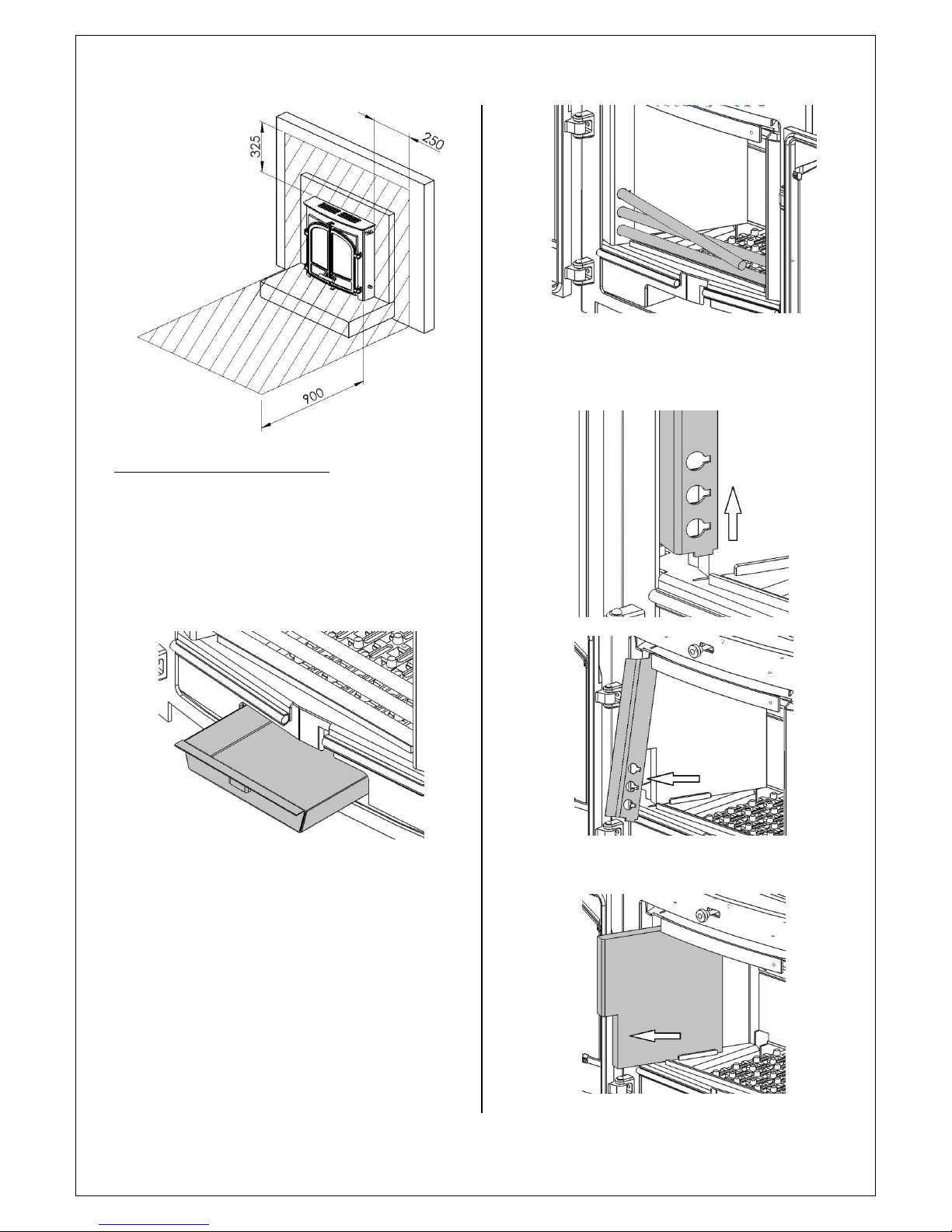
REMOVING INTERNAL COM PONENTS
All internal components must be removed prior to
fitting the stove. This will make handling the stove
easier; allow access to fixings and the flue outlet; as
well as protect the internal components from
damage during the installation process.
1. Open the door(s) and remove the ash pan.
2. Remove the fuel retainers by turning them
towards you until the pins at the ends of them
align with the cut-outs in the fuel retainer
supports and sliding them out.
3. Remove the fuel retainer supports by lifting them
free from the slots in the catch bar and swinging
the bottom ends out of the stove.
4. Slide the side bricks out.
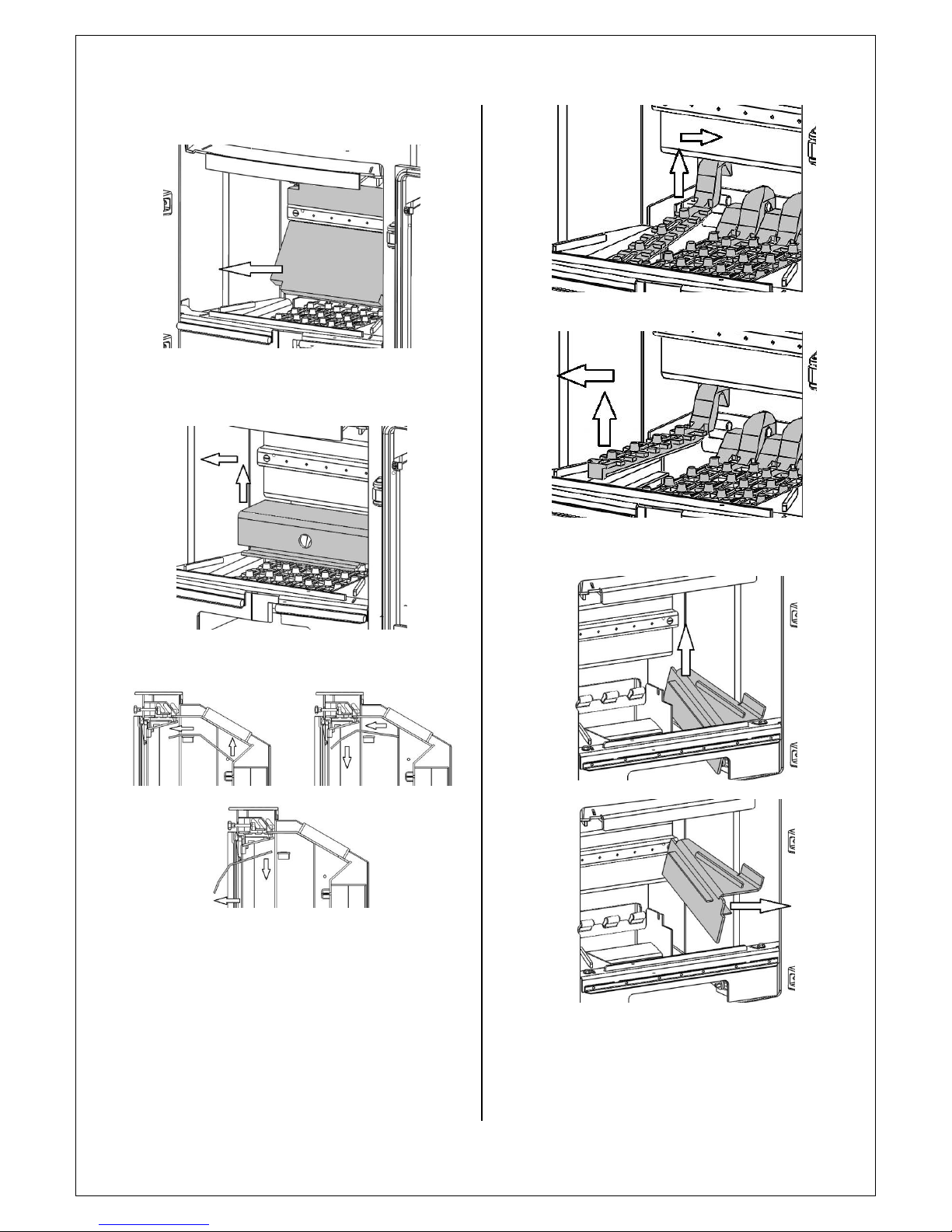
5. Remove the rear bricks.
6. Remove the lower rear brick support using the
finger hole provided to lift it from its slots.
7. Cut the cable ties and remove the baffle by rolling
it up over the baffle supports and out of the stove.
8. Remove the grate bars, starting with the high
bars.
9. Remove the firebox side plates.

10. Remove the catch bar/front plate.
11. Detach the cam bar linkage arm from the front
cam bar, rotate the cam bar and lift it out.
12. Lift out the rear cam bar along with the cam bar
linkage arm.
13. Lift out the primary air duct.
14. Lift out the primary air valve slider.
15. Undo the four M6 x 25mm screws and remove
the primary air valve and gasket.

16. Slide the primary air valve control arm all the
way to the left.
INSTALLATION INSTRUCTIONS
1. Using the diagram below, mark and drill a hole
using a 6mm drill bit to a depth of 70mm.
2. Slide the stove into position, ensuring that the
sealing rope is compressed against the fireplace
and fix using the supplied fixing screw (with
washer).
Any voids around the stove must be In-filled
with vermiculite concrete with a
recommended mix of six parts vermiculite to
one part Ordinary Portland Cement. This may
be carried out once the flue has been fitted
provided a suitable access hole for backfilling
is made in the chimney breast (see section on
connecting to a masonry chimney). Sufficient
water should be added so that when a handful
of the mixture is squeezed no more than one
or two drops of water are released.
FLUE CO NNECTION
If connecting to a stainless steel liner, a liner clamp
(HHN07/ARRT/003) will need to be used.
The clamp should be connected to the liner by a
proprietary flexible liner to single wall flue adaptor
using the three fixing holes in the clamp socket and
those provided in the flue adaptor.
The clamp can be attached to the bottom of the
liner without the appliance fitted. Apply fire
cement to the inside of the stove’s flue collar. The
stove can then be set back in the recess and the
liner clamped onto the stove by passing the clamp
fixing bolts through the flue outlet and securing in
place using the clamping flange and nuts and
washers provided. Make sure all joints are sealed
with fire cement.
If connecting to an existing masonry chimney it is
recommended that a flue forming pipe (short length
of flue pipe) is used and the void between the flue
forming pipe and the chimney filled with vermiculite
concrete.
A suitable access hole will need to be made in the
chimney breast to allow the back filling to be carried
out and then filled and sealed once the installation is
complete.

Alternatively a connection can be made using a
register plate although it will be necessary to allow
access for fitting the flue pipe to the register plate,
infilling with vermiculite concrete and sealing all
joints.
RE-ASSEMBLING THE STOVE
Refit all the internal parts by following the ‘removing
internal components’ instructions in reverse order.
Ensure that the firebox side plates are refitted using
the following procedure.
Insert the side plate so that the front end of it locates
under the front plate/catch bar as shown.
Ensure that the back end of the side plate is outside
the rear grate support as shown.
Lower the side plate into position so that the top
surface of it is flush with that of the front plate/catch
bar as shown.

COMMISSIONING
Upon completion of the installation allow a suitable
period of time for any fire cement and mortar to dry
out. A small fire may then be lit and the installation
checked to ensure the smoke and fumes are drawn
up the flue and emitted safely to atmosphere. The
stove should not be run at full output for at least 24
hours.
Read the Operating Instructions before lighting the
stove for the first time.
Leave the instructions and operating tool(s) with the
customer and advise them on -
Correct use of the appliance
The recommended fuel
Action to be taken should smoke or fumes be
emitted from the stove or installation.
The use of a fireguard when the stove is used in
the presence of children or the infirm.
Operating Instructions
Read the ‘General Guidance’ Section at the start of
these instructions before operating your stove for
the first time.
Allow sufficient clearance between the stove and
pictures, plasma screen televisions or ornaments etc,
as these could be damaged and could potentially
create a fire hazard (For more information read the
‘Clearance Distances to Combustibles’ section of the
installation instructions).
WARNING – This appliance will be hot when in
operation and due care should be taken. The
supplied operating tool or gloves may be used to
open the door and operate the air controls.
AEROSOLS
Do not use an aerosol spray on or near the stove
when it is alight.
AIR CONTROLS
Installed and used correctly this stove will burn
cleanly and efficiently. Therefore, to avoid the
disappointment of poor performance, please
familiarize yourself with the controls and their
recommended settings before use.
PRIMARY AIR
The slider at the bottom of the stove controls the
primary air. This provides a conventional air draught
to the bed of the fire. The control is open when the
slider is fully to the right.
SECONDARY & TERTIA RY AIR
Secondary air is controlled via the slider above the
door(s), it is this “Airwash” that keeps a clean and
uninterrupted view of the fire.
Tertiary air is fixed and enters the stove through the
holes at the back of the firebox. It aids in good
secondary combustion and reduces emissions into
the chimney and environment.
Warning! - This Appliance will be hot when in
operation and due care should be taken.
We advise that suitable gloves are used when
operating the Primary and Secondary air controls,
and when opening the door.
MULTIFUE L GRATE
Your Cleanburn Stove is fitted with a locomotive type
grate. So that de-ashing can be carried out cleanly
and easily, it is riddled from the outside of the stove

with the doors closed. The grate is designed to burn
both wood and solid fuels.
BURNING SOLID MINERAL FUELS
Place the operating tool over the riddling spigot and
push it up away from you. When left in that position,
air is directed under and up through the slots in the
firebed, giving the optimum conditions for burning
solid fuels.
It is important that the riddling tool is used to remove
the ash to ensure airflow through the firebed and
allow the fire to burn over the entire area of the
grate.
The ash pan should be emptied at least daily and ash
should never be allowed to build up over a period of
time as this will result in damage to the fire bars. The
flat end of the riddling tool can be used to carry the
ash pan.
BURNING WOOD
Pull the operating tool down and towards you. When
left in this position, air is restricted through the bed
of the fire providing a solid base to build up a bed of
ash. Surplus ash can be removed either by gentle
riddling or with a shovel.
It might prove beneficial when burning more reactive
fuels to leave the grate in a “neutral” position, thus
directing some under fire air and some over fire air to
the firebed.
LIGHTING
We recommend that you have two or three small
fires before you operate your stove to its maximum
heat output. This is to allow the paint to cure in
steadily and to give a long service life to the paint
finish. During this curing in process you may notice
an unpleasant smell. It is non-toxic, but for your
comfort we would suggest that during this period
you leave all doors and windows open.
To light the fire, load the firebox with starting fuel,
i.e. paper, dry sticks and/or firelighters. Fully open
both air controls (by sliding fully to the right) and
light the fire at the base.
Wood burning; Once the fire is established, close the
Primary Air Control (slide fully to the left) and add
more fuel as necessary. The secondary Air control can
now be used to regulate the burn rate of the stove.
When the stove is up to operating temperature the
operating tool or gloves should be used to operate
the air controls.
Smokeless fuel burning; Once the fire is established,
adjust the Secondary Air Control to a reduced setting
(slide to the left) and add more fuel as necessary. The
Primary Air control can now be used to regulate the
burn rate of the stove. When the stove is up to
operating temperature the operating tool or gloves
should be used to operate the air controls.
REDUCED COMBUSTION
In order to shut down the stove, reduce the primary
and secondary air by sliding both controls to the left.
If the controls are left in this position, the fire will be
starved of air and will die down.
If you want to revive the fire it is recommended that
the primary air control is opened first, and then the
secondary air control.
Warning!- The stove will remain hot for a
considerable time after the fire has been
extinguished.
RECOMME NDED FUELS
Cleanburn Stoves recommend that wood logs or
approved smokeless fuels are burnt in this appliance.
Burn only dry, well-seasoned wood, which should
have been cut, split and stacked for at least 12
months, with free air movement around the sides of
the stack to enable it to dry out.

Burning wet or unseasoned wood will create tar
deposits in the stove and chimney and will not
produce a satisfactory heat output.
Only authorised smokeless fuels may be used in
smoke control areas.
Warning! - Petroleum coke fuels or household waste
must not be burnt on this appliance.
This appliance should not be used as an incinerator.
No liquid fuels should be burnt on this appliance.
Should any difficulties arise over fuel quality or
suitability, consult your local approved coal merchant
or:
HETAS Ltd – Telephone 01242 673257 –
www.hetas.co.uk
Solid Fuel Association – Telephone 0800 600 000 –
www.solidfuel.co.uk
General Maintenance
Important! –In order to ensure continued
compliance with current Building Regulations and
Local Authority Byelaws, this appliance requires
regular maintenance of the following –
N.B. Refer to the ‘Removing Internal Components’
section of the installation instructions for details on
how to remove each component.
PERIODS OF PROLONGED NON-USE
If the stove is to be left unused for a prolonged
period, then it should be given a thorough clean to
remove ash and unburned fuel residues. To enable a
good flow of air through the appliance to reduce
condensation and subsequent damage, leave the air
controls fully open.
If the appliance has been unused for a long period,
such as during the spring and summer months, a
competent person should check the chimney for
potential obstructions before lighting the stove i.e.
get the chimney swept before the start of the
heating season.
AS NECESSARY
Baffle- This should be removed and cleaned at least
once a month to prevent any build up of soot or fly
ash that could lead to blocked flue ways and
dangerous fume emission.
If the baffle is removed the chimney/flue way can be
swept through the appliance.
Stove body – the stove is finished with a heat
resistant paint and this can be cleaned with a soft
brush. Do not clean the stove whilst it is hot; wait
until it has cooled down. The finish can be renovated
with proprietary stove paint.
Glass Panel(s) - Clean the glass panel when cool with
proprietary glass cleaner.
Highly abrasive substances should be avoided as
these can scratch the glass and make subsequent
cleaning more difficult.
Wet logs on heated glass, a badly aimed poker or
heavy slamming of the door could crack the glass
panel.
The glass will not fracture from heat.
Firebricks- In normal use, these can last for many
years. It is possible however, to crack them if logs are
continually jammed against them or if they are
frequently struck with a poker.
Check periodically for seriously cracked bricks, which
can be replaced with new, available from your dealer.
Door Catch- The door catch may require adjustment
to maintain the door seal. To adjust the catch, follow
the appropriate procedure below;
For Single-Door Stoves
Loosen the M8 nut.
Rotate the catch one complete turn to achieve
the correct door operation.
Tighten the M8 nut.
For Double-Door Stoves
Loosen the M6 grub screw.
Rotate the catch shaft one complete turn to
achieve the correct door operation.
Tighten the grub screw.
Rope- Check the rope around the door. If rope is
becoming detached, use Cleanburn Stoves rope glue
to reattach it. If the rope is in a poor condition, a
replacement rope kit may be ordered from the
Cleanburn Stoves spares range.
Chimney & Flue Ways- It is important that the
chimney, flue ways and any connecting flue pipe are
swept regularly. This means at least once a year for

smokeless fuels and at least twice a year for wood
and other fuels.
The baffle will need to be removed from its supports
in order to sweep the chimney (see ‘Removing
internal components’ instructions).
Only wire-centred sweeps’ brushes fitted with a
guide wheel should be used.
If it is not possible to sweep all parts of the chimney
through the appliance, ensure there is adequate
access to cleaning doors.
Seasonal use- If the appliance has been unused for a
long period of time, such as during the spring and
summer months, the chimney should be checked for
potential obstructions by a competent person before
lighting the stove.
Gaskets- all gaskets used on this appliance are
produced from a heat resistant material called
Manniglas. The glass gasket will have to be replaced
when a new piece of glass is fitted as the gaskets
become brittle after firing the stove. Over time you
may find that the gasket changes colour. This is due
to a reduction in the pigment used in the
manufacture of the product and no cause for
concern.
Trouble Shooting
FIRE WILL NOT BURN
Check that –
Chimneys and flue ways are clear.
A suitable fuel is being used.
There is an adequate air supply into the room.
An extractor fan is not fitted in the same room as
the stove.
Flue draught is above minimum level (see
installation instructions).
FIRE BLAZING OUT OF C ONTROL
Check that –
The door is tightly closed.
The air controls are in the closed position.
A suitable fuel is being used.
The glass is not loose.
The door rope seal is in good condition.
Flue draught is below maximum level (see
installation instructions).

Spares Information
Single Door

Spares Information
Right-Hand Door

Spares Information
Left-Hand Door

Spares Information
Single Door Handle

Spares Information
Double Door Handle

Spares Information
Single Door Body Spares

Spares Information
Double Door Body Spares
 Loading...