


OPERATOR'S MANUAL
CLEAN BURN COIL TUBE BOILER MODELS:
CB-200-CTB COIL TUBE BOILER with CB-500-5W Burner & Metering Pump
CB-350-CTB COIL TUBE BOILER with CB-551-5W Burner & Metering Pump
CB-500-CTB COIL TUBE BOILER with CB-551-H5-5W Burner & Metering Pump
230 V / 50 Hz
PUBLICATION DATE: 5/3/10, Rev. 7 CLEAN BURN PART #43186
WARNING: DO NOT assemble, install, operate, or maintain this equipment without first
reading and understanding the information provided in this manual. Installation and
service must be accomplished by qualified personnel. Failure to follow all safety precautions
and procedures as stated in this manual may result in property damage, serious personal injury
or death.
Copyright © 2010 Clean Burn, Inc. All rights reserved. No part of this publication may be reproduced, or distributed
without the prior written permission of Clean Burn, Inc. 34 Zimmerman Road, Leola, PA 17540, U.S.A. Subject to change
without notice. The Clean Burn logo is a trademark of Clean Burn, Inc. All other brand or product names mentioned are the
registered trademarks or trademarks of their respective owners.
I88729−B


DECLARATION OF CONFORMITY
Manufacturer: Clean Burn Inc.
34 Zimmerman Rd.
Leola, PA
USA
European Representative: TUV Rheinland North America
12 Commerce Rd.
Newtown CT. 06470
USA
Equipment: CTB-350 #90192
CTB-200 #90201
CTB-500 #90227
EMC Competent Body: TÜV Rheinland Product Safety GmbH
Am Grauenstein
D-51105 Köln
I hereby declare that the above named machinery complies with Essential Health and Safety Requirements of
the Industrial Machinery Directive (IMD - 98/37/EEC) as amended, with the Low Voltage Directive (LVD –
73/23/EEC) as amended, and with the Electromagnetic Compatibility Directive (EMC – 89/336/EEC) as
amended.
Safety Standard:
EN 230: 1990 Monobloc Oil Burners – Safety, Control, and Regulation Devices and Safety Times.
EN 292-1:1991 Safety of machinery - Basic concepts, general principles for design - Part 1 : Basic
terminology, methodology.
EN 292-2:1991+A1 Safety of machinery - Basic concepts, general principles for design - Part 2 : Technical
principles and specifications
EN 60204-1:2000 Safety of machinery. Electrical equipment of machines. General requirements.
EMC Standards:
EN 55014-1: 2000 Electromagnetic Compatibility – Requirements for Household Appliances, Electric
Tools, and Similar Apparatus. Part 1: Emission.
EN 55014-2: 2000 Electromagnetic Compatibility – Requirements for Household Appliances, Electric
Tools, and Similar Apparatus. Part 2: Immunity.
EN 50165: 1997 Electrical Equipment of Non-Electric Appliances for Household and Similar Purposes.
Safety Requirements.
Note: Above equipment is subject to an EMC Technical Construction File and Competent Body Certificate
Number AV 72032554 0001.
________________________
3 May, 2010 Ryan D. Gamber
Engineering Manager


TABLE OF CONTENTS
SECTION 1: INTRODUCTION.................................................................................... 1-1
Guide to this Manual........................................................................................................1-1
For Your Safety... ............................................................................................................. 1-2
Guidelines for CTB Usage ........................................................................................1-4
Guidelines for Used Oil Tanks..................................................................................1-5
Safety Labels .............................................................................................................1-6
SECTION 2: UNPACKING & PRE-INSTALLATION CONSIDERATIONS ................. 2-1
Removing the Shipping Crate ..........................................................................................2-1
Unpacking and Inspection................................................................................................2-1
CTB Component List .................................................................................................2-1
Pre-Installation Considerations ...........................................................................................2-2
Determining the CTB System Setup .............................................................................2-2
Selecting a Location ....................................................................................................2-2
SECTION 3: COIL TUBE BOILER ASSEMBLY ........................................................ 3-1
Understanding Assembly ....................................................................................................3-1
CTB (Single Boiler) Assembly ............................................................................................3-2
Installing the CTB on the Support Stand.......................................................................3-4
Dual-Stacked Boiler Assembly ...........................................................................................3-5
Assembling the Dual-Stacked Boiler ............................................................................3-5
Assembly for All Boilers .....................................................................................................3-8
Connecting the CTB ....................................................................................................3-8
Installing the Ceramic Sleeve........................................................................................3-9
Checking the Burner Nozzle and Electrodes ...............................................................3-11
Mounting the Burner on the Hinge Bracket .................................................................3-12
Installing the Connector Block ...................................................................................3-12
Installing the Oil Line Tubing ......................................................................................3-13
Installing the Air Line Tubing ......................................................................................3-14
Locking the Burner into Firing Position .......................................................................3-14
SECTION 4: COIL TUBE BOILER INSTALLATION .................................................. 4-1
Understanding Installation ...................................................................................................4-1
Important Safety Guidelines .........................................................................................4-1
Typical Installation Diagrams........................................................................................4-3
Combustion Air Requirements .....................................................................................4-5
Oil Tank Installation Specifications......................................................................................4-7
Installing the Tank Vent and Emergency Vent ...............................................................4-8
Installing the Metering Pump ...............................................................................................4-9
Preparing for Installation ..............................................................................................4-9
Standard Mounting: Vertical Positioning .......................................................................4-9
Alternate Mounting: Horizontal Positioning .................................................................4-11
Connecting Water to the Coil Tube Boiler.........................................................................4-12
Filling the CTB with Water ........................................................................................4-12
Installing the Suction Oil Line Components........................................................................4-13
Installing the Pressure Relief Oil Line Back to the Tank .....................................................4-16

TABLE OF CONTENTS
SECTION 4: CTB INSTALLATION (continued) .............................................................
Installing the Pressure Oil Line Components ......................................................................4-17
Installing the Compressed Air Line....................................................................................4-17
Wiring the Coil Tube Boiler ..............................................................................................4-18
Wiring to the CTB .....................................................................................................4-18
Wiring to the Metering Pump .....................................................................................4-19
Wiring the Load Loop Circulator ...............................................................................4-19
Installing the Stack ...........................................................................................................4-20
Installing the Interior Stack.........................................................................................4-22
Installing the Barometric Damper ...............................................................................4-23
Installing the Optional Stack Safety Switch .................................................................4-24
Resetting the Stack Safety Switch ........................................................................4-25
Understanding the function of the Stack Safety Switch ..........................................4-25
Installing the Stack Penetration...................................................................................4-26
Installing the Exterior Stack........................................................................................4-26
Installing the Stack Cap .............................................................................................4-26
Installing the Draft Inducer ......................................................................................... 4-26
Installing the Wall Thermostat or Aquastat ........................................................................4-28
Replacing the Wall Thermostat Batteries ....................................................................4-28
Inspecting the CTB Installation .........................................................................................4-29
SECTION 5: METERING PUMP PRIMING ................................................................5-1
Understanding Metering Pump Priming .......................................................................... 5-1
Required Tools and Materials ......................................................................................5-1
Priming the Metering Pump.................................................................................................5-2
Vacuum Testing the Oil Pump.............................................................................................5-4
SECTION 6: STARTING AND ADJUSTING THE BURNER ......................................6-1
Understanding Burner Startup and Adjustment ............................................................... 6-1
Preparing the Hydronics System for Burner Startup ........................................................ 6-1
Preparing the Burner for Startup ...................................................................................... 6-1
Starting the Burner ........................................................................................................... 6-3
SECTION 7: RESETTING THE OIL PRIMARY CONTROL .......................................7-1
Understanding the Danfoss Oil Primary Control ..................................................................7-1
Resetting the Danfoss Oil Primary Control ..........................................................................7-1
SECTION 8: ADJUSTING THE DRAFT OVER FIRE ................................................8-1
Understanding the Importance of Draft ...............................................................................8-1
Checking for Correct Draft Over Fire .................................................................................8-1
Understanding the Effect of Exhaust Fans on Draft .......................................................8-2
Checking Draft Over Fire to Determine Severity of Backdraft ......................................8-2
Adjusting Draft Over Fire with a Draft Inducer Installed ...............................................8-3

TABLE OF CONTENTS
SECTION 9: MAINTENANCE ....................................................................................9-1
Understanding Maintenance................................................................................................9-1
Annual Preventative Maintenance & Burner Tune-up ..........................................................9-1
Cleaning the Canister Filter .................................................................................................9-2
Servicing the Metering Pump ..............................................................................................9-3
Cleaning the Check Valve / Screen .....................................................................................9-4
Cleaning Ash from the CTB................................................................................................9-5
Cleaning the Oil Tank .........................................................................................................9-6
End of Season Maintenance ...............................................................................................9-6
SECTION 10: THE CTB HYDRONIC SYSTEM .......................................................10-1
Understanding the CTB Hydronic System .........................................................................10-1
Special Safety Guidelines ...........................................................................................10-1
CTB System Function and Configuration....................................................................10-2
CTB Setup Options...................................................................................................10-4
Guidelines for CTB Setup and Operation ..........................................................................10-7
Guidelines for Preventing Oxygen Contamination ........................................................10-8
Guidelines for Initial Cleaning and Maintaining Water Quality ......................................10-8
Guidelines for CTB Operation ...................................................................................10-8
SECTION 11: TROUBLESHOOTING ......................................................................11-1
CTB Sequence of Operation ............................................................................................11-1
Flow Chart ......................................................................................................................11-2
Troubleshooting Tables ....................................................................................................11-3
APPENDIX A
Detailed CTB Specifications .............................................................................................. A-1
CTB Technical Specifications ..................................................................................... A-1
Burner Technical Specifications................................................................................... A-2
CTB Hydronic Specifications......................................................................................A-2
CTB Accessories and Parts Reference........................................................................A-3
CB-200-CTB Dimensions .......................................................................................... A-5
CB-350-CTB Dimensions .......................................................................................... A-6
CB-350-CTB Dual Stacked Boiler Dimensions ..........................................................A-7
CB-500-CTB Dimensions .......................................................................................... A-8
CB-500-CTB Dual Stacked Boiler Dimensions ..........................................................A-9
Burner Components ........................................................................................................ A-10
CB-500-CE 5W Series Burner Components ............................................................ A-10
CB-500-CE 5W and CB-551-CE 5W Preheater Block Assembly Detail ................. A-12
CB-551-H5 CE 5W Preheater Block Assembly Detail ............................................. A-14
Burner Electrode Specifications ................................................................................ A-16
Removing the Nozzle for Cleaning.............................................................................A-17
CB-200-CTB Components.............................................................................................A-18
CB-350-CTB Components.............................................................................................A-20
CB-500-CTB Components.............................................................................................A-22

APPENDIX B
Wiring Diagrams ............................................................................................................... B-1
Burner Wiring Diagram (CB-500-CE 5W and CB-551-CE 5W) ................................ B-1
Burner Wiring Diagram (CB-551-H5 CE 5W)............................................................ B-2
Control Box Wiring Diagram ...................................................................................... B-3
Metering Pump Wiring Schematic ............................................................................... B-4
CTB Ladder Schematic..................................................................................................... B-5
APPENDIX C
Additional Installation and Maintenance Requirements (United Kingdom ONLY) ............... C-1
APPENDIX D
CTB Service Record.........................................................................................................D-1
TABLE OF CONTENTS

Coil Tube Boiler Operator's Manual: Models CB-200-CTB, CB-350-CTB and CB-500-CTB (230 V / 50 Hz)
SECTION 1: INTRODUCTION
Guide to this Manual
This manual contains all the information necessary to safely install and operate the Clean Burn Coil
Tube Boilers (CTB), Models CB-200-CTB, CB-350-CTB, and CB-500-CTB. Consult the Table of
Contents for a detailed list of topics covered. You'll find this manual's step-by-step procedures easy to follow
and understand. Should questions arise, please contact your Clean Burn dealer before starting any of the
procedures in this manual.
As you follow the directions in this manual, you'll discover that assembling and operating the Clean
Burn CTB involves six basic activities as outlined here:
• UNPACKING & PRE-INSTALLATION CONSIDERATIONS ............................ (Section 2)
• ASSEMBLY....................................................................................................... (Section 3)
• INSTALLATION ................................................................................................ (Section 4)
• OPERATION
• Oil Pump Priming ................................................................................ (Section 5)
• Starting and Adjusting the Burner ..................................................... (Section 6)
• Resetting the Oil Primary Control...................................................... (Section 7)
• Adjusting the Draft .............................................................................. (Section 8)
• MAINTENANCE ................................................................................................ (Section 9)
• THE CTB HYDRONICS SYSTEM.....................................................................(Section 10)
The manual also contains important and detailed technical
reference materials which are located at the back of the manual
in the Appendixes.
WARNING!
Please read all sections carefully--including the following
safety information--before beginning any installation/
operation procedures; doing so ensures your safety and the
optimal performance of your Clean Burn Coil Tube
Boiler.
STOP
YOUR SAFETY IS AT STAKE!
DO NOT INSTALL, OPERATE OR
MAINTAIN THIS EQUIPMENT
WITHOUT FIRST READING
AND UNDERSTANDING THE
OPERATOR'S MANUAL!
1-1

Coil Tube Boiler Operator's Manual: Models CB-200-CTB, CB-350-CTB and CB-500-CTB (230 V / 50 Hz)
For Your Safety...
For your safety, Clean Burn documentation contains the following types of safety statements (listed here
in order of increasing intensity):
• NOTE: A clarification of previous information or additional pertinent information.
• ATTENTION: A safety statement indicating that potential equipment damage may occur if
instructions are not followed.
CAUTION: A safety statement that reminds of safety practices or directs attention to unsafe
practices which could result in personal injury if proper precautions are not taken.
WARNING: A strong safetystatement indicating that a hazard exists which can result in
injury or death if proper precautions are not taken.
DANGER! The utmost levels of safety must be observed; an extreme hazard exists which
would result in high probability of death or irreparable serious personal injury if proper
precautions are not taken.
In addition to observing the specific precautions listed throughout the manual, the following general
precautions apply and must be heeded to ensure proper, safe boiler operation.
DANGER! DO NOT create a fire or explosion hazard by storing or using gasoline or other
flammable or explosive liquids or vapors near your boiler.
DANGER! DO NOT operate your CTB if excess oil, oil vapor or fumes have
accumulated in or near your boiler. As with any oil burning appliance, improper installation,
operation or maintenance may result in a fire or explosion hazard.
WARNING: DO NOT add inappropriate or hazardous materials to your used oil, such as:
• Anti-freeze
• Carburetor cleaner
• Paint thinner
• Parts washer solvents
• Gasoline
• Oil additives
• Any other inappropriate/hazardous
material
WARNING: Burning chlorinated materials (chlorinated solvents and oils) is illegal, will
severely damage your heat exchanger, immediately void your warranty, and adversely affect
the proper, safe operation of your CTB. Instruct your personnel to never add hazardous
materials to your used oil.
1-2

Coil Tube Boiler Operator's Manual: Models CB-200-CTB, CB-350-CTB and CB-500-CTB (230 V / 50 Hz)
For Your Safety... (continued)
WARNING: Never alter or modify your CTB without prior written consent of
Clean Burn, Inc. Unauthorized modifications or alteration can adversely affect the proper,
safe operation of your boiler.
WARNING: The burner which is shipped with your Clean Burn CTB is to be used only
with your boiler according to the instructions provided in this manual. DO NOT use the
burner for any other purpose!
WARNING: For the safe installation and operation of the CTB, the boiler cannot be raised
above the floor level, suspended from the ceiling, installed on a raised platform, or placed over top
of any equipment, office space, parts room, etc. or installed in any other manner than directly on a
concrete floor.
WARNING: Electrical installation of the boiler is to be performed only by qualified
personnel (i.e. licensed electrician/engineer). Improper electrical installation can adversely
affect the proper, safe operation of the boiler and may cause serious personal injury/death.
WARNING: Install the boiler in an area away from the main shop traffic. It is essential for
personal safety that only manufacturer-trained, qualified personnel have access to operate
and maintain the boiler.
WARNING: DO NOT operate your boiler when the ambient temperature is above
35o C (95o F).
WARNING: The Best Operator is a Careful Operator! By using common sense,
observing general safety rules, and adhering to the precautions specific to the equipment, you,
the operator, can promote safe equipment operation. Failure to use common sense, observe
general safety rules, and adhere to the precautions specific to the equipment may result in
equipment damage, fire, explosion, personal injury and/or death.
WARNING: The installation, operation, and maintenance of this equipment must be
accomplished by qualified personnel and in compliance with the specifications in the
Clean Burn Operator's Manual and with all national, state, and local codes or authorities
having jurisdiction over environmental control, building inspection and fuel, fire and
electrical safety.
Failure to comply with these standards and requirements may result in equipment
damage, fire, explosion, personal injury and/or death.
1-3

Coil Tube Boiler Operator's Manual: Models CB-200-CTB, CB-350-CTB and CB-500-CTB (230 V / 50 Hz)
For Your Safety... (continued)
Guidelines for Coil Tube Boiler Usage
• This boiler is listed for commercial and/or industrial use only; it is not listed for residential
use.
• This boiler is designed to burn the following fuels:
• Used crankcase oil up to 50 SAE
• Used transmission fluid
• Used hydraulic oils
• #2, #4, and #5 fuel oils
NOTE: Used oils may contain other substances, including gasoline, that may hinder
performance.
• Make sure you comply with all environmental regulations concerning the use of your boiler.
These regulations require that:
• Your used oil is generated on-site. You may also accept used oil from
"do-it-yourself" oil changers.
• Hazardous wastes, such as chlorinated solvents, are NOT to be mixed with your
used oil.
• The flue gases are vented to the outdoors with an appropriate stack.
• Your used oil is recycled as fuel for "heat recovery". DO NOT operate your boiler
in warm weather just to burn oil.
Contact your Clean Burn dealer for current environmental regulations.
• If your CTB ever requires service, call your Clean Burn dealer. DO NOT allow untrained,
unauthorized personnel to service your CTB. Make sure that your boiler receives annual
preventative maintenance to ensure optimal performance.
1-4

Coil Tube Boiler Operator's Manual: Models CB-200-CTB, CB-350-CTB and CB-500-CTB (230 V / 50 Hz)
For Your Safety... (continued)
Guidelines for Used Oil Tanks
For the safe storage of used oil and the safety of
persons in the vicinity of the used oil supply tank,
ensure that your tank installation adheres to the
following safety guidelines:
• The tank installation must meet all
national and local codes. Consult your
local municipal authorities for more
information as necessary.
• Review and adhere to the safety
guidelines for used oil supply tanks
as stated in the WARNING shown.
• Ensure that the tank for your boiler
installation complies with all code and
safety requirements as stated here. If the
tank does not comply, DO NOT use it.
• If you do not have a copy of the tank
safety label pictured at right, please
contact your Clean Burn dealer for the
label, which is to be affixed directly on
your used oil supply tank.
1-5

Coil Tube Boiler Operator's Manual: Models CB-200-CTB, CB-350-CTB and CB-500-CTB (230 V / 50 Hz)
For Your Safety... (continued)
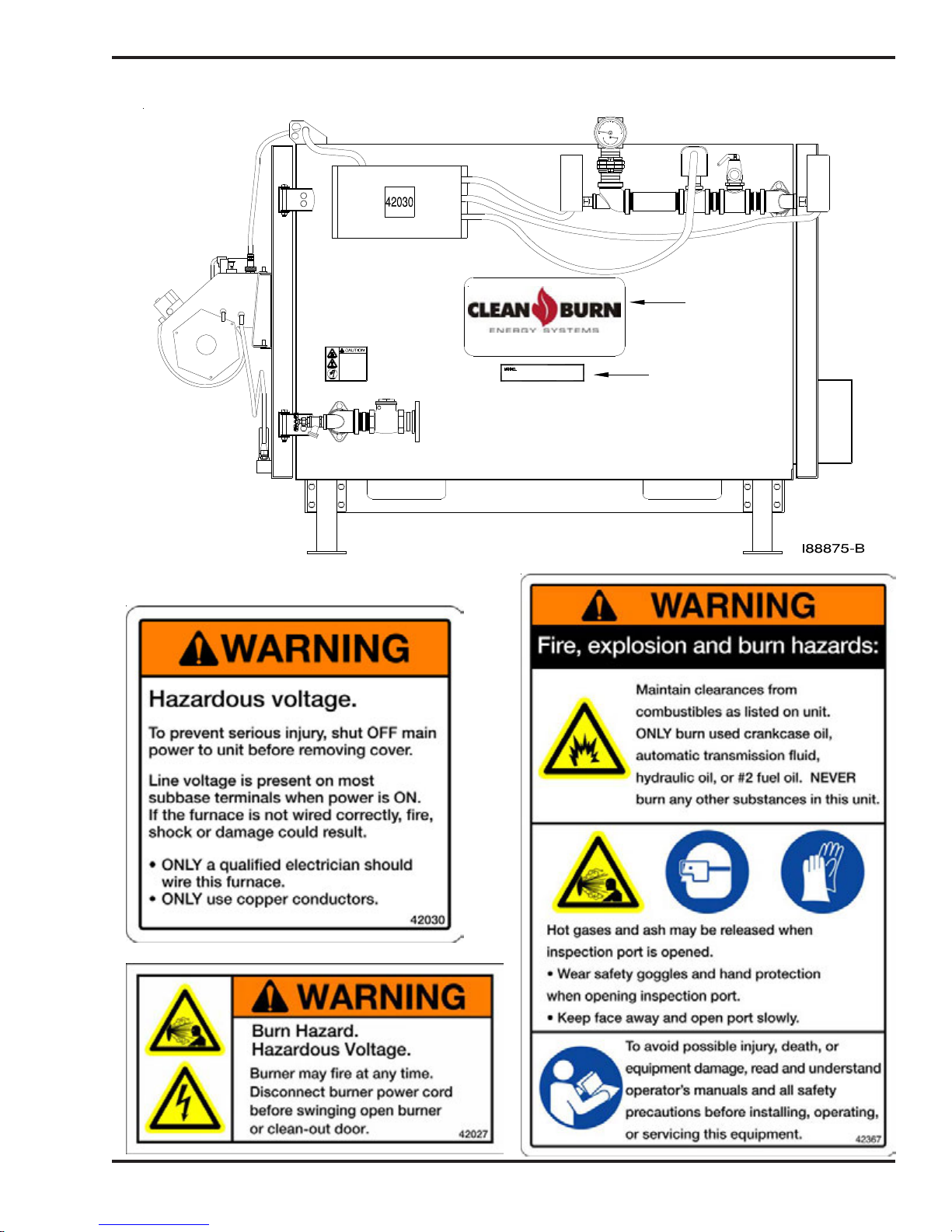
Safety Labels
Following are the locations and descriptions of all labels on your CTB. The following illustrations show
the location of ALL labels on your boiler. Please note that some labels denote model number, model
description, etc. while others contain important safety messages.
Each Safety Label contains an important safety message starting with a key word as discussed earlier in
this section (e.g. ATTENTION, CAUTION, WARNING, DANGER). For your safety and the safe
operation of your CTB, review all labels and heed all safety messages as printed on the labels.
If any labels on your Clean Burn CTB ever become worn, lost or painted over, please call your Clean
Burn dealer for free replacements.
CTB Cabinet Labels
Label Part # Description
42367 C.B. Safety Warning Label (multiple messages - fire/shock/burn hazards)
42457 Made in USA/Patent Pending Label
42027 Burn Hazard / Hazardous Voltage Warning Label
42308 Header Label
42481 CB-200-CTB CE Data Label
42306 CB-350-CTB CE Data Label
42503 CB-500-CTB CE Data Label
42030 Electrical Shock Hazard Warning Label
42421 CTB Hot Water Caution Label
42216 C.B. Logo Label - 22 cm x 11 cm (8.75" x 4.25")
42297 C.B. Logo Label - 51 cm x 20 cm (20" x 8")
42465 CB-200-CTB Model # Label
42286 CB-350-CTB Model # Label
42502 CB-500-CTB Model # Label
42367
42308
42481
42306
42503
42457
DATE
CODE
1-6
AIR
OIL
I88785−B
Coil Tube Boiler Operator's Manual: Models CB-200-CTB, CB-350-CTB and CB-500-CTB (230 V / 50 Hz)
CTB Cabinet Labels (continued)
42216
42497
42421
CTB Cabinet Safety Labels
Burn Hazard.
Fittings, piping, and
boiler surface may be
extremely hot.
Pipes contain hot water.
Do NOT touch without
wearing protective
gloves.
www.cleanburn.com
CB *** CTB
42216
42286
42465
42286
42502
1-7

Coil Tube Boiler Operator's Manual: Models CB-200-CTB, CB-350-CTB and CB-500-CTB (230 V / 50 Hz)
For Your Safety... (continued)
CTB Cabinet Safety Labels (continued)
NO.
MULTI−OIL HEATING SYSTEM
FOR COMMERCIAL OR INDUSTRIAL USE ONLY.
42308
CTB−200−CE
INPUT RATING W/NO 2 FUEL OIL (KW/HR)
3.8
3.8
3.8
3.8
3.8
3.8
46
MAXIMUM FUSE SIZE / WITH OPTIONS
14
14 2.7
14
18
18
18 4.0
POWER
1/20
1/10
400
1/6 230 1.10 50
1/10 230 .56 50
1/3
.96
.96
.96
1.24
1.24
1.24
46
230
230
230
220 1.5 50
230
2.5
2.5
3.4
4.0
SIDE
.40
.56
1.65
1.8
6
15/20
58.6
.17
.19
.17
.23
.28
.28
−.06 (1.5MM)
16
7616122
HZ
50
50
50
50
FOR COMMERCIAL OR INDUSTRIAL USE ONLY.
42481
1-8

Coil Tube Boiler Operator's Manual: Models CB-200-CTB, CB-350-CTB and CB-500-CTB (230 V / 50 Hz)
CTB Cabinet Safety Labels (continued)
INPUT RATING W/NO 2 FUEL OIL (KW/HR)
CTB−500−CE
147.0
13.5
13.5
13.5
13.5
13.5
13.5
46
122
MAXIMUM FUSE SIZE / WITH OPTIONS
16
16
22
20
16
16
POWER
1/20
1/10
500
1/2 230 50
1/4
1/2
2.5
2.5
2.1
2.3
2.5
2.5
−.06 (1.5mm)
0.17
0.17
0.15
0.16
0.17
0.17
16
7616
HZ
50
50
50
50
50
1.1
1.1
1.5
1.4
1.1
1.1
46
SIDE
230
230
230
230
230
0.40
0.70
1.9
2.7
1.3
3.0
10.0
20.0
FOR COMMERCIAL OR INDUSTRIAL USE ONLY.
42503
1-9

Coil Tube Boiler Operator's Manual: Models CB-200-CTB, CB-350-CTB and CB-500-CTB (230 V / 50 Hz)
For Your Safety... (continued)
CTB Burner Labels
Label
Part # Description
42004 Burner Safety Warning Label (High Voltage/Moving Parts Hazard)
42235 Burner Safety Warning Label (Fire/Explosion Hazard - Burner Installation and Service)
42470 CB-500-CE-5W Burner Model/Serial Number
42483 CB-551-CE Burner Model/Serial Number
42508 CB-551-H5-CE Burner Model/Serial Number
42229 C.B. Logo/Burner Description Label
42482 Burner Safety Warning Label (Fire/Explosion Hazard - Reset Button)
42309 CE Mark Label
42023 Burner Power Label
CTB BurnerSafety Labels
42470
42483
42508
I88854−B
1-10

Coil Tube Boiler Operator's Manual: Models CB-200-CTB, CB-350-CTB and CB-500-CTB (230 V / 50 Hz)
SECTION 2: UNPACKING & PRE-INSTALLATION
CONSIDERATIONS
Before assembling your coil tube boiler (CTB) , you must accomplish the following activities described
in this section:
• Removing the Shipping Crate
• Unpacking and Inspecting All Components
• Warranty Registration
• Review the Pre-Installation Considerations
Removing the Shipping Crate
1. Carefully remove the top boards of the shipping crate. Then remove the front, back, and side
panels.
2. Remove the bolts holding the boiler on the shipping pallet.
3. Carefully lift the CTB off the shipping pallet with a fork lift.
ATTENTION: DO NOT attempt to slide the CTB out of the shipping crate--you may damage the
cabinet.
Unpacking and Inspection
Following is an itemized list of all components you should have received in your Clean Burn Coil Tube
Boiler shipment. Open all shipping containers and inspect all components according to the list.
Immediately notify the freight company and your Clean Burn dealer in case of shipping damage or
shortage(s). Keep all components together so you will have them as needed for CTB assembly and
installation.
Model CB-200-CTB, CB-350-CTB and CB-500-CTB Component List
• Coil Tube Boiler with factory-installed controls
(including operating aquastat, high temperature cut-off, flow switch, relief valve, and check valve)
Components packed inside boiler:
• Ceramic combustion chamber sleeve
• Combustion chamber sleeve mounting stand
• Ceramic target (pre-mounted)
• Canister filter
• Vacuum gauge
• Check valve with screen (for tank)
• Boiler gauge
• Tube sealant
• Burner hook-up kit
• Barometric damper
• Burner
• Oil pump (metering pump)
• CTB base stand with hardware
• Draft Inducer
2-1

Coil Tube Boiler Operator's Manual: Models CB-200-CTB, CB-350-CTB and CB-500-CTB (230 V / 50 Hz)
Pre-Installation Considerations
The following information is critical to the proper installation of your Clean Burn Coil Tube Boiler
system; read this section carefully before starting any other procedures.
Determining the CTB System Setup
Before installing the CTB, you must determine the following which relate to your installation:
(1) The type of oil storage tank you will be using (related information in Section 4)**
(2) The positioning of your oil pump (related information in Section 4)
(3) The appropriate size for your oil lines (related information in Section 4)
(4) The electrical requirements for your CTB installation (related information in Section 4)
(5) The type of hydronic installation you will be using (related information in Section 10)
**IMPORTANT NOTE: If you are installing an inside oil tank in the same room as the boiler, you
must allow a 1.5 m (5 ft) minimum clearance between the tank and the boiler. The oil tank should be set and
installed in position BEFORE the boiler is installed.
Selecting a Location
The location you select for your CTB must allow the following:
• Installation in a dedicated boiler/mechanical room with a minimum fire rating of two (2)
hours.
• Installation on a substantial, level, non-combustible concrete floor (minimum 10 cm / 4" thick).
• Proper clearances from combustibles. Verify according to your local safety codes.
• Safe, easy access for servicing.
• Adequate combustion air per national and local codes.
• Proper stack installation and materials.
WARNING: For the safe installation and operation of the CTB, the boiler cannot be raised
above the floor level, suspended from the ceiling, installed on a raised platform, or placed over
top of any equipment, office space, parts room, etc. or installed in any other manner than directly on a
concrete floor.
2-2

Coil Tube Boiler Operator's Manual: Models CB-200-CTB, CB-350-CTB and CB-500-CTB (230 V / 50 Hz)
Selecting a Location (continued)
Adhere to the following minimum clearances from combustible surfaces. Specifications are also
provided for servicing clearance. Be sure to check local codes which may differ from these
specifications. Refer to Figure 2A for a single CTB and Figure 2B for dual-stacked CTB boilers.
Fig. 2A and 2B Description Clearance from Combustibles Clearance for Service
A Above 46 cm (18") 46 cm (18")
B Front 61 cm (24") 122 cm (48")
C Stack 46 cm (18") 46 cm (18")
D Rear 15 cm (6") 102 cm (40")
E L.H. Side 15 cm (6") * 15 cm (6") *
F R.H. Side 76 cm (30") 76 cm (30")
G Bottom 15 cm (6") 15 cm (6")
* 91 cm (36") may be required
C
E
L.H. SIDE
G
C
E
L.H. SIDE
A
F
R.H. SIDE
AIR OIL
B
Figure 2A - Single Boiler Minimum Installation Clearances
C
F
A
E
R
O
M
DRAFT
S
E
L
S
I88734−B
O
R
M
E
DRAFT
L
E
S
S
C
D
C
G
Figure 2B - Dual-Stacked Boilers Minimum Installation Clearances
AIR OIL
B
AIR
OIL
D
I88733−C
2-3

Coil Tube Boiler Operator's Manual: Models CB-200-CTB, CB-350-CTB and CB-500-CTB (230 V / 50 Hz)
2-4

Coil Tube Boiler Operator's Manual: Models CB-200-CTB, CB-350-CTB and CB-500-CTB (230 V / 50 Hz)
SECTION 3: COIL TUBE BOILER ASSEMBLY
Understanding Assembly
Assembling your Clean Burn Coil Tube Boiler (CTB) is a multi-step process. Note that some assembly
procedures apply only to certain CTB installations or configurations (i.e. single model or dual-stacked
boilers); the assembly procedures are outlined below as they appear in this section.
Be sure to refer to the appropriate instructions for your CTB configuration.
Single Boiler Assembly Only
• Installing the CTB on the Support Stand
Dual-Stacked Boiler Assembly Only
• Assembling the Dual-Stacked Boiler
Assembly For All Boilers
• Connecting the CTB
• Installing the Ceramic Sleeve
• Checking the Burner Nozzle and Electrodes
• Installing the Connector Block on the CTB Door
• Installing the Oil Line Tubing
• Installing the Air Line Tubing
• Locking the Burner into Firing Position
3-1

Coil Tube Boiler Operator's Manual: Models CB-200-CTB, CB-350-CTB and CB-500-CTB (230 V / 50 Hz)
Single Boiler Assembly
CB−350−CTB
(230 V/50 Hz)
SHOWN
1
DETAIL OF ITEM 21
2
29
17
16
15
14
18
13
12
11
19
20
21
22
5
6
4
10
8
3
23
24
7
9
26
25
30
CIRCULATOR
(USER SUPPLIED)
28
27
Figure 3A - Single Boiler Assembly Component Detail
31
I88747−C
3-2

Coil Tube Boiler Operator's Manual: Models CB-200-CTB, CB-350-CTB and CB-500-CTB (230 V / 50 Hz)
CB‐350‐CTBCEPARTSLIST
NUMBER QTY PART # DESCRIPTION
31 1 90188 BASE
30 1 33529 COIL RELAY 240 VAC 30 A
29 1 33331 TERMINAL BLOCK
28 1 33340 TRANSFORMER 230V-24V
27 1 33328 RELAY DPDT
26 1 33352 RELAY DELAY
25 1 33486 TERMINAL BLOCK ASSEMBLY
24 1 33286 SWITCH DPDT
23 1 33338 AMBER LIGHT
22 1 27058 CONTROL BOX LID
21 1 12240 CONTROL BOX
20 1 33105 SNAP IN BUSHING
19 2 27158 L-BRACKET
18 1 33534 CONNECTOR CORD
17 1 31176 INSULATION – DOOR
16 1 11405 DOOR W.A.
15 1 21077 PORT LID
14 1 14084 ROPE GASKET
13 1 11583 BURNER MOUNT W.A.
12 1 11582 HINGE BRACKET W.A.
11 1 13141 ACCUMULATOR BLOCK ASSEMBLY
10 1 14272 UPPER PIPE ASSEMBLY
9 1 14293 CHECK VALVE AND PIPE ASSEMBLY
8 1 33330 GUAGE BOILER TEMP/PRESS
7 1 35048 RELIEF VALVE 3/4” MALE
6 1 35123 FLOW SWITCH TACO
5 1 28149 HIGH TEMP CUT-OFF
4 1 35079 COIL FLANGE 1-1/4”
3 1 28150 AQUASTAT
2 1 31166 INSULATION PANEL
1 1 11380 PANEL 350 REAR W.A.
PARTSTHATDIFFERONTHE CB‐200‐CTBCE
NO QTY PART # DESCRIPTION
31 1 90200 BASE
17 1 31216 INSULATION 200 DOOR
16 1 11540 DOOR W.A.
10 1 14307 UPPER PIPE ASSEMBLY
9 1 14298 CHECK VALV E AND PIPE A SSY
4 1 35116 COIL FLANGE 1” NPT
2 1 31215 INSULATION PANEL
1 1 11539 PANEL 200 REAR W.A.
Refractory Cylinder 21120 21140 21174
Refractory Cylinder Stand 27155 27190 27200
PARTSTHATDIFFERONTHE CB‐500‐CTBCE
NO QTY PART # DESCRIPTION
31 1 90206 BASE
17 1 31240 INSULATION 500 DOOR
16 1 11564 DOOR W.A.
10 1 14315 UPPER PIPE ASSEMBLY
9 1 14314 CHECK VALV E AND PIPE A SSY
4 1 35121 COIL FLANGE 1 ½ ” NPT
2 1 31239 INSULATION PANEL
1 1 11563 PANEL 500 REAR W.A.
200-CTB 350-CTB 500-CTB
3-3

Coil Tube Boiler Operator's Manual: Models CB-200-CTB, CB-350-CTB and CB-500-CTB (230 V / 50 Hz)
Single Boiler Assembly
Installing the CTB on the Support Stand
WARNING: Use extreme caution when moving and lifting the CTB (with a forklift) into
place on the support stand. One CTB can weigh up to 907 kg (2000 pounds). Clean Burn recommends placing safety blocking underneath the unit until it is properly installed and secured on the support stand.
Failure to follow these basic safety guidelines may result in serious personal injury and/or damage to
the unit.
1. Refer to Figure 3A to become familiar with the components required for CTB assembly.
2. Assemble the CTB support stand as shown in Figure 3B, using the hardware provided.
3. Move the support stand into the approximate position where the CTB is to be installed, and place
blocks (approximately 25 cm /10 inches high) inside the stand to provide safety support for the
boiler.
4. Use a forklift to carefully lift the CTB into position over top of the support stand.
WARNING: Secure the boiler to the forklift prior to lifting to prevent possible equipment
damage or personal injury.
5. Lower the boiler down onto the safety blocks positioned inside the support stand.
6. Insert bolts (provided) into the keyhole slots in the boiler, and then lift the stand in position
against the bottom of the boiler.
7. Tighten the bolts to firmly attach the stand to the bottom of the boiler.
8. Carefully lift the assembled boiler (with stand) off the safety blocks and move the unit into place.
9. Proceed with the remainder of boiler assembly procedures marked for ALL CTB Models.
Figure 3B - Assembling the Support Stand
I88816-A
3-4
Coil Tube Boiler Operator's Manual: Models CB-200-CTB, CB-350-CTB and CB-500-CTB (230 V / 50 Hz)
Dual-Stacked Boiler Assembly
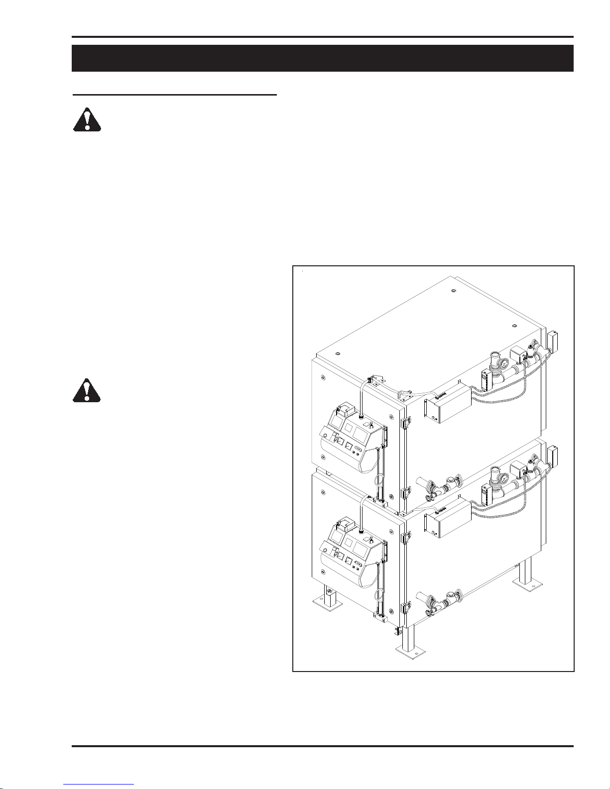
Assembling the Dual-Stacked Boiler
WARNING: Use extreme caution when moving and lifting one of the CTB's (with a forklift)
into place on the support stand. One CTB can weigh up to 907 Kg (Weight of CB-500 with water).
Clean Burn recommends placing safety blocking underneath the unit until it is properly installed and secured on
the support stand. Failure to follow these basic safety guidelines may result in serious personal injury
and/or damage to the unit.
1. Refer to Figures 3C and 3D. Move the support stand into the approximate position where the dualstacked boiler is to be installed, and place blocks (approximately 10 inches high) inside the stand to
provide safety support for the boiler.
NOTE: If the support stand has not
been assembled, refer to Figure 3B.
NOTE: Only use 19 cm (7 1/2") legs
when stacking the boilers. Taller legs
may be unstable.
2. Use a forklift to carefully lift one CTB
into position over top of the support
stand.
WARNING: Secure the boiler to the
forklift prior to lifting to prevent
possible equipment damage or
personal injury.
3. Lower the boiler down onto the safety
blocks positioned inside the support
stand.
4. Insert bolts (provided) into the
keyhole slots in the boiler, and then
lift the stand in position against the
bottom of the boiler.
5. Tighten the bolts to firmly attach the
stand to the bottom of the boiler.
6. Carefully lift the assembled boiler
(with stand) off the safety blocks
and move the unit into place for the
rest of assembly.
NOTE: This boiler will be referred
to as the "bottom" boiler for the
remainder of this procedure.
I88743−B
(Procedure continued on page 3-6)
Figure 3C - Dual-Stacked Boilers
(Completely Assembled)
3-5
Coil Tube Boiler Operator's Manual: Models CB-200-CTB, CB-350-CTB and CB-500-CTB (230 V / 50 Hz)
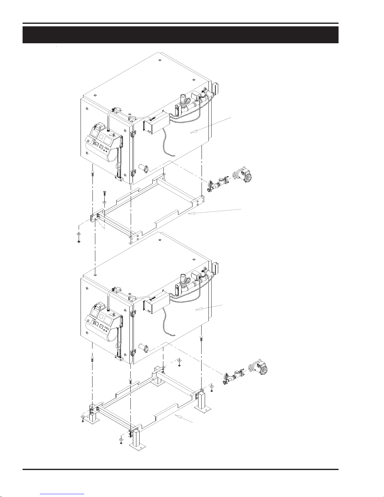
Dual-Stacked Boiler Assembly
"TOP" BOILER
(USER SUPPLIED)
ADAPTOR
BRACKET
"BOTTOM" BOILER
(USER SUPPLIED)
Figure 3D - Dual-Stacked Boiler Assembly Detail
SUPPORT STAND
V
O
M
R
B
E
E
R
E
L
T
I
O
E
X
R
T
B
N
G
I
P
L
U
A
T
O
N
S
I
M
L
L
I88737-C
M
R
F
O
S
N
E
G
L
A
A
F
3-6

Coil Tube Boiler Operator's Manual: Models CB-200-CTB, CB-350-CTB and CB-500-CTB (230 V / 50 Hz)
Dual-Stacked Boiler Assembly
Assembling the Dual-Stacked Boiler (continued)
7. Refer to Figures 3D and 3E. Assemble the adaptor bracket using the 1" x 3/8" bolts provided.
NOTE: The adaptor bracket is installed between the two boilers; it is fastened to the underside of the
"top" boiler unit.
8. If you have not already done so, remove the pre-assembled hardware from the top of the "bottom"
boiler. You will use this hardware to fasten the adaptor bracket.
9. Use a forklift to carefully lift the "top" boiler unit from underneath (see safety warning at the beginning
of this procedure).
10. Attach the adaptor bracket to the bottom of the boiler using the 1" x 3/8" carriage bolts provided.
DO NOT completely tighten the bolts until the two units are assembled together.
NOTE: The notches on the adaptor bracket are designed to fit around standard forklift forks.
11. After the bracket has been attached to the underside of the "top" boiler unit, move the "top" unit
into position over the "bottom" unit.
12. Carefully lower the "top" boiler down onto the "bottom" boiler, watching for alignment of the
bracket holes and the holes in the top of the boiler below.
13. Install the hardware through the lower set of holes in the adaptor bracket into the top of the
"bottom" boiler while checking for proper alignment of the two units. Ensure that ALL hardware
is securely tightened.
Figure 3E - Dual-Stacked Boiler Adaptor Bracket
I88465-A
3-7

Coil Tube Boiler Operator's Manual: Models CB-200-CTB, CB-350-CTB and CB-500-CTB (230 V / 50 Hz)
Assembly for ALL Boilers
Connecting the CTB
Refer to Figures 3A, 3C, and 3D. Connecting the boiler involves three activities:
• Supply Side Connections
• Return Side Connections
• Wiring
NOTE: If you are installing dual-stacked boilers, each boiler must be installed in the same manner
according to the following guidelines for connections/wiring.
Supply Side Connections
• Install the temperature/pressure gauge into the first tee (the 1/2" tapping). Be sure to use
pipe dope on the threads of the gauge. Tighten the gauge into the tee.
• All other components on the supply side are factory installed and pre-wired for operation.
Return Side Connections
Boiler circulator - (user-supplied)
NOTE: Installation instructions are provided for both required and optional components.
• Mount the boiler circulator (user supplied) onto the flanged check valve assembly mounted on the
boiler. Place a gasket between the two flanges and tighten.
• Install the return piping assembly onto the other side of the circulator flange. Place a gasket
between the two flanges and tighten.
Wiring
• For each boiler, connect the wire from the CTB control box to the circulator. Refer to the
CTB wiring diagram in Appendix B as needed. If necessary, excess length may be trimmed
from the circulator wires.
3-8

Coil Tube Boiler Operator's Manual: Models CB-200-CTB, CB-350-CTB and CB-500-CTB (230 V / 50 Hz)
Assembly for ALL Boilers
Installing the Ceramic Sleeve in the Boiler
NOTE: The ceramic target is factory-installed.
1. Refer to Figures 3F and 3G.
2. Swing open the clean-out door on the CTB front to gain access to the combustion chamber.
3. Install the stand for the ceramic sleeve as detailed in Figure 3F. Position the stand on the coils
approximately 3" in from the door opening.
4. After the ceramic sleeve has been installed and positioned properly, close the clean-out door.
5. Tighten the four (4) nuts and washers in a criss-cross pattern until all are snug.
NOTE: The ceramic sleeve needs to seat firmly against the door insulation for proper combustion. Carefully
position the ceramic sleeve on the stand so that it extends out slightly beyond the door opening, so that the door
will push the ceramic sleeve in place as it is closed.
DOOR OPENING
SURFACE
CERAMIC SLEEVE
7.5 cm (3")
CERAMIC STAND
Figure 3F -Positioning of the Ceramic Stand and Ceramic Sleeve
I88463A
3-9

Coil Tube Boiler Operator's Manual: Models CB-200-CTB, CB-350-CTB and CB-500-CTB (230 V / 50 Hz)
Assembly for ALL Boilers
CERAMIC
SLEEVE
I88124-B
CERAMIC
STAND
Figure 3G - Ceramic Stand and Sleeve Installed in the Combustion Chamber
3-10

Coil Tube Boiler Operator's Manual: Models CB-200-CTB, CB-350-CTB and CB-500-CTB (230 V / 50 Hz)
Assembly for ALL Boilers
Checking the Burner Nozzle and Electrodes
NOTE: The burner nozzle is factory installed. Models CB-200-CTB and CB-350-CTB use a Delavan 9-5
nozzle. Model CB-500-CTB uses a 9-28 Delavan nozzle. The nozzle size is indicated on the nozzles as shown
in Figure 3H. Refer also to Appendix A at the back of the manual for additional specifications on the burner
nozzle.
ATTENTION: Check the electrode settings as specified in Figure 3H. The electrode settings must be
correct for your burner to operate properly.
NOZZLE IS STAMPED
9−5 OR −5 ON FLAT
OF NOZZLE HEAD
5 mm
(3/16")
NOZZLE
ELECTRODE
NOZZLE ADAPTER
3mm (1/8") SPARK GAP
OUTLINE OF RETENTION HEAD
3 mm
(1/8")
Figure 3H - Burner Nozzle and Electrode Specifications
NOZZLE TO BE AHEAD OF
RETENTION HEAD BY 3 mm (1/8")
3-11
I88757

Coil Tube Boiler Operator's Manual: Models CB-200-CTB, CB-350-CTB and CB-500-CTB (230 V / 50 Hz)
Assembly for ALL Boilers
Mounting the Burner on the Hinge Bracket
NOTE: The burner may have been mounted on the CTB at the factory. If this is the case, simply check
the clearance between the retention head and the boiler to make sure the burner swings freely into firing
position. If adjustments are necessary, follow the procedure below to adjust the hinge bracket bolts.
1. Remove the nut from the burner mounting flange on the boiler cabinet, and set it aside for later
use.
2. Lift the burner into position and mount it on the hinge bracket of the boiler cabinet.
3. Carefully swing the burner and check the clearance between the retention head and the boiler
throat. There must be at least 3 mm (1/8") clearance, so the retention head is not "bumped" as you
swing the burner into firing position.
If the retention head "bumps" the boiler throat, adjust the hinge bracket bolts as follows:
• While supporting the burner, slightly loosen the two (2) hinge bracket bolts.
• Carefully re-position the burner so it swings freely into its firing position.
• With the burner in its firing position, re-tighten the hinge bracket bolts.
Installing the Connector Block on the CTB Door
1. Refer to Figure 3I on the next page.
2. Use the two (2) bolts to install the aluminum connector block onto the CTB cabinet.
3. Remove and discard the red caps and plugs from the fittings and ports on the connector block.
DO NOT allow any dirt/debris to enter these components during CTB assembly.
ATTENTION: The connector block includes an accumulator. The accumulator functions like a shock
absorber on the oil line to prevent pressure buildup and protect vital burner components. It is important
that the connector block is installed as shown so that the accumulator is in a vertical position to prevent
sediment from settling in the accumulator. Never operate your CTB without the connector block and
accumulator properly installed on the boiler, or damage may occur to vital burner components.
ATTENTION: DO NOT use teflon tape or teflon pipe dope products on any fittings; teflon residue will
plug vital burner components. Non-hardening pipe dope compounds are recommended.
3-12

Coil Tube Boiler Operator's Manual: Models CB-200-CTB, CB-350-CTB and CB-500-CTB (230 V / 50 Hz)
Assembly for ALL Boilers
Installing the Oil Line Tubing
OIL LINE
NOTE: DO NOT disassemble the compression
fitting from the swivel fitting. To prevent leaks, the
NPT threads of the compression fitting have been
sealed with hydraulic sealant during assembly of the
fittings at the factory.
1. Remove and discard the outer red protective
caps from the oil line tubing.
2. Loosely install the oil line tubing into the oil
line fitting on the burner.
3. Use a wrench to slightly rotate the oil line
fitting on the burner counterclockwise so the
tubing lines up with the swivel assembly.
Slightly bend the tubing as shown in Figure
3I, if required, to "line up" the oil line.
4. Make sure that the curl in the oil line is
positioned as shown in Figure 3I so that the
burner can swing open correctly.
5. Install the oil line tubing and tighten the nuts
on the compression fittings. DO NOT
overtighten these fittings to avoid damaging
the ferrules.
CONNECTOR BLOCK
FRONT VIEW OF BOILER
OIL FITTING
ON BURNER
AIR OIL
OIL LINE FITTING
ON BURNER LINED
UP WITH OIL LINE
OIL LINE
NOTE: You may also check the positioning of the
oil line according to Figure 3J on the next page which
provides a larger front view of the connector block
assembly.
SWIVEL
ASSEMBLY
CONNECTOR
BLOCK
SIDE VIEW OF BOILER
SHOWING OIL LINE INSTALLED
Figure 3I - Installation of
Connector Block and Oil Line
I88738A
3-13

Coil Tube Boiler Operator's Manual: Models CB-200-CTB, CB-350-CTB and CB-500-CTB (230 V / 50 Hz)
Assembly for ALL Boilers
AIR LINE FITTING
ON BURNER
OIL LINE FITTING
ON BURNER
AIR LINE
OIL LINE
AIR OIL
I88980
Figure 3J - Installation of Connector Block, Oil Line and Air Line (Front View)
Installing the Air Line Tubing
1. Remove and discard the outer red protective caps from the air
line tubing.
2. Refer to Figure 3J. Push the air line tubing into the fitting
on the connector block until the tubing bottoms out in the fitting.
3. Repeat this procedure to connect the air line tubing to the
air line fitting on the side of the burner.
Locking the Burner into Firing Position
1. Swing the burner into firing position.
2. Install and tighten the lock nut on the mounting plate bolt
to secure the burner in its firing position.
3. Plug the burner electrical cable into the receptacle on the top of
the burner housing.
4. Tighten the locking ring to secure the electrical cable.
COMPRESSION /
SWIVEL FITTING
CONNECTOR BLOCK
INSTALLED ON BOILER
PLUG ON CAM
LOCK CABLE
SLOT IN PLUG
MUST ALIGN WITH
SLOT IN
RECEPTACLE
RECEPTACLE ON
TOP OF BURNER
NOTE: Be sure to properly align the plug when plugging it into the
receptacle. See Fig 3K.
I88354A
Figure 3K - Detail of Burner
Electric Receptacle
3-14

Coil Tube Boiler Operator's Manual: Models CB-200-CTB, CB-350-CTB and CB-500-CTB (230 V / 50 Hz)
SECTION 4: COIL TUBE BOILER INSTALLATION
Understanding Installation
Installing your Clean Burn Coil Tube Boiler (CTB) is a multi-step process which includes:
(1) Oil Tank Installation Specifications
(2) Installing the Metering Pump*
(3) Connecting Water to the CTB
(4) Installing the Oil Lines
(5) Installing the Compressed Air Line
(6) Wiring the CTB and Pump
(7) Installing the Stack
(8) Inspecting the Installation
*NOTE: This manual provides information for the installation of a metering pump with the CTB. If you
ordered a J-pump, please also refer to the separate J-Pump Installation Manual included with your
shipment.
Clean Burn recommends that you review all procedures before beginning installation, paying careful attention to
safety information statements. Figures 4A / 4B provide a general overview of a typical
coil tube boiler installation and should be reviewed closely before proceeding.
WARNING: Improper installation can adversely affect the proper, safe operation of your CTB. It is
critical that your boiler installer reads and follows the instructions provided in this manual. Access to the
boiler must be restricted; only trained, qualified personnel should be permitted to perform installation and
operation procedures.
Important Safety Guidelines for Safe Installation
General installation of the appliance shall be in accordance with the manufacturer's literature, in addition to
complying with the following:
BS5410 Code of Practice for Oil Firing
1997: Installation up to 45 KW output capacity for space heating and hot water supply
purposes.
1998: Installation of 44 KW and above capacity for space heating, hot water and steam
supply purposes.
1978: Installation for furnaces, kilns, ovens and other industrial purposes.
The Building Regulations:
England and Wales: Approved Document J: Heat Producing Appliances (1991).
Scotland: Technical standards for compliance with the Building Standard (Scotland) Regulations
1990, Part F: Heat Producing Installations and Storage of Liquid and Gaseous Fuels.
Northern Ireland: The Building Regulations (Northern Ireland) 1990. Technical Booklet L -
Heat Producing Appliances, July 1991.
Republic of Ireland: The Building Regulations of Ireland 1997, Part J: Heat Producing
Appliances.
Isle of Man, Jersey and Guernsey: The Building Bylaws - BS 7671: 1992 IEE Wiring
Regulations 16th Edition.
4-1

Coil Tube Boiler Operator's Manual: Models CB-200-CTB, CB-350-CTB and CB-500-CTB (230 V / 50 Hz)
Important Safety Guidelines for Safe Installation (continued)
The Environmental Protection Act 1990, Part 1: Processes prescribed for air pollution control by local
enforcing authorities PG1/1 (95).
Secretary of State's Guidance: Waste Oil Burners, less than 0.4 MW net rated thermal input.
November 1995 (Appendix A of OFTEC OFSA 103).
OFTEC Guidelines: Document OFG100 for externally serviced oil fired appliances.
Important Notes to the Electrician
WARNING: Electrical installation of the boiler is to be performed only by qualified personnel
(i.e. licensed electrician/engineer). Improper electrical installation can adversely affect the proper, safe
operation of the boiler and may cause serious personal injury/death.
WARNING: Before completing any boiler wiring, refer to the wiring diagrams in Appendix B
at the back of the manual. Carefully review the wiring assignments and colors, noting that the Clean
Burn wire colors may not be "standard" or familiar.
WARNING: High earth leakage current / earth connection is essential and must be established
before connecting the main power supply.
WARNING: Low voltage terminals are only protected by basic insulation--caution is required.
CAUTION: Use only approved wire conduit and connectors when wiring the Clean Burn
boiler. An emergency stop device (i.e. "panic button") must be installed at ground level in the mains
cable to the boiler to ensure the safety of boiler operators and service personnel. The external disconnect
device must employ a contact separation of 3mm in all poles; the external breaker must be an approved type.
CAUTION: The mains cable must be introduced into the control box using conduit connectors
which provide adequate strain relief. The mains cable installation must be accomplished using suitably
rated and approved wiring (BASEC or HAR) or appropriate current-carrying capacity. The wires should have
a minimum rating of 90 oC (194 oF).
NOTE: According to Clause 4A of 61000-3-11 (International Electrical Standard), the user must determine,
in consultation with the supply authority, that the boiler is connected only to a supply with an impedance of
3.773 x 10⁻³ + 2.358 x 10⁻³ or less.
4-2
Coil Tube Boiler Operator's Manual: Models CB-200-CTB, CB-350-CTB and CB-500-CTB (230 V / 50 Hz)
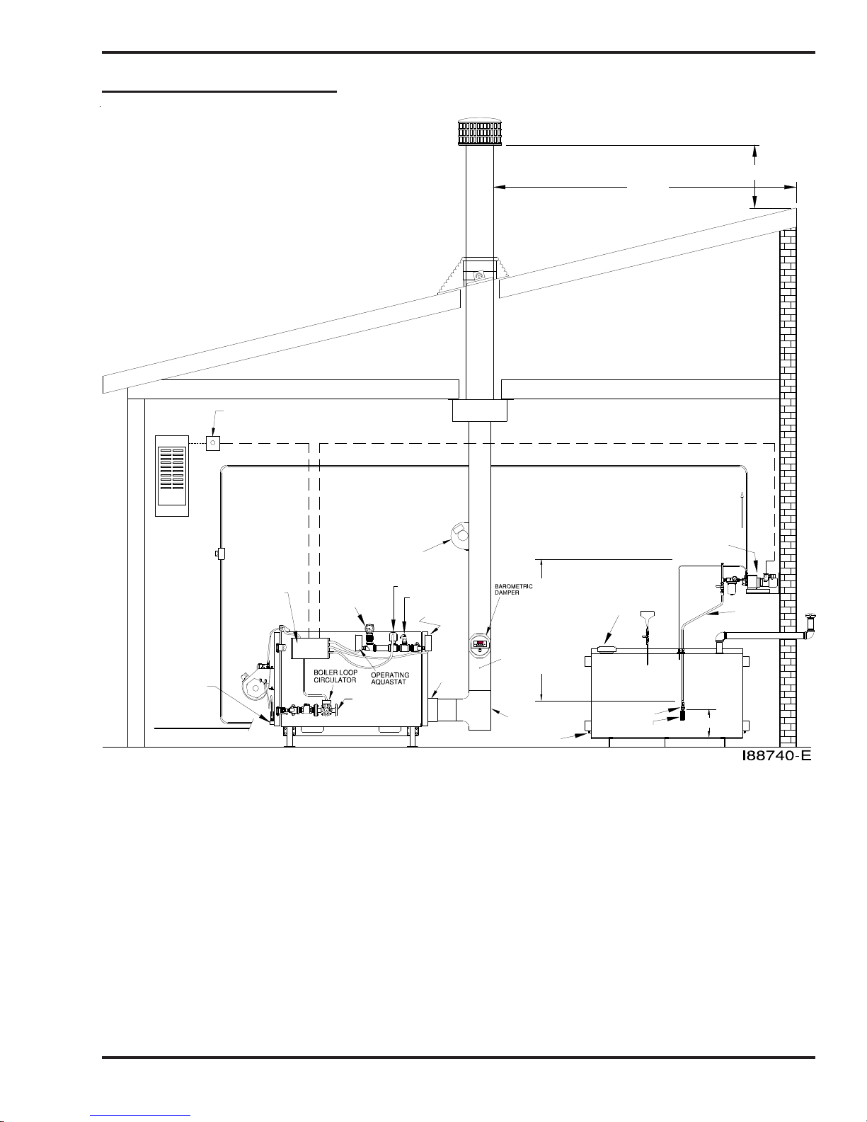
Typical Installation Diagrams
"CLASS A" STACK CAP
WATERTIGHT ROOF FLASHING
"DEKTITE" FLASHING OR
EQUIVALENT
ELECTRICAL THERMO CUT−OFF (OPTIONAL)
DEDICATED ELECTRICAL CIRCUIT
220 VOLT 15 AMP
(OPTIONAL)
OIL THERMO
CUT−OFF
20 cm (8") SINGLE
WALL STACK
MIN. 24 GAUGE
DRAFT
INDUCER
3 m (10’)
"CLASS A" STACK
1150 °C (2100 °F) ALL FUEL STACK
INSULATED STACK WITH A
STAINLESS STEEL LINER
"CLASS A" KI T FOR INSTALLING
"CLASS A" ST ACK THROUGH CEILING
PRESSURE OIL LINE INSTALLED
TO CONNECTOR BLOCK ON BOILER
90 cm (3’)
OIL PUMP ELECTRICAL CIRCUIT
METERING
PUMP
OIL FLOW
AIR & OIL
CONNECTIONS
AT CON NECTOR
BLOCK ON BOILER
COMPRESSED AIR LINE
CONTROL BOX
(ELECTRICAL
CONNECTION)
TEMP/PRESSURE
GAUGE
RETURN
FLOW SWITCH
RELIEF VALVE
HIGH LIMIT
W/RESET
FLUE
COLLAR
20 cm DIA.
(8")
6 mm (1/4")
HOLE FOR
CHECKING
O
R
E
M
DRAFT AT
DRAFT
L
E
S
S
BREACH
MAXIMUM 183 cm (6 FT)
THE PUMP MAY BE DECREASE
CAUTION: DO NOT EXCEED 183 cm (6 FT)
NOT PRIME AND/OR THE FLOW RATE FROM
VERTICAL SUCTION LIFT OR THE PUMP WILL
CLEAN−OUT TEE
CLEAN−OUT
Figure 4A - Typical Single Boiler Installation Diagram
EMERGENCY
VENT
945 LITER TANK
(250 GALLONS)
CHECK VALVE
CHECK VALVE SCREEN
30 cm (1 FT)
SUCTION
OIL LINE
VENT
CAP
4-3

Coil Tube Boiler Operator's Manual: Models CB-200-CTB, CB-350-CTB and CB-500-CTB (230 V / 50 Hz)
Typical Installation Diagrams (continued)
"CLASS A" STACK CAP
30 cm (12")
ELECTRICAL THERMO CUT−OFF (OPTIONAL)
DEDICATED ELECTRICAL CIRCUIT
230 VOLT 15 AMP
(OPTIONAL)
OIL THERMO
CUT−OFF
(OPTIONAL)
OIL THERMO
CUT−OFF
AIR AND OIL CONNECTIONS AT
CONNECTOR BLOCK ON BOILERS
COMPRESSED AIR LINE
OIL LINE
COMPRESSED
AIR LINE
230 VOLT 15 AMP
RETURN
1−1/2 NPT
RETURN
1−1/2 NPT
SUPPLY
1−1/2 NPT
SUPPLY
1−1/2 NPT
M
R
O
E
DRAFT
S
L
E
S
CLEAN−OUT TEE
"CLASS A" STACK
1150 °C (2100 °F) ALL FUEL STACK
INSULATED STACK WITH A
STAINLESS STEEL LINER
WATERTIGHT ROOF FLASHING
"DEKTITE" FLASHING OR
EQUIVALENT
"CLASS A" KIT FOR INSTALLING
"CLASS A" STACK THROUGH CEILING
PRESSURE OIL LINES INSTALLED
TO CONNECTOR BLOCKS ON BOILERS
20 cm (8") SINGLE
WALL STACK
MIN. 24 GAUGE
CLEAN−OUT TEE
M
O
R
E
DRAFT
L
E
S
S
BAROMETRIC DAMPER
6mm (1/4") HOLE FOR
CHECKING DRAFT
AT BREACH
1.5m (5 FT) MIN
CLEAN−OUT
EMERGENCY
VENT
3 m (10’)
OIL PUMP ELECTRICAL CIRCUITS
OIL FLOW
OIL FLOW
SUCTION OIL LINE
SUCTION OIL LINE
945 LITER TANK
CHECK VALVE
CHECK VALVE SCREEN
(250 GALLONS)
90 cm (3’)
30 cm (12")
INLETGAUGE
INLET
GAUGE INLET
INLET
CANISTER
FILTER
VENT
CAP
Figure 4B - Typical Dual-Stacked Boiler Installation Diagram
(Two CB-350-CTB Boilers Shown)
4-4

Coil Tube Boiler Operator's Manual: Models CB-200-CTB, CB-350-CTB and CB-500-CTB (230 V / 50 Hz)
Combustion Air Requirements
The CTB system designer/installer must ensure that there is the proper amount of combustion air in the boiler/
mechanical room.
Refer to Figure 4C.
Combustion Air is the required amount of air that the equipment needs to permit the satisfactory
combustion of oil, the proper venting of combustion gases, and to maintain a safe ambient temperature within the
space at safe limits under normal conditions of use.
The following requirements should be followed for proper supply of combustion air:
Units located in confined spaces (units in a boiler room/mechanical room) must have two (2)
permanent openings, one near the top of the enclosure and one near the bottom of the enclosure
as follows:
1. If all of the air is taken directly from the outside of the building by use of vertical ducts each of the two openings must have a total free area of not less than 6.5 cm2 (1 in2) per 4,000
BTU/hr's, or 225 cm2 (35 in2) per gallon of oil, of the total appliance(s) input rating.
2. If all of the air is taken directly from the outside of the building by use of horizontal ducts each of the two openings must have a total free area of not less than 6.5 cm2 (1 in2) per 2,000
BTU/hr's, or 450 cm2 (70 in2) per gallon of oil, of the total appliance(s) input rating.
3. If all of the air is taken directly from inside of the building - each of the two openings must have
a total free area of not less than 6.5 cm2 (1 in2) per 1,000 BTU/hr's, or 900 cm2 (140 in2) per
gallon of oil, of the total appliances(s) input rating.
4-5

Coil Tube Boiler Operator's Manual: Models CB-200-CTB, CB-350-CTB and CB-500-CTB (230 V / 50 Hz)
I88978
ABOVE FLOOR)
(ENDS 1 FOOT
INLET AIR DUCT
VENTILATION LOUVERS
(EACH END OF ATTIC)
AIR
OUTLET
AIR OILOILAIR OILAIR
DRAFT
AIR TAKEN FROM INSIDE THE BUILDING
APPLIANCES LOCATED IN CONFINED SPACES − ALL
OPENING
OUTLET AIR DUCT
INLET AIR DUCT
AIR TAKEN FROM OUTSIDE THE BUILDING
DRAFT
APPLIANCES LOCATED IN CONFINED SPACES − ALL
Figure 4C - Air for combustion and ventilation
OPENING
DRAFT
AIR TAKEN FROM INSIDE THE BUILDING
APPLIANCES LOCATED IN CONFINED SPACES − ALL
4-6

Coil Tube Boiler Operator's Manual: Models CB-200-CTB, CB-350-CTB and CB-500-CTB (230 V / 50 Hz)
Oil Tank Installation Specifications
Ensure that your tank installation adheres to the
following safety guidelines as stated here and in
Section 1 of this manual.
The tank safety label (shown at right) also
summarizes these important specifications for tank
installation and usage. If you do not have a copy of
this label, please contact your Clean Burn dealer for
a copy, which is to be affixed directly to your used
oil supply tank.
• The tank installation must meet all
national and local codes. Consult your
local municipal authorities for more
information as necessary.
• Use a minimum 945 liter (250 gallon) tank.
DO NOT use a drum as a substitute for an
appropriate tank. The tank must be large
enough to allow water, sludge, etc. to settle
out of the used oil.
• The tank must have a manual shut-off
type valve on the side of the tank to allow
the water, sludge, etc. to be drained from
the bottom of the tank.
• All unused openings in the tank must be
plugged or capped off.
• For optimal system functioning, Clean Burn
recommends inside tank installations as
shown in Figures 4A and 4B.
• The tank must be vented to the outside of
the building using iron or steel pipe and
fittings with an approved vent cap.
• Carefully review the oil tank and pump
installation details as shown in Figures 4A,
4B, and 4C, including the metering pump
installation and specifications for the oil
line installation. (Procedures for installing
these components can be found in the
following pages.)
IMPORTANT NOTE: If you are installing an
inside oil tank in the same room as the boiler, you
must allow a 1.5 m (5 foot) minimum clearance
between the tank and the boiler. The oil tank should
be set and installed in position BEFORE the boiler is
installed.
4-7
Coil Tube Boiler Operator's Manual: Models CB-200-CTB, CB-350-CTB and CB-500-CTB (230 V / 50 Hz)
Oil Tank Installation Specifications (continued)
TANK VENT KITS AVAILABLE FROM CLEAN BURN:
CB Part # 70380 − 4" Tank Vent Kit
(2) elbows
(2) 6" nipples
(1) mushroom cap vent
(1) emergency vent
MUSHROOM
CAP VENT
STEEL PIPE
(USER SUPPLIED)
FUNNEL WITH
BALL VALVE
EMERGENCY
VENT
PRESSURE
RELIEF OIL
LINE BACK TO
THE TANK
PRESSURE
LINE
PUMP
SUCTION LINE
ASSEMBLY
CHECK
VALVE
FILTER
SCREEN
CLEAN−OUT
(TANK DRAIN)
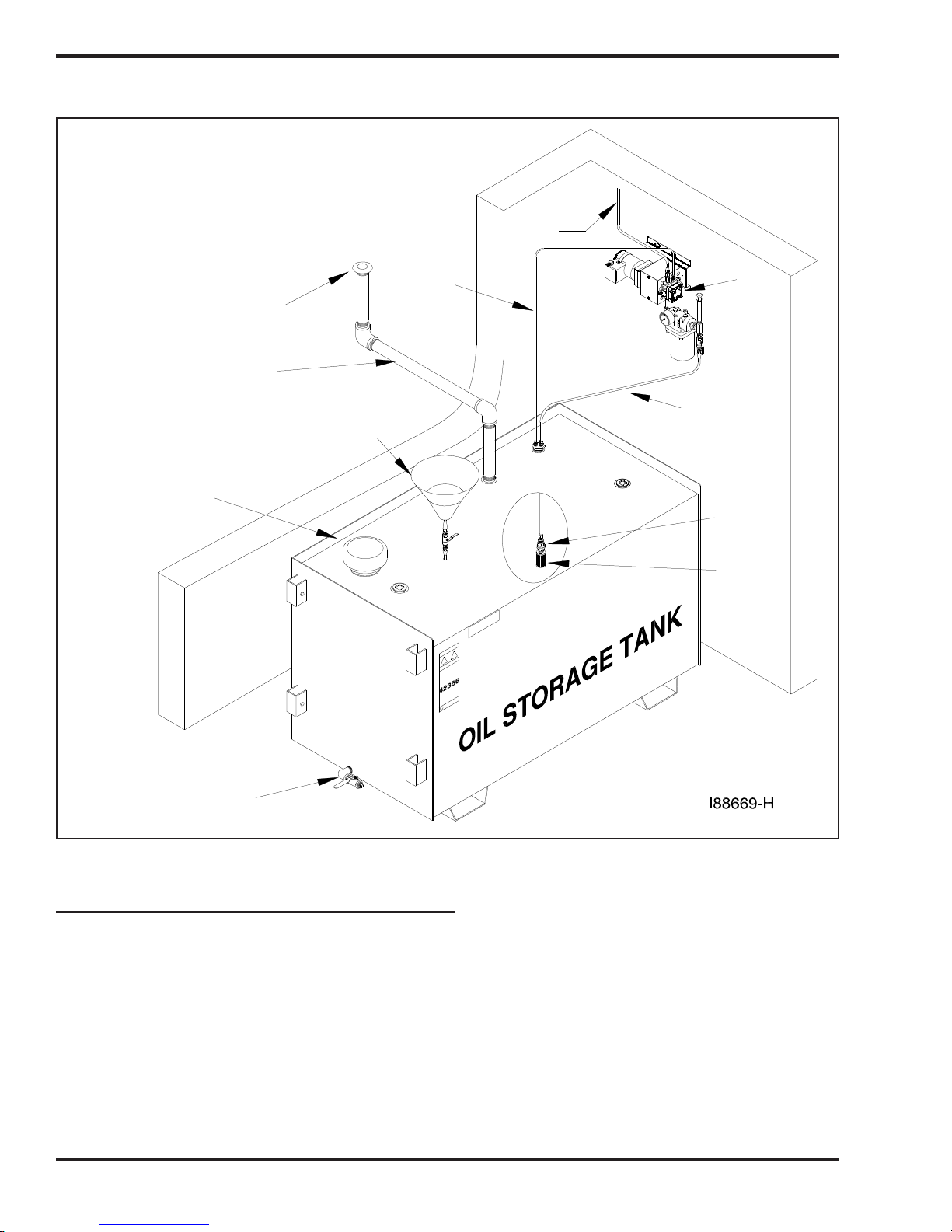
Figure 4D - Typical Metering Pump Installation with Inside Tank
Installing the Tank Vent and Emergency Vent
Some codes require that you install a tank vent (to the outside) and an emergency vent for your tank as shown
in Figure 4D. Tank Vent Kits are available from Clean Burn; contact your local Clean Burn dealer to order.
Be sure to check your local codes for any additional tank installation requirements, and adhere to the following
installation guidelines:
• Install a length of minimum 50 mm (2") steel pipe (user-supplied) terminating outside with a proper
vent cap as shown in Figure 4D. Consult local codes for information and requirements
concerning the proper venting of oil storage tanks.
• Install an emergency vent as shown in Figure 4D. Contact your tank manufacturer for
information concerning the proper emergency vent for your tank.
4-8
Coil Tube Boiler Operator's Manual: Models CB-200-CTB, CB-350-CTB and CB-500-CTB (230 V / 50 Hz)
Installing the Metering Pump
Preparing for Installation
Before starting installation of the metering pump, review Figures 4E, 4F, and 4G to become familiar with the
metering pump components. You will also need to accomplish the following activities:
• Verify that you have the proper metering pump for your boiler (note the specific gear motor
part numbers shown in Figure 4F).
• Gather all required tools and materials as needed for installation; as indicated in the
following procedures, some materials (e.g. fittings, tubing) are to be user-supplied.
• Standard mounting is vertical mounting on a wall; this pump installation is recommended.
Alternate mounting is horizontal mounting on a bracket. Be sure to carefully follow the
appropriate procedures/diagrams for pump mounting.
• For optimal metering pump functioning, mount the pump at a distance from the oil tank that will
comply with the following requirements:
The suction oil line may NOT exceed 183 cm (6') TOTAL vertical lift AND 122 cm (4')
TOTAL horizontal lift.
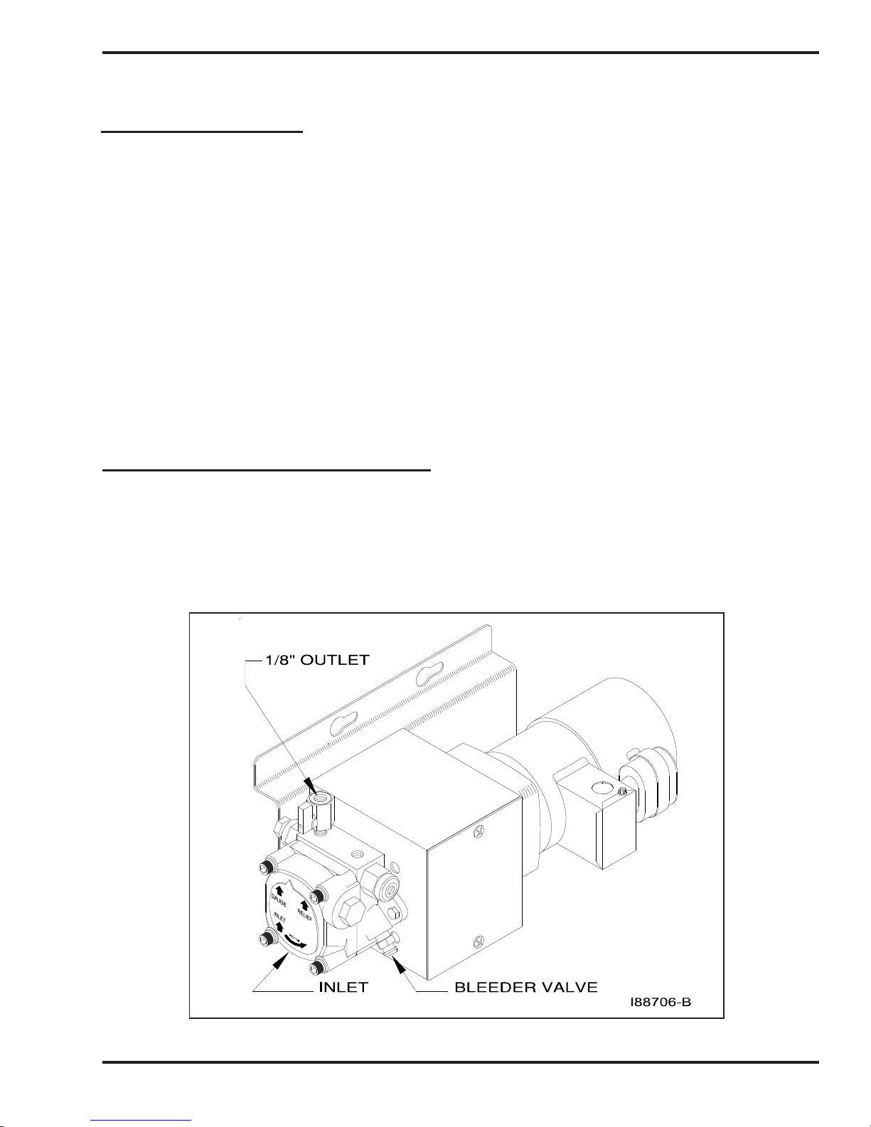
Standard Mounting: Vertical Positioning
1. Refer to Figures 4E, 4F, and 4G. Note that the metering pump is shipped with the pump head already
positioned for the standard vertical wall mounting.
2. Use the appropriate type of bolts and washers (user-supplied) to securely mount the metering pump to
the appropriate wall in your building at a distance from the tank that complies with the suction oil line
requirements.
Figure 4E - Standard (Recommended) Vertical Mounting of the Metering Pump
4-9

Coil Tube Boiler Operator's Manual: Models CB-200-CTB, CB-350-CTB and CB-500-CTB (230 V / 50 Hz)
# PART # DESCRIPTION
2 see c hart GEARMOTOR
3 11322 MOUNT − METER PUMP
4 32037 1/8 NPT X 1/4 TUBE COMPRESSION FITTING
5 N/A 1/4 COPPER OR ALUM. TUBING
6 N/A 3/8 OR 1/2 TUBE FLARE NUT
7 N/A 3/8 OR 1/2 COPPER OR ALUM. TUBING
8 N/A 1/8 M NPT X 3/8 OR 1/2 FLARE
9 32526 MIN I BALL VALVE 1/8 MNPT X 1/8 FNPT
10 32475 METER PUMP
11 32467 1/4" X 3" NIPPLE
12 32210 1/4" STREET ELBOW
13 32336 1/4" X 3/4" BRASS BUSHING
14 32123 VACUUM GAUGE
15 32127 CANISTER FILTER− LENZ
16 32430 1/2" x 3/4" BUSHING, BRASS
17 32446 1/2" X 5" NIPPLE
18 32429 1/2" STREET TEE, BRASS
19 32137 1/2" HEX NIPPLE
20 32142 1/2" BALL VALVE
21 32062 1/4" NPT x 1/4" TUBING FITTING
22 32443 1/4" x 1/2" BUSHING
23 32141 1/2" NPT x 1/2" TUBING FLARE ADAPTER
24 32140 1/2" LONG NUT
25 32139 1/2" NPT x 1/2" TUBING SLIP ADAPTER
26 32442 2" x 1/2" x 1/2" NPT DUPLEX HEX BUSHING
27 32021 3/4" CHECK VALVE
28 32061 3/4" CHECK VALVE SCREEN
29 32445 1/2" PIPE CAP
18
29
16
17
13
10
11
6
5
7
3
4
2
8
9
12
14
21
22
19
20
15
23
24
25
26
24
23
16
Figure 4F - Metering Pump Component Detail
4-10
27
28
CLEAN BURN
MODEL
CB−1500
CB−2500
CB−3500
CB−5000
CB−200−CTB
CB−350−CTB
CB−500−CTB
GEARMOTOR
PART #
33425
33426
33427
33428
33530
33436
33571
I88728−F

Coil Tube Boiler Operator's Manual: Models CB-200-CTB, CB-350-CTB and CB-500-CTB (230 V / 50 Hz)
Alternate Mounting: Horizontal Positioning
ATTENTION: If the metering pump is to be mounted horizontally or on a bracket as shown in
Figure 4G, the pump head must be rotated counterclockwise so that it is aligned in a horizontal position. The
gauge arrow on the pump head must point up, or the pump will not prime.
1. Refer to Figures 4F and 4G.
2. Remove the two pump mounting bolts. The coupling is keyed and does not have set screws.
3. Rotate the pump head 180 degrees to the horizontal position as shown in Figure 4G.
4. Re-install and tighten the two pump mounting bolts.
5. Use the appropriate type of bolts and washers (user-supplied) to securely mount the metering
pump to the mounting bracket, which is to be installed on the appropriate wall in your building at a
distance from the tank that complies with the suction oil line requirements.
RELIEFGAUGE
A2RA−7720
INLET
ROTATION
GAUGE
RELIEF
A2RA−7720
INLET
ROTATION
RECOMMENDED SETUP
PUMP IS MOUNTED
LEFT ON WALL
I88708−B
Figure 4G - Proper Positioning of Metering Pump Head
GAUGE
RELIEF
A2RA−7720
INLET
ROTATION
INLETINLET
ALTERNATE MOUNTING
(NOT RECOMMENDED)
BLEED VALVE IS NOW CLOSE
TO THE WALL MAKING THE
BLEEDING DIFFICULT
GAUGE RELIEF
A2RA−7720
INLET
ROTATION
INLET
NON−STANDARD SETUP
PUMP HEAD HAS BEEN
ROTATED 90° CCW FOR
HORIZONTAL MOUNTING
(THE 1/4" STREET ELBOW AND
1/4" X 3" NIPPLE CHANGE PLACES
IN THE PLUMBING SEQUENCE)
4-11

Coil Tube Boiler Operator's Manual: Models CB-200-CTB, CB-350-CTB and CB-500-CTB (230 V / 50 Hz)
Connecting Water to the Coil Tube Boiler
IMPORTANT NOTE! Detailed information on the installation and operation of the
hydronics system is provided in Section 10 of this manual. The instructions
provided here are abbreviated and serve only to indicate when these procedures
should be performed; consult Section 10 for the detailed version.
1. Connect the desired header supply and return lines to the CTB.
2. Have the water trim installed by a certified hydronics technician. Heat exchangers must be used for
domestic water heater installations.
3. For air separation and elimination, Clean Burn recommends the Enhanced Spiral-Type Air
Separator which can be supplied by your local Clean Burn dealer. Installing an air separator
helps ensure that air is purged from the boiler, which is necessary for optimal startup and
operation of the burner.
4. The relief valve discharge must be piped to within four inches of the floor or to a floor drain.
Be sure to allow for clearance to remove the back panel for servicing.
Filling the Coil Tube Boiler with Water
ATTENTION: It is necessary to fill the CTB with water prior to wiring and turning the CTB ON.
The boiler circulator bearings are water lubricated and should not be allowed to operate dry. Filling the
CTB with water provides immediate lubrication of the bearings. Purging air from the water is also
critical; doing so enables proper startup of the burner.
1. Fill the CTB with clean tap water.
ATTENTION: To prevent damage to the CTB, DO NOT fill the boiler with water when the
boiler is hot.
2. The pressure gauge should read 0.8 bar (12 psig). If a different operating pressure is needed, contact
the Clean Burn Service Department for additional instructions.)
3. Refer to Section 10, The CTB Hydronic System, for additional information.
4-12

Coil Tube Boiler Operator's Manual: Models CB-200-CTB, CB-350-CTB and CB-500-CTB (230 V / 50 Hz)
Installing the Suction Oil Line Components
ATTENTION: It is critical that you adhere to the following specifications for suction oil line
installation (oil line from the tank to the pump). If these specifications are not met, the metering pump
will not function correctly and the burner will shut down on reset. The majority of service problems with the
metering pump are caused by leaks at fittings in the suction oil line; these problems are eliminated by ensuring
a 100% airtight suction oil line which slants up to the pump.
• All suction oil line components must be installed as shown in Figures 4A, 4B, and 4F.
Suction line size is 1/2" (12.7 mm) diameter. Proper installation allows the suction oil line to be
filled with used oil during initial priming.
• The suction oil line may NOT exceed 183 cm (6') TOTAL vertical lift AND 122 cm (4')
TOTAL horizontal lift (which equals 6.0” hg maximum operating vacuum). To determine if
your suction oil line will meet this specification for maximum operating vacuum, base the calculation
for your installation on the following equivalents:
30 cm (1') vertical = 0.75” hg (vacuum)
122 cm (4') horizontal = 0.75” hg (vacuum)
NOTE: ALSO ADD 0.75" hg to the final sum to account for every oil filter, shut-off valve, and
check valve on the suction side of the pump assembly.
Sample calculation: 183 cm / 30 vertical cm feet x 0.75" = 4.50" hg AND
122 horizontal cm = 0.75" hg
4.50" hg + 0.75" hg + 0.75" hg = 6.00" hg vacuum
• The metering pump must be installed with a 3/4" check valve and screen at the end of the
suction oil line, or the pump will not maintain its prime.
• Use Permatex #2 non-hardening gasket sealer on every threaded fitting. DO NOT use
teflon tape or teflon pipe dope compounds; the teflon can flake off and cause damage to the
pump head.
• The suction oil line must be 100% airtight for proper system functioning. Use only
high-quality flare fittings for the copper tubing. DO NOT use compression fittings.
DO NOT use any steel pipe unions. DO NOT use sweat copper pipe. These types of fittings
cause air leaks in the suction oil line and will require re-installation.
• The suction oil line must slant up to the pump; any high spots will trap air and will not
allow the pump to prime.
1. Assemble the suction oil line fittings (from the metering pump to the canister filter):
a. Refer to Figure 4F for a detailed look at the metering pump components and fittings.
b. Remove the plug from the 1/4" inlet port of the pump.
c. Install the 1/4" x 3" brass nipple into the 1/4" inlet port on the pump.
d. Install the 1/4" brass street elbow onto the 3" brass nipple; turn the fitting onto the nipple
until it is tight and faces away from the pump mounting plate.
e. Prepare the canister filter for installation:
• Install the 3/4" x 1/4" brass hex bushing into the outlet port of the canister filter.
Check the direction of the arrow for the proper flow.
• Install the 3/4" x 1/2" brass bushing into the inlet port of the canister filter.
4-13

Coil Tube Boiler Operator's Manual: Models CB-200-CTB, CB-350-CTB and CB-500-CTB (230 V / 50 Hz)
Installing the Suction Oil Line Components (continued)
(e.) Prepare the canister filter for installation (continued):
• Remove the plug from one of the 1/8" gauge ports in the canister filter and install the
vacuum gauge. Seal the threads of the gauge with Permatex #2 non-hardening gasket
sealer.
• Install the 1/2" threaded pipe adapter into one side of the 1/2" ball valve.
• Install the 1/2" MPT x 1/2" flare adapter into the other side of the ball valve.
• Install this assembly into one side of the 1/2" brass tee.
• Install the assembled 1/2" tee into the 3/4" x 1/2" brass bushing, which is installed in
the inlet port of the canister filter. Make sure that the 1/2" flare adapter is pointing
down.
• Install the canister filter assembly onto the 1/4" brass street elbow as shown in Figure
4E. The canister filter must be installed with the arrow pointing towards the pump
(direction of oil flow).
• Install the 1/2" x 5" brass nipple into the top side of the 1/2" brass tee assembly.
• Loosely install the 1/2" brass cap onto this nipple. DO NOT tighten the cap at this
time.
2. Install the suction oil line (from the the tank to the canister filter):
a. Refer to Figures 4A, 4B, and/or 4F.
b. Prepare a piece of 1/2" O.D. copper tubing (user-supplied) which will function as the pick-up
line from the tank to the canister filter. This copper tubing must have the following
specifications:
• The tube must be one continuous piece of 1/2" O.D. copper tubing with no kinks
or fittings.
• The tube is to slant up from the tank to the pump with no loops or high points to
trap air.
c. Locate the 2" MPT x 1/2" FPT x 1/2" FPT duplex, slip-thru hex bushing (which will
eventually be installed into one of the 2" openings on the tank). Note that the fitting is
marked "S" for suction and "R" for return.
d. Install the 1/2" MPT x 1/2" slip fitting into the "S" side of the 2" duplex slip-thru hex
bushing.
e. Install the 1/4" MPT x 1/4" compression fitting into the 1/2" x 1/4" brass bushing.
f. Install the 1/2" x 1/4" brass bushing into the "R" side of the 2" duplex slip-thru hex bushing.
g. Measure the height of the oil tank (from the bottom of the tank, NOT the floor) to the 2"
opening that you are going to use for the supply oil line. Deduct 30 cm (12") from this
measurement and transfer this new measurement onto the 1/2" O.D. coppper tubing.
h. Remove the locking nut and ferrel sleeve connector from the 1/2" slip fitting, and slide them
over the copper tubing.
i. Slide the 1/2" O.D. copper tubing through the 1/2" slip fitting, which is installed in the "S"
side of the 2" hex bushing.
j. Install the screen into one side of the 3/4" check valve (making sure the arrow is pointing
away from the screen assembly).
k. Install the 3/4" x 1/2" brass bushing into the 3/4" check valve.
l . Install the 1/2" MPT x 1/2" flare adapter into the 3/4" x 1/2" brass bushing.
4-14

Coil Tube Boiler Operator's Manual: Models CB-200-CTB, CB-350-CTB and CB-500-CTB (230 V / 50 Hz)
Installing the Suction Oil Line Components (continued)
(2.) Install the suction oil line (continued)):
m . Slide the 1/2" flare nut over the end of the 1/2" copper tubing, and flare the end of the tubing.
NOTE: Use a high-quality flaring tool (such as a Ridgid Flaring Tool) to ensure that all
flares are made properly (i.e. so they will be 100% airtight).
n. Install the flared oil line and nut onto the assembled check valve/screen and tighten.
o. Pick up the assembled oil line, and carefully guide the end of the tubing with the check valve
through the 2" tank opening.
p. Apply Permatex #2 non-hardening gasket sealer (or equivalent) to the threads of the 2"
duplex slip-thru tank bushing, and tighten this fitting into the tank.
q. Pull the 1/2" copper tubing back up through the slip fitting until you see the mark that you put
on the tubing earlier. Holding the tubing with one hand, push the ferrel sleeve connector and
locking nut down the tubing, then tighten onto the 1/2" slip fitting. The oil line is now
installed in the correct position off of the bottom of the tank.
r. Carefully bend the oil line up to the canister filter; use a spring bender over the oil line while
bending the tubing to prevent kinks in the oil line. Allowing for the flare nut, cut off the
excess tubing.
s. Install the 1/2" flare nut onto the tubing, and flare the end of the tubing.
t. Install the end of the tubing with the flare nut onto the 1/2" flare adapter (on the ball valve
assembly at the canister filter).
u. Install a vent from the tank to the outside of the building according to code. The tank must
be properly vented to allow air to enter the tank as oil is pumped out and to safely vent fumes
to the outside. See Figures 4A/4B.
v. Install plugs in all other tank openings as required by code.
w. Inspect the installation. For proper suction oil line operation, make sure all components are
installed and positioned as specified in this manual.
4-15

Coil Tube Boiler Operator's Manual: Models CB-200-CTB, CB-350-CTB and CB-500-CTB (230 V / 50 Hz)
Installing the Pressure Relief Oil Line Back to the Tank
ATTENTION: It is critical that you adhere to the following specifications for plumbing the pressure relief
back to the tank.
The metering pump requires the installation of a pressure relief oil line back to the tank that you are pulling oil
from as shown in Figures 4A, 4B, and 4D.
• The pressure relief will open and relieve pressure if there is a restriction in the pressure oil line,
clogged nozzle, etc.
Be sure to use Permatex #2 non-hardening gasket sealer to seal every threaded fitting. DO NOT use teflon
tape or teflon pipe dope compounds.
1. Refer to Figure 4H.
2. Remove the plug from the relief port on top of the metering pump head.
3. Install the 1/8 NPT x 1/4 tube compression fitting in the relief port on top of the metering pump head.
4. Install 1/4" O.D. copper tubing (user-supplied) from the pressure relief port back to the oil tank.
Refer to Figure 4D as needed.
# PART # DESCRIPTION
1 32475 METERING PUMP HEAD (7720)
2 32526 MINI BALL VALVE 1/8 MNPT X 1/8 FNPT
3 INSTALLER SUPPLIED 1/8 MNPT X 3/8 OR 1/2 FLARE
4 INSTALLER SUPPLIED 3/8 OR 1/2 COPPER OR ALUM. TUBING
5 INSTALLER SUPPLIED 3/8 OR 1/2 TUBE FLARE NUT
6 INSTALLER SUPPLIED 1/4 COPPER OR ALUM. TUBING
7 32037 1/8 MNPT X 1/4 TUBE COMP. FITTING
5
6
4
7
3
2
1
Figure 4H - Pressure Relief Oil Line Back to the Tank
4-16

Coil Tube Boiler Operator's Manual: Models CB-200-CTB, CB-350-CTB and CB-500-CTB (230 V / 50 Hz)
Installing the Pressure Oil Line Components
ATTENTION: It is critical that you adhere to the following specifications for pressure oil line
installation (oil line from the pump to the boiler); if these specifications are not met, the metering pump will
not function correctly and the burner will shut down on reset.
• The parameters for pressure oil line installation are:
Length of Pressure Line Line Size
Up to 30 meters (100') 9.5 mm (3/8") O.D. copper tubing
(Please note that some installations will allow for a greater pressure line length.
Contact your Authorized Clean Burn Distributor for more information.)
• If possible, the pressure oil line should slant up to the burner with no loops or high points to
trap air.
• Local codes may require the installation of an in-line "Fire-O-Matic" safety valve.
Be sure to check all appropriate codes to ensure compliance.
1. Refer to Figures 4A/4B, and 4H.
2. Make sure you have purchased all the necessary fittings to complete the installation correctly.
3. Install the fittings and components as shown in the related illustrations. Be sure to use Permatex #2
non-hardening gasket sealer to seal every threaded fitting. DO NOT use teflon tape or teflon pipe dope
compounds.
Installing the Compressed Air Line
NOTE: Your air compressor system must supply air pressure to the boiler with the following
requirements: 3.5 bar (50 psi) and water trap or dryer. If you do not have shop air, an optional air
compressor is available. Contact your local Clean Burn dealer for more information.
1. Run a compressed air line from your shop air to the connector block on the boiler. Use minimum 1/4"
O.D. copper tubing or equivalent for the compressed air line.
2. Install an easily accessible shut-off valve in the air line so the burner can be serviced without
shutting off the shop air in your service area.
3. If necessary, install a pressure regulator (additional to the burner air regulator) in the air line, and set it at
3.5 bar (50 psi.)
ATTENTION: DO NOT feed full shop air pressure to the burner or damage to burner
components may occur.
4. Install a water trap or extractor/dryer in the air line with an automatic drain so compressed air
(rather than water) is supplied to the burner.
ATTENTION: Water must not be fed to the burner, or the flame will be extinguished and the
burner will shut down. Be sure to drain water from your compressor tank on a regular basis to
keep water out of the air line.
4-17

Coil Tube Boiler Operator's Manual: Models CB-200-CTB, CB-350-CTB and CB-500-CTB (230 V / 50 Hz)
Wiring the Coil Tube Boiler
WARNING: To avoid electrical shock, make sure that power to the CTB is turned OFF before
connecting any wires. A licensed electrician should install all wiring to your furnace. All wiring must be
in accordance with national and local codes. Properly size all wires and use electrical conduit for all electrical
lines. Specific wiring schematics are provided in Appendix B at the back of this manual. For safe and proper
operation of the boiler,
Wiring your boiler requires the installation of the following lines/circuits:
(1) A dedicated electrical line to the CTB (see IMPORTANT NOTE below)
(2) A pump electrical circuit from the CTB to the oil pump (see IMPORTANT NOTE below)
(3) A separate circuit for the load loop circulator
IMPORTANT NOTE: Separate, dedicated lines/circuits must be wired for each boiler in the dual-stacked
unit.
Wiring to the Coil Tube Boiler
DO NOT alter factory installed wiring.
WARNING: A fuse-protected disconnect must be mounted in a readily accessible location for
the installation of the unit. This device can also be used for a disconnect in case of an emergency.
1. Install a dedicated electrical circuit to the electrical junction box on the CTB. Note that a
dual-stacked boiler will require two circuits.
CAUTION: DO NOT tie into an existing circuit, or electrical overload may occur.
2. Wire the CTB according to the Wiring Schematic in Appendix B. Ensure that the ground wire is
attached to the GREEN ground screw on the boiler junction box.
3. Check for correct voltage at the CTB and refer to the following chart.
ATTENTION: Incorrect voltage may damage the CTB components.
Total Amp Draw Per Burner & Circulator: 9.4 amps
Load Circulator Ampacity: 2.5 amps (when wired through the CTB control box)
Model Voltage Breaker Qty. & Size* Phase Hertz
CB-200-CTB (single) 230 (1) @ 20 amps Single 50
CB-200-CTB (Dual-Stacked) 230 (2) @ 20 amps Single 50
CB-350-CTB (single) 230 (1) @ 20 amps Single 50
CB-350-CTB (Dual-Stacked) 230 (2) @ 20 amps Single 50
CB-500-CTB (single) 230 (1) @ 20 amps Single 50
*NOTE: Breaker size with optional equipment is 30 amps. When installing any optional equipment (e.g. air
compressor), you must use a 30 amp breaker. Make sure a qualified electrician properly sizes and installs this
electrical circuit. Note that minimum wire size with a 30 amp breaker is 10-gauge copper wire.
CAUTION: DO NOT turn on main power until instructed to do so.
4-18

Coil Tube Boiler Operator's Manual: Models CB-200-CTB, CB-350-CTB and CB-500-CTB (230 V / 50 Hz)
Wiring to the Metering Pump
WARNING: DO NOT wire the oil pump directly into your building's electrical system. The oil pump
must be activated (receive power from) the burner via the pump electrical circuit. DO NOT wire the
pump directly to a wall outlet so that it runs continuously; this will seriously damage your metering pump and/or
boiler and may result in a fire or explosion hazard.
1. Install the oil pump electrical circuit from the CTB to the oil pump location using approved electrical
conduit (refer to Figures 4A/4B).
2. Wire the oil pump circuit according to the wiring schematic provided (Appendix B).
Wiring the Load Loop Circulator
NOTE: To reduce the amount of cold water returned to the boiler (and to protect the boiler from
thermal shock), an optional circulator aquastat can be supplied by your Clean Burn Dealer.
1. Refer to the related information and illustrations in Section 10 and the CTB Wiring Diagram in
Appendix B to locate and understand the wiring for the load loop circulator.
2. The cold water return in your CTB system installation should not be below 60 oC (140 oF).
NOTE: For installations where cold water return is a risk, Clean Burn recommends installation
of a blending loop. If a blending loop is installed in your CTB system, the load loop circulator
should be wired separately from the CTB control box. Refer to Section 10 for additional
information.
4-19

Coil Tube Boiler Operator's Manual: Models CB-200-CTB, CB-350-CTB and CB-500-CTB (230 V / 50 Hz)
Installing the Stack
WARNING: Inappropriate stack materials or improper stack design/installation can adversely
affect the proper, safe operation of your coil tube boiler.
Stack designs are generally classified as follows:
(1) "Class A" stack through the ceiling of the building
(2) "Class A" stack through the sidewall and up the side of the building
Stack Design and Specifications
ATTENTION: The stack design must be single and dedicated for each unit (boiler) according to the
following specifications. Failure to adhere to this rule may result in less than optimal system performance.
Figure 4H illustrates the through-the-ceiling stack design for a single boiler; this stack design is
preferable and is more commonly used. Refer to Figure 4I for the dual-stacked boiler stack design. When
designing your stack, adhere to the following specifications:
• Models CB-200-CTB and CB-350-CTB require 20 cm (8" I.D.) stack components.
• Model CB-500-CTB requires 25 cm (10" I.D.) stack components.
• Dual-stacked units require two (2) stack runs as single stacks.
• Ensure that the vertical stack height is at least 3m (10') PLUS 45 cm (1.5') for every fitting.
(e.g. 45 degree, 90 degree, or T) in the stack run. If needed, increase the vertical length of the
stack or install a draft inducer to obtain -.02" W.C. draft over fire. (Section 8 contains details on
adjusting the draft.)
• Keep the horizontal stack run as short as possible; slant it upward at a minimum of 6 mm (1/4")
per 30 cm (12") of run.
• Keep the stack design simple. Complicated stacks (with long runs and many turns) reduce
draft and result in poor burner performance. Your stack may include only one 90 degree
turn. All other stack turns must be at 45 degrees or less to ensure optimal draft and burner
performance.
NOTE: If you plan to use an existing masonry chimney, the chimney must be lined and be located inside the
building. Exterior masonry chimneys chill the stack gases and result in poor draft and poor burner performance.
ATTENTION: If you have an exhaust fan(s) in your shop, it is critical that you have adequate
make up air (source of fresh air to replace the stale air exhausted by the fan). When an exhaust fan is
run without adequate make up air, the resulting vacuum in the building will draw combustion products back into
the burner. This back draft causes poor burner performance and may damage vital burner components. Refer
to Section 8 in this manual for additional information concerning exhaust fans and proper make up air.
Stack components should be installed in the following order:
(1) Inside stack (the stack components from the coil tube boiler breach to within 457 mm / 18" of the
ceiling, roof, or sidewall of your building)
(2) Barometric damper(s)
(3) "Class A" stack penetration through the ceiling, roof, or sidewall
(4) "Class A" stack on the exterior of the building
(5) "Class A" stack cap
4-20

Coil Tube Boiler Operator's Manual: Models CB-200-CTB, CB-350-CTB and CB-500-CTB (230 V / 50 Hz)
"CLASS A" STACK CAP
NON−RESTRICTIVE TYPE TO ALLOW
FREE FLOW OF THE STACK GASES
THE LAST STACK SECTION SHALL EXTEND
AT LEAST 90 cm (3’) HIGHER THAN
ANY RIDGE, PARAPET WALL OR ROOF
STRUCTURE WITHIN 3 m (10’) OF IT
3 m (10’)
"CLASS A" KIT FOR INSTALLING
"CLASS A" STACK THROUGH CEILING
DRAFT
INDUCER
BAROMETRIC DAMPER
90 cm (3’)
WATERTIGHT
ROOF
FLASHING
"DEKTITE" OR
EQUIVALENT
3m (10’) MINIMUM VERTICAL
STACK HEIGHT OR EQUIVALENT
DRAFT SYSTEM TO MAINTAIN
−.02 W.C. DRAFT OVER FIRE
O
R
E
M
DRAFT
L
E
S
S
"CLASS A" INSULATED STACK
TRIPLE WALL ALL FUEL
STACK WITH A STAINLESS
STEEL LINER
20 cm (8") MINIMUM
SINGLE WALL STACK
MIN. 24 GAUGE
GALVANIZED
Figure 4H - Installation of "Class A" Stack Through Roof/Ceiling (Single Boiler)
I88742−C
4-21

Coil Tube Boiler Operator's Manual: Models CB-200-CTB, CB-350-CTB and CB-500-CTB (230 V / 50 Hz)
Installing the Stack (continued)
DAMPER
20 cm (8")
STACK PIPE
82 cm (32 1/4") BETWEEN
CENTERS (CB−200−CTB)
94 cm (37 1/8") BETWEEN
CENTERS (CB−350−CTB)
20 cm (8")
STACK PIPE
25 cm (10")
BETWEEN CENTERS
I88744−C
Figure 4I - Detail of Dual-Stacked Boiler Stack Installation
Installing the Interior Stack
CAUTION: Single wall stack components may be used only for those portions of the stack
which are located inside your building and away from any fire/burn hazards.
1. The stack can be installed from either side of the smoke hood breach. Install the 20 cm (8") smoke
cap onto the unused smoke hood breach ring assembly.
2. Install a piece of the single-wall 24-gauge galvanized stack (minimum 45 cm (18") in length) onto the
smoke hood breach.
3. Install an elbow or clean-out tee (with a smoke cap installed in the bottom) onto the extension
piece from the boiler smoke hood breach.
4. Install a smoke pipe tee onto this elbow or clean-out tee (for the installation of the barometric
damper).
ATTENTION: Avoid additional 90-degree turns in the stack. Each additional 90-degree turn
slows down stack gases, creates back-pressure, and results in repeated burner shutdown and
unnecessary service calls. All other turns in the stack should be at a 45-degree (or smaller)
angle.
4-22

Coil Tube Boiler Operator's Manual: Models CB-200-CTB, CB-350-CTB and CB-500-CTB (230 V / 50 Hz)
Installing the Barometric Damper(s)
1. Refer to Figure 4J. Install a single wall tee (min. 24 gauge) on the first straight vertical or
horizontal stack section within 1 meter (40 inches) of the CTB breach.
NOTE: This tee is required to support the barometric damper. You must purchase this tee when
you purchase your stack materials (8" single wall tee - CB#70174).
ATTENTION: For Dual-Stacked CTB Units Only - You are required by code to install two
dampers (provided) - one for each boiler. DO NOT attempt to substitute other types of
dampers--they will not allow the unit to function properly and may void your warranty.
2. Install the barometric damper in the opening of the tee. Use a small spirit level to make sure that
it is properly level.
3. Install two self-tapping screws as shown in Figure 4J (i.e. one on each side of the barometric
damper) to hold the damper in place. DO NOT install a screw at the bottom of the barometric
damper, or the flapper of the damper will not operate correctly.
NOTE: Specifications for adjusting the barometric damper for proper draft overfire are provided in
Section 8 of this manual.
9" CLEAN BURN BAROMETRIC
DAMPER WITH ADAPTOR IN
10" SINGLE WALL TEE
2
1
(FOR CB-500-CTB)
INSTALLED IN SINGLE WALL TEE
1
ADJUST THIS WEIGHT TO
OBTAIN PROPER DRAFT
2
111
No
ADJUST THIS WEIGHT TO
OBTAIN PROPER DRAFT
QTY
31198
31197
PART #
I88547
DAMPER PIPE ADAPTOR
9" BAROMETRIC DAMPER
DESCRIPTION
I885398" CLEAN BURN BAROMETRIC DAMPER
(FOR CB-200-CTB and CB-350-CTB)
Figure 4J - Installation of Barometric Damper
4-23
No QTY PART #
8" BAROMETRIC DAMPER3117011
DESCRIPTION
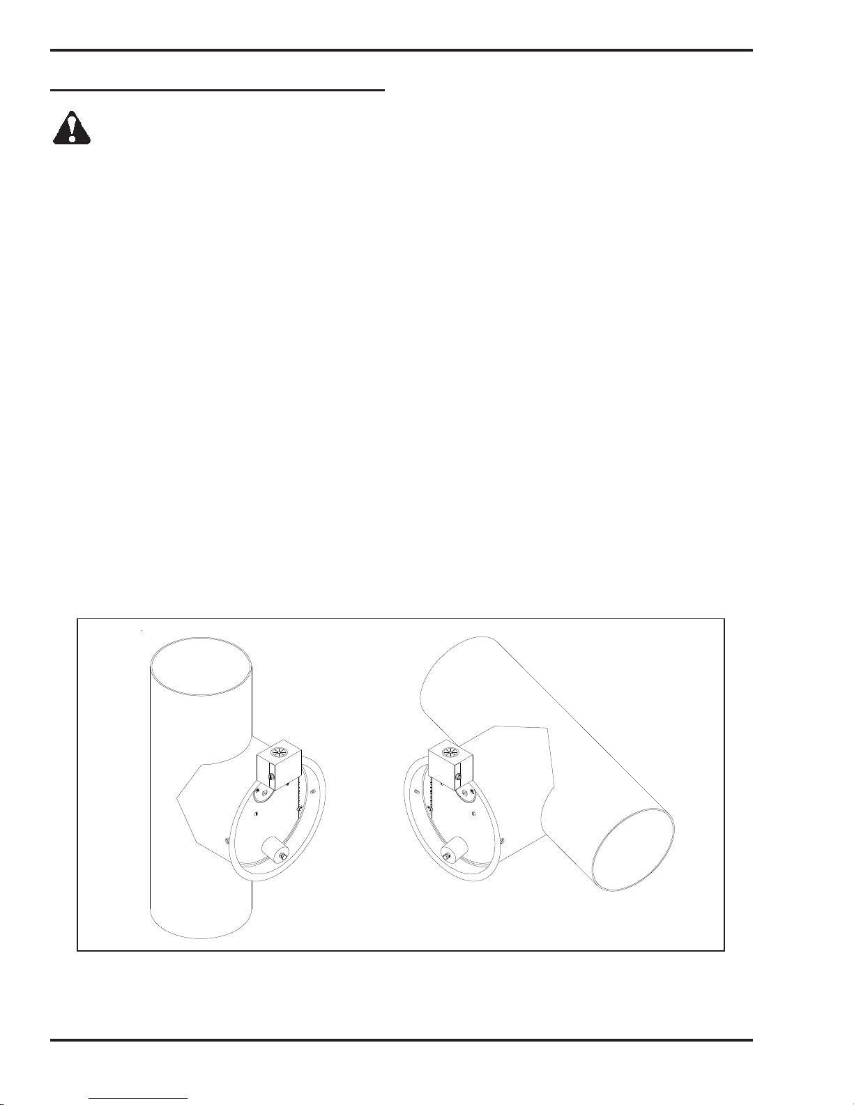
Coil Tube Boiler Operator's Manual: Models CB-200-CTB, CB-350-CTB and CB-500-CTB (230 V / 50 Hz)
Installing the Optional Stack Safety Switch
CAUTION: For your safety and the safe operation of your heating equipment, the stack switch must
be installed by a qualified installer in accordance with the installation instructions provided here. Wiring
must be accomplished in accordance with all applicable codes. Failure to adhere to these safety
recommendations may result in serious personal injury and/or equipment damage.
1. Follow the instructions in the Operator’s Manual, Section 4 to install a proper stack, including the
barometric damper which must be installed within 1 meter (40 inches) of the breach.
NOTE: The barometric damper must be installed so that it is level and the flapper moves freely.
2. Ensure that main power to the heating equipment is turned OFF.
3. Position the stack safety switch over the lip of the barometric damper as shown in Figure 4K.
4. Drill a pilot hole for the mounting screw, and mount the stack safety switch using the mounting
screw supplied with the switch.
NOTE: The mounting screw must not interfere with the free movement of the flapper on the barometric
damper.
5. Install the wall thermostat according to the instructions provided in the Operator’s Manual, Section 4.
Wire the wall thermostat and stack safety switch in series as shown in Figure 4L. Install the wire so that
it is secured away from any hot surfaces.
NOTE: If a 24V thermostat is not used to activate the boiler, the stack safety switch is connected
directly to the landings on top of the control box. Refer to Appendix B for the control box wiring
diagram.
6. When the heating equipment installation is completed, follow the instructions in the Operator’s
Manual, Sections 5 and 6 to prime the pump and start/adjust the burner.
7. Follow instructions in the Operator’s Manual, Section 8 to check the draft; this is crucial for the
proper, safe operation of the heating equipment.
Figure 4K - Stack Safety Switch Installed on the Bar ometric Damper
I88964
4-24
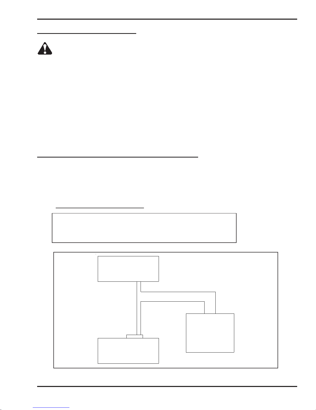
Coil Tube Boiler Operator's Manual: Models CB-200-CTB, CB-350-CTB and CB-500-CTB (230 V / 50 Hz)
Resetting the Stack Safety Switch
WARNING: BURN HAZARD! To prevent serious personal injury, be sure to allow ample time, at
least 30 minutes, for the stack, barometric damper, and switch to cool down before attempting to
access and service these components. It is crucial to identify the cause of the stack obstruction (e.g. heavy
snowfall) and correct it before resetting the stack safety switch and re-starting the burner. DO NOT operate
the heating equipment with an obstructed stack; failure to correct an obstructed stack may result in fire,
explosion, and/or burn hazards causing serious personal injury or death.
NOTE: In locations where heavy snowfall occurs, it is critical that the stack remain unobstructed by snow.
For safe heating equipment operation, be sure to keep the area surrounding the stack clear of snow.
1. Before resetting the stack safety switch, check the stack to make sure it is clear of any obstructions.
2. Remove the cover from the stack safety switch, and push the small button in the middle of the switch.
3. Pushing the stack safety switch reset button will re-establish the thermostat circuit, and the burner will
start (assuming the wall thermostat is calling for heat).
Understanding the Function of the Stack Safety Switch
The Stack Safety Switch monitors the temperature at the barometric damper on the stack and is designed to
detect the obstruction of the free flow of stack gases from the heating equipment and shut down the burner.
Obstruction of the stack results in the “spillage” of stack gases from the barometric damper, which heats up the
switch. The switch then opens, disconnecting the thermostat circuit to the burner, and the burner shuts off.
Stack Safety Switch Specifications
Switching Voltage 24 volts
Switch OPEN Temperature 180 oF
Switch Type L180, normally closed, manual reset
WALL
THERMOSTAT
Figure 4L - Stack Safety Switch Wiring Diagram
CONTROL
BOX
STACK
SAFETY
SWITCH
(MOUNTED ON
BAROMETRIC DAMPER)
I88985
4-25

Coil Tube Boiler Operator's Manual: Models CB-200-CTB, CB-350-CTB and CB-500-CTB (230 V / 50 Hz)
Installing the Stack Penetration
WARNING: When running the stack through your ceiling, roof, or sidewall, you must use
"Class A" double-wall insulated all-fuel stack components with a stainless steel liner. DO NOT
run single-wall stack through your ceiling, roof or sidewall. NEVER locate a stack joint inside walls or in a joist
spacer. Ensure proper clearances from combustibles per all applicable codes.
1. Refer to Figure 4H as needed.
2. Follow the installation instructions provided by the stack manufacturer.
Installing the Exterior Stack
ATTENTION: All exterior stack pieces must be "Class A" double-wall insulated all-fuel stack
components with a stainless steel liner.
• DO NOT use Class B Vent/double-wall stack components (i.e. for gas fired appliances only).
• DO NOT use Type L Vent/double-wall stack components (for approved fuel oil appliances
only).
• DO NOT use single-wall stack for your exterior stack. Single-wall exterior stack chills the
stack gases and results in poor draft and poor burner performance.
1. Refer to Figure 4H as needed.
2. Follow the installation instructions provided by the stack manufacturer.
3. Install water-tight roof flashing around the penetration of the exterior stack.
NOTE: Clean Burn recommends the use of "Dektite" roof flashing (or equivalent) which
ensures a water-tight seal when installed properly. Contact your local Clean Burn dealer for
details.
Installing the Stack Cap
NOTE: Proper installation of a "Class A" stack cap ensures the free flow of stack gases which is essential for
optimal burner performance.
1. Refer to Figure 4H as needed. Your stack cap should be classified as: "Class A" non-restrictive,
all-fuel type.
2. Install the stack cap according to the manufacturer's instructions.
Installing the Draft Inducer
ATTENTION: The Field brand draft inducers have been tested for use on Clean Burn Equipment. DO NOT
use other models or brands of draft inducers.
Understanding the Importance of the Draft Inducer
The draft inducer is designed to aid in the removal of the natural draft created by the appliance to vent the
combustion gases to the outside of the building. As the paddle wheel turns, a negative pressure is maintained
within the stack so that the combustion gases can leave the boiler and travel out of the stack. (See Figure 4M.)
Proper sizing, installation, and adjustment of the draft inducer are critical for optimal draft inducer
operation.
4-26

Coil Tube Boiler Operator's Manual: Models CB-200-CTB, CB-350-CTB and CB-500-CTB (230 V / 50 Hz)
Installing the Draft Inducer (continued)
3 m (10’)
90 cm (3’)
3 m (10’) MINIMUM VERTICAL
STACK HEIGHT OR EQUIVALENT
NOTE: INSTALL DRAFT INDUCER IN LAST
SECTION OF VERTICAL STACK TO POSITION
DRAFT INDUCER AWAY FROM FURNACE
BREACH SO THAT THE MOTOR DOES NOT
OVERHEAT. THIS ALSO REDUCES ASH
ACCUMULATION IN THE DRAFT INDUCER.
DO NOT MOUNT THE DRAFT INDUCER IN THE
HORIZONTAL STACK NEAR THE FURNACE
BREACH
(5’ − 8’)
1.5 m − 2.5 m
−.02 W.C. DRAFT
INDUCER
ADJUSTMENT
CHECK FOR
OVER FIRE
DRAFT
DRAFT
PLATE
SERVICEMAN ADJUSTS
BAROMETRIC DAMPER TO
OBTAIN −.02 W.C. DRAFT
R
E
O
M
DRAFT
L
S
S
E
OVERFIRE
AIR
DRAFT SYSTEM TO MAINTAIN
−.02 W.C. DRAFT OVER FIRE
OIL
I88981
Figure 4M - Installation of the Draft Inducer
WARNING: Turn OFF the main power to the boiler before proceeding with the installation of
the draft inducer.
ATTENTION: It is very important to install the draft inducer on a vertical section of stack to isolate the
inducer from excessive heat and ash buildup. Never install the draft inducer on a horizontal section of stack
close to the breach where heat and ash will damage the inducer motor.
4-27

Coil Tube Boiler Operator's Manual: Models CB-200-CTB, CB-350-CTB and CB-500-CTB (230 V / 50 Hz)
Installing the Draft Inducer (continued)
1. Refer to Figure 4M. Follow the instructions included with the draft inducer to mount the draft
inducer on the section of single-wall vertical stack.
2. Position the draft plate all the way out so that it does not reduce the draft produced by the draft
inducer. You will adjust the draft plate later as part of Adjusting the Draft Overfire (Section 8).
Wiring the Draft Inducer for Normal Operation*
*(No exhaust fans in the building)
1. Wire the draft inducer according to the Wiring Diagram in the Burner Control Box and also
provided in Appendix B at the back of this manual.
Installing the Wall Thermostat or Aquastat
IMPORTANT NOTE: A 24V wall thermostat is available separately from Clean Burn (i.e. it is not included
with the CTB). If a 24V thermostat is used to activate the boiler, a qualified technician would need to remove
the jumper from the external four landings on top of the black control box on the side of the boiler and use it to
connect landings 5 and L1 on the internal terminal block. The 24V thermostat is then connected into the
optional stack safety switch landing. Refer to Appendix B for the control box wiring diagram.
Refer to Appendix A in this manual for additional information on remote temperature sensing controls available
from Clean Burn for your CTB system installation.
1. Select a location for the thermostat on an interior wall away from any hot or cold drafts.
2. Remove the top cover from the thermostat by pushing gently on the latch at the top center of the
body. (Hold the thermostat base in one hand, and grasp the body with the other hand; push in
on the latch with your thumb, and pull the cover away from the base.)
ATTENTION: DO NOT use a screwdriver to pry the cover off the base, or damage may occur.
3. Remove the green paper insert and the black plastic battery isolator from the battery section of the
thermostat.
4. Refer to the Burner Wiring Diagram in Appendix B at the back of this manual. Run two wire,
18-gauge (minimum) thermostat cable from the terminals on the back of the thermostat base to the T/T
terminals of the control box on the side of the boiler. DO NOT run the wiring to the primary control!
5. Mount the thermostat base 1.5 meters (60" to 66") from the floor using the hardware provided.
6. Reassemble the thermostat body onto the base. (Align the hinges at the bottom of the cover with
the slots at the bottom of the base, and swing the cover up into place.)
Replacing the Wall Thermostat Batteries
1. Proper battery level is indicated by the room temperature being displayed on the LCD screen.
2. When the battery level becomes low, a battery icon along with the word "REPLACE" will be displayed
in the lower left corner of the LCD screen. Replace the batteries to ensure proper operation, following
the previous instructions on the thermostat disassembly procedure.
3. If the batteries are not replaced, the display will slowly become dim and not display any information.
The thermostat will eventually not function. If this happens, replace the batteries immediately.
4-28

Coil Tube Boiler Operator's Manual: Models CB-200-CTB, CB-350-CTB and CB-500-CTB (230 V / 50 Hz)
Inspecting the Coil Tube Boiler Installation
Following the completion of all installation activities described in this chapter, the CTB should be
inspected by qualified personnel before firing. This ensures that your installation meets all applicable
national and local codes and allows for any deficiencies in the installation to be corrected before CTB
startup. Improper installation will void your warranty.
NOTE: Important! During the inspection, be sure to check the aquastat settings. Initial settings are
listed here:
• Operating Aquastat 82
o
C (180 oF) minimum
• Hi-limit Aquastat (with manual reset) 115 oC (240 oF)
Refer to Section 6 for burner startup and final adjustments of the aquastat.
Any changes to these settings should be made only by a qualified hydronics technician. See Section
10, The CTB Hydronics System, for more information.
4-29

Coil Tube Boiler Operator's Manual: Models CB-200-CTB, CB-350-CTB and CB-500-CTB (230 V / 50 Hz)
4-30

Coil Tube Boiler Operator's Manual: Models CB-200-CTB, CB-350-CTB and CB-500-CTB (230 V / 50 Hz)
SECTION 5: METERING PUMP PRIMING
Understanding Metering Pump Priming
Preparing your Clean Burn boiler for operation begins with priming the metering pump. The procedures in this
section must be performed in sequence without interruption to properly prime the pump.
IMPORTANT NOTE FOR DUAL-STACKED UNITS: The priming procedures will have to be performed for one burner, and then repeated for the other burner (i.e. get one burner running first before attempting
priming of the other burner.)
Required Tools and Materials
The following tools and materials are required for oil pump priming and should be gathered before
starting any procedures:
• 3/8" open-end wrench
• 5/8" open-end wrench
• Rags
• Two containers (minimum 4 liters / one-gallon each)
• Permatex #2 non-hardening gasket sealer
• Adjustable Wrench
• Pipe Wrench
5-1

Coil Tube Boiler Operator's Manual: Models CB-200-CTB, CB-350-CTB and CB-500-CTB (230 V / 50 Hz)
Priming the Metering Pump
ATTENTION: The priming process must be done precisely as described in this procedure to ensure
that all air is thoroughly bled from the system. Failure to bleed all air from the system will result in
repeated burner shutdowns on reset.
1. Refer to Figure 5A.
2. Remove the 1/4" NPT plug from the side of the pump head, and set it aside.
3. Remove the 1/2" brass cap from the 1/2" brass nipple. Place a funnel in the opening. Slowly
pour used oil into the funnel until oil comes out of the side of the pump head; this will fill the
oil line, canister filter, and pump head with oil.
ATTENTION: NEVER run the pump head dry (i.e. without oil in the pump head). Doing so will
severely damage the pump.
4. Apply Permatex #2 non-hardening gasket sealer to the threads of the plug (removed from the
pump head). Re-install the plug and tighten.
5. Apply Permatex #2 non-hardening gasket sealer to the threads of the 1/2" brass nipple. Re-install
the 1/2" brass cap on the brass nipple and tighten.
6. Open the bleeder on the pump two to three (2-3) full turns, and position a container to catch oil
which will flow from the bleeder during pump priming.
7. Close the mini ball valve at the outlet port of the pump head.
ATTENTION: Verify that the relief oil line is installed back to the tank before closing the mini ball
valve. Closing the mini ball valve will cause the internal pump relief valve to open.
Figure 5A - Priming the Metering Pump
5-2

Coil Tube Boiler Operator's Manual: Models CB-200-CTB, CB-350-CTB and CB-500-CTB (230 V / 50 Hz)
Priming the Metering Pump (continued)
8.
Activating the Pump
NOTE: The coil tube boiler features a priming switch which is mounted on the left-hand side of
the electrical junction box on the front of the boiler cabinet. The priming switch has two
positions:
• PRIME (switch is in the UP position / orange indicator light is ON): this is used only
for pump priming. When the switch is in the UP position, the pump circuit is activated for
priming. The pump will continue to run as long as the switch is in this position. The oil
primary control circuit is de-activated so the burner cannot run while the switch is in the UP
position.
• BURNER (switch is in the DOWN position): this is used for normal burner operation.
When the switch is in the DOWN position, the burner controls the operation of the pump.
The pump will only run while the burner is running.
a. Refer to Figure 5B to locate the priming switch.
b. Turn the priming switch to the UP position. The pump should immediately start running.
OIL PUMP
PRIMING SWITCH
PRIMING LIGHT
AIR REGULATOR
OIL GAUGE
AIR GAUGE
COMPRESSED AIR LINE
Figure 5B - Detail of Burner Connections/Components
CONNECTOR BLOCK
OIL LINE
I88746−A
5-3

Coil Tube Boiler Operator's Manual: Models CB-200-CTB, CB-350-CTB and CB-500-CTB (230 V / 50 Hz)
Priming the Metering Pump (continued)
9. Run the pump until a solid stream of oil flows from the pump bleeder. This will bleed all air out
of the suction line, oil filter and pump head.
ATTENTION: For the metering pump to operate correctly, it is very important that the system
is entirely full of oil and all air is bled out. The burner will shut down if there is any air in the
system.
10. Open the mini ball valve at the outlet port of the pump head to allow the pressure oil line to be filled.
11. Close and tighten the bleeder on the pump.
12. Turn the priming switch to the DOWN position so that the pump stops running.
13. Disconnect the pressure oil ine from the burner and position a container to catch oil which will flow from
the pressure oil ine during pump priming.
14. Turn the priming switch to the UP position. The pump should start running immediately .
15. Run the oil pump until the proper flow of oil has been established, and the oil line has been completely
flushed out.
16. Turn the priming switch to the DOWN position so that the pump stops running.
17. Re-connect the oil line to the connector block.
Vacuum Testing the Oil Pump
Vacuum testing the oil pump is a very accurate way to determine the following:
• The condition of the pump -- the ability of the pump to pull a vacuum and suck oil from the tank.
• The condition of the fittings, gaskets and seals from the ball valve to the pump -- these
components must all be airtight to avoid suction leaks.
The following procedure provides instructions for vacuum testing the pump and canister filter on
systems equipped with a ball valve.
ATTENTION: For the pump to pull and hold vacuum, it is critical that all fittings are airtight. If any of
these fittings are loose, the pump may not pull a vacuum or may lose the vacuum rapidly. It is also
critical that all fittings in the suction line, including fittings on the canister filter, are 100% airtight.
1. Follow the instructions to prime the pump (previous procedure).
NOTE: The pump will not pull a vacuum if the pump is dry. There must be oil in the gears of
the pump before the pump can pull a vacuum.
2. With the pump running, open the bleeder two to three full turns, and make sure that oil is flowing
from the bleeder. DO NOT close the bleeder yet.
3. Refer to Figure 5A. Close the ball valve at the inlet to the canister filter. Observe the vacuum gauge.
NOTE: The ball valve must have a stainless steel ball and should be pressure tested by the
manufacturer to ensure that it does not leak. If the ball valve leaks, the vacuum test will not be
accurate.
4. The vacuum should increase within 30 seconds to 15 inches of vacuum. When the vacuum
gauge reads 15 inches of vacuum, first close and tighten the bleeder, then turn the pump off, and close
the mini ball valve at the outlet port of the pump. Observe the vacuum gauge.
NOTE: If the pump will not pull at least 15 inches of vacuum, there is a very serious suction
leak, or the pump is damaged.
5-4

Coil Tube Boiler Operator's Manual: Models CB-200-CTB, CB-350-CTB and CB-500-CTB (230 V / 50 Hz)
Vacuum Testing the Oil Pump (continued)
5. If there are no suction leaks, the system will hold vacuum.
NOTE: It is acceptable for the vacuum to drop one to five inches within one minute as the seal
in the pump seats. The vacuum should then hold steady for 15 minutes.
ATTENTION: If the vacuum drops more than one to five inches within the first minute, there is
one or more leaks somewhere between the pump and the ball valve. Do the following:
• Wipe your finger along the cylinder at the shaft of the pump. If there is oil here, the pump
seal is damaged. Replace the pump.
• Disassemble and clean all the fittings from the pump to the ball valve. Properly seal all
fittings with Permatex #2 non-hardening gasket sealer or equivalent. Check the condition of
the o-ring on the canister filter and tighten the four canister filter bolts in a crisscross pattern.
• Repeat the procedure to vacuum test the system to ensure that the system is air tight.
6. Follow the instructions to prime the metering pump after a vacuum test has been performed.
5-5

Coil Tube Boiler Operator's Manual: Models CB-200-CTB, CB-350-CTB and CB-500-CTB (230 V / 50 Hz)
5-6

Coil Tube Boiler Operator's Manual: Models CB-200-CTB, CB-350-CTB and CB-500-CTB (230 V / 50 Hz)
SECTION 6: STARTING AND ADJUSTING THE BURNER
Understanding Burner Startup and Adjustment
ATTENTION: Before starting the burner, you must fill the coil tube boiler with water. Refer to
Section 10 in this manual for more information on the hydronics system. DO NOT bypass the CTB
controls to operate the burner!
FOR DUAL-STACKED UNITS ONLY: Clean Burn recommends that you complete burner startup and
adjustment for one burner before starting the second burner.
Starting and adjusting the burner involves a series of separate procedures which must be accomplished
in sequence without interruption. Review all the procedures before attempting burner startup and
adjustment, paying careful attention to safety information statements.
Preparing the Hydronics System for Burner Startup
The following procedure should be performed prior to burner startup to ensure that all key components
of the hydronics system are functioning properly. Ensure that air is purged from the system. If the CTB
circulator becomes air-bound, it will not produce sufficient flow to activate the flow switch, and the
burner will not start properly.
1. Turn the load temperature controller (i.e. thermostat or aquastat) OFF.
2. Set the operating aquastat (on the CTB) at 82 oC (180 oF).
Preparing the Burner for Startup
1. If you have not already done so, disconnect one side of the jumper wire from the terminal block on top
of the control box on the side of the boiler (this prevents the burner from running.) A wiring diagram is
provided in Appendix B.
2. Turn the main power to the CTB ON (the green power light on the burner should be ON).
3. Wait at least 15 minutes until the preheater block is thoroughly warmed up. Feel the back of
the burner box to make sure the preheater is sufficiently warm. The proving switch on the
preheater block will not allow the burner to start until the block is at least 48 oC (120 oF).
NOTE: The preheater block will remain warm as long as power is supplied to the burner. If the
main power supply is ever turned OFF, you must wait at least 15 minutes until the preheater
block is thoroughly warm before starting the burner.
(Continued)
6-1

Coil Tube Boiler Operator's Manual: Models CB-200-CTB, CB-350-CTB and CB-500-CTB (230 V / 50 Hz)
Preparing the Burner for
Startup (continued)
SLOT COVER
INSTALLED
4. Refer to Figure 6A. Loosen the
locking nut on the air regulator.
5. Turn the adjustment knob on the
air regulator counterclockwise
until 13 mm (1/2") of the threads on
the knob are exposed. DO NOT
back the knob all the way out.
NOTE: The air gauge will not
show any pressure until the burner
starts. Before starting the burner
for the first time, it is very
important to turn the air regulator
completely OFF as described.
6. Initial Adjustment of the
Combustion Air Band
Rotate the combustion air band
to adjust it to the appropriate slot
opening as listed in the
following Initial Adjustment
Charts. Use a ruler to accurately
set the slot opening at the widest
section of the slot.
AIR
REGULATOR
LOCKING
NUT
AIR GAUGE
OIL GAUGE
COMBUSTION
AIR BAND
Figure 6A - Component Detail of the
CB-500 Series Burner
WARNING: The combustion air band must be properly adjusted to ensure that the burner
ignites and burns correctly. DO NOT attempt to start the burner with the combustion air band
wide open or completely closed. The burner may not ignite correctly. Failure to heed this warning may
result in a fire or explosion hazard.
IMPORTANT NOTE: This initial setting of the combustion air band will allow you to start the burner.
You will fine tune the combustion air band further as described later in these instructions.
ATTENTION: The settings shown in the charts below are only initial adjustments. Final
adjustments must be done by inspecting the flame length according to the illustrations
provided on the following page.
NOTE: The oil pressure is automatically adjusted by the metering pump.
Initial Adjustments for CB-200-CTB
NOTE: Only Gearmotor part #33530 may be used with the CB-200-CTB.
Maximum Input = 59 KW (200,000 BTUH) @ 5.3 LPH (1.4 GPH) per CB-500-CE 5W Burner
Oil Type Oil Pressure/Flame Length Air Bar (PSI) Air Band Nozzle
#2 Fuel Oil* check flame length 0.8-1.1 (12-16) 10 mm (3/8") 9-5
Used Crankcase Oil check flame length 0.8-1.1 (12-16) 10 mm (3/8") 9-5
Used ATF check flame length 0.8-1.1 (12-16) 10 mm (3/8") 9-5
Used Hydraulic Oil check flame length 0.8-1.1 (12-16) 10 mm (3/8") 9-5
#4 and #5 Fuel Oils check flame length 0.8-1.1 (12-16) 10 mm (3/8") 9-5
6-2

Coil Tube Boiler Operator's Manual: Models CB-200-CTB, CB-350-CTB and CB-500-CTB (230 V / 50 Hz)
Preparing the Burner for Startup (continued)
Initial Adjustments for CB-350-CTB
NOTE:
Maximum Input = 103 KW (350,000 BTUH) @ 9.5 LPH (2.5 GPH) per CB-551-CE 5W Burner
Oil Type Oil Pressure/Flame Length Air Bar (PSI) Air Band Nozzle
#2 Fuel Oil* check flame length 0.8-1.1 (12-16) 12 mm (1/2") 9-5
Used Crankcase Oil check flame length 0.8-1.1 (12-16) 12 mm (1/2") 9-5
Used ATF check flame length 0.8-1.1 (12-16) 12 mm (1/2") 9-5
Used Hydraulic Oil check flame length 0.8-1.1 (12-16) 12 mm (1/2") 9-5
#4 and #5 Fuel Oils check flame length 0.8-1.1 (12-16) 12 mm (1/2") 9-5
Initial Adjustments for CB-500-CTB
NOTE:
Maximum Input = 146 KW (500,000 BTUH) @ 13 LPH (3.4 GPH) per CB-551-H5-CE 5W Burner
Oil Type Oil Pressure/Flame Length Air Bar (PSI) Air Band Nozzle
#2 Fuel Oil* check flame length 1 - 1.2 (14-18) 16 mm (5/8") 9-28
Used Crankcase Oil check flame length 1 - 1.2 (14-18) 16 mm (5/8") 9-28
Used ATF check flame length 1 - 1.2 (14-18) 16 mm (5/8") 9-28
Used Hydraulic Oil check flame length 1 - 1.2 (14-18) 16 mm (5/8") 9-28
#4 and #5 Fuel Oils check flame length 1 - 1.2 (14-18) 16 mm (5/8") 9-28
Only Gearmotor part # 33436 may be used with the CB-350-CTB.
Only Gearmotor part # 33571 may be used with the CB-500-CTB.
* If you are burning light viscosity oils such as #2 fuel oil, it may be necessary to install a smaller nozzle. Call your
Clean Burn dealer for more information.
Starting the Burner
1. Re-connect the control wire. Turn the aquastat to call for heat (to start the burner).
If the burner refuses to start, review the Preparing the Burner for Startup
procedure. If, after repeating this procedure, the burner still refuses to start, check the following
system components for proper functioning:
• Verify that the red wire (per the burner wiring diagram) is energized to 230VAC.
• Reset the hi-limit switch.
• If the flow switch is not closing, the circulator is air-locked. Air must be purged from the
system.
• Verify that the prime switch (on the control box) is set to RUN (DOWN position).
2. Adjusting the Air Regulator:
As soon as the burner starts running, turn the knob on the air regulator clockwise to achieve
proper operating air pressure. Refer to the Initial Adjustment Charts.
NOTE: If the safety reset on the primary control is activated and the burner stops running, see
Section 7 for further instructions on restarting you burner.
3. Observing the Flame Length:
Visually inspect the flame length through the observation
port. Refer to Figure 6B for an illustration of the desired
flame length. The flame should extend no more than
one-half of the way down the combustion chamber.
WHEN OPENING INSPECTION PORT
CAUTION
WARNING: The observation port gets hot as the
burner fires. To avoid personal injury, always wear
heavy work gloves and safety glasses when opening
the port and viewing the flame.
PORT MAY BE HOT
PROTECT HANDS
WEAR SAFETY GOGGLES
KEEP FACE AWAY
OPEN PORT SLOWLY
6-3
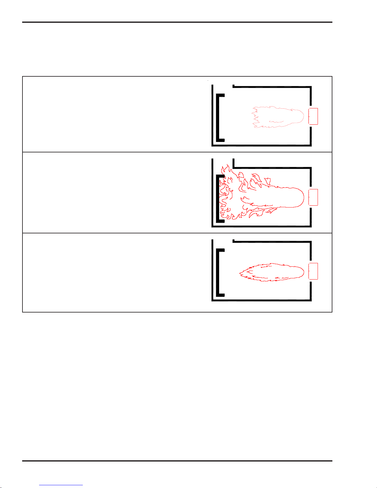
Coil Tube Boiler Operator's Manual: Models CB-200-CTB, CB-350-CTB and CB-500-CTB (230 V / 50 Hz)
Starting the Burner (continued)
Correct Maximum Flame Adjustment
(Proper Oil and Air Pressure)
• Flame goes half of the way down the
combustion chamber.
• Flame does not touch back of walls of
combustion chamber.
Incorrect Flame Adjustment
(Not Enough Combustion Air)
• Flame must not touch back or walls of
combustion chamber.
• Increase combustion air by opening the
air band on the side of the burner.
Incorrect Flame Adjustment
(Air Pressure too high)
• Ensure proper air pressure setting
Figure 6B - Flame Length Adjustment
4. Check the flame length after the burner has fired for 15 minutes.
5. Tighten the locking nuts on the air regulator.
I88372
6-4

Coil Tube Boiler Operator's Manual: Models CB-200-CTB, CB-350-CTB and CB-500-CTB (230 V / 50 Hz)
Starting the Burner (continued)
6. Checking for Proper CTB System Operation:
Observe the boiler temperature and water pressure.
7. After the burner stops running when the operating aquastat set temperature is reached, check the
following:
• air has been purged from water lines
• water pressure is satisfactory (i.e. not greater than 1.5 bar (22 psi); normal pressure is
0.8 bar (12 psi)
• all system controls functioning properly
8. Reset the operating aquastat to the normal operating range; 82 - 93
6 and 7, observing the CTB operation.
9. Reset the load temperature controller (i.e. thermostat or aquastat) to the normal operating
temperature.
10. As the CTB temperature drops, the burner will start running. Continue observing the CTB
operation through several burner ON/OFF cycles to ensure proper system performance.
11. Fine Tuning the Combustion Air Band:
NOTE: The initial setting of the combustion air band may require additional adjustment.
• Refer to Figure 6A to identify the combustion air band location on the burner.
• Observe the flame. The flame should be yellow-white with sharp tips and no "sparkles."
• If the flame is orange in color or the flame length is too long, the oil you are burning
requires MORE combustion air. OPEN the air band 3 mm (1/8") to 6 mm (1/4"), and re-check
the flame for the proper characteristics.
• Re-check the flame after five minutes. You should see a yellow-white flame with sharp
tips and no "sparkles", and the flame should extend half of the way down the combustion
chamber.
12. Checking for a Smokeless Burn:
Check for a smokeless burn by observing the stack while the burner is running. If you see any
smoke, repeat the previous steps for setting the combustion air band and adjusting the air
regulator. After adjusting the combustion air band, re-check the flame length.
NOTE: Check for a smokeless burn periodically (as you do the flame length). Immediately
readjust the burner if you ever see smoke coming from the stack. Smoke indicates improper air/
fuel adjustment.
NOTE: When using instruments to adjust the burner for a smokeless burn, the following
readings should be achieved:
• Draft over fire should be -0.02 to -0.04 inch w.c.
• Adjust for a smoke spot of a trace to 2
• For the CB-500-CTB adjust for a CO2 reading of 12.5 to 14% or an O2 reading of 2 to 4%
• For the CB-350-CTB adjust for a CO2 reading of 12 to 13.5% or an O2 reading of 4 to 7%
• For the CB-200-CTB adjust for a CO2 reading of 10.5 to 12.5% or an O2 reading of 3 to 5%
• Cad cell reading of 200 to 500 ohms
o
C (180 - 200 oF) and repeat steps
NOTE: On the CB-200-CTB the flame can not be observed through the inspection door. The
CB-200-CTB must be adjusted with instruments for proper combustion. Obtain the above settings
by adjusting the air band 10 mm (3/8") to 13 mm (1/2"). The metering pump will deliver a constant oil
flow and set the flame length.
6-5

Coil Tube Boiler Operator's Manual: Models CB-200-CTB, CB-350-CTB and CB-500-CTB (230 V / 50 Hz)
6-6

Coil Tube Boiler Operator's Manual: Models CB-200-CTB, CB-350-CTB and CB-500-CTB (230 V / 50 Hz)
SECTION 7: RESETTING THE OIL PRIMARY CONTROL
Understanding the Danfoss Oil Primary Control
The oil primary control will shut the oil pump and oil solenoid off when it detects flame-out during burner
operation. The oil primary control will then wait approximately 15 seconds (while the burner motor, air
solenoid, and transformer are energized) and attempt to re-ignite the burner (recycle mode). If the burner does
not re-ignite, the control will shut the burner off on safety lock-out. The following procedure explains what
should be done when this occurs. It is very important that you follow these instructions precisely when
resetting the safety on the primary control and restarting the burner.
Resetting the Danfoss Oil Primary Control
DANGER! DO NOT reset the oil primary control if oil mist is present in the combustion
chamber or when the combustion chamber is hot! DO NOT operate your CTB if excess oil,
oil vapor or fumes have accumulated in or near your boiler. As with any oil burning appliance, improper
operation may result in a fire or explosion hazard.
1. Refer to Figure 7A.
2. Allow 5 to 10 minutes for all fuel mist to exhaust from the combustion chamber.
3. If the combustion chamber is hot, allow the boiler to cool for at least 30 minutes. DO NOT
push the reset button.
4. When you are sure that all fuel mist has cleared and the boiler has cooled, push in and hold the
reset button for three seconds, then release. This will reset the control at any time during its operation.
5. If the burner will not restart, call your Clean Burn dealer immediately.
I88853A
Figure 7A - Danfoss Oil Primary Control
7-1

Coil Tube Boiler Operator's Manual: Models CB-200-CTB, CB-350-CTB and CB-500-CTB (230 V / 50 Hz)
7-2
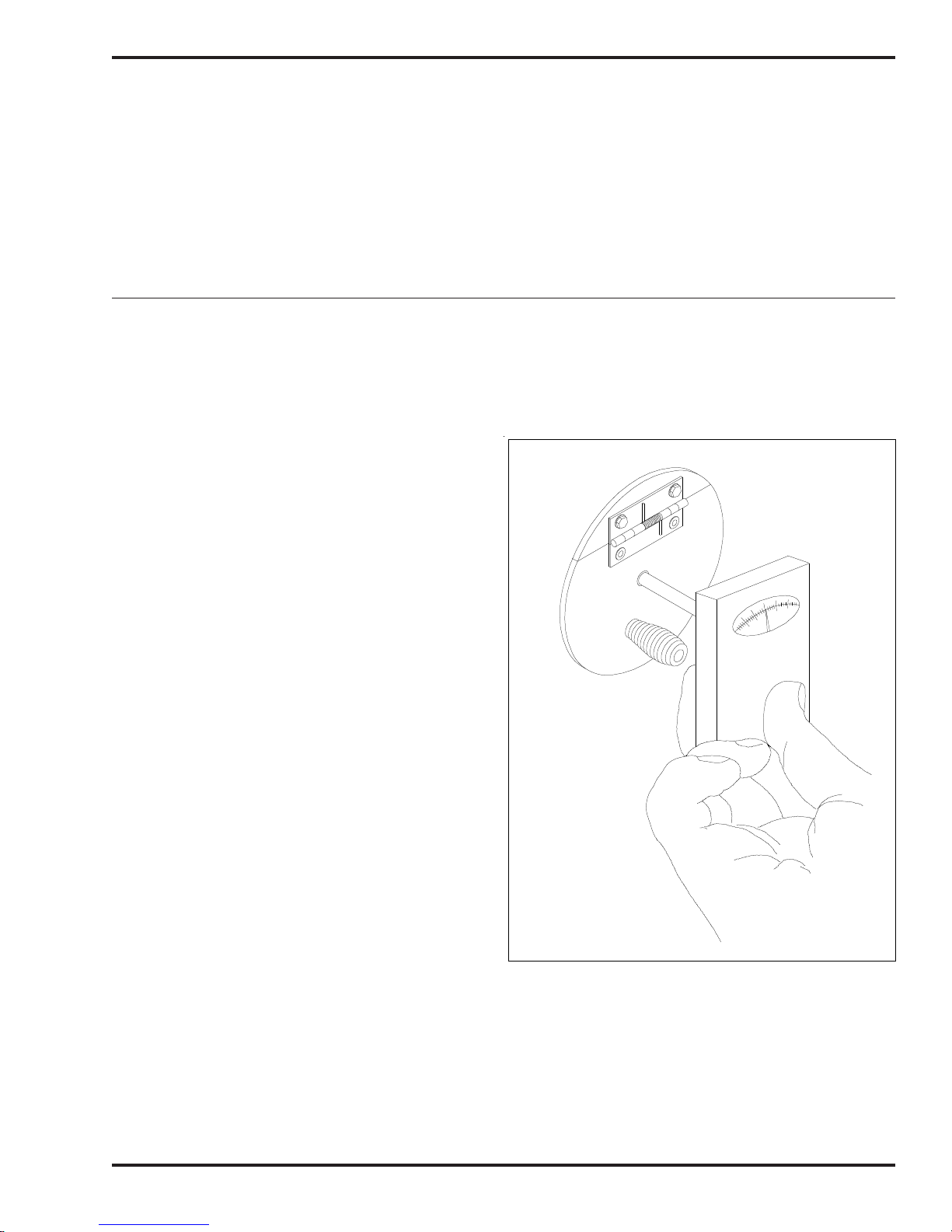
Coil Tube Boiler Operator's Manual: Models CB-200-CTB, CB-350-CTB and CB-500-CTB (230 V / 50 Hz)
SECTION 8: ADJUSTING THE DRAFT OVER FIRE
Understanding the Importance of Draft
Draft in the Coil Tube Boiler is created as the hot combustion gases rise up the stack, creating a negative
pressure inside the stack and the boiler. This negative pressure is measured as inches of water column
(W.C.) of draft. A proper draft overfire of -.02 w.c. is essential so that all combustion products travel
away from the burner, down the combustion chamber, through the boiler flues and up the stack.
Checking for Correct Draft Over Fire
NOTE: The CTB is equipped with an observation/draft reading port to check draft over fire. A qualified
serviceman with proper equipment must adjust your CTB for proper draft. Contact your Clean Burn
dealer for this service.
1. Insert the probe of the draft gauge
instrument into the draft reading port in the
observation port as shown in Figure 8A.
2. Adjust the barometric damper to achieve
the required draft over fire of -0.02 w.c.
(water column).
3. Record the reading in the Maintenance
Record located in the Appendixes.
4. If correct draft over fire cannot be achieved,
contact your Clean Burn dealer
immediately.
ATTENTION: Only operate your CTB
with a draft over fire of -0.02 w.c. Poor
draft results in back pressure and poor
burner performance. DO NOT operate your
CTB with a draft over fire greater than
-0.04 w.c.; an abnormally high stack
temperature may result from a draft over fire
that is too high.
ATTENTION: Backdraft must be resolved or
your boiler will not operate correctly!
Under backdraft conditions, draft overfire readings
will show positive pressure in the combustion
chamber. Backdraft means that oil spray,
combustion products, and heat are blown back against the burner. Backdraft results in oil-fouled
retention heads and electrodes. Severe backdraft will force heat back against the burner and result in
heat damage to the cad cell and transformer.
I88257
Figure 8A - Checking for Proper
Draft Over Fire
8-1

Coil Tube Boiler Operator's Manual: Models CB-200-CTB, CB-350-CTB and CB-500-CTB (230 V / 50 Hz)
Checking for Correct Draft Over Fire (continued)
Backdraft is caused by the following conditions:
• Poor draft caused by improper stack design. (See Section 4.)
• Poor draft caused by improper adjustment of the barometric damper.
• Incorrect combustion air band setting on the burner. (See Section 6.)
• Boiler flues are plugged with ash. (See Section 9.)
• Improper seal on clean-out door on back panel. (See Section 9.)
• Exhaust fans in your building are sucking gases down the stack.
Understanding the Effect of Exhaust Fans on Draft
Any type of exhaust fan, paint booth, or exhaust system in a building will create negative pressure in the
building unless there is a source of make-up air (i.e. fresh air which enters the building and replaces the
air removed by the exhaust fans.)
If there is insufficient make-up air, the exhaust fan will suck air and combustion gases down the coil
tube boiler stack and create backdraft in the boiler. After the burner is shut down, the backdraft may
suck the residual heat out of the combustion chamber and into the burner causing damage to the burner.
Even if the exhaust fan is on another level of the building or in another room away from the boiler, the
exhaust fan will still create backdraft at the boiler.
Checking Draft Overfire to Determine Severity of Backdraft
The following procedure is an accurate method of determining how much backdraft is created by the
exhaust fans. Once this is determined, you can select the correct method for resolving the backdraft.
1. Turn off ALL exhaust fans and close ALL doors and windows in the building (any open door or
window will allow make-up air to enter the building and will negate the test).
2. Start the coil tube boiler and adjust the barometric damper so that the draft overfire is -.02 w.c.
3. Check the draft overfire again. Now have someone start the exhaust fans.
4. Note how much the draft overfire has changed.
ATTENTION: If the draft overfire changed towards positive, it is mandatory that make-up air
is provided to the building or severe damage to the boiler and burner will occur. If the draft overfire
remained constant at -.02 w.c., there is sufficient make-up air entering the building, and the exhaust fan
is not adversely affecting the draft.
CAUTION: Under no circumstances should the equipment room ever be under a negative
pressure. Look for exhaust fans, compressors, air handling units, or anything else that may take air
away from the boiler. Also look for chemical fumes, solvents, refrigerants, etc. that may be in use around the
boiler and cause damage to it.
8-2

Coil Tube Boiler Operator's Manual: Models CB-200-CTB, CB-350-CTB and CB-500-CTB (230 V / 50 Hz)
Adjusting Draft Over Fire with A Draft Inducer Installed
NOTE: The draft inducer is purposely sized to create a generous draft. When adjusting the barometric
damper, you will find that the flapper is open most of the time. This allows the draft inducer to suck cool air
through the damper to protect the inducer motor from heat damage.
1. Use a draft gauge to check draft over fire.
2. Adjust the barometric damper to obtain -0.02 w.c. draft over fire. If you still have too much draft,
adjust the draft plate on the draft inducer. Move the plate in 1/4" to reduce the draft. Recheck
the draft reading.
8-3

Coil Tube Boiler Operator's Manual: Models CB-200-CTB, CB-350-CTB and CB-500-CTB (230 V / 50 Hz)
8-4

Coil Tube Boiler Operator's Manual: Models CB-200-CTB, CB-350-CTB and CB-500-CTB (230 V / 50 Hz)
SECTION 9: MAINTENANCE
Understanding Maintenance
Maintaining your Clean Burn CTB is an important activity which includes several periodic maintenance
activities and an annual burner tune-up...all are necessary to keep your boiler running in peak condition.
WARNING: Failure to maintain and/or improper servicing by unqualified personnel may
adversely affect the proper, safe operation of your coil tube boiler, may reduce the service
life of your boiler, and may void your warranty.
The following chart summarizes all the maintenance activities which should be performed on the CTB at
the intervals indicated. Instructions/procedures for these activities are included in this chapter.
Maintenance Activity Interval
Cleaning the canister filter Before vacuum gauge reads 10" HG of vacuum
Servicing the metering pump At least once a year
Cleaning the check valve/screen At least once a year
Cleaning water/sludge out of oil tank At least once a year
Cleaning out ash (CB-200-CTB)* Approx. every 750 hrs. per burner hour meter
Cleaning out ash (CB-350-CTB)* Approx. every 1000 hrs. per burner hour meter
Cleaning out ash (CB-500-CTB)* Approx. every 1000 hrs. per burner hour meter
Checking boiler water condition Periodically by qualified water treatment company
Annual burner tune-up At least once a year
*It is very important to clean the ash from the CTB on schedule. Normal use of the boiler requires
clean-out at least twice during the heating season. Heavy, around-the-clock usage requires more
frequent clean-out (e.g. one month of continual running of the boiler is 720 hours).
NOTE: IMPORTANT! Record all maintenance activities in the Maintenance Record provided in the
Appendixes.
Annual Preventative Maintenance and Burner Tune-up
The Clean Burn CTB requires annual preventative maintenance. The burner also requires an annual
tune-up to keep it running in peak condition. The burner tune-up should be performed by a qualified
Clean Burn service technician who has the necessary parts and expertise.
Contact your local Clean Burn dealer to schedule the annual maintenance for your boiler. Various
levels of service are provided to fit your particular need. This work is usually performed during the
warm-weather months to prepare the boiler for the next heating season.
9-1

Coil Tube Boiler Operator's Manual: Models CB-200-CTB, CB-350-CTB and CB-500-CTB (230 V / 50 Hz)
Cleaning the Canister Filter
ATTENTION: Never operate the oil pump with more than 10" HG of vacuum on the vacuum gauge.
High vacuum on the suction side of the pump separates air from the oil (cavitation) and will cause the
burner to shut down.
The following protective gear should be worn when cleaning the filter:
• Rubber gloves • Safety goggles
1. Close the ball valve adjacent to the filter.
2. Position a container under the filter.
3. Unscrew the four bolts, remove the canister bowl, and filter element. Now pour the oil into the
container.
4. Clean the filter element and the bowl in a parts washer.
5. Referring to Figure 9A, check the condition of the O-rings. Replace any that are cracked or
worn.
6. Ensure that the canister filter is 100% airtight by firmly tightening the four bolts.
7. Open the ball valve. Refer to Sections 5 and 6 for instructions on priming the pump and starting
the burner.
USE A RATCHET WRENCH WITH A 6" EXTENSION
AND 3/16" "ALLEN" SOCKET TO REMOVE THE
FOUR "ALLEN" SCREWS
TO BURNER
RETURN BACK
TO TANK
I88716−C
Figure 9A - Canister Filter Component Detail
9-2

Coil Tube Boiler Operator's Manual: Models CB-200-CTB, CB-350-CTB and CB-500-CTB (230 V / 50 Hz)
Servicing the Metering Pump
1. Refer to Figure 9B.
2. Remove the pump head cover (part 1).
3. Remove the screen (part 2) and wash it.
4. Remove and discard the used gasket (part 3).
5. Install a new gasket (Clean Burn Part #32422).
6. Replace the screen and pump head cover.
3
2
1
A
P
4
2
3
3
N
2
o
P
R
T
A
Figure 9B - Servicing the Metering Pump
2
4
2
2
3
N
o
R
T
9-3
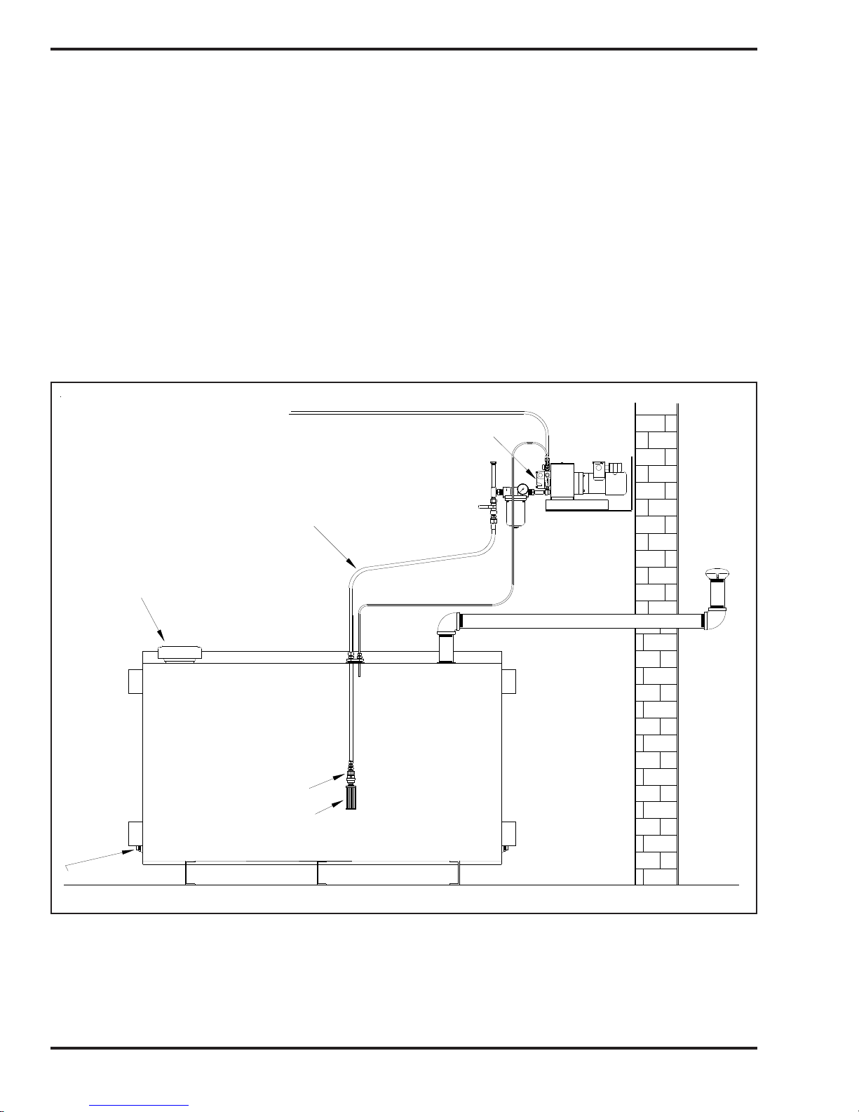
Coil Tube Boiler Operator's Manual: Models CB-200-CTB, CB-350-CTB and CB-500-CTB (230 V / 50 Hz)
Cleaning the Check Valve / Screen
This procedure applies to coil tube boiler installations with inside and outside tanks. The following
protective gear should be worn when cleaning the check valve/screen:
• Rubber gloves
• Safety goggles
1. Refer to Figure 9C. Remove the one-piece suction oil line from the tank.
2. Remove the check valve and screen. Clean these components in a parts washer.
3. Check the operation of the check valve. The valve must seat so it is airtight to hold pump prime.
4. Re-assemble and re-install the components. Apply Permatex #2 non-hardening gasket sealer or
equivalent to the threaded fittings. Firmly tighten all connections so the suction line is 100%
airtight.
5. Follow pump priming instructions in Section 5 to re-establish prime.
TO BURNER
METERING PUMP
EMERGENCY
VENT VALVE
CLEAN OUT
SUCTION
OIL LINE
VENT
CAP
945 LITER TANK
(250 GALLONS)
CHECK VALVE
CHECK VALVE SCREEN
I88717−C
Figure 9C - Check Valve Detail
9-4

Coil Tube Boiler Operator's Manual: Models CB-200-CTB, CB-350-CTB and CB-500-CTB (230 V / 50 Hz)
Cleaning the Ash from the Coil Tube Boiler
ATTENTION: Your CTB may require frequent clean out of the ash due to contaminants in the oil or
heavy use. As ash accumulates, CTB heat output declines, and the stack temperature rises. 3 mm (1/8") of ash
has the insulating capacity of 2.5 cm (1") of fiberglass insulation and reduces heat transfer significantly. Never
allow more than 6 mm (1/4") of ash to accumulate in the combustion chamber heat exchanger flues or stack.
The following protective gear should be worn when cleaning the ash:
• Respirator for fine particles • Rubber gloves
• Safety goggles • Protective clothing
1. Ensure that power has been turned OFF, and all "hot" components have been allowed to cool
sufficiently. Shop air should be turned OFF and disconnected. Allow at least one hour for the
ceramics to cool.
2. Clean the ash from the combustion chamber (see Figure 9D):
a. If the air and oil lines must be disconnected to open the clean out door:
1. Bleed-down pressure on the air and oil lines by slightly loosening the fittings at the bottom of
the connector block.
2. With air and oil pressure completely bled off, disconnect the air and oil pressure lines from
the bottom of the connector block.
NOTE: Cover these lines to keep dirt from entering the air/oil supply.
b. Remove the lock nuts on the clean-out door.
c. Carefully swing open the clean-out door to expose the coiled heat exchanger, flue passages,
and the combustion chamber.
d. Remove the two ceramic sleeve half-pieces from the combustion chamber, and remove the
supporting ceramic stand pieces.
e. Use a wire or bristle brush to thoroughly clean out the ash from the combustion chamber and
flue passages.
f. While cleaning out the combustion chamber, also check the burner retention head and throat.
Carefully clean these elements.
I88123-A
Figure 9D - Accessing the Combustion Chamber for Cleaning
ATTENTION: When cleaning the
combustion chamber, ensure that
you do not gouge or damage the
refractory material on the inside of
the clean-out door and target wall.
DO NOT bump or bend burner
components while cleaning the
combustion chamber.
9-5

Coil Tube Boiler Operator's Manual: Models CB-200-CTB, CB-350-CTB and CB-500-CTB (230 V / 50 Hz)
Cleaning the Ash (continued)
(2.) h. Thoroughly vacuum any remaining ash residue from the flue passages. A long wand on the
hose of your shop vac is helpful in reaching all the way back.
i. Inspect the combustion chamber and its components to ensure that it is in good condition.
Inspect the inside of the clean-out door and target wall. Make sure the refractory material on
the inside of the door is in good condition, and the door seals tightly when closed. If the
door does not seal tightly, replace any damaged components.
3. Clean the ash from the stack components:
a. Brush accumulated ash from the stack cap.
b. Lightly tap the stack components to loosen the ash.
c. Allow ash and dust to settle in the clean-out tee or elbow, then vacuum out.
d. Disconnect the stack from the CTB breach.
e. Thoroughly vacuum out the back of the boiler, including the boiler breach (through the
breach). If desired, the back panel can be removed for cleaning.
ATTENTION: When handling the front door and rear panel, be careful that you do not damage
the insulation seal surfaces. Two technicians may be required to remove and install the rear
panel safely. The panel weighs approximately 39 Kg (85 lbs).
4. Reassemble the boiler components (ceramic stand, ceramic sleeve, back panel, etc.) If necessary, refer
to Section 3 for additional Assembly information.
5. Close the clean-out door, install and tighten the washer and nuts. Make sure that the clean-out
door and rear panel close and seal properly. Reconnect all disconnected lines (oil and air) on the
bottom of the connector block.
NOTE: You may need to bleed air from the oil line before starting the burner. See Section 5
for pertinent instructions.
Cleaning the Oil Tank
DO NOT allow water, sludge, or other debris to accumulate in your oil supply tank to the point that
non-combustible or harmful materials are drawn into the pump or burner.
Drain water and sludge from the bottom of your tank at least once a year, and more frequently with
water accumulation.
End of Season Maintenance
Turn main power to your coil tube boiler OFF at the end of the heating season. Environmental regulations allow
your used oil to be burned only for "heat recovery." DO NOT operate your boiler during warm weather just to
burn oil. Contact your local Clean Burn dealer to schedule your annual burner tune-up. Allow only
trained, authorized service personnel to service your burner.
In the "off" season after the boiler has been cleaned, spray the combustion chamber with a light coat of
oil to reduce corrosion caused by moisture in the air.
NOTE: If the CTB is not used during the cold-weather months, it must be protected to prevent damage
from freezing temperatures.
9-6

Coil Tube Boiler Operator's Manual: Models CB-200-CTB, CB-350-CTB and CB-500-CTB (230 V / 50 Hz)
SECTION 10: THE CTB HYDRONIC SYSTEM
Understanding the CTB Hydronic System
The Clean Burn Coil Tube Boiler (CTB) is designed to function as a low-mass boiler (i.e. it will not
maintain boiler water temperature when there is no call for heat). Low-mass boilers require that a
sufficient, constant flow of water be maintained through the coil in order to: (a) remove the heat from
the boiler when the burner is firing AND (b) prevent the flow switch from shutting off the burner.
IMPORTANT NOTE: When designing the system layout and application for your CTB, keep in mind
that it is NOT suitable for open systems. The Clean Burn CTB has been designed to operate as a closed loop
boiler system. Potable water heating (i.e. for domestic or washing purposes) can be accomplished by incorporating a heat exchanger into the system.
Special Safety Guidelines for the Design and Installation of Hydronic Systems
Adhere to the following Safety Guidelines when designing and setting up the CTB hydronics system:
• The CTB must be installed on non-combustible flooring.
• The CTB must be installed in accordance with national, state, and local plumbing, heating,
and electrical codes and the regulations of the serving utilities which may differ from this
manual. Authorities having jurisdiction should be consulted before installations are made.
In all cases, reference should be made to all aplicable standards.
• The heating system must be designed by a competent hydronics contractor, and only persons
knowledgeable in the layout and installation of hydronic heating systems should install this
boiler.
• The boiler must be connected to an approved chimney in good condition. Serious property
damage could result if the boiler is connected to a dirty or inadequate chimney. The interior
of the chimney flue must be inspected periodically through the heating season for any
obstructions. A clean and unobstructed chimney flue is necessary to allow noxious fumes
that could cause serious injury to vent safely and will contribute toward maintaining
the boiler's efficiency.
• It is the responsibility of the installing contractor to see that all controls are correctly
installed and are operating properly when the installation is completed.
• To ensure optimum performance, qualified personnel must perform proper and timely
maintenance on the CTB according to the procedures provided in Section 9 of this manual.
10-1

Coil Tube Boiler Operator's Manual: Models CB-200-CTB, CB-350-CTB and CB-500-CTB (230 V / 50 Hz)
CTB System Function and Configuration
Water Flow and Temperature
The Clean Burn Coil Tube Boiler design requires continuous water flow through the boiler heat
exchanger to ensure proper system operation. The boiler circulator must be capable of developing
sufficient (head) pressure to overcome the resistance of the boiler plus the circulating system at the
required flow rate. If the water flow through the boiler is too low, the flow switch will not allow the
burner to operate. (Refer to Appendix A, as needed, for CTB system specifications.)
Heating systems using zone valves, zone pumps, or three-way valves may experience reduced water
flow through the boiler. This condition can cause excessive water temperature rise and unstable boiler
operation. The normal temperature rise across the boiler is 11 oC(20 oF). Minimum operating temperature
for the CTB is 71 oC (160 oF). To avoid condensation, the return water temperature should not fall below
60 oC (140 oF).
System Pressure
The Clean Burn CTB is designed to operate in closed, pressurized hydronic systems. Certain levels of pressure
are required for proper system operation--a minimum of 0.8 bar (12 PSI) should be maintained on the
system where the boiler supply water temperature is 93 oC (200 oF) or less. If a higher working pressure
is required, contact the Clean Burn Service Department for proper pressure requirements.
Sample System Configuration: Primary/Secondary Pumping System
A sample hydronic system setup using Clean Burn Coil Tube Boilers is shown in Figure 10A. This
system, a Primary/Secondary Pumping System, allows for many special hydronic requirements (e.g.
water return temperatures below the normal 60 oC (140 oF), variable flow zones, multiple zones, multi-temperature systems, and/or multiple boilers) and provides maximum flexibility while maintaining optimal system functioning. A critical advantage of this type of system is that it dramatically
reduces the danger of thermal shock to the boiler.
In a Primary/Secondary Pumping System (as shown in Figure 10A), the primary loop circulator runs
when any of the zones call for heat. In some system setups, the circulator may run continuously during
the heating season. The circulator pushes hot water past the zone tees; any of the secondary zone pumps
can draw hot water out of the first tee (as though the tee were a boiler). Each zone then returns cooler
water through the second tee where it mixes with the hot water being pushed through by the primary
loop circulator. The close positioning of the two zone tees is crucial to the operation of the system;
the tees must be at least 15 cm (6") but not more than 31 cm (12") apart. This allows for circulators of
different flow rates to be used in the same system while maintaining proper flow and functioning.
10-2

Coil Tube Boiler Operator's Manual: Models CB-200-CTB, CB-350-CTB and CB-500-CTB (230 V / 50 Hz)
WATER
COLD
CIRCULATOR
CONCEPTUAL SCHEMATIC:
THE DESIGNER MUST DETERMINE IF IT WILL WORK
WITHIN THE SYSTEM AND ENSURE COMPLIANCE
PRIMARY LOOP
WITH EXISTING CODES
AIR SEPARATOR
ENHANCED TYPE
WATER
HEATER
INDIRECT
ERGOMAX
DOMESTIC
HOT WATER
COLD
SUPPLY WATER
VALVEEXPANSION
FILL
WITH MULTIPLE OR SINGLE BOILERS
PRIMARY/SECONDARY SYSTEM
TANK
I88759−A
SECONDARY LOOPS
HYDRONIC
UNIT HEATER
CB 350 CTB
BASEBOARD ZONE
NO MORE THAN 30 cm (12") APART
TANK
EXPANSION
3−WAY MIXING
VALVE
OR TEMPERING
CB 350 CTB
CB 350 CTB
Figure 10A - Sample Primary/Secondary Hydronic System Diagram
PURGING VALVE
RADIANT FLOOR LOOP
LOOP
PRIMARY
OPTIONAL
FLOOR LOOP
IS USED IN THE RADIANT
REQUIRED IF ANTIFREEZE
CIRCULATOR MAY BE
HEAT EXCHANGER AND
10-3

Coil Tube Boiler Operator's Manual: Models CB-200-CTB, CB-350-CTB and CB-500-CTB (230 V / 50 Hz)
CTB Setup Options
When designing and setting up the CTB Hydronic System, please be aware of the following options and
special setup requirements:
(1) The boiler circulator (which you may have ordered from Clean Burn for your CTB system) is
sized to ensure a flow of water through the coil tube ONLY; it is NOT sized to be used as a system
circulator. An additional circulator must be installed to flow water through the system and to the boiler.
(2) In low load conditions, Clean Burn recommends the installation of a larger storage tank next to the
CTB to extend the run time and to reduce the occurrence of short cycling. Position the tank close to the
boiler to reduce the required connective piping as shown in sample configuration, Figure 10B.
(3) If hot water is required in the system installation for washing or other related activities, Clean
Burn offers Ergomax Heat Exchangers/Storage Tanks in 182, 273, and 450 liter sizes (48, 72, and 119
gallon sizes). Contact your local Clean Burn representative for additional details on these CTB system components. Refer to Figure 10C for a sample system configuration using an Ergomax Heat Exchanger. This
configuration is ideal for installations requiring pressure washing, car/truck washing, etc. The Ergomax unit
works well with a CTB because it stores boiler water in the tank and acts as a buffer (tempering) tank while
enabling reduction of short cycling.
10-4

Coil Tube Boiler Operator's Manual: Models CB-200-CTB, CB-350-CTB and CB-500-CTB (230 V / 50 Hz)
SYSTEM
SUPPLY
SYSTEM
RETURN
SYSTEM SUPPLY
CIRCULATOR
TANK
STORAGE
(BOILER WATER)
COLD
WATER
I88748−B
FILL VALVE
AIR ELIMINATOR
AIR SEPARATOR
ENHANCED TYPE
ISOLATION VALVE
USER SUPPLIED BOILER CIRCULATOR
PURGE VALVE
Figure 10B - Model CB-350-CTB with Additional Larger Storage Tank
CONCEPTUAL SCHEMATIC:
WILL WORK WITHIN THE SYSTEM AND
ENSURE COMPLIANCE WITH EXISTING CODES
THE DESIGNER MUST DETERMINE IF THIS SYSTEM
10-5

Coil Tube Boiler Operator's Manual: Models CB-200-CTB, CB-350-CTB and CB-500-CTB (230 V / 50 Hz)
WATER
INLET
I88749−B
HOT WATER
OUTLET
ERGOMAX
WATER HEATER
HEAT EXCHANGER
COLD
WATER
FILL VALVE
AIR ELIMINATOR
AIR SEPARATOR
ENHANCED TYPE
ISOLATION VALVE
USER SUPPLIED BOILER CIRCULATOR
PURGE VALVE
Figure 10C - CB-350-CTB with Ergomax Indirect Water Heater
CONCEPTUAL SCHEMATIC:
WILL WORK WITHIN THE SYSTEM AND
ENSURE COMPLIANCE WITH EXISTING CODES
THE DESIGNER MUST DETERMINE IF THIS SYSTEM
10-6

Coil Tube Boiler Operator's Manual: Models CB-200-CTB, CB-350-CTB and CB-500-CTB (230 V / 50 Hz)
Guidelines for CTB Setup and Operation
1. Refer to the appropriate illustration in this section for your CTB system configuration, as well as
Figures 4A/4B in the Installation chapter.
2. Connect the supply and return piping to the heating system. (Additional information in
Section 4).
CAUTION: Hot water pipes shall have clearances of at least 13 mm (1/2") from all combustible
surfaces. For additional technical reference material, see I=B=R Installation and Piping Guide
No. 200.
3. The relief valve must be installed with the spindle in the vertical position. The relief valve
discharge pipe must be extended to within four inches of the floor or to a drain.
4. To reduce the amount of cold water returned to the boiler (and to protect the boiler from thermal
shock), a return blend loop should be utilized.
5. Fill the entire heating system with water and vent air from the system according to the following
instructions:
(a) Close the isolation valve in the boiler supply piping.
(b) Isolate all circuits by closing the zone valves or balancing valves.
(c) Attach a hose to the purge valve located just below the isolation valve in the boiler supply
piping.
NOTE: Ensure that the end of the hose drains into a bucket located in a drain area or
outside.
(d) Starting with one circuit, open the first zone valve ONLY.
(e) Open the purge valve.
(f) Open the fill valve (the make-up water line should be located on the system side of the
isolation valve in the boiler supply piping.)
(g) Allow water to overflow from the bucket until discharge from the hose is bubble-free.
ATTENTION: Air in the hose may cause the hose to "jump" and water to spray out;
ensure that the area (and equipment nearby) is protected from any possible water damage.
(h) Open the zone valve to the second zone to be purged, then close the first. Repeat this step
until all zones have been purged, but always have one zone open. At completion, open all
zone valves.
(i) Close the purge valve, continue filling the system until the pressure gauge reads 0.8 bar (12 psi).
Close the fill valve.
NOTE: If the make-up water line is equipped with a pressure reducing valve, the system
will automatically fill to 0.8 bar (12 psi).
(j) Open the isolation valve in the boiler supply piping.
(k) Remove the hose from the purge valve.
( l) As soon as the boiler is filled, heat the water in the boiler to 82
water.
o
C (180 oF) to de-aerate the
10-7

Coil Tube Boiler Operator's Manual: Models CB-200-CTB, CB-350-CTB and CB-500-CTB (230 V / 50 Hz)
Guidelines for Preventing Oxygen Contamination
ATTENTION: Oxygen contamination of boiler water will cause corrosion of iron and steel boiler
components, and can lead to boiler failure (and void warranty). Causes of oxygen contamination
include:
• Addition of excessive make-up water as a result of system leaks
• Absorption through open tanks and fittings
• Oxygen permeable material in the distribution system
To ensure optimal CTB maintenance and operation, follow these recommendations to eliminate
damaging oxygen contamination:
• Repair system leaks to eliminate the need for the addition of make-up water
• Eliminate open tanks from the system
• Eliminate and/or repair leaky fittings
• Use non-permeable materials in the distribution system
• Isolate the boiler from the water heater system (i.e. wash and potable waters) by installing a
heat exchanger.
Guidelines for Initial Cleaning of the Hydronics System and Maintaining Water Quality
• Clean the boiler with an alkaline cleaner (e.g. soda ash or detergent) as recommended by a
qualified water treatment company.
NOTE: This is necessary to remove oil or other coatings from the tube surfaces. These
protective coatings are commonly applied to new tubes to prevent rusting during storage/
transit and will cause corrosion if left on the tubes during operation of the boiler.
• After cleaning the boiler, drain the system in a manner and to a location that hot water can be
discharged safely.
• Remove plugs from all available locations, and wash the water side of the boiler as
thoroughly as possible using a high-pressure water stream.
• Refill the system with fresh water.
• Test the pH of the water in the system. The pH should be higher than 8.5 but lower than 9.5.
Add appropriate boiler water treatment compounds as recommended by your qualified water
treatment company (if necessary) to bring the pH within the specified range.
• Heat the water in the boiler to 82 oC (180 oF) to de-aerate the water.
Guidelines for CTB Operation
After proper and safe CTB boiler setup and installation has been accomplished, CTB operation
proceeds as follows:
(a) Refer to Section 6 for instructions on starting the CTB.
(b) Following burner startup, set the operating control dial at 82 - 93 oC (180 - 200 oF).
ATTENTION: If, during normal operation, it is necessary to add water to your system more than
once a year, consult a qualified service technician to check your system for leaks. A leaky system will
increase the volume of make-up water supplied to the boiler which can significantly shorten the life of
the boiler and cause damage to the boiler.
10-8

Coil Tube Boiler Operator's Manual: Models CB-200-CTB, CB-350-CTB and CB-500-CTB (230 V / 50 Hz)
SECTION 1 1: TROUBLESHOOTING
The following charts and tables are provided for reference in troubleshooting any difficulties
encountered in boiler operation and adjustment.
• The Flow Chart outlines the proper sequence of events in boiler operation -- use this
chart to help diagnose where a problem may be occurring.
• More specific troubleshooting information is provided in the Troubleshooting Tables
following the flow chart. Each table lists a Problem, Possible Cause, and Possible
Action(s) to fix the problem.
The CTB sequence of operation is summarized as follows:
(1) A call for heat by the thermostat energizes the DPDT relay which in turn energizes the
circulator delay relay and the boiler loop circulator to establish a flow of water through the
coil.
(2) The flow switch closes. The power then continues from the flow switch through the high limit
aquastat, through the operating aquastat, and then to the burner.
(3) If the burner ignites within approximately 15 seconds and the photo unit sees a flame, the burner
will continue to operate until the call for heat is satisfied or the setting of the operating
aquastat is reached.
(4) If the thermostat is not satisfied, but the temperature setting of the operating aquastat is
reached, the burner will stop until the return water drops the water temperature in the boiler
(re-closing the operating aquastat and turning the burner back on).
(5) The boiler loop circulator will operate as long as the thermostat is calling for heat.
(6) The boiler loop circulator circuit includes a delay relay that keeps the circulator operating
approximately ten minutes after the call for heat is satisfied.
11-1

Coil Tube Boiler Operator's Manual: Models CB-200-CTB, CB-350-CTB and CB-500-CTB (230 V / 50 Hz)
Delay Relay
are energized
and the Boiler
Loop Circulator
closes
is energized
DPDT Relay
control is
energized
the oil primary
Wall thermostat or
aquastat calls for heat.
Flow Swith
Burner ignites.
and 210 µA indicating
Oil primary control receives
photo current between 50 µA
Oil primary control checks for
photo current less than 5 µA
chamber (NO FLAME)
indicating dark in the combustion
Oil primary control relay closes.
Burner ignition sequence begins.
proper ignition.
or aquastat is satisfied.
until the wall thermostat
Burner continues to run
opens and the burner
Primary control relay
shuts off.
FLOW CHART
230 V / 50 Hz
200 / 350 / 500 CTB
I88984A
INITIAL START-UP
BURNER PRE-IGNITION SEQUENCE
and DPDT relay circuit opens.
Wall thermostat or aquastat is satisfied
Yellow indicator
oil solenoid.
Pump circuit opens
When block temperature reaches 49 °C
and sends power to the oil primary control.
(120 °F) , the F120 proving switch closes
heater element and heats the block.
Preheater thermostat activates block
switch closes.
primary control receives power when the flow
F120 proving switch remains closed and oil
Air sensing switch closes
as it receives more than
NORMAL BURNER OPERATION
BURNER IGNITION SEQUENCE
heater element and maintains
60 °C (140 °F) block temperature.
Preheater thermostat cycles block
Air regulator adjusted to
INITIAL START-UP
0.7 bar (10 psi) of air
proper air pressure.
oil pump.
light ON.
Pump circ uit starts
pressure.
for proper combustion air.
Combustion air band adjusted
INITIAL START-UP
Hour meter starts.
Air sensing switch
centrifugal switch.
receives power from
BOILER HEATING SEQUENCE
sends power to air sensing
switch.
Centrifugal switch closes and
to heated area.
Hot water delivered
BOILER COOL DOWN SEQUENCE
stops running.
Boiler loop circulator
The Delay Relay keeps the boiler loop
circulator operating approximately ten
minutes after the call for heat is satisfied.
cut-off
and low water
Main power ON
sending power to
centrifugal switch
plugged in.
Green indicator
Burner cable
light ON.
Operating Aquastat senses water
temperature rise as the burner fires.
Air solenoid
electrode gap.
(15 sec.) spark at
providing interupted
14,000 volt igniter starts,
opens.
Burner motor starts and
reaches full rpm.
to drive latent heat from the CTB.
Boiler loop circulator continues to run
11-2
 Loading...