

CLEAN BURN CB-3500 series, CB-5000 series, CB-500 series Operator's Manual
OPERATOR'S MANUAL
CLEAN BURN MULTI-OIL FURNACE MODELS:
CB-3500 and CB-5000 with CB-500 Series BURNER
230 V / 50 Hz
W
3
s
z
0
1
H
0
s
t
6
-
0
5
0
4
2
0
2
2
s
s
o
f
n
4
a
6
D
O
6
H
3
B
0
7
e
p
H
7
y
5
T
0
.
r
N
FOR YOUR SAFETY −
DO NOT STORE GASOLINE
OR OTHER FLAMMABLE VAPORS AND LIQUIDS
I88911
IN THE VICINITY OF THIS OR ANY APPLIANCE!!
PUBLICATION DATE: 2/15/07, Rev. 10 CLEAN BURN PART #43143
WARNING: DO NOT assemble, install, operate, or maintain this equipment without first
reading and understanding the information provided in this manual. Installation and
service must be accomplished by qualified personnel. Failure to follow all safety precautions
and procedures as stated in this manual may result in property damage, serious personal injury
or death.
CLEAN BURN, INC. • 34 Zimmerman Road • Leola, PA 17540 • U.S.A.
The Clean Burn logo is a trademark of Clean Burn, Inc. All other brand or product names mentioned are the registered
trademarks or trademarks of their respective owners.
Copyright © 2007 Clean Burn, Inc. All rights reserved. No part of this publication may be reproduced, or distributed without
the prior written permission of Clean Burn, Inc. 34 Zimmerman Road, Leola, PA 17540. Subject to change without notice.


TABLE OF CONTENTS
SECTION 1: INTRODUCTION ................................................................................... 1-1
Guide to this Manual ..........................................................................................................1-1
For Your Safety... ..............................................................................................................1-2
Guidelines for Furnace Usage ......................................................................................1-4
Guidelines for Used Oil Tanks .....................................................................................1-5
Safety Labels ..............................................................................................................1-6
SECTION 2: UNPACKING ......................................................................................... 2-1
Removing the Shipping Crate ..........................................................................................2-1
Unpacking and Inspecting All Components..................................................................... 2-1
Furnace Component List ........................................................................................... 2-1
Unpacking Items Packed Inside the Furnace ................................................................2-2
SECTION 3: FURNACE ASSEMBLY......................................................................... 3-1
Understanding Assembly ................................................................................................. 3-1
Required Tools and Materials ................................................................................... 3-1
Installing the Blower Components .......................................................................................3-4
Installing the Blower (CB-5000 ONLY) ......................................................................3-4
Installing the Motor on the Blower ...............................................................................3-4
Wiring the Blower Motor.............................................................................................3-4
Installing the Motor Pulley, Blower Pulley, and V-Belt ..................................................3-6
Installing the Belt Guard and the Blower Guard ............................................................3-7
Installing the Hot Air Discharge Components ......................................................................3-8
Determining the Air Discharge Configuration ................................................................3-8
UNIT HEATERS: Installing the Air Discharge Louver Assembly .................................3-9
CENTRAL FURNACES: Installing Ductwork..........................................................3-10
Installing the Ceramic Target.............................................................................................3-10
Installing the Target on the Combustion Chamber .......................................................3-10
Closing the Furnace Door ..........................................................................................3-10
Installing the Burner ..........................................................................................................3-11
Checking the Burner Nozzle and Electrodes ...............................................................3-11
Mounting the Burner on the Hinge Bracket .................................................................3-12
Installing the Connector Block, Oil Line Tubing, and Air Line Tubing .................................3-13
Installing the Connector Block on the Furnace Door ...................................................3-13
Installing the Oil Line Tubing ......................................................................................3-13
Installing the Air Line Tubing ......................................................................................3-14
Locking the Burner into Firing Position .......................................................................3-15
Installing the Mounting and Stabilizer Brackets ..................................................................3-15
Installing the Brackets on the Furnace Cabinet............................................................3-15

TABLE OF CONTENTS
SECTION 4: FURNACE INSTALLATION .................................................................. 4-1
Understanding Installation ...................................................................................................4-1
Important Safety Guidelines for Safe Installation ...........................................................4-1
Important Notes to the Electrician ................................................................................4-2
Selecting a Location ...........................................................................................................4-4
Guidelines for Selecting a Location...............................................................................4-4
Mounting the Furnace.........................................................................................................4-5
Ceiling Mounting .........................................................................................................4-5
Raised Platform Mounting............................................................................................4-6
Floor Mounting ...........................................................................................................4-6
Oil Tank Installation Specifications......................................................................................4-8
Installing the Tank Vent and Emergency Vent ...............................................................4-9
Installing the Metering Pump .............................................................................................4-10
Preparing for Installation ............................................................................................4-10
Standard Mounting: Vertical Positioning .....................................................................4-10
Alternate Mounting: Horizontal Positioning .................................................................4-12
Wiring the Furnace and Pump...........................................................................................4-13
Wiring to the Furnace ................................................................................................4-13
Wiring to the Metering Pump .....................................................................................4-13
Installing the Suction Oil Line Components........................................................................4-14
Installing the Pressure Relief and Low-Flow Check Valve .................................................4-17
Installing the Pressure Oil Line Components ......................................................................4-18
Installing the Compressed Air Line....................................................................................4-18
Installing the Stack ...........................................................................................................4-19
Installing the Interior Stack.........................................................................................4-20
Installing the Barometric Damper ...............................................................................4-22
Installing the Stack Penetration...................................................................................4-23
Installing the Exterior Stack........................................................................................4-23
Installing the Stack Cap .............................................................................................4-23
Installing the Draft Inducer .........................................................................................4-23
Installing the Wall Thermostat ........................................................................................... 4-25
Inspecting the Furnace Installation.....................................................................................4-25
SECTION 5: METERING PUMP PRIMING ................................................................5-1
Understanding Metering Pump Priming ...............................................................................5-1
Required Tools and Materials ......................................................................................5-1
Preparing the Burner for Use with the Metering Pump .........................................................5-2
Priming the Metering Pump.................................................................................................5-4
Vacuum Testing the Oil Pump.............................................................................................5-6
SECTION 6: STARTING AND ADJUSTING THE BURNER ......................................6-1
Understanding Burner Startup and Adjustment ............................................................... 6-1
Preparing the Burner for Startup ......................................................................................6-1
Starting the Burner ...........................................................................................................6-3
Checking the Operation of the Blower Motor .....................................................................6-5

TABLE OF CONTENTS
SECTION 7: RESETTING THE FURNACE AND BURNER...................................... 7-1
Understanding Furnace/Burner Shutdowns..........................................................................7-1
The Oil Primary Control .....................................................................................................7-1
Resetting the Oil Primary Control .................................................................................7-1
Understanding the Fan Switches and Hi-Limits....................................................................7-2
The Blower/Fan Switch ......................................................................................................7-2
The Fan Limit Control ........................................................................................................7-3
The Auxiliary Hi-Temp Limit Switch ...................................................................................7-4
SECTION 8: ADJUSTING THE DRAFT OVER FIRE ................................................8-1
Checking for Correct Draft Over Fire .................................................................................8-1
Adjusting the Barometric Damper .......................................................................................8-2
Adjusting Draft Overfire on Furnaces with Draft Inducers....................................................8-2
Solving Draft Overfire Problems .........................................................................................8-3
Understanding the Effect of Exhaust Fans on Draft .......................................................8-3
Checking Draft Overfire to Determine Severity of Backdraft.........................................8-3
Installing a Make-up Air Louver ..................................................................................8-5
SECTION 9: MAINTENANCE ....................................................................................9-1
Understanding Maintenance................................................................................................9-1
Periodic Burner Inspection .................................................................................................9-2
Cleaning the Canister Filter .................................................................................................9-3
Servicing the Metering Pump ..............................................................................................9-4
Cleaning the Check Valve / Screen .....................................................................................9-5
Cleaning the Tank ..............................................................................................................9-6
Cleaning Ash from the Furnace ...........................................................................................9-7
Annual Burner Tune-up ......................................................................................................9-9
End of Season Maintenance ...............................................................................................9-9
SECTION 10: TROUBLESHOOTING ......................................................................10-1
Flow Chart ......................................................................................................................10-2
Troubleshooting Tables ....................................................................................................10-3
APPENDIX A
Detailed Furnace Specifications ......................................................................................... A-1
Furnace Technical Specifications................................................................................. A-1
Burner Technical Specifications................................................................................... A-2
Furnace Dimensions ................................................................................................... A-3
Burner Components ................................................................................................... A-6
Removing the Nozzle for Cleaning ....................................................................... A-11
Furnace components ................................................................................................. A12
Blower components................................................................................................... A16

APPENDIX B
Wiring Diagrams ............................................................................................................... B-1
Furnace Wiring Diagram ............................................................................................. B-1
Burner Wiring Diagram ............................................................................................... B-2
Ladder Schematic ...................................................................................................... B-3
Metering Pump Wiring Schematic ............................................................................... B-4
APPENDIX C
Additional Requirements for the United Kingdom ............................................................... C-1
APPENDIX D
Furnace Service Record .................................................................................................... D-1
TABLE OF CONTENTS
Operator's Manual: Models CB-3500 and CB-5000 (230 V / 50 Hz)
SECTION 1: INTRODUCTION
Guide to this Manual
This manual contains all the information necessary to safely install and operate the Clean Burn, CE-certified,
230 V / 50 Hz Furnace Models CB-3500 and CB-5000. Consult the Table of Contents for a detailed list of
topics covered. You'll find this manual's step-by-step procedures easy to follow and understand. Should
questions arise, please contact your Clean Burn dealer before starting any of the procedures in this manual.
As you follow the directions in this manual, you'll discover that assembling and operating your new furnace
involves six basic activities as outlined here:
• UNPACKING .................................................................................................... (Section 2)
• ASSEMBLY....................................................................................................... (Section 3)
• INSTALLATION ................................................................................................ (Section 4)
• OPERATION
• Metering Pump Priming...................................................................... (Section 5)
• Starting and Adjusting the Burner..................................................... (Section 6)
• Resetting the Oil Primary Control...................................................... (Section 7)
• Adjusting the Draft .............................................................................. (Section 8)
• MAINTENANCE................................................................................................ (Section 9)
The manual also contains important and detailed technical
reference materials which are located at the back of the
manual in the Appendixes.
Please read all sections carefully--including the following
safety information--before beginning any installation/
operation procedures; doing so ensures your safety and the
optimal performance of your Clean Burn Furnace.
WARNING!
STOP
YOUR SAFETY IS AT STAKE!
DO NOT INSTALL, OPERATE OR
MAINTAIN THIS EQUIPMENT
WITHOUT FIRST READING
AND UNDERSTANDING THE
OPERATOR'S MANUAL!
1-1
Operator's Manual: Models CB-3500 and CB-5000 (230 V / 50 Hz)
For Your Safety...
For your safety, Clean Burn documentation contains the following types of safety statements (listed here in order
of increasing intensity):
• NOTE: A clarification of previous information or additional pertinent information.
• ATTENTION: A safety statement indicating that potential equipment damage may occur if
instructions are not followed.
CAUTION: A safety statement that reminds of safety practices or directs attention to unsafe
practices which could result in personal injury if proper precautions are not taken.
WARNING: A strong safety statement indicating that a hazard exists which can result in
injury or death if proper precautions are not taken.
DANGER! The utmost levels of safety must be observed; an extreme hazard exists which
would result in high probability of death or irreparable serious personal injury if proper
precautions are not taken.
In addition to observing the specific precautions listed throughout the manual, the following general
precautions apply and must be heeded to ensure proper, safe furnace operation.
DANGER! DO NOT create a fire or explosion hazard by storing or using gasoline or other
flammable or explosive liquids or vapors near your furnace.
DANGER! DO NOT operate your furnace if excess oil, oil vapor or fumes have
accumulated in or near your furnace. As with any oil burning appliance, improper installation,
operation or maintenance may result in a fire or explosion hazard.
WARNING: Ensure that your furnace is properly installed, adjusted, operated and maintained.
Improper installation, adjustment, operation, or maintenance can adversely affect the proper, safe
operation of your furnace and may cause serious personal injury/death.
WARNING: DO NOT add inappropriate or hazardous materials to your used oil, such as:
• Anti-freeze
• Carburetor cleaner
• Paint thinner
• Parts washer solvents
• Gasoline
• Oil additives
• Any other inappropriate/hazardous
material
WARNING: Burning chlorinated materials (chlorinated solvents and oils) is illegal, will
severely damage your heat exchanger, and adversely affect the proper, safe operation of your
furnace. Instruct your personnel to never add hazardous materials to your used oil.
1-2
Operator's Manual: Models CB-3500 and CB-5000 (230 V / 50 Hz)
For Your Safety... (continued)
WARNING: Never alter or modify your furnace without prior written consent of
Clean Burn, Inc. Unauthorized modifications or alteration can adversely affect the proper,
safe operation of your furnace.
WARNING: The burner which is shipped with your Clean Burn furnace is to be used only
with your furnace according to the instructions provided in this manual. DO NOT use the
burner for any other purpose!
WARNING: Electrical installation of the furnace is to be performed only by qualified
personnel (i.e. licensed electrician/engineer). Improper electrical installation can adversely
affect the proper, safe operation of the furnace and may cause serious personal injury/death.
WARNING: Install the furnace in an area away from the main shop traffic. It is essential for
personal safety that only manufacturer-trained, qualified personnel have access to operate
and maintain the furnace. Only OFTEC or Manufacturer-trained and registered
technicians should install, commission, and service the equipment.
WARNING: To prevent damage to the furnace and to ensure personal safety, lifting, mounting,
and hanging of the furnace must be performed in accordance with safe handling procedures.
WARNING: DO NOT operate your furnace when the ambient temperature is above
35o C (95o F).
WARNING: The Best Operator is a Careful Operator! By using common sense,
observing general safety rules, and adhering to the precautions specific to the equipment, you,
the operator, can promote safe equipment operation. Failure to use common sense, observe
general safety rules, and adhere to the precautions specific to the equipment may result in
equipment damage, fire, explosion, personal injury and/or death.
WARNING: The installation, operation, and maintenance of this equipment must be
accomplished by qualified personnel and in compliance with the specifications in the
Clean Burn Operator's Manual and with all national, state, and local codes or authorities
having jurisdiction over environmental control, building inspection and fuel, fire and
electrical safety.
WARNING: This equipment is for commercial and/or industrial use only; it is NOT for
residential use.
WARNING: Call your Clean Burn dealer for service. DO NOT allow untrained, unauthorized
personnel to service your furnace. Make sure that your furnace receives periodic maintenance to
ensure optimal performance.
Failure to comply with these standards and requirements may result in equipment
damage, fire, explosion, personal injury and/or death.
1-3

Operator's Manual: Models CB-3500 and CB-5000 (230 V / 50 Hz)
For Your Safety... (continued)
Guidelines for Furnace Usage
• This furnace is designed to burn the following fuels:
• Used crankcase oil up to 50 SAE
• Used transmission fluid
• Used hydraulic oils
• #2, #4, and #5 fuel oils
NOTE: Used oils may contain other substances, including gasoline, that may hinder
performance.
• Make sure you comply with all environmental regulations concerning the use of your furnace.
These regulations require that:
• Your used oil is generated on-site. You may also accept used oil from
"do-it-yourself" oil changers.
• Hazardous wastes, such as chlorinated solvents, are NOT to be mixed with your
used oil.
• The flue gases are vented to the outdoors with an appropriate stack.
• Your used oil is recycled as fuel for "heat recovery". DO NOT operate your boiler
in warm weather just to burn oil.
Contact your Clean Burn dealer for current environmental regulations.
• If your furnace ever requires service, call your Clean Burn dealer. DO NOT allow untrained,
unauthorized personnel to service your furnace. Make sure that your furnace receives annual
preventative maintenance to ensure optimal performance.
1-4
Operator's Manual: Models CB-3500 and CB-5000 (230 V / 50 Hz)
For Your Safety... (continued)
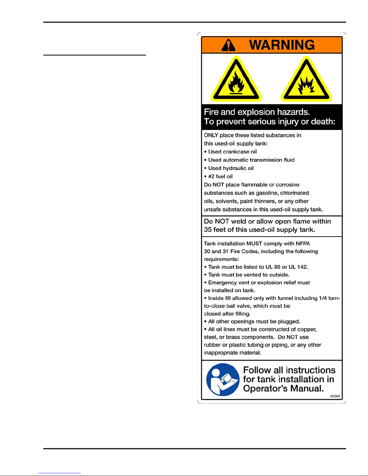
Guidelines for Used Oil Tanks
For the safe storage of used oil and the safety of
persons in the vicinity of the used oil supply tank,
ensure that your tank installation adheres to the
following safety guidelines:
• The tank installation must meet all
national and local codes. Consult your
local municipal authorities for more
information as necessary.
• Review and adhere to the safety
guidelines for used oil supply tanks
as stated in the WARNING shown.
• Ensure that the tank for your furnace
installation complies with all code and
safety requirements as stated here. If the
tank does not comply, DO NOT use it.
• If you do not have a copy of the tank
safety label pictured at right, please
contact your Clean Burn dealer for the
label, which is to be affixed directly on
your used oil supply tank.
1-5
Operator's Manual: Models CB-3500 and CB-5000 (230 V / 50 Hz)
For Your Safety... (continued)
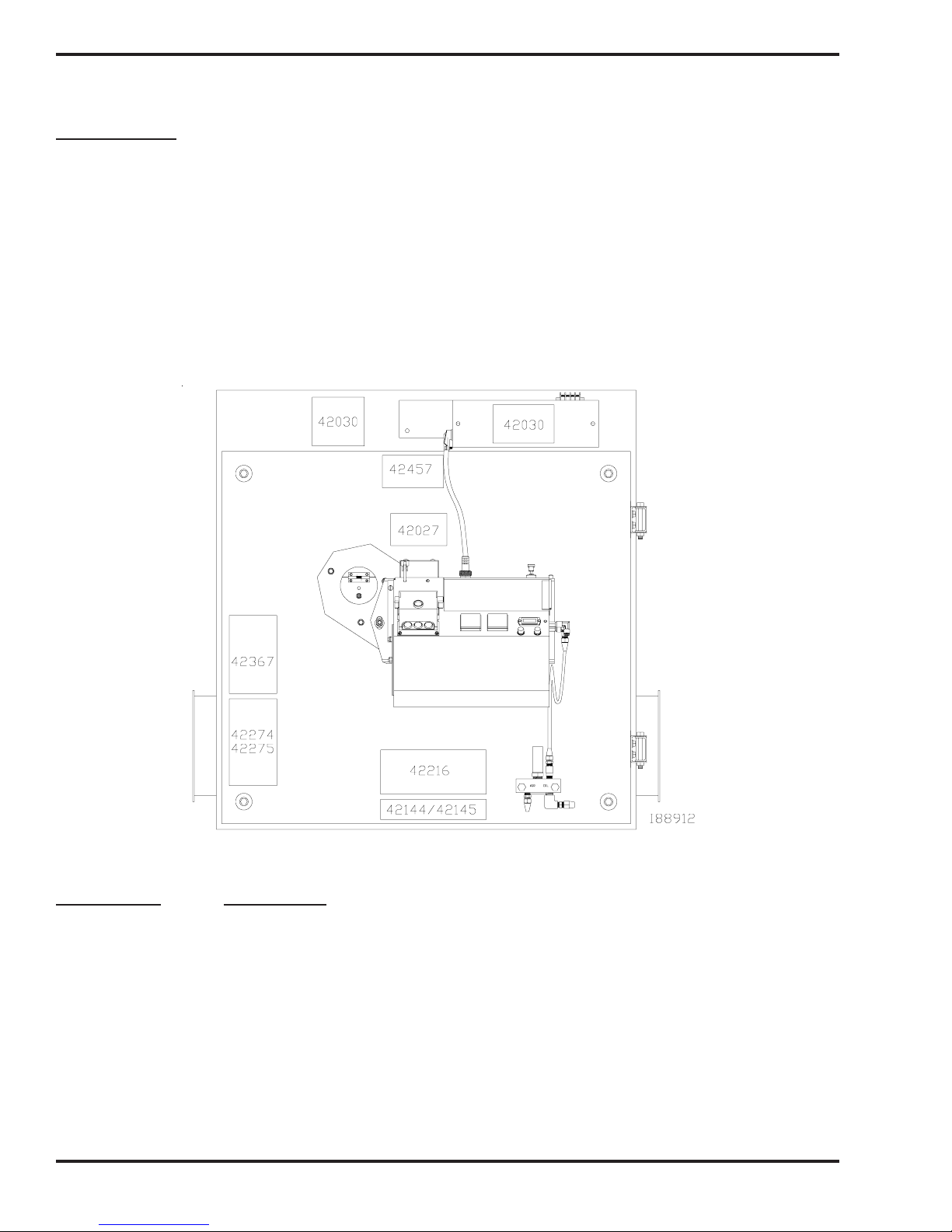
Safety Labels
Following are the locations and descriptions of all labels on your CB-3500 or CB-5000 furnace. The following
illustrations show the location of ALL labels on your furnace. Please note that some labels denote model
number, model description, etc. while others contain important safety messages.
Each Safety Label contains an important safety message starting with a key word as discussed earlier in this
section (e.g. ATTENTION, CAUTION, WARNING, DANGER). For your safety and the safe operation of
your furnace, review all labels and heed all safety messages as printed on the labels.
If any labels on your Clean Burn furnace ever become worn, lost or painted over, please call your Clean Burn
dealer for free replacements.
Danfoss 220− 240V 50− 60Hz 3W
ts 1 0s
Type BHO 64
Nr. 057H703 6
CB-3500/CB-5000 Furnace Cabinet Labels
Label Part # Description
42030 Furnace Electrical Shock Hazard Warning Label (several locations)
42457 Made in USA Label
42027 Furnace Burn Hazard/Hazardous Voltage Warning Label
42367 Furnace Safety Warning Label (Multiple Messages - Fire/Shock/Burn Hazards)
42274 Data Label - CB-3500 CE
42275 Data Label - CB-5000 CE
42216 Clean Burn Logo Label
42144 Model CB-3500 Label
42145 Model CB-5000 Label
42068 Furnace Blower/Fan Entanglement Hazard Warning Label (not shown - positioned
near blower)
1-6
Operator's Manual: Models CB-3500 and CB-5000 (230 V / 50 Hz)
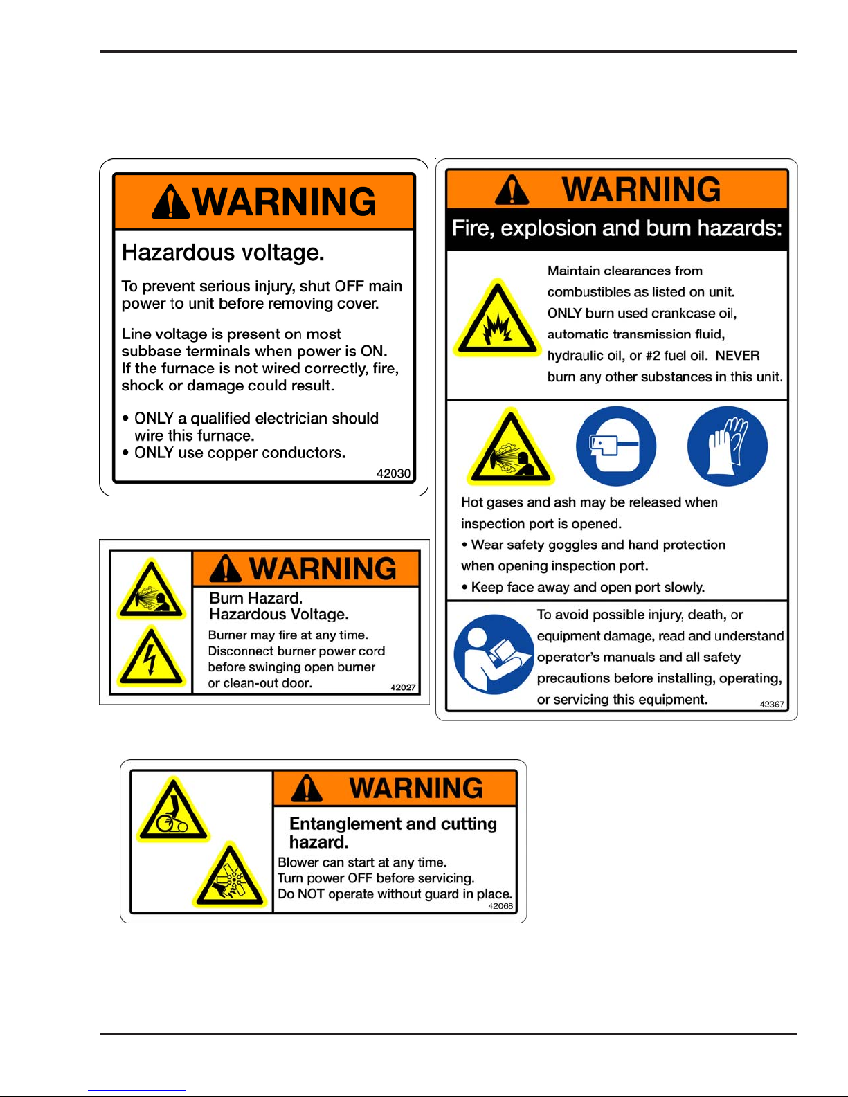
For Your Safety... (continued)
CB-3500/CB-5000 Furnace Cabinet Safety Labels
1-7

Operator's Manual: Models CB-3500 and CB-5000 (230 V / 50 Hz)
For Your Safety... (continued)
CB-3500 / CB-5000 Furnace Cabinet Safety Labels (continued)
LEOLA, PENNSYLVANIA (USA)
LABEL SERI AL NO.
MULT−OIL BURNING UNIT HEATER
WHEN USED WITH THE FOLLOWING
LISTED FUELS
CB 3500
INPUT RATING W/NO. 2 FUEL OIL
9.5
2.5
9.5
2.5
2.5
9.5
2.5
9.5
2 (5)
60 (152)
POWER
2
1/6
1/10
450
1/50
1/3
BTU/HR
350,000
16.0
16.0
16.0
16.0 1.1
230 8.5
230
230
230
230
230
1.1
1.1
1.1
18 (46)
18 (46)
89/392/EEC 72/23/EEC 89/336/EEC
(KW)
103
6.0
6.5
6.0
6.0
1.3
0.45
1.7
0.5
1.8
12
20
0.41
0.45
0.41
0.41
−0.06 (−1.5 mm)
24 (61)
24 (61)
HZ
50
50
50
50
50
50
LEOLA, PENNSYLVANIA (USA)
LABEL SERIAL NO.
MULT−OIL BURNING UNIT HEATER
WHEN USED WITH THE FOLLOWING
LISTED FUELS
CB 5000
INPUT RATING W/NO. 2 FUEL OIL
13.5
3.6
13.53.6
3.6
13.5
3.6
13.5
2 (5)
60 (152)
POWER
2
1/6
1/10
450
1/4
18.0
16.0
16.0
18.0
230
230
230
230
230
BTU/HR
500,000
18 (46)
18 (46)
1.2
1.1
1.2
9.0
1.3
0.45
1.7
1.3
15
20
89/392/EEC 72/23/EEC 89/336/EEC
(KW)
147
2.5
3.01.1
3.0
3.0
−0.06 (−1.5 mm)
24 (61)
24 (61)
HZ
50
50
50
50
50
0.17
0.21
0.21
0.21
THE MAINTENANCE INTERVAL FOR CLEANING ASH FROM THE FURNACE IS
APPROXIMATELY 700 HOURS. THE ASH LEFT FROM THE BURNING OF USED OIL
MAY CONTAIN METALLIC COMPOUNDS OR FOREIGN MATERIALS. THE ASH MUST BE
THIS APPLIAN CE IS NOT TO BE USED WITH AIR FILTERS AND
SHALL INCORPORATE NO PROVISIONS FOR MOUNTING AIR FILTERS.
INSTALL AND USE ONLY IN ACCORDANCE WITH THE
MANUFACTURER’S INSTALLATION AND OPERATING INSTRUCTIONS.
DISPOSED OF PROPERLY.
BURNER REQUIRES A MINIMUM AIR SOURCE OF:
2 S.C.F.M. (57 L /MIN.) AT 25 P. S.I. (1.72 BAR).
FOR COMMERCIAL OR INDUSTRIAL USE ONLY.
AUTHORITIES HAVING JURISDICTION SHOULD
BE CONSULTED PRIOR TO INSTALLATION.
42274
THE MAINTENANCE INTERVAL FOR CLEANING ASH FROM THE FURNACE IS
APPROXIMATELY 700 HOURS. THE ASH LEFT FROM THE BURNING OF USED OIL
MAY CONTAIN METALLIC COMPOUNDS OR FOREIGN MATERIALS. THE ASH MUS T BE
BURNER REQUIRES A MINIMUM AIR SOURCE OF:
THIS APPLIANCE IS NOT TO BE USED WITH AIR FILTERS AND
SHALL INCORPORATE NO PROVISIONS FOR MOUNTING AIR FILTERS.
INSTALL AND USE ONLY IN ACCORDANCE WITH THE
MANUFACTURER’S INSTALLATION AND OPERATING INSTRUCTIONS.
DISPOSED OF PROPERLY.
2 S.C.F.M. (57 L/MIN.) AT 25 P .S.I. (1.72 BA R).
FOR COMMERCIAL OR INDUSTRIAL USE ONLY.
AUTHORITIES HAVING JURISDICTION SHOULD
BE CONSULTED PRIOR TO INSTALLATION.
1-8
42275
Operator's Manual: Models CB-3500 and CB-5000 (230 V / 50 Hz)
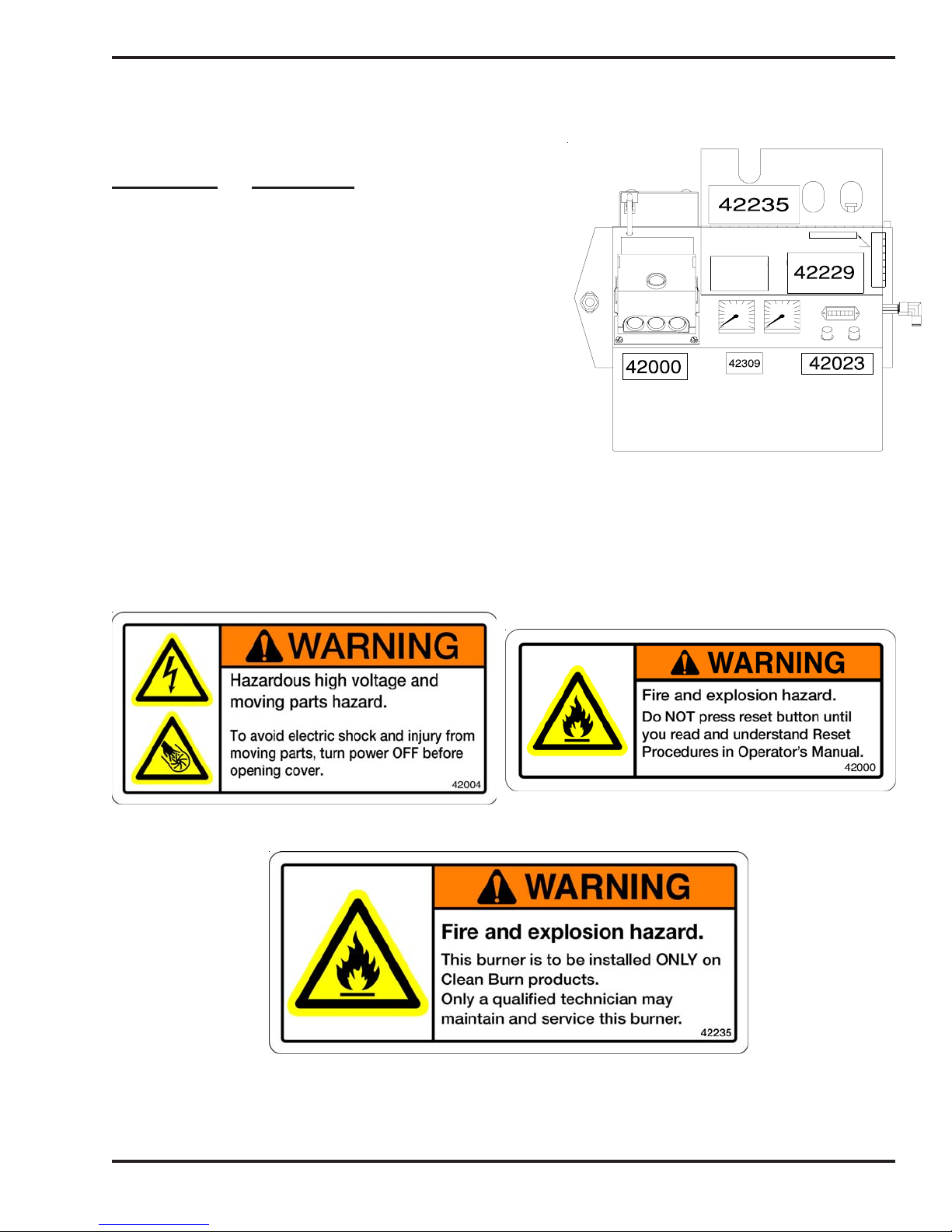
For Your Safety... (continued)
CB-3500 / CB-5000 Burner Labels
Label Part # Description
42005 Sold and Serviced By Label
42004 Burner Safety Warning Label
(High Voltage/Moving Parts Hazards)
42000 Burner Safety Warning Label
(Fire/Explosion Hazard - Reset Button)
42235 Burner Safety Warning Label
(Fire/Explosion Hazard - Burner Installation
and Service)
42339 CB-500-CE Burner Model/Serial Number Label
42340 CB-551-CE Burner Model/Serial Number Label
42197 Patent Pending Label
42229 Logo/Burner Description Label
42023 Burner Power Label
42004
Danfoss 220−240V 50−6 0Hz 3W
ts 10s
Type BHO 64
Nr. 057H7036
42197
42339/
42340
I88889
CB-3500/CB-5000 BurnerSafety Labels
1-9

Operator's Manual: Models CB-3500 and CB-5000 (230 V / 50 Hz)
1-10

Operator's Manual: Models CB-3500 and CB-5000 (230 V / 50 Hz)
SECTION 2: UNPACKING
Before assembling your furnace, you must accomplish the following activities described in this section:
• Removing the Shipping Crate
• Unpacking and Inspecting All Components
Removing the Shipping Crate
1. Carefully remove the top boards of the shipping crate. Then remove the front, back, and side
panels.
2. Carefully lift the furnace off the shipping pallet with a fork lift.
ATTENTION: DO NOT attempt to slide the furnace cabinet out of the shipping crate--you may
damage the furnace cabinet.
NOTE: DO NOT remove the squirrel cage blower from the furnace cabinet. (The blower is installed in final
position for Model CB-3500; it will require additional installation for Model CB-5000.)
Unpacking and Inspecting All Components
Following is an itemized list of all components you should have received in your Clean Burn furnace
shipment. Open all shipping containers and inspect all components according to the list. Immediately
notify the freight company and your Clean Burn dealer in case of shipping damage or shortage(s). Keep
all components together so you will have them as needed for furnace assembly and installation.
Furnace Component List
ONE SKID containing:
• Furnace cabinet
Components packed on top of furnace cabinet:
• Burner
• 2 HP Blower motor
• Blower
• Air discharge
Components packed inside furnace cabinet:
• Ceramic target
• Blower assembly components
• Oil pump
• Canister filter
• Vacuum gauge
• Check valve / check valve screen
• Wall thermostat
• Barometric damper
• Draft inducer (CB-5000 only)
• Connector block
• Assorted bolts/fittings, Assembly parts, Mounting components
NOTE: You may have received additional boxes or skids if you ordered optional accessories.
2-1
Operator's Manual: Models CB-3500 and CB-5000 (230 V / 50 Hz)
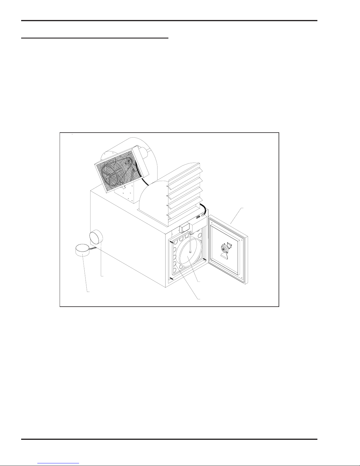
Unpacking Items Packed Inside the Furnace
To unpack the items packed inside the furnace cabinet (in the combustion chamber), you will need to
open the combustion chamber door.
1. Remove the four nuts and washers which hold the combustion chamber door closed. Set the nuts
and washers aside in a safe place for later re-installation after the target has been installed
(Section 3).
2. Carefully swing the clean out door open. Remove and inspect the components packed inside.
3. Leave the door unfastened (open) for assembly/installation procedures to be accomplished in the
next section.
CLEAN−OUT
BREACH
CLEAN−OUT
CAP
COMBUSTION
CHAMBER
FURNACE FLUE
Figure 2A - Accessing the Combustion Chamber
CLEAN−OUT
DOOR
I88913
2-2

Operator's Manual: Models CB-3500 and CB-5000 (230 V / 50 Hz)
SECTION 3: FURNACE ASSEMBLY
Understanding Assembly
Assembling your Clean Burn Furnace is a six-step process which includes:
(1) Installing the Blower Components
(2) Installing the Hot Air Discharge Components
(3) Installing the Ceramic Target
(4) Installing the Burner
(5) Installing the Connector Block, Oil Line Tubing, and Air Line Tubing
(6) Installing the Mounting and Stabilizer Brackets
Clean Burn recommends that you review all assembly procedures before proceeding, paying careful attention to
safety information statements. Please note that some assembly procedures apply only to certain furnace models.
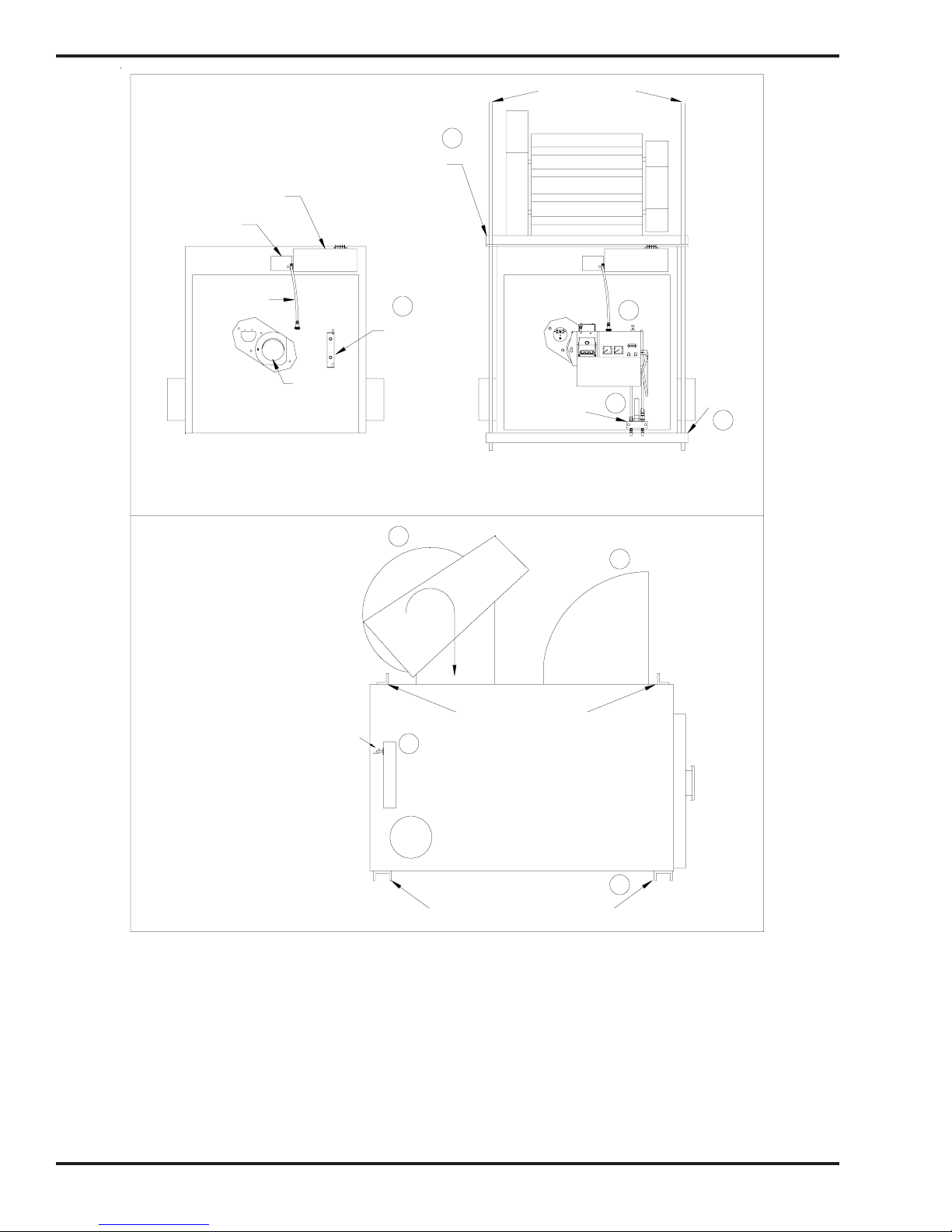
Figures 3A and 3B on the following pages provide a general overview of the furnace components and their
proper assembly and how the unit should look following proper assembly.
Required Tools and Materials
The following tools are required for furnace assembly and should be gathered before starting any procedures:
• Variable-speed electric drill
• 1/4" hex-nut driver attachment for electric drill
• Set of open-end wrenches (3/8" - 5/8")
• 6" adjustable wrench
• Medium straight-blade screwdriver
3-1
Operator's Manual: Models CB-3500 and CB-5000 (230 V / 50 Hz)
’ALL THREAD’ ROD
6
STABILIZER BRACKET
ON TOP OF FURNACE
JUNCTION BOX
FAN LIMIT
BURNER
CABLE
FURNACE DOOR
4
BURNER
MOUNT
THROAT
AIR DISCHARGE
CONNECTOR
BLOCK
4
220-240V 50-60Hz 3W
Danfoss
ts 10s
Type BHO 64
Nr. 057H7036
MOUNTING
BRACKET
BELOW
5
FURNACE
6
FRONT VIEW OF CABINET
PRIOR TO ASSEMBLY
NOTE: BLOWER MUST BE INSTALLED
WITH BULGE ON BLOWER FACING
BACK OF FURNACE. MAKE SURE
BLOWER WHEEL ROTATION IS
CLOCKWISE AS SHOWN
NOTE: LOOP ON TARGET HOOKS
OVER MOUNTING BRACKET ON
BACK WALL OF COMBUSTION
CHAMBER
SIDE VIEW OF CABINET
FRONT VIEW OF CABINET
AFTER ASSEMBLY
1
ROTATION
STABILIZER BRACKETS
3
TARGET INSTALLED
ON BACK WALL OF
COMBUSTION CHAMBER
FURNACE BREACH
MOUNTING BRACKETS INSTALLED
ON FURNACE CABINET BASE
2
AIR DISCHARGE
6
I88914
Figure 3A - Overview of Furnace Assembly
Complete assembly of the CB-3500/CB-5000 furnace according to the following list of activities as
illustrated above:
(1) Installing the Blower Assembly
(2) Installing the Hot Air Discharge Components
(3) Installing the Target
(4) Installing the Burner
(5) Installing the Connector Block, Oil Line Tubing, and Air Line Tubing
(6) Installing the Mounting and Stabilizer Brackets
NOTE: Corresponding procedures provided in order in this section.
3-2
Operator's Manual: Models CB-3500 and CB-5000 (230 V / 50 Hz)
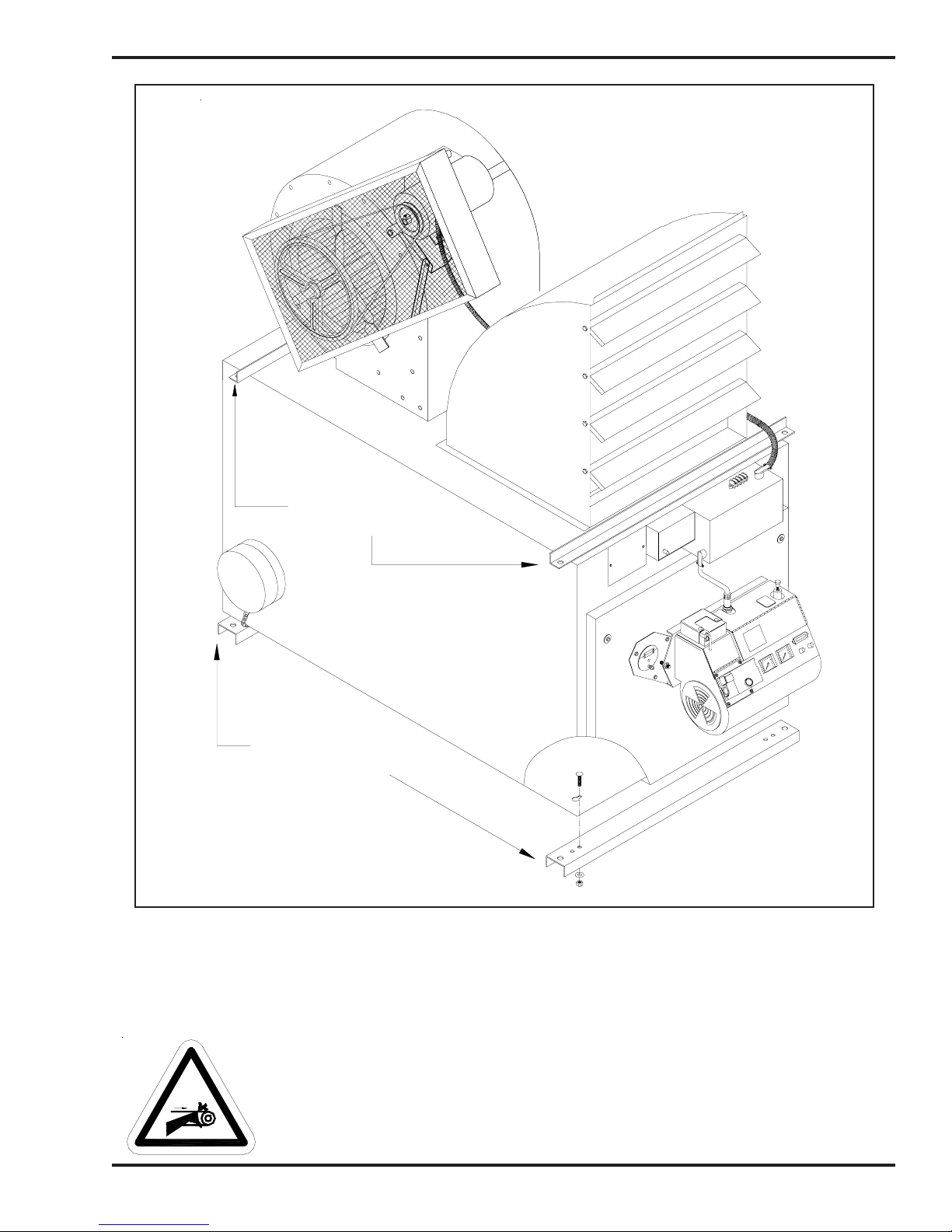
STABILIZER
BRACKETS
W
3
s
z
0
1
H
0
s
6
t
0
5
0
4
2
0
2
2
s
s
o
f
n
4
a
6
D
O
6
H
3
B
0
7
e
H
p
7
y
5
T
0
.
r
N
MOUNTING
BRACKETS
I88915
Figure 3B - Three-dimensional View - Furnace Completely Assembled
with Louver Assembled for Unit Heater Application
NOTE: This figure shows the mounting/stabilizer brackets in place for a ceiling mounted installation. If your
furnace will be floor or platform mounted, the brackets are not needed.
WARNING: Keep hands and fingers clear of the motor pulley or serious personal
injury may occur.
3-3

Operator's Manual: Models CB-3500 and CB-5000 (230 V / 50 Hz)
Installing the Blower Components
NOTE: The blower is installed in final position on the CB-3500 cabinet. The blower for the CB-5000
requires additional installation as described in the following procedure.
Installing the Blower (Model CB-5000 ONLY)
NOTE: For proper air flow through the furnace, the blower must be positioned so the bulge on the blower
faces toward the rear of the furnace as illustrated in Figures 3A, 3B, and 3D.
1. Remove the hex-head screws, which hold the blower in the shipping position.
2. Carefully slide the blower rearward on the cabinet into position against the blower inlet lip.
3. Use self-tapping screws to install the angle support at the back of the blower to complete the
blower inlet lip.
4. Install at least three (3) self-tapping screws to each side of the blower inlet to safely support the
blower.
Installing the Motor on the Blower
1. Refer to Figures 3C and 3D.
2. Use self-tapping bolts to install the motor mounting bracket on the blower according to the
dimensions provided in Figure 3C.
3. Slide the two (2) square-head bolts upside-down in the channel of the motor mounting bracket.
4. Install the motor mounting plate on the mounting bracket using the two bolts in the channel to
hold the plate in position. DO NOT install the nuts on the bolts yet. Make sure the plate is flush
with the side of the blower.
5. Use a self-tapping bolt to install the motor tensioning bracket on the blower according to the
dimensions provided in Figure 3C.
6. Lift up on the end of the motor mounting plate until the hole in the side of the plate is aligned
with the slot in the motor tensioning bracket. Push a bolt through the slot and install a nut
loosely just to hold the plate in position. DO NOT tighten the nut yet.
7. Lift the motor into position on the motor mounting plate using the two bolts in the channel to
hold the motor in place. Now loosely install the nuts on the two (2) bolts.
8. Slide the motor into position so the face of the motor is flush with the side of the blower. Now
tighten the nuts.
9. Install the additional two (2) bolts and nuts through the lower holes in the motor mounting plate
and motor. Tighten the nuts to hold the motor firmly in position.
Wiring the Blower Motor
WARNING: To avoid electrical shock, make sure the main power to the furnace is turned OFF
before wiring the blower motor.
1. Refer to the Furnace Wiring Diagram provided in Appendix B at the back of this manual.
2. Install the electrical cable between the electrical junction box on the front of the furnace and the
electrical access on the blower motor.
3. Connect the wires in the junction box according to the Furnace Wiring Diagram (Appendix B).
NOTE: The blower motor is rated for 220/240 volts, single phase. Make sure the proper electrical
circuit to the furnace has been provided by a qualified electrician as shown in the Furnace Wiring
Diagram.
3-4
Operator's Manual: Models CB-3500 and CB-5000 (230 V / 50 Hz)
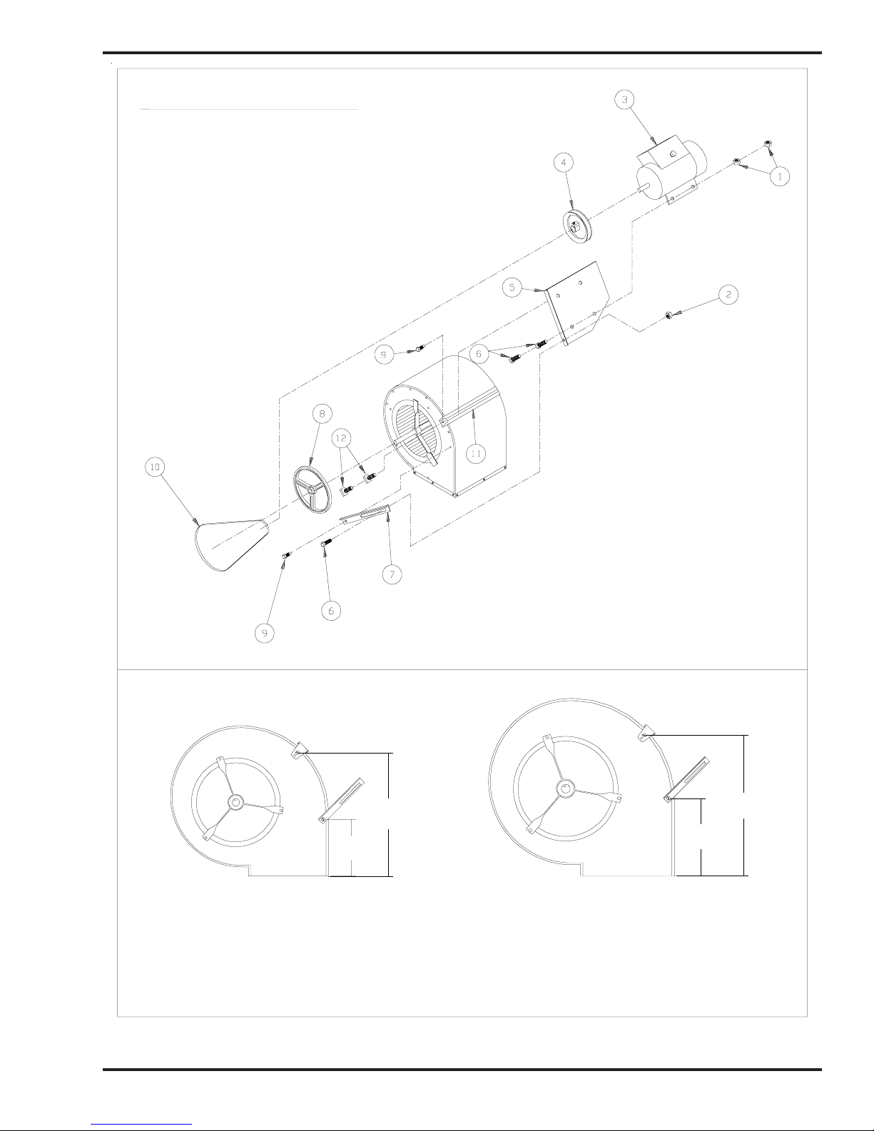
BLOWER ASSEMBLY PARTS LIST
1 NUT
2 NUT
3 2 HP MOTOR
4 MOTOR PULLEY
5 MOTOR MOUNTING PLATE
6 BOLT
7 MOTOR TENSIONING BRACKET
8 BLOWER PULLEY
9 SELF−TAPPING BOLT
10 V−BELT
11 MOTOR MOUNTING BRACKET
12 SQUARE HEAD BOLT
CB−3500 BLOWER CB−5000 BLOWER
NOTE: The brackets must be installed at the correct position on the side of the blower as shown here.
Note the measurements provided which should aid your positioning of the brackets.
Figure 3C - Expanded View of Blower Assembly
18.5"
46.5 cm
8.5"
22 cm
DETAIL OF BRACKET INSTALLATION
3-5
21"
53 cm
11.5"
29 cm
I88289
Operator's Manual: Models CB-3500 and CB-5000 (230 V / 50 Hz)
Installing the Blower Components (continued)
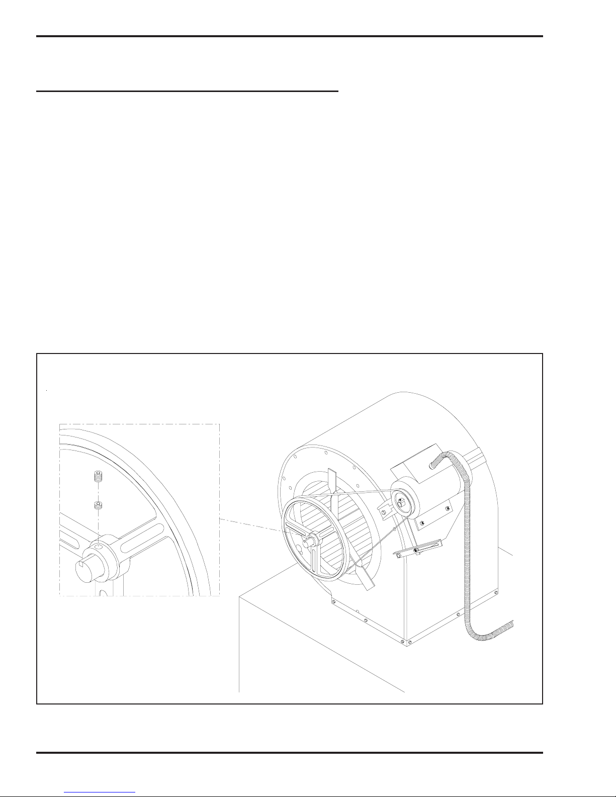
Installing the Motor Pulley, Blower Pulley, and V-Belt
1. Refer to Figures 3C and 3D.
2. Slide the pulleys into position on the motor and blower shafts. ATTENTION: Make sure that
the face of the motor is flush with the side of the blower. Then position the motor pulley 3 cm
(1-1/8") out from the face of the motor. Failure to properly position the motor and the motor
pulley may cause damage to the motor or blower bearings. Now tighten the locking screw in the
motor pulley hub.
3. Position the key in the slot on the motor shaft. ATTENTION: Use a straight edge to make sure
the blower pulley is aligned with the motor pulley, or vibration and bearing damage may occur.
4. Install the double set of locking screws on the blower pulley. (Install the smaller locking screw
and tighten it firmly; then install the second locking screw and tighten it firmly.) It is important
to install both locking screws to prevent the locking screws from working loose.
5. Install the V-belt on the motor pulley and the blower pulley.
6. To tension the V-belt, lift up on the end of the motor mounting plate. Firmly tighten the nut and
bolt on the tensioning bracket.
7. Check that there is a 2 cm (3/4") deflection in the tensioned V-belt. DO NOT overtension the V-belt.
Repeat step #6 if necessary to achieve the proper tension on the V-belt.
NOTE: If you ever need to remove the blower wheel, you must remove both locking screws.
Figure 3D - Blower Assembly Installed on Furnace Cabinet
I88290
3-6
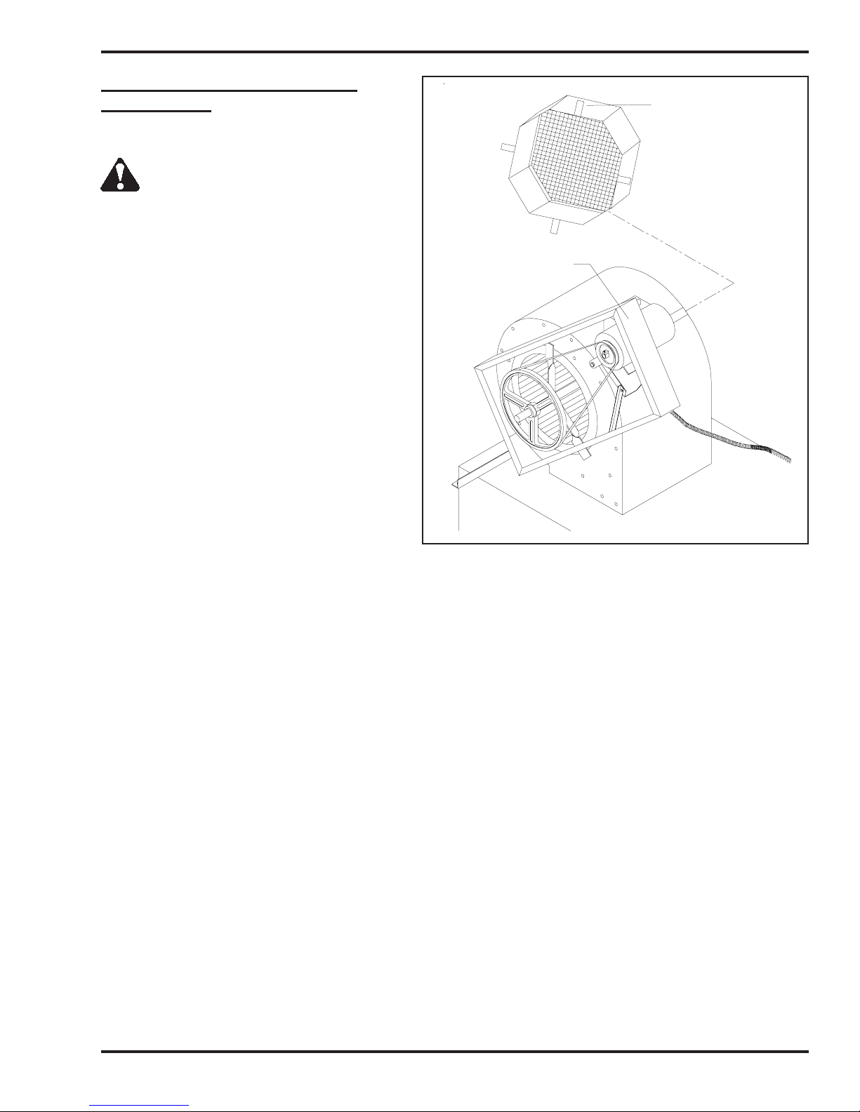
Operator's Manual: Models CB-3500 and CB-5000 (230 V / 50 Hz)
Installing the Belt Guard and the
Blower Guard
WARNING: To prevent serious
personal injury, DO NOT operate the
furnace without the belt and blower guards in
place.
BLOWER GUARD
1. Refer to Figure 3E.
2. Install the belt guard and blower guard as
shown.
BELT GUARD
I88802−A
Figure 3E - Installing the Belt and Blower Guards
3-7
Operator's Manual: Models CB-3500 and CB-5000 (230 V / 50 Hz)
Installing the Hot Air Discharge Components
Determining the Air Discharge Configuration
The CB-3500 and CB-5000 furnaces may be configured for use as EITHER a Unit Heater or a Central
Furnace as described below.
(1) Unit Heater Furnace with blower for FREE AIR applications.
HOT AIR DISCHARGE: Louver assembly (components supplied)
NOTE: If the peak of your shop roof/ceiling is 4.3 m (14') or higher, install
industrial-size ceiling fans to aid in efficient, even heat distribution. A minimum
of one 1.4 m (56") Blade Industrial Ceiling Fan or equivalent is recommended
for each 186 m2 (2000 ft2)of shop space.
Be sure to adhere to the specified clearances as stated in Section 4 of this
manual.
(2)
Central Furnace Furnace with blower for DUCTING applications from 0.06 kPa
(0.25" WC) to 0.10 kPa (0.40" WC) static pressure.*
HOT AIR DISCHARGE: Ductwork (Refer to the following chart for the
proper air discharge/ducting specifications; installation to be accomplished by
HVAC professionals ONLY.)
Be sure to adhere to the specified clearances as stated in Section 4 of this
manual.
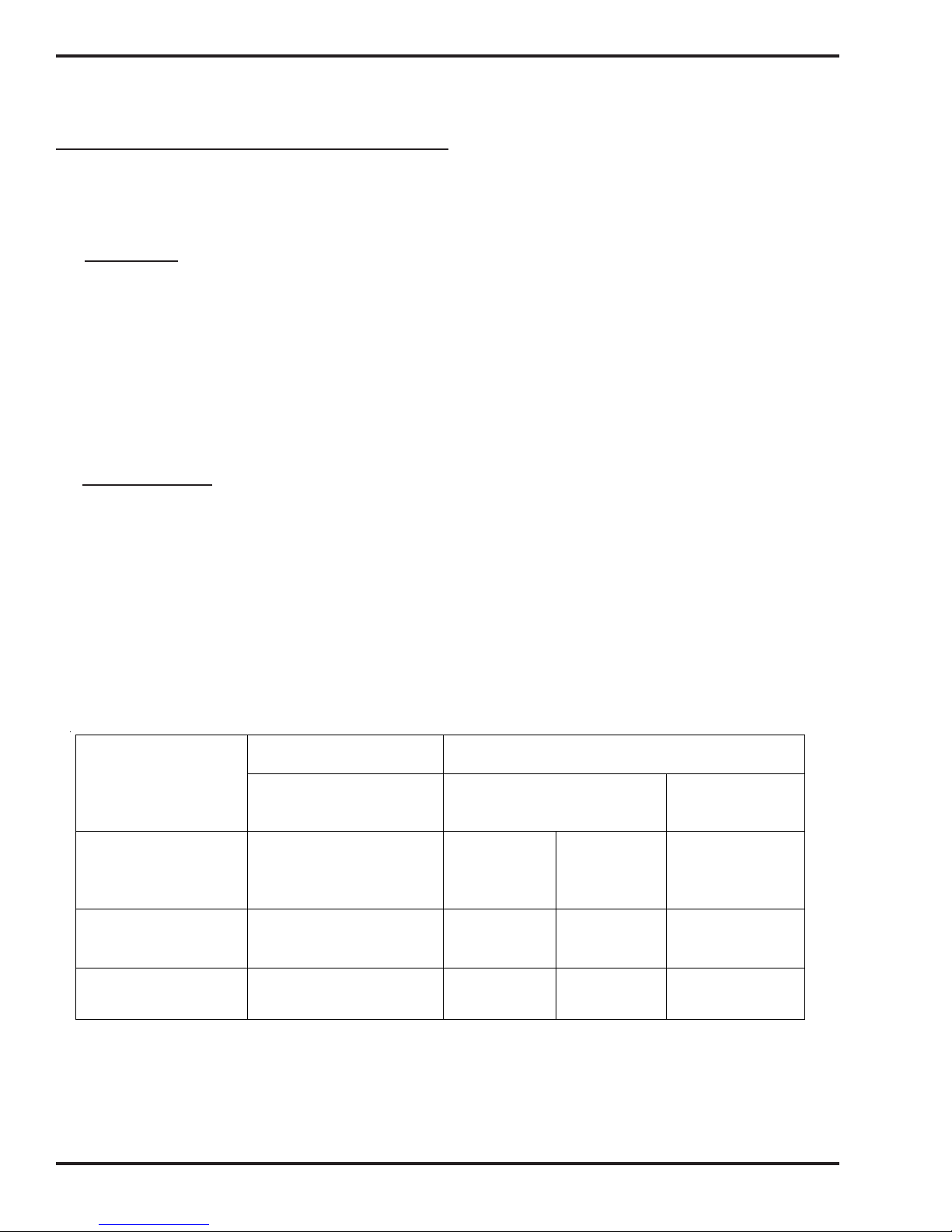
Air Flow - Cubic Meters per Minute (CMM) or Cubic Feet per Minute (CFM)
and Static Pressure (SP) Specifications
PARAMETER
Static Pressure
kPa in Outlet
(Inches WC in Outlet)
CB-3500 CMM
(CB-3500 CFM)
CB-5000 CMM
(CB-5000 CFM)
ATTENTION: A qualified electrician must check the blower motor amperage during operation of the furnace to ensure that
motor amperage does not exceed 85% of the maximum amperage on the motor label. DO NOT operate the blower motor above
85% of maximum amperage or motor damage may occur.
UNIT HEATER
Louver Assembly
(orifice plate insta lled)
Free Air* 0.06 kPa*
119
(4200)
156
(5500)
CENTRAL FURNACE
Ductwork
(orifice plate removed)
0.10 kPa*
(0.25)
113
(4000)
147
(5200)
(0.40)
110
(3900)
144
(5100)
Opening Size
(for ductwork)
N/A
51cm x 51cm
(20" x 20")
61cm x 61cm
(24" x 24")
3-8
Operator's Manual: Models CB-3500 and CB-5000 (230 V / 50 Hz)
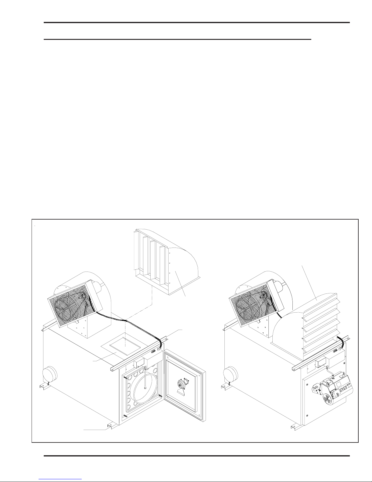
UNIT HEATER APPLICATIONS: Installing the Air Discharge Louver Assembly
The body of the air discharge louver assembly is shipped assembled and is packed on top of the furnace
cabinet. The louvers, nuts and bolts, which must be assembled separately, are packed inside the combustion
chamber.
It is very important to install the air discharge to direct the flow of the hot air from the furnace as desired for
your application. As you will note from Figure 3F, the air discharge may be installed facing forward (as shown)
o
or rotated 90
to the left or right. Additionally, the louvers may be installed horizontally or vertically to direct the
flow of the heated air.
1. Position the body of the air discharge as desired over the hot air outlet on the furnace (i.e. facing
forward, right, or left).
ATTENTION: KEEP THE ORIFICE PLATE IN PLACE (as shown in Figure 3F) when installing
the louver assembly. The orifice plate is necessary for proper air flow from the furnace.
2. Use the 12 self-tapping screws to securely attach the body of the louver assembly to the furnace
cabinet.
3. Install the louvers in the desired position (i.e. horizontally or vertically) using the bolts and locking nuts
provided.
ATTENTION: DO NOT restrict the flow of hot air from the furnace by closing the louvers, or
damage to the furnace and/or blower motor may occur.
ORIFICE
MOUNTING
BRACKET
PLATE
AIR DISCHARGE WITH
LOUVERS MOUNTED
VERTICALLY
STABILIZER
BRACKET
AIR DISCHARGE WITH
LOUVERS MOUNTED
HORIZONTALLY
W
3
s
z
0
1
H
0
s
6
t
0
5
0
4
-
2
0
2
2
s
s
o
f
4
n
6
a
O
D
6
H
3
0
B
7
e
H
p
7
y
5
T
0
.
r
N
I88916
Figure 3F - Installation of the Hot Air Discharge Louver Assembly
3-9

Operator's Manual: Models CB-3500 and CB-5000 (230 V / 50 Hz)
CENTRAL FURNACE APPLICATIONS: Installing Ductwork
If you plan to install ductwork on your furnace, it is mandatory that qualified HVAC personnel design
and install the ductwork system to the Air Flow and SP specifications provided in this manual.
Establish correct duct size according to the following specifications and use radial bends or turning vanes to
allow for proper air flow.
Sizing the Ductwork:
• For Model CB-3500, the outlet on the air discharge is 51 cm x 51 cm (20" x 20"). The main
duct on a CB-3500 must initially maintain an outlet size of 51 cm x 51 cm (20" x 20").
• For Model CB-5000, the outlet on the air discharge is 61 cm x 61 cm (24" x 24"). The main
duct on a CB-5000 must initially maintain an outlet size of 61 cm x 61 cm (24" x 24").
Additionally, to ensure proper air flow from the furnace and to prevent damage to related furnace components,
adhere to the following guidelines for installing ductwork with your CB-3500 or CB-5000 central furnace
application.
Installation Guidelines for Ductwork:
• It is essential that qualified HVAC personnel properly design the ductwork for your
furnace and determine the static pressure for your ducting application;
ATTENTION: Failure to adhere to the static pressure and Air Flow specifications provided in this
manual may result in damage to the blower motor.
• The ductwork should be installed directly over the opening in the top of the furnace cabinet (i.e.
where the louver assembly would be installed for free air applications.)
• THE ORIFICE PLATE MUST BE REMOVED for all ductwork applications.
• Existing ductwork at your installation site may NOT be appropriate or meet the specifications for
your furnace installation.
Installing the Ceramic Target
Installing the Ceramic Target on the Combustion Chamber
ATTENTION: DO NOT fire your furnace without the flame target in place, or combustion chamber
damage will occur. The target is high-temperature ceramic--handle it carefully to avoid damage.
1. Refer to Figure 3A at the beginning of this section to review the proper positioning of the target.
2. Swing open the clean-out door on the furnace front to gain access to the combustion chamber.
3. Use a long rod to support the ceramic target as you guide it into position on the back of the
combustion chamber. The eye bolt on the back of the target fits over the hook on the target
mounting bracket which is located on the back of the combustion chamber.
Closing the Furnace Door
1. After the ceramic target has been installed, close the furnace clean-out door.
2. Tighten the four (4) lock-down nuts in a criss-cross pattern until all are snug.
3-10

Operator's Manual: Models CB-3500 and CB-5000 (230 V / 50 Hz)
Installing the Burner
Checking the Burner Nozzle and Electrodes
NOTE: The burner nozzle is factory installed. Model CB-3500 uses a Delavan 9-5 nozzle. Model
CB-5000 uses a Delavan 9-11 nozzle. The nozzle size is indicated on the nozzle head as shown in
Figure 3G. Refer also to Appendix A at the back of the manual for additional specifications/instructions on the
burner nozzle.
NOTE: Check the electrode settings as specified in Figure 3G. The electrode settings must be correct for
your burner to operate properly.
NOZZLE IS STAMPED
9−5 OR 9−11 ON FLAT
OF NOZZLE HEAD
5 mm
(3/16")
3 mm
(1/8")
NOZZLE
ELECTRODE
NOZZLE ADAPTER
3mm (1/8") SPARK GAP
OUTLINE OF RETENTION HEAD
Figure 3G - Burner Nozzle and Electrode Specifications
NOZZLE TO BE AHEAD OF
RETENTION HEAD BY 3 mm (1/8")
3-11
I88757

Operator's Manual: Models CB-3500 and CB-5000 (230 V / 50 Hz)
Installing the Burner (continued)
Mounting the Burner on the Hinge Bracket
ATTENTION: Burner tube components (e.g. electrodes and retention head) are factory set. Handle the
burner with extreme care so that burner components are not damaged.
1. Remove the nut from the mounting flange of the furnace cabinet, and set it aside for later use.
2. Lift the burner into position so that it is mounted on the hinge bracket on the furnace cabinet.
3. Carefully swing the burner so the retention head enters the throat of the furnace.
4. Check the clearance between the retention head and the furnace throat. There must be at least
3 mm (1/8") clearance, so the retention head is not "bumped" as you swing the burner into
firing position.
NOTE: If the retention head "bumps" the furnace throat, adjust the hinge bracket bolts
as follows:
• While supporting the burner, slightly loosen the two (2) hinge bracket bolts.
• Carefully re-position the burner so it swings freely into its firing position.
• With the burner in its firing position, re-tighten the hinge bracket bolts.
3-12
 Loading...