


FILTERSCAN®
Reference Guide
Version 2.4
The information contained herein is proprietary and is not to be used for purposes other than as an aid in the
operation and/or maintenance of the of the product described herein and is not to be released or reproduced by
anyone without the written permission of CleanAlert, LLC.
Due to CleanAlert's constant strive for product improvement, minor discrepancies between the actual product, text
and illustrations may exist. All information contained herein is based on the latest specifications at the time of
publication and is subject to change without notice.
FILTERSCAN
®
is a registered trademark of CleanAlert, LLC.

Contents
Introduction ………………..…………………….………………………………………………………… 1
In The Box ..............................…………………………………………………………………………. 1
Tools Required ............…………………………………………………………………………………. 1
Safety ………………….…………………………………………………………………………………. 1
Application ………….……………………………............................................................................. 1
FCC Compliance ……………..………………………………………………………………………….. 1
IC Compliance ………………..………………………………………………………………………….. 2
Monitor Installation …………………..……………………..……………………………………. 2
Receiver Installation ……………..…………………………..……………………………………. 5
Operation …………………..……………….……………………………………………………………….. 7
System Monitoring ……….……………………………………………………………….…………….. 7
Alarm Modes ………..………………..………………………….……………………………………… 7
Clogged Air Filter …………...……….………………………………………………………………….. 7
Low battery ………………..…………………………..…………………………………………………. 7
Malfunction ……………..………………………………………………………………………..………. 7
Calibrating When Installing a New Air Filter ………………….………………………………………. 8
Automatic Adjustment ………….………………………….……………………………………………. 8
Specifications …………….…….…………………………………………………………………………… 8
Warranty ……………..……………………………………………………………………………………… 9
Wireless Option ……….………………….………….…………………………………..………………… 9
Transmitter ……………….……………………………………………………………………………… 9
Receiver ………………………………………………………………………………………………… 9
Learn Mode ………………………….…………………………….…………………………………….. 9
Low Battery Indicator …….…………..………………………………………………………………… 10
Identification Address …….…………………………………………………………………………….. 10
Revision History ………………....……………………………………………………………………… 10
Appendix ………………..…………..………………………….……………………………………. 11
Glossary ……………………………..……………..…………………………………………………….. 11
Indicators ………….…………………………..…………………………………………………………. 11
Battery Replacement ……..….……..……………………….………………………………………….. 11
Alarm Indications ………….………………………………..…………………………………………… 12
Disclaimer ……………………….……………….………………………………………………………. 12

Introduction
In The Box 1. FILTERSCAN
Tools Required 1. Drill
Safety WARNING! READ AND UNDERSTAND ALL INSTRUCTIONS. Failure to
Application FILTERSCAN
If the wireless option has been installed, the FILTERSCAN® Monitor will
FCC Compliance This device complies with Part 15 of the FCC Rules. Operation is subject to the
Congratulations on your purchase of the CleanAlert FILTERSCAN® Air
Filter Clog Detection System. The CleanAlert FILTERSCAN® is
intended for continuous and automatic monitoring of the clogging of an air
filter installed into a household or commercial forced air heating, air
conditioning, or heat pump system. Please read all instructions carefully to
insure years of trouble-free operation. We're sure you enjoy outstanding
performance when the FILTERSCAN® is installed by a qualified HVAC
technician and properly operated.
®
Monitor
2. 4 "AA" Batteries (“B” models only)
3. Installation and Operation Guide
4. Template for attaching the FILTERSCAN
®
Monitor to an air duct
5. Mounting Screws
6. Packaging / box
7. External wall adapter power supply – Optional (“B” models only)
8. FILTERSCAN
®
Receiver – Optional (“W” models only)
9. 2 “AAA” Batteries (Receiver only)
2. 7/64” drill bit
3. 3/8” drill bit
4. Phillips Screwdriver
5. ½” drill bit (if Model CA-4DP Differential Pressure kit ordered)
follow all instructions may result in electrical shock and or serious personal
injury.
®
designed to monitor the amount of dirt building on an air filter and alert the
user when the amount of clogging reaches a pre-determined threshold.
The FILTERSCAN® Monitor is compatible with most air filters ranging in
differential pressure drop from 0.10”wg to 4.0”wg and with single or multispeed blowers, but not compatible with VAV (Variable Air Volume)
systems.
transmit alarm conditions to a remote Receiver. The Receiver may be
located up to 100 feet from the Monitor depending upon line-of-sight and
obstacles located between the Monitor and Receiver.
following two conditions: (1) this device may not cause harmful interference, and
(2) this device must accept any interference received, including interference that
may cause undesired operation.
is an air filter clogging detection system. It has been
Formatted: Indent: Left: 1.94", Hanging:
0.28", Outline numbered + Level: 2 +
Numbering Style: 1, 2, 3, … + Start at: 2 +
Alignment: Left + Aligned at: 0.25" + Tab
after: 0.5" + Indent at: 0.5", Tab stops: Not at
0.5"
Formatted: Indent: Left: 1.94", Hanging:
0.28", Outline numbered + Level: 2 +
Numbering Style: 1, 2, 3, … + Start at: 2 +
Alignment: Left + Aligned at: 0.25" + Tab
after: 0.5" + Indent at: 0.5", Tab stops: Not at
0.5"
1

NOTE: This equipment has been tested and found to comply with the limits for a
Class B digital device, pursuant to Part 15 of the FCC Rules. These limits are
designed to provide reasonable protection against harmful interference in a
residential installation. This equipment generates, uses and can radiate radio
frequency energy and, if not installed and used in accordance with the
instructions, may cause harmful interference to radio communications. However,
there is no guarantee that interference will not occur in a particular installation. If
this equipment does cause harmful interference to radio or television reception,
which can be determined by turning the equipment off and on, the user is
encouraged to try to correct the interference by one or more of the following
measures:
-- Reorient or relocate the receiving antenna.
-- Increase the separation between the equipment and the receiver.
-- Connect the equipment into an outlet on a circuit different from that to which the
receiver is connected.
-- Consult the dealer or an experienced radio/TV technician for help.
Changes or modifications not expressly approved by the party responsible for
compliance could void the user’s authority to operate the equipment.
FCC ID Number: AUPFS-242
IC Compliance This Class B digital apparatus complies with Canadian ICES-003.
Model: FS-242-BW Modèle: FS-242-BW
Cet appareil numérique de la classe B est conforme à la norme NMB-003 du
Canada.
This device complies with Industry Canada license-exempt RSS standard(s).
Operation is subject to the following two conditions: (1) this device may not cause
interference, and (2) this device must accept any interference, including
interference that may cause undesired operation of the device.
Cet appareil est conforme à Industrie Canada exempts de licence RSS norme.
Opération est soumis aux deux conditions suivantes: (1) cet appareil ne peut pas
causer de brouillage et (2) cet appareil doit accepter toute interférence, y compris
les interférences pouvant causer un fonctionnement intempestif du dispositif.
Model: FS-242-CW Modèle: FS-242-CW
IC Certification/Registration Number IC: 10341A-FS242
Numéro de Certification / d'enregistrement les IC: 10341A-FS242
Monitor Installation
Although the CleanAlert FILTERSCAN® Air Filter Clogging Monitor and
Alarm, Model FS-242, may be installed upstream, downstream, or
differentially across the air filter (using optional tubing kit Model CA-4DP),
the best results will be found when installing downstream of the air filter
(that is, between the air filter and the system blower fan, usually located at
the return duct of the HVAC system).
WARNING! Ensure that the HVAC system blower motor/fan is turned OFF
until told to otherwise!
1. The FILTERSCAN® Monitor is to be attached to the external wall of
the air duct, either upstream or downstream from the air filter to be
Formatted: Indent: Left: 1.97", Outline
numbered + Level: 2 + Numbering Style: 1, 2,
3, … + Start at: 1 + Alignment: Left + Aligned
at: 2.08" + Tab after: 2.33" + Indent at:
2.33"
2

monitored. NOTE: The minimum distance for positioning the
FILTERSCAN
®
Monitor from the air filter is six (6) inches.
2. Locate an area on the return duct, preferably downstream from the air
filter (that is, between the air filter and the system blower), large
enough to place the Monitor template on a flat surface and where
there are NO obstacles inside the duct. There should be sufficient
clearance from the surrounding walls and from any components of the
air supply system.
3. Place the Monitor template at the location found in the previous step,
such that "TOP" is facing upward. NOTE: The FILTERSCAN®
Monitor front panel must be clearly visible when installed.
4. Using the template, drill one large hole, (3/8") for the sensor and four
small holes (7/64") for the mounting screws.
5. Attach the FILTERSCAN® Monitor by aligning its sensor tube with
the larger hole and secure the Housing using the mounting screws
supplied. The sensor tube does not extend into the duct.
6. Set the Upstream/Downstream switch so that it matches the
FILTERSCAN
®
Monitor position with respect to the air filter (that is,
OFF for upstream mounting or ON for downstream or differential
mounting). The switch can be accessed by removing the front cover
of the Monitor.
Formatted: Indent: Left: 1.97", Outline
numbered + Level: 2 + Numbering Style: 1, 2,
3, … + Start at: 1 + Alignment: Left + Aligned
at: 2.08" + Tab after: 2.33" + Indent at:
2.33"
3

Power Receptacle
7. Apply power:
a. Models FS-242-B and FS-242-BW - Insert the wall mount power
adapter into the FILTERSCAN® power receptacle, or install 4 AA
batteries and replace the Monitor front cover. See Appendix for
battery replacement.
Formatted: Indent: Left: 1.97", Outline
numbered + Level: 2 + Numbering Style: 1, 2,
3, … + Start at: 1 + Alignment: Left + Aligned
at: 2.08" + Tab after: 2.33" + Indent at:
2.33"
b. Models FS-242-C and FS-242-CW – These models should be
installed by a qualified electrician, and are powered from the HVAC
systems auxiliary 24 VAC/DC power supply. A typical installation
will have that power run through rigid conduit to the
FILTERSCAN
®
.
c. The STATUS LED should come on green momentarily then turn
and remain red. This indicates that the unit has not yet been
calibrated to the air filter and HVAC system upon which it is
installed.
4

8. Wait for approximately 15 seconds (warm up and stabilization time).
9. Install a clean, new air filter into the HVAC system.
10. Depress the ZERO/CLEAN button ONCE. The STATUS LED will
blink yellow for several seconds while the FILTERSCAN® records
the system’s FAN OFF condition, then turn to blinking green. This
Formatted: Indent: Left: 1.97", Outline
numbered + Level: 2 + Numbering Style: 1, 2,
3, … + Start at: 1 + Alignment: Left + Aligned
at: 2.08" + Tab after: 2.33" + Indent at:
2.33"
indicates proper operation and that you are ready to move to next
step. If the unit detects the zero air flow is out of limits, the STATUS
LED will blink red. In this case, check to see that the HVAC system
blower fan is OFF and no conditions exist during this part of the
calibration that would cause air to be moving within the HVAC ducts,
such as opening and closing of doors or windows. If no such
condition exists, contact the company that you purchased the
FILTERSCAN
®
from for repair information.
11. Adjust the thermostat temperature adjustment to either increase or
decrease the room temperature by at least four degrees, enough to
signal the HVAC system to turn on heating or cooling.
12. Once the HVAC system blower fan turns on, wait one minute for the
blower fan to stabilize.
13. Depress the ZERO/CLEAN button once. The STATUS LED should
turn from blinking green to blinking yellow for several minutes. This
indicates that the unit is calibrating itself to the air filter and HVAC
system into which it is installed. Once calibration is completed, the
STATUS LED will blink green a few times then turn off.
14. Return the thermostat to normal operating temperature. This
concludes the installation of the FILTERSCAN® Monitor.
15. The SERVICE FILTER control is a fine tuning adjustment that has
been calibrated to the mid-range, Recommended Setting at the
factory. This control allows the user to change the point at which the
clog alarm will be triggered. Turning the SERVICE FILTER adjustment
clockwise will cause the FILTERSCAN® to issue an alarm at a lower
level of filter clogging. Turning the SERVICE FILTER adjustment
counter-clockwise will cause the FILTERSCAN® to issue an alarm at a
higher level of filter clogging.
Receiver Installation – Wireless Option Only
1. Remove the front cover of the Receiver by depressing the latch at the
top of the Receiver housing, rotating the front cover downward, and
lifting the front cover out of the housing.
Formatted: Indent: Left: 1.97", Numbered +
Level: 1 + Numbering Style: 1, 2, 3, … + Start
at: 1 + Alignment: Left + Aligned at: 0.03" +
Tab after: 0.28" + Indent at: 0.28", Tab stops:
Not at 0.28"
5

2. Install two AAA batteries.
3. Your FILTERSCAN® Monitor and Receiver have been paired
(matched) at the time of manufacturing and should require no further
attention.
4. To test the pairing of the Monitor and Receiver:
a. Monitor and Receiver should be turned on and in close proximity to
Formatted: Indent: Left: 1.97", Numbered +
Level: 1 + Numbering Style: 1, 2, 3, … + Start
at: 1 + Alignment: Left + Aligned at: 0.03" +
Tab after: 0.28" + Indent at: 0.28", Tab stops:
Not at 0.28"
Formatted: Indent: Left: 1.97", Numbered +
Level: 1 + Numbering Style: 1, 2, 3, … + Start
at: 1 + Alignment: Left + Aligned at: 0.03" +
Tab after: 0.28" + Indent at: 0.28", Tab stops:
Not at 0.28"
each other.
b. Test the Receiver by inserting a paperclip through the small hole in
the front cover of the Receiver until the click of a switch is felt, then
immediately pressing the SEND button on the Monitor. This
transmits a signal to the Receiver, which turns on the Red LED
and Beeper.
5. To insure proper operation when Receiver is placed in a desired
remote location, retest the Receiver as described above. This remote
procedure may require two people.
Formatted: Indent: Left: 1.97", Numbered +
Level: 1 + Numbering Style: 1, 2, 3, … + Start
at: 1 + Alignment: Left + Aligned at: 0.03" +
Tab after: 0.28" + Indent at: 0.28", Tab stops:
0.25", List tab + Not at 0.28"
6

NOTE: Although the wireless transmission range is up to 100 feet,
it is greatest with no obstructions between the Monitor (transmitter)
and Receiver. Any obstructions, such as walls, floors, and ceilings
will reduce the range of transmission, and relocation of the
Receiver may be required. Retest with each location to ensure
proper operation
6. Mount the Receiver vertically by using the screws or adhesive strip
supplied.
7. Install the front cover by placing the bottom flanges into the housing
and rotating the cover upward until the top latches into the housing.
Operation
System Monitoring The STATUS LED will blink green approximately once per minute (called a
NOTE: Should there be a power failure the FILTERSCAN® will save all
Alarm Modes The FILTERSCAN
NOTE: The HVAC system blower fan must be running when the
Clogged Air Filter When the FILTERSCAN
Low Battery When the FILTERSCAN
Malfunction When the FILTERSCAN
heartbeat) to indicate that the unit is functioning properly. Usually the
FILTERSCAN
®
will be in the standby mode, conserving power. It wakes
up periodically to monitor air filter condition, battery level, and system
operation. If no alarm conditions are detected, the FILTERSCAN® goes
back to sleep after several minutes of monitoring.
parameters such as the clean air filter calibration and the current state of
the air filter. When power is restored, the FILTERSCAN® Monitor will
continue operation with no user action required. The same applies when
replacing depleted batteries.
®
provides both audible and or visual alarms indicating
a clogged air filter, a low battery, or a system malfunction. There is also a
wireless option which allows remote monitoring of system conditions.
FILTERSCAN
FILTERSCAN
®
Monitor attempts to check air filter condition. Since the
®
Monitor checks the air filter condition periodically, it may
take several days to detect, trigger, and alarm a clogged filter condition.
®
detects a clogged air filter, an alarm condition
is triggered. The red STATUS LED will illuminate, blinking five times
approximately every ten minutes until the alarm condition is reset. There
will also be an audio alert which corresponds to the visual alarm indication.
The clogged filter alarm is reset by installing a new, clean air filter,
depressing the CALIBRATE button, and then following the instructions in
the section "Calibrating When Installing a New Air Filter".
NOTE: A new air filter should always be installed whenever the
CALIBRATE operation is performed.
®
detects a low battery condition, an Alarm
condition is triggered. The STATUS LED will blink yellow approximately
once per minute to indicate a low battery in the Monitor. Replacing the
Monitor batteries (see the Appendix for instructions) will reset the alarm
condition.
®
detects an internal malfunction, an alarm
condition is triggered. The red STATUS LED will illuminate continuously
until the malfunction is corrected. In the unlikely event this should occur,
remove power from the FILTERSCAN® by removing the batteries,
Formatted: Indent: Left: 1.97", Numbered +
Level: 1 + Numbering Style: 1, 2, 3, … + Start
at: 1 + Alignment: Left + Aligned at: 0.03" +
Tab after: 0.28" + Indent at: 0.28", Tab stops:
Not at 0.28"
7

unplugging the optional AC Adapter, or in the case of conduit-powered
models (“C”) contacting your HVAC system electrician to have the power
to the Monitor cut. Wait for a minute and restore power. If your
FILTERSCAN
®
unit is operating with both AC Adapter and batteries
installed, both will need to be removed in order to reset the malfunction. If
this does not reset the malfunction alarm, contact the company that you
purchased the FILTERSCAN® from for repair information.
Calibrating When Whenever a new air filter is installed, the FILTERSCAN
®
clog detector
Installing a New Air Filter system must be calibrated. Calibration establishes the clogged air filter
detection threshold based upon the condition recorded for a new air filter.
When a new air filter is installed, its condition is recorded and saved in
nonvolatile memory.
1. Insure that the HVAC system is OFF at the thermostat.
2. Remove the dirty air filter from the HVAC system.
3. Install a new, clean air filter into the HVAC system.
4. Make sure the FILTERSCAN® Monitor power is ON via either AC
Adapter or Battery installation, making sure the low battery indication
is not being displayed.
5. Depress the ZERO/CLEAN button on the FILTERSCAN® Monitor.
6. Wait for the red STATUS LED to illuminate.
7. Depress the ZERO/CLEAN button again.
8. Wait several seconds for the STATUS LED to change from blinking
yellow to blinking green.
9. Turn the HVAC system ON at the system thermostat.
10. Set the thermostat temperature adjustment to either increase or
decrease the room temperature by four degrees, which should be
enough to signal the HVAC system to turn heating or cooling on.
11. Wait one minute for the HVAC system blower fan to turn on and
stabilize.
12. Depress the ZERO/CLEAN button again.
13. Wait several minutes for the STATUS LED to turn from blinking yellow
to blinking green. During this time, the unit is recording the condition
of a clean air filter.
14. Wait several seconds for the blinking green STATUS LED to turn
OFF.
15. Return the thermostat to normal operating temperature.
Your FILTERSCAN® Monitor is now calibrated to the type of air filter you
have installed. Depending on the air filter type and manufacturing
tolerances, you may need to calibrate the FILTERSCAN® air filter
clogging detector each time a new air filter is installed.
Automatic Adjustment ATTENTION - HVAC systems with two-speed blowers! Typical HVAC
systems will have different blower speeds for Heat and A/C. The
FILTERSCAN
blower speeds.
®
Monitor automatically adapts to the changes in HVAC
Formatted: Indent: Left: 1.97", Numbered +
Level: 1 + Numbering Style: 1, 2, 3, … + Start
at: 1 + Alignment: Left + Aligned at: 0.25" +
Tab after: 0.5" + Indent at: 0.5", Tab stops:
Not at 0.5"
Specifications
Pressure Differential Range 0.1 to 4.0 in H2O
Clog Filter Trigger Point 1.5 to 2 times initial differential pressure (at the recommended setting
on the SERVICE FILTER control)
Temperature Range 32o to +122o F (0o to +50o C) Operating
8

-40o to +257o F (-40o to + 125o C) Storage
Humidity 80% RH, non-condensing
Power Requirements (-B & -BW) 5.5 VDC at 25 mA Status LED on, 3 mA Transmitting, 60 uA Standby
Batteries, Monitor (-B & -BW) (4) AA 2400 mAH
Batteries, Receiver (2) AAA 1100 mAH
Battery Life Approximately 1 year
Power Requirements (-C & -CW) 24 VAC/DC at 25 mA Status LED on, 3 mA Transmitting, 60 uA
Insertion Depth into Duct Does not extend into duct
Clogged Air Filter Alarm Red STATUS LED & 2 KHz Beeper alternating ON & OFF five times
Low Battery Alarm Yellow STATUS LED blinking approximately once per minute
Malfunction Alarm Red STATUS LED continuously illuminated
Mounting 5 holes, 4 @ 7/64” and 1 @ 3/8"
Monitor Dimensions 6” x 4.625” x 1.5”
Receiver Dimensions 2.75” x 3.75” x 1.0”
Wireless Frequency 418 MHz
Transmission Range Up to 100 feet, depending upon line-of-sight and obstacles
FCC Identification # AUPFS-242
Industry Canada # 10341A-FS242
Standby
Warranty
One (1) year limited warranty Please refer to http://www.cleanalert.com/termsofsale.html for full warranty
text.
Wireless Option
Transmitter In a wireless system, the FILTERSCAN
transmitter, operating at a frequency of 418 MHz, which is activated
whenever there is an alarm condition. Transmissions are very short in
Each FILTERSCAN® Monitor is randomly assigned one of over 16
Receiver The FILTERSCAN
Learn Mode Each FILTERSCAN
duration and intermittent until the alarm condition is reset.
million identification addresses at the time of manufacture. This is
important in systems where neighbors have installed similar wireless
systems.
®
operating at a frequency of 418 MHz, which is activated intermittently,
listening for an alarm condition. The Receiver listens for the
FILTERSCAN
transmissions originating from your system’s Monitor. This prevents
inadvertent activation when neighboring buildings also have
FILTERSCAN
FILTERSCAN
system, consisting of a Monitor and a Receiver, has had both components
identification addresses matched at the factory. In the event that a
replacement Receiver is introduced into your system, that Receiver must
learn the system Monitor’s identification address. In order to accomplish
Receiver contains a wireless receiver, also
®
transmitter's identification address and responds only to
®
systems in operation.
®
Receiver has the ability to learn and store a
®
Monitor's identification address. Your FILTERSCAN®
®
Monitor contains a wireless
9

Rev. #
Effective
Summary:
DRAFT
Initial draft for review and validation.
Version 1.1
2/2/12
Initial release for review.
Version 2.0
5/25/12
Initial printing release.
Version 2.1
6/4/12
Added Wireless Installation Section and Power failure statement in the System
Monitoring section. Revised the Indicator section.
Version 2.2
6/6/12
Added Copyright notice. Revised Figures & battery specification.
Version 2.3
6/12/12
Updated per comments, mostly grammar.
Version 2.4
6/13/12
Added Differential Pressure Mounting kit and Tools Required section.
this, both the Receiver and Monitor must be located close to each other.
The steps are:
1. Remove the Receiver front cover.
2. Depress the LEARN button located next to the batteries.
3. Within 5 seconds, depress the SEND button at the Monitor. After
several seconds, the Monitor will beep once. Then, after another
several seconds, the monitor will beep twice.
4. To confirm proper pairing of the Receiver to the Monitor,
a. After mounting the Monitor and Receiver, depress the LISTEN
pushbutton and insert a straightened paper clip through the small
hole located near the bottom of the Receiver cover.
b. Within 5 seconds, depress the SEND pushbutton on the Monitor.
This may require a second person.
c. The Red indicator should illuminate and the Beeper should sound
for approximately five seconds, indicating that the Receiver is
mounted within range of the Monitor.
NOTE: The best transmission range is obtained when a direct line-of-sight
between the Monitor and Receiver exists. Any obstructions, such as floors
and walls, will decrease the operating range of the system, and relocation
of the Receiver may be required.
Low Battery Indicator Receiver: When the FILTERSCAN
®
Receiver detects a low battery
condition, the Receiver's yellow STATUS LED will blink approximately
once per minute.
Monitor: When the FILTERSCAN® Receiver detects a low battery
condition at the Monitor, the Receiver's yellow STATUS LED will blink
three times every minute.
Identification Address Creating an identification address is performed by manually depressing the
SEND button on the Monitor. Wait about ten seconds until the first beep.
Depress the Create Address button on the Monitor. The green LED will
start flashing. After about one second, depress the Create Address button
again. The green LED will turn off. All of these steps must be completed
before the second set of two beeps. NOTE: The Create Address button is
accessible internally in the Monitor and intended only to be used by factory
technicians.
Formatted: Indent: Left: 1.97", Numbered +
Level: 1 + Numbering Style: 1, 2, 3, … + Start
at: 1 + Alignment: Left + Aligned at: 2.22" +
Tab after: 2.47" + Indent at: 2.47", Tab stops:
Not at 2.47"
Revision History
10

Appendix
Glossary
Dirty Air Filter ............... An air filter which has been in use and has collected some amount of dirt
Clogged Air Filter ......... An air filter which has collected a sufficient amount of dirt or dust particles
Monitor ......................... The sensor voltage detection and signal processing portion of the system,
Receiver ....................... The optional portion of the system containing a wireless receiver of data
Address ........................ One of 16 million randomly assigned identification numbers of each
Indicators
Green STATUS LED...... The blinking Green STATUS LED at the FILTERSCAN® Monitor or
Yellow STATUS LED..... The blinking Yellow STATUS LED at the FILTERSCAN® Monitor
Red STATUS LED ........ The Red STATUS LED at the FILTERSCAN® Monitor and Receiver is
Beeper .......................... The audible beeper at the FILTERSCAN® Monitor and Receiver is an
Battery Replacement
Access ......................... Remove the front cover from the FILTERSCAN® Monitor or Receiver
Installation ................... Insert four (4) AA batteries in the battery holder of the FILTERSCAN®
or dust particles that discolor the filter fibers or element but do not
substantially affect the air flow through it.
to not only discolor the filter fibers or element but decrease the air flow
through the filter as well. The FILTERSCAN® typically identifies a filter
as clogged when the differential pressure within an HVAC system
increases to 1.5 to 2 times the initial differential pressure identified when
the unit was calibrated with a clean filter.
which may contain an optional wireless transmitter.
and indicates various alarm conditions.
monitor.
Receiver indicates normal operation.
indicates a process is occurring and can also indicate a low battery
condition at the Monitor or Receiver.
an alarm indicator which blinks whenever an alarm condition occurs.
alarm indicator which beeps whenever certain alarm conditions occurs.
housing. Remove the batteries.
Monitor, or insert two (2) AAA batteries in the battery holder of the
FILTERSCAN
recommends using DURACELL® COPPERTOP batteries.
®
Receiver, and replace the front cover. CleanAlert
11
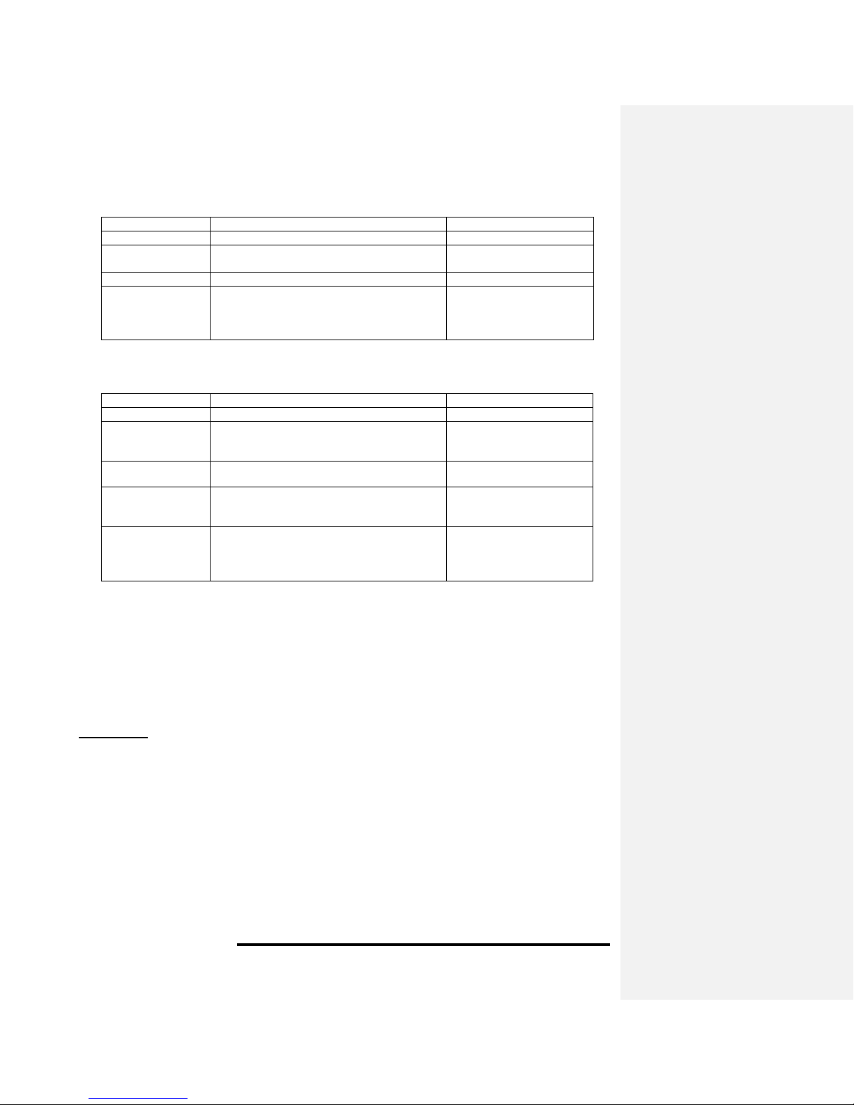
Alarm Condition
Alarm Indication
Clear Alarm Procedure
Normal Operation
STATUS LED flashes green every minute.
None
Clogged Filter
STATUS LED flashes red five times every
ten minutes. Beeper sounds with LED flash.
Replace Filter and
Recalibrate
Low Battery
STATUS LED flashes yellow every minute.
Replace Batteries
Sensor Failure
STATUS LED continuously on red.
Contact the company that
you purchased the
FILTERSCAN
®
from for
repair information
Alarm Condition
Alarm Indication
Clear Alarm Procedure
Normal Operation
STATUS LED flashes green every minute.
None
Clogged Filter
STATUS LED flashes red five times every
ten minutes. Beeper sounds with LED flash.
Supersedes the Heartbeat indication.
Replace Filter and
Recalibrate
Receiver Low
Battery
STATUS LED flashes yellow every minute.
Replace Receiver
Batteries
Transmitter Low
Battery
STATUS LED flashes yellow three times
every minute. Supersedes the Heartbeat
indication.
Replace Transmitter
Batteries
Sensor Failure
STATUS LED continuously on red.
Contact the company that
you purchased the
FILTERSCAN
®
from for
repair information
Alarm Indications
Monitor/Transmitter Alarm Indications
Receiver Alarm Indications
Disclaimer
The data contained herein are furnished for information only and are believed to be reliable. We cannot assume responsibility for
the results obtained by others over whose methods we have no control. It is the user's responsibility to determine suitability for the
user's purpose and to adopt such precautions as may be advisable for the protection of property and of persons. In light of the
foregoing, the warranty of CleanAlert, LLC on this product shall be exclusive and in lieu of any other warranties, including, without
limitation, any warranty of fitness for a particular purpose or warranty of merchantability or any other warranties which may be
claimed to arise by operation of law, custom, trade usage, or course of dealing between CleanAlert, LLC and the customer. In no
event shall CleanAlert, LLC be liable, whether in contract or tort (including negligence) for damages in excess of the purchase price
of the product(s), or for any indirect, incidental, special or consequential damages of any kind, or loss of revenue or profits, or other
financial loss arising out of or in connection with the ability or inability to use the product(s), to the full extent these damages may be
disclaimed by law. The discussion herein of various applications is not to be interpreted as representation that they are free from
domination of patents owned by others or as a license under any CleanAlert, LLC patents that may cover such applications. We
recommend that each prospective user test his proposed application before use, using this data as a guide.
CleanAlert products are manufactured under one or more of the following U.S. Patents: 7,178,410; 7,490,512; and others pending.
Specifications are subject to change without notice.
© 2012 CleanAlert, LLC
12
 Loading...