

Page 1
CLAY & BAILEY MFG. CO.
MODEL 1700 PRESSURE/VACUUM MANWAY
OPERATION & MAINTENANCE
MANUAL
PRODUCT DESCRIPTION
The C & B model 1700 24” PV manway is designed for use on storage tank that
require a large volume of pressure and vacuum relief.
The C & B model 1700 24” PV manway is not a static tank appurtenance, but is
an integral part of the dynamic operation of the tank. Just as other pertinent equipment
to your process, such as blowers, pumps, and valves, this PV manway requires regular
scheduled maintenance inspections.
FREQUENCY OF INSPECTIONS
The frequency of inspections of the model 1700 manway is dependent upon the
environment and operating conditions.
Definitions
Page 2

Mild operating conditions – Vented vapors of internal fluids and outside air that does not
cause a residue to form, or excessive corrosion on working parts of the manway and/or
vapor or gas moving through the manway is constant and no surge shock is
encountered.
Extreme operating condition – Internal vapors, particulate or liquid under operating
conditions that will cause product buildup or corrosion of manway. Pressure or vacuum
surges and shock occurring on areolar basis during operation.
Operating Conditions Number of Inspections/Month
Normal 1
Extreme 2 -4*
*Depending on the rate of buildup or severity of the conditions.
GENERAL INSPECTION PROCEDURE
CAUTION: Pressure or vacuum conditions in the tank must be relieved and
must be in a non-operating state before releasing cams, removing hood or
entering the tank through manhole.
DOME
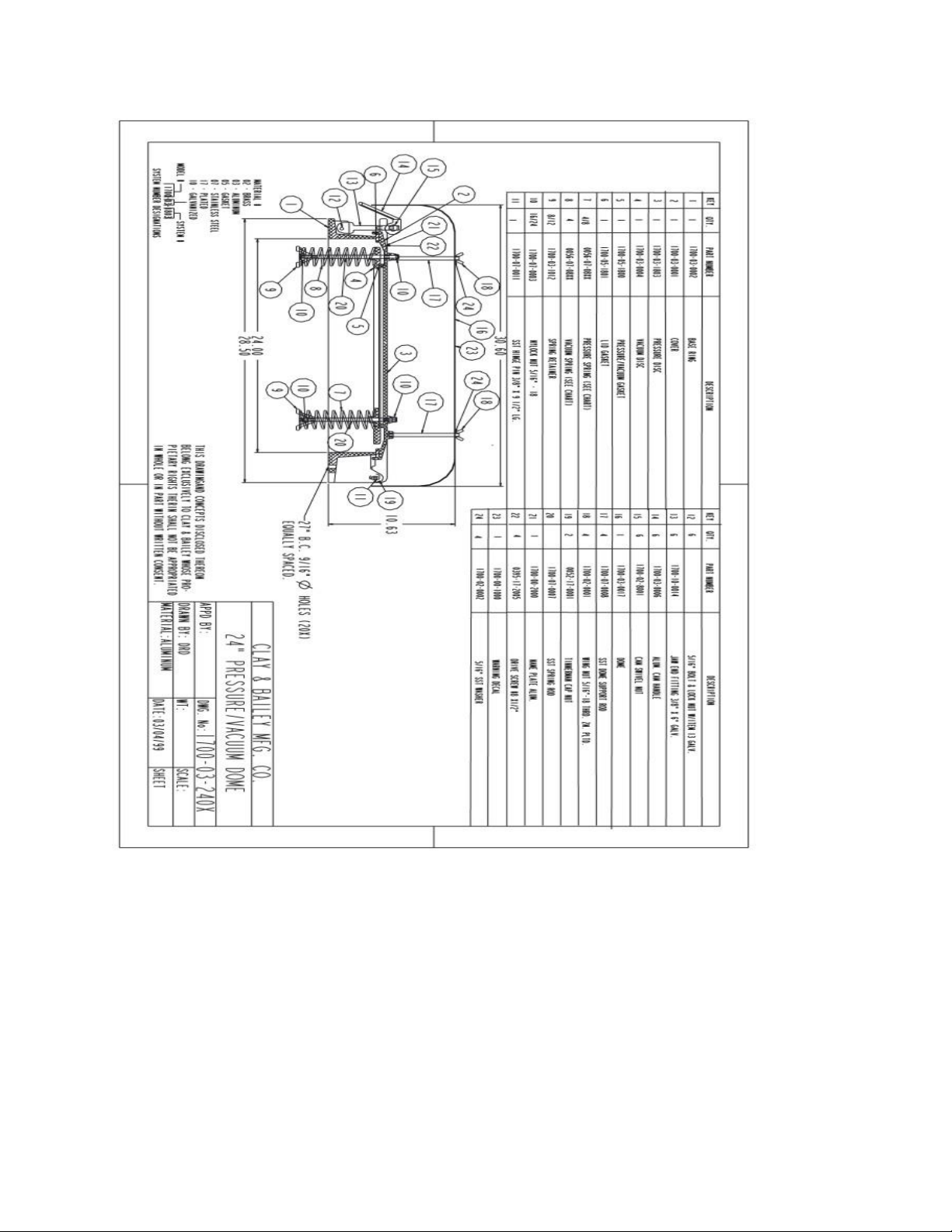
1. Inspect the rain hood dome (16) for holes and damage where moisture may
enter. Replace immediately the dome if damage.
2. Check the dome for excessive dents and distortion that may restrict the flow into
and out of the pressure/vacuum manway.
3. Clean out any product buildup and/or debris around the dome and between the
dome and the manway.
4. Remove the dome from the support rods (17) by removing the nuts (18) on top of
the dome and inspect the rods for straightness and corrosion. Replace any that
2
Page 3
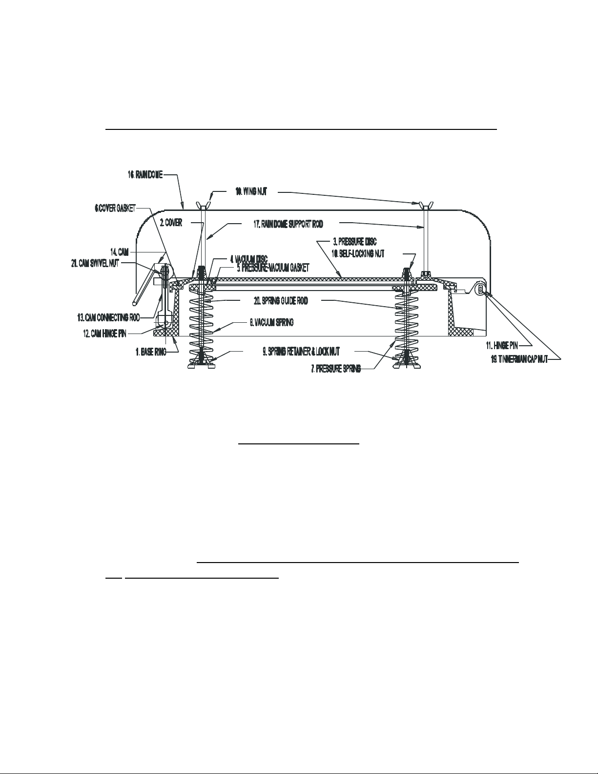
are bent and/or corroded to excessively. All threads are to have threaded locking
fluid on reassembly.
5. Do not reinstall the rain hood until after completing the remaining inspection.
BASE AND COVER
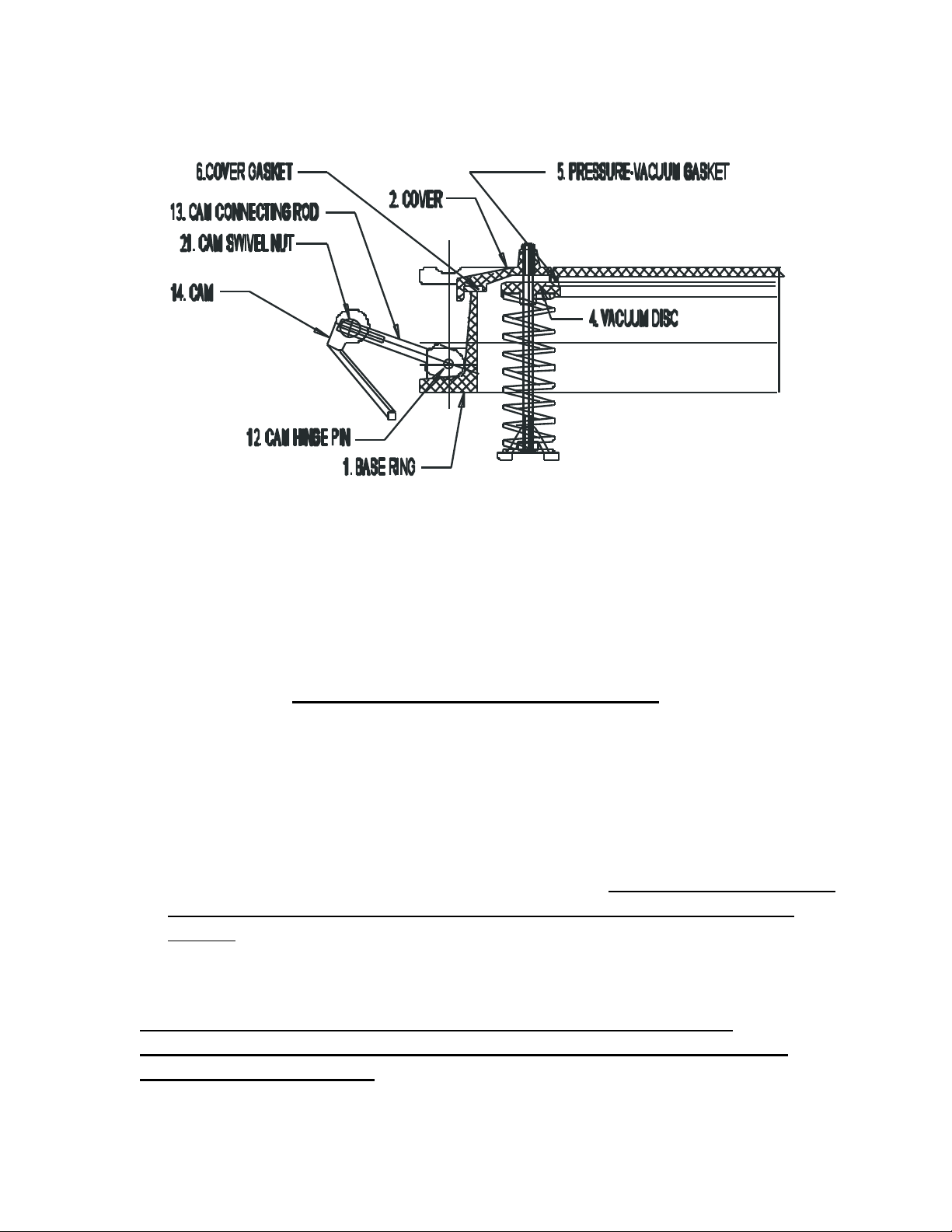
1. Unlock the 6 cams (14) from the cover (2) and lay on the tank away from the
base (1). With both hands on opposite side, move the cover on the base to
determine flatness of the cover fit to the base. There should be only minimal
movement and no rocking should be evident.
2. Lift cover (2) and taking care when laying it back on the tank roof to not damage
the support rods for the rain hood. Inspect the cover gasket (6) for damage and
buildup of product. Some permanent set will eventually occur, but when the
gasket is indented 1/16”, the gasket must be replaced to insure proper cover to
base seal.
3. Inspect base and the cover for corrosion pitting and product buildup and clean all
surfaces. If corrosion is 1/8” deep or out of flatness exceeds 1/16”, the affected
parts need to be replaced at the factory.
3
Page 4
PRESSURE AND VACUUM PLATES
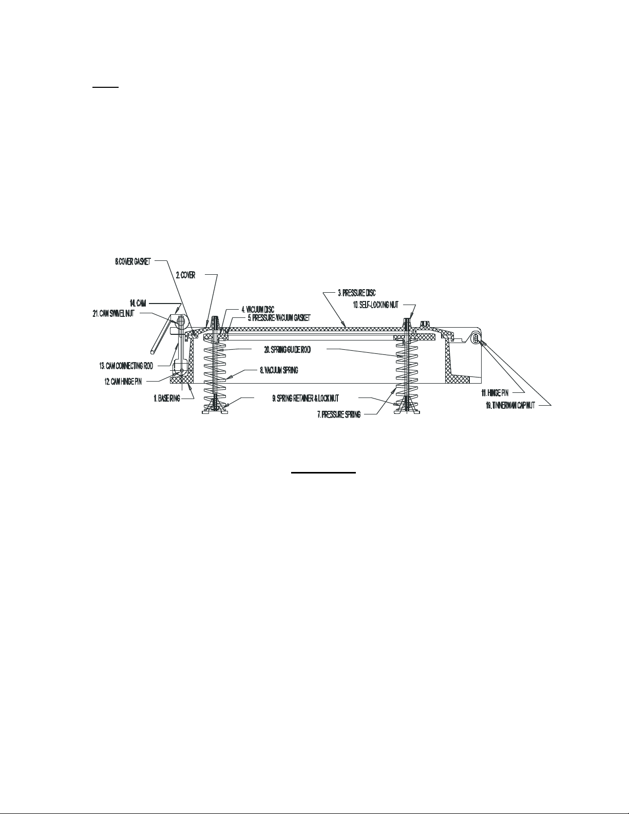
1. This is the functional area of the manway a more detailed inspection is required.
The pressure/vacuum gasket should not show a permanent set of more than a
1/16”. If more wear is evident, it should be sent to the factory for replacement
immediately.
2. Product and foreign material that has coated any surface in the pressure/vacuum
disc area should be removed and clean immediately. If this area is not kept clean
and clear of material may cause the pressure/vacuum area may not operate
properly.
3. Inspect for broken and missing parts, if there is parts missing or broken the unit
should be sent back to the factory for replacement and repair.
CAUTION: DO NOT ADJUST SPRING RETAINERS HEIGHT VIA THE
LOCKNUTS, AS THE SPRINGS ARE FACTORY PRESET AT THE PROPER
PRESSURE AND VACUUM.
4
Page 5
Note: Frequency of cleaning these surfaces is dependent upon the content of the
tank and reaction of venting to atmosphere. (Please to refer to page 2)
4. Spring rods (20) should be inspected for surface condition, straightness and
tightness into the pressure disc (5) and the cover (2). Keep all rods clean to allow
free movement of discs at all time.
5. Check all springs are free from product buildup and verify that all are carrying
load. Measurement from the vacuum disc (4) to spring retainer leg (9) must be
equal for all the pressure springs, (inner springs (7)).
6. For the vacuum spring, (4 outer springs (8)), measure from the vacuum disc (4)
to the spring retainer leg (9).
CAM SET
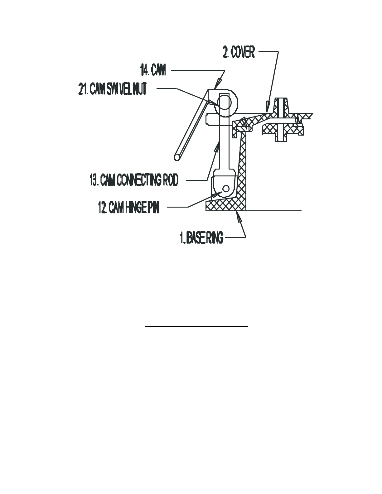
1. Each cam assembly includes the cam (14), cam swivel nut (21), jaw end fitting
(13) and pin (12). Check all part for corrosion, looseness, and thread quality, plus
all pins for consistent fit. When excessive wear and/or corrosion are evident,
parts must be replaced immediately.
2. Test each cam assembly, locked down on the cover (2). Make adjustments with
cam (14) and jaw end fitting (13) to assure equal pressure around the perimeter
of the cover (2) and base (1).
5
Page 6
BEFORE INSTALLATION
I. Inspection of the shipment, examine pressure/vacuum manway for any
shipping damage.
II. Examine the spring assembly on the manway, springs, spring rods and spring
retainer for damage.
6
Page 7
7
 Loading...