

Clavister Wolf W30, Wolf W50 Getting Started Manual

Clavister Wolf W30
Getting Started Guide
Clavister AB
Sjögatan 6J
SE-89160 Örnsköldsvik
SWEDEN
Phone: +46-660-299200
www.clavister.com
Published 2015-06-26
Copyright © 2015 Clavister AB

Clavister Wolf W30
Getting Started Guide
Published 2015-06-26
Copyright © 2015 Clavister AB
Copyright Notice
This publication, including all photographs, illustrations and software, is protected under
international copyright laws, with all rights reserved. Neither this manual, nor any of the material
contained herein, may be reproduced without the written consent of Clavister.
Disclaimer
The information in this document is subject to change without notice. Clavister makes no
representations or warranties with respect to the contents hereof and specifically disclaims any
implied warranties of merchantability or fitness for a particular purpose. Clavister reserves the
right to revise this publication and to make changes from time to time in the content hereof
without any obligation to notify any person or parties of such revision or changes.
Limitations of Liability
UNDER NO CIRCUMSTANCES SHALL CLAVISTER OR ITS SUPPLIERS BE LIABLE FOR DAMAGES OF
ANY CHARACTER (E.G. DAMAGES FOR LOSS OF PROFIT, SOFTWARE RESTORATION, WORK
STOPPAGE, LOSS OF SAVED DATA OR ANY OTHER COMMERCIAL DAMAGES OR LOSSES)
RESULTING FROM THE APPLICATION OR IMPROPER USE OF THE CLAVISTER PRODUCT OR
FAILURE OF THE PRODUCT, EVEN IF CLAVISTER IS INFORMED OF THE POSSIBILITY OF SUCH
DAMAGES. FURTHERMORE, CLAVISTER WILL NOT BE LIABLE FOR THIRD-PARTY CLAIMS AGAINST
CUSTOMER FOR LOSSES OR DAMAGES. CLAVISTER WILL IN NO EVENT BE LIABLE FOR ANY
DAMAGES IN EXCESS OF THE AMOUNT CLAVISTER RECEIVED FROM THE END-USER FOR THE
PRODUCT.
2

Table of Contents
Preface ........ ................ ................. ................ ................. ................ ................ ...... 5
1. W30 Product Overview .. ............... ................ ................. ................ ................ ..... 7
1.1. Unpacking the W30 .. ................ ................ ................. ................ .............. 7
1.2. Interfaces and Ports ... ................ ................. ................ ................ ............. 9
2. Registering with Clavister ........ ................. ................ ................. ................ ........ 12
3. W30 Installation . ............... ................. ................ ................. ................ ............. 17
3.1. General Installation Guidelines ............... ................ ................ ................. .17
3.2. Flat Surface Installation ....... ................ ................. ................ ................ ... 19
3.3. Rack Installation . ................. ................ ................ ................. ................ .. 20
3.4. Local Console Port Connection .......... ................ ................. ................ ...... 21
3.5. Connecting Power ............ ................ ................. ................ ................. .... 23
4. cOS Core Configuration . ................ ................ ................. ................ ................ ... 26
4.1. Management Workstation Connection ........... ................ ................ ........... 26
4.2. Web Interface and Wizard Setup ............ ................. ................ ................ .. 29
4.3. Manual Web Interface Setup ......... ................ ................. ................ .......... 37
4.4. CLI Setup ......... ................ ................. ................ ................ ................. ... 53
4.5. License Installation Methods ....... ................. ................ ................. ........... 61
4.6. Setup Troubleshooting ............... ................. ................ ................. .......... 63
4.7. Going Further with cOS Core ......... ................. ................ ................. ......... 65
5. Interface Expansion Modules .......... ................. ................ ................. ................ .. 68
6. Resetting to Factory Defaults ......... ................. ................ ................. ................ ... 73
7. Warranty Service ....... ................. ................ ................. ................ ................ ..... 75
8. Safety Precautions ..... ................. ................ ................. ................ ................ ..... 77
A. W30 Specifications ............ ................ ................. ................ ................ .............. 80
B. Declarations of Conformity ................ ................ ................. ................ ............... 82
C. Windows XP IP Setup .. ................ ................. ................ ................. ................ .... 84
D. Windows Vista IP Setup . .............. ................ ................ ................. ................ ..... 86
E. Windows 7 IP Setup . ............. ................. ................ ................. ................ .......... 88
F. Windows 8 IP Setup . .............. ................. ................ ................. ................ ......... 90
G. Apple Mac IP Setup ....... ................ ................. ................ ................. ................ .92
3

List of Figures
1.1. An Unpacked Clavister W30 Appliance . ............. ................. ................ ................ 7
1.2. Clavister W30 Connection Ports ............ ................ ................. ................ ............ 9
1.3. The W30 Ethernet Interface Ports .............. ................. ................ ................. ....... 9
3.1. The W30 Local Console Port ........... ................. ................ ................. ................ 21
3.2. Rear view of the Clavister W30 ....... ................ ................. ................ ................. .23
3.3. W30 Power Switch and Power Inlet Socket .. ............... ................ ................ ........ 23
5.1. An 8 x RJ45 Gigabit Interface Expansion Module for the W30 . .............. ................ .68
5.2. An 8 x SFP Gigabit Interface Expansion Module for the W30 . ............... ................ .. 69
5.3. A 2 x SFP+ 10 Gigabit Interface Expansion Module for the W30 . .............. ...............69
5.4. An Example of an SFP 1000 Base TX Module ........ ................ ................ ............... 71
5.5. Insertion of a Gigabit SFP Module ............... ................ ................. ................ ..... 72
4

Preface
Target Audience
The target audience for this guide is the administrator who has taken delivery of a packaged
Clavister W30 appliance and is setting it up for the first time. The guide takes the user from
unpacking and installation of the device through to power-up, including network connections
and initial cOS Core configuration.
Text Structure
The text is divided into chapters and subsections. Numbered subsections are shown in the table
of contents at the beginning of the document.
Notes to the main text
Special sections of text which the reader should pay special attention to are indicated by icons
on the left hand side of the page followed by a short paragraph in italicized text. There are the
following types of such sections:
Note
This indicates some piece of information that is an addition to the preceding text. It may
concern something that is being emphasized or something that is not obvious or
explicitly stated in the preceding text.
Tip
This indicates a piece of non-critical information that is useful to know in certain
situations but is not essential reading.
Caution
This indicates where the reader should be careful with their actions as an undesirable
situation may result if care is not exercised.
Important
This is an essential point that the reader should read and understand.
Warning
This is essential reading for the user as they should be aware that a serious situation
may result if certain actions are taken or not taken.
5

Text links
Where a "See section" link is provided in the main text, this can be clicked on to take the reader
directly to that reference. For example, see Section 4.6, “Setup Troubleshooting ”.
Web links
Web links included in the document are clickable. For example, http://www.clavister.com.
Trademarks
Certain names in this publication are the trademarks of their respective owners.
cOS Core is the trademark of Clavister AB.
Windows, Windows XP, Windows Vista and Windows 7 are either registered trademarks or
trademarks of Microsoft Corporation in the United States and/or other countries.
Apple, Mac and Mac OS are trademarks of Apple Inc. registered in the United States and/or other
countries.
Preface
6
Chapter 1: W30 Product Overview
• Unpacking the W30, page 7
• Interfaces and Ports, page 9
Important: Only cOS Core version 10.22.01 or later is supported
The W30 hardware product can run any cOS Core version from 10.22.01 onwards. Earlier
versions are not supported and a downgrade should not be attempted.
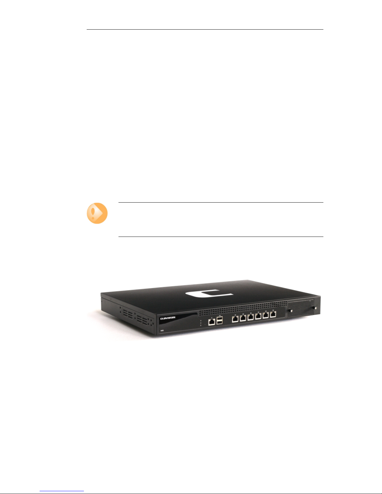
1.1. Unpacking the W30
Figure 1.1. An Unpacked Clavister W30 Appliance
This section details the unpacking of the W30 appliance. Open the packaging box used for
shipping and carefully unpack the contents. The delivered product packaging should contain the
following:
• The Clavister W30 appliance.
• RJ45 console cable.
• Power cable.
7

• A rack mount kit consisting of screws and 2 brackets suitable for a 19-inch rack.
Note: If any items are missing
If any items are missing from the W30 package, please contact the reseller or distributor.
All relevant documentation in PDF format can be downloaded from the Clavister
website and is included in the ZIP file distributions of new cOS Core versions.
Downloadable W30 Documentation
All documentation and other resources for the W30, including this guide, can be downloaded
from the W30 product page which can be found at http://www.clavister.com/start.
End of Life Treatment
The W30 appliance is marked with the European Waste Electrical and Electronic Equipment (WEEE)
directive symbol which is shown below.
The product, and any of its parts, should not be discarded of by means of regular refuse disposal.
At end-of-life, the product and parts should be given to an appropriate service that deals with
the removal of such specialist materials.
Chapter 1: W30 Product Overview
8
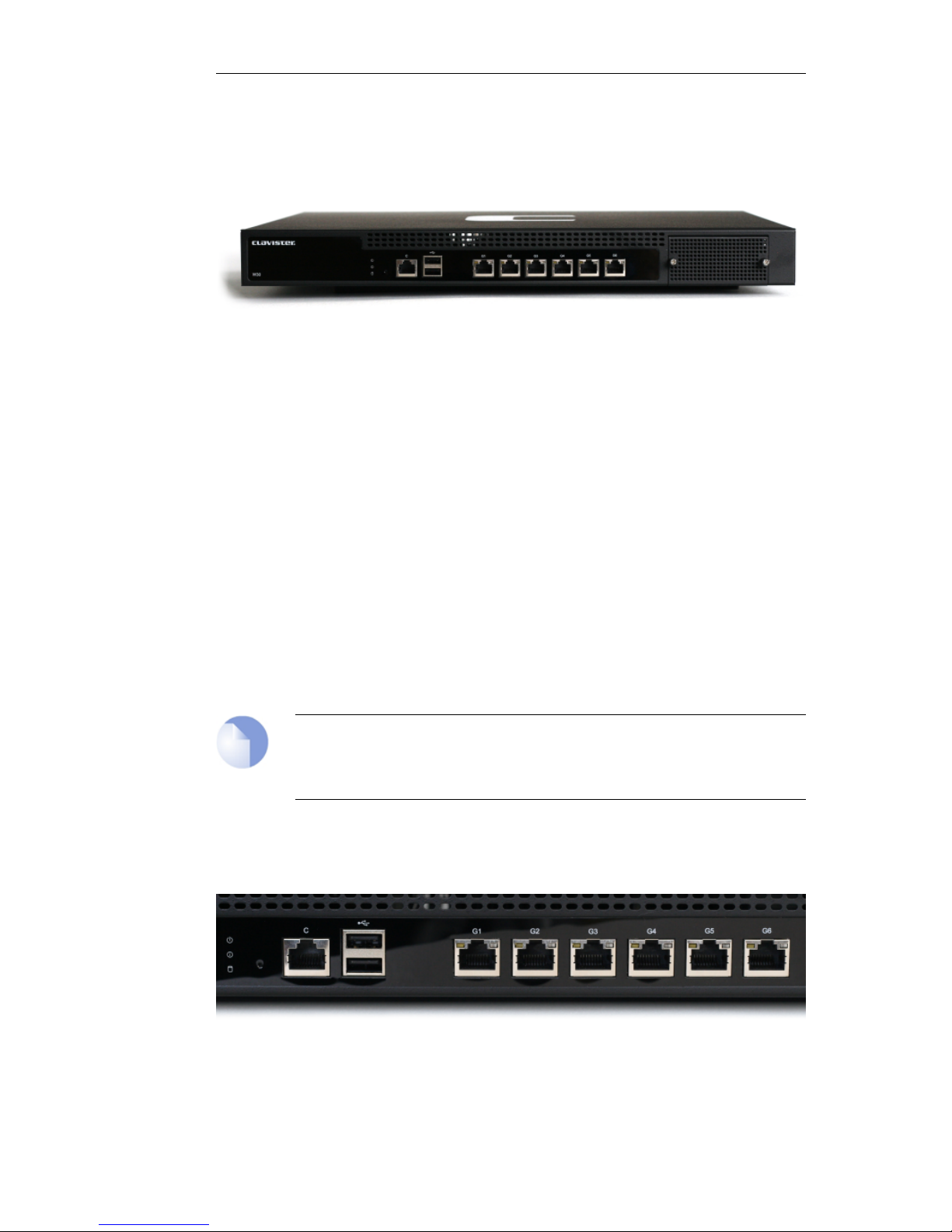
1.2. Interfaces and Ports
This section is an overview of the W30 product's external design.
Figure 1.2. Clavister W30 Connection Ports
The W30 features the following connection ports on the front panel:
• 6 x RJ45 Gigabit Ethernet interfaces with the logical cOS Core names G1, G2, G3, G4, G5, and
G6.
• An RS-232 RJ45 port for console connection marked with the letter C. This port is used for
direct access to the cOS Core Boot Menu and the cOS Core Command Line Interface (CLI).
• A single Ethernet interface expansion slot on the far right of the front panel. In a new unit,
this slot is covered with a removable grill as shown in the image above. An expansion module
can be ordered separately for this slot and the following module options are available:
i. 8 x RJ45 Gigabit Ethernet interfaces.
ii. 8 x SFP Gigabit interfaces.
iii. 2 x SFP+ 10 Gigabit interfaces.
Module installation is discussed in Chapter 5, Interface Expansion Modules.
Note: The two USB Type A ports are not currently used
The two USB Type A ports on the W30 front panel are for future functionality and are
not currently used by cOS Core.
All the Ethernet interface ports function independently of each other and are not connected by a
switch fabric. All are capable of link speed auto-negotiation and can operate using 10Base-T,
100Base-Tx, or 1000Base-T. The interfaces names are written by each interface.
Figure 1.3. The W30 Ethernet Interface Ports
The full connection capabilities of all W30 Ethernet interfaces are listed in Appendix A, W30
Chapter 1: W30 Product Overview
9

Specifications.
Chapter 1: W30 Product Overview
10

Chapter 1: W30 Product Overview
11

Chapter 2: Registering with Clavister
Before applying power to the W30 and starting cOS Core, it is important to understand the the
customer and product registration procedures. There are two types of registration:
• Registering as a Clavister Customer
This involves registering basic contact and company information on the Clavister website
and establishing login credentials. Later, these credentials can also be used by cOS Core for
automatically registering the W30 hardware unit and automatically downloading the correct
license.
This is is a mandatory requirement for all new customers and needs to be done only once. A
description of doing this can be found below. Even if registration is not done before starting
the cOS Core wizard, the wizard will provide a link to the registration page so it can be done
while the wizard is running.
• Registration of the W30 Hardware Unit
This is mandatory for every hardware unit before a license can be downloaded. It can be
done in the following ways:
i. Automatic registration after cOS Core starts - This can done by the Setup Wizard
which starts automatically in a browser popup window when cOS Core Web Interface is
started for the first time. The wizard is described in Section 4.2, “Web Interface and Wizard
Setup”.
ii. Manual registration of the W30 on the Clavister website - This is described in the last
half of this section. Manual registration may be necessary if the W30 does not have
Internet access.
A. Registering as a Clavister Customer
The W30 registration steps for a first time user of Clavister hardware are as follows:
1. Open a web browser, surf to http://www.clavister.com and select Log in.
12
2. The customer login page is presented. It is assumed that a new customer is accessing the
site for the first time so they should press the Register button. If already registered, log in
and skip to step 8.
3. The registration webpage is now presented. The required information should be filled in. In
the example below, a user called John Smith registers. It is important to enter the
administrator's company details as well. Without company details, a license cannot be
created.
4. When the registration details are accepted, an email is sent to the email address given so
that the registration can be confirmed.
Chapter 2: Registering with Clavister
13
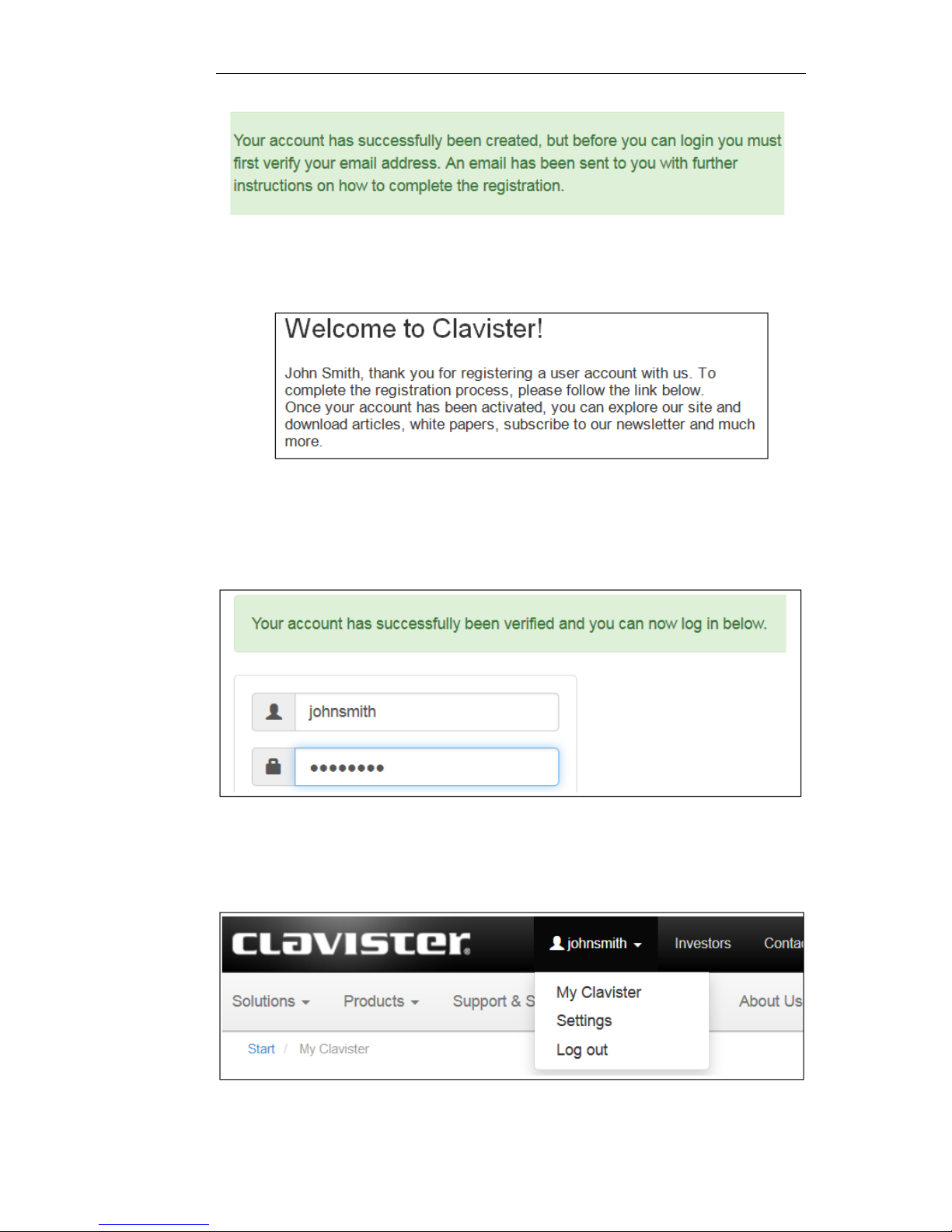
5. Below is an example of the email that John Smith would receive.
6. When the confirmation link in the email is clicked, the new customer is taken to a webpage
to indicate that confirmation has been successful. They should now log in to the Clavister
website with the credentials they have submitted during registration.
7. After logging in, the website toolbar will show the name of the currently logged in
customer.
Chapter 2: Registering with Clavister
14
B. Registration of the W30 Hardware Unit
These steps describe manual registration of the W30 hardware unit.
Alternatively, if the W30 is connected to the Internet then this registration can be also be
performed automatically by the cOS Core Setup Wizard which will appear as a browser popup
window in the Web Interface when cOS Core starts for the first time.
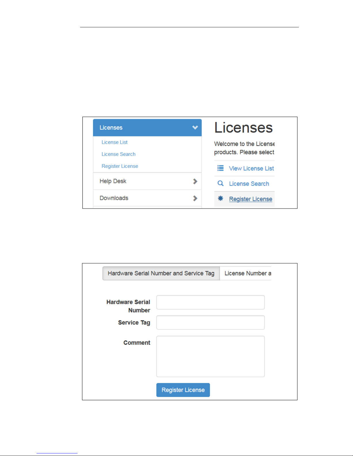
1. Log in to the Clavister website and select the Register License option.
2. The registration page is displayed. Under the tab Hardware Serial Number and Service
Tag, enter the Hardware Serial Number and Service Tag must be entered. These two codes
are found on a label which should be attached to the W30 hardware itself. The label is
usually found on the hardware's underside but may by found in another position.
Chapter 2: Registering with Clavister
15

The image above shows an example label which illustrates the typical layout of identification
labels found on Clavister hardware products.
After Successful Hardware Registration
Once the W30 hardware unit is registered, a cOS Core license for the unit becomes available for
download and installation from Clavister servers. This installation can be done automatically
through the cOS Core Setup Wizard which is described in Section 4.2, “Web Interface and Wizard
Setup”.
If the W30 is not connected to the Internet, the license must be manually downloaded from the
cOS Core website and then manually uploaded.
All license installation options are listed and discussed in Section 4.5, “License Installation
Methods”.
Chapter 2: Registering with Clavister
16

Chapter 3: W30 Installation
• General Installation Guidelines, page 17
• Flat Surface Installation, page 19
• Rack Installation, page 20
• Local Console Port Connection, page 21
• Connecting Power, page 23
3.1. General Installation Guidelines
Follow these geneneral guidelines when installing your Clavister W30 appliance:
• Safety
Take notice of the safety guidelines laid out in Chapter 8, Safety Precautions. These are
specified in multiple languages.
• Power
Make sure that the power source circuits are properly grounded and then use the power cord
supplied with the appliance to connect it to the power source.
• Using Other Power Cords
If your installation requires a different power cord than the one supplied with the appliance,
be sure to use a cord displaying the mark of the safety agency that defines the regulations for
power cords in your country. Such marks are an assurance that the cord is safe.
• Power Overload
Ensure that the appliance does not overload the power circuits, wiring and over-current
protection.
To determine the possibility of overloading the supply circuits, add together the ampere
ratings of all devices installed on the same circuit as the appliance and compare the total
with the rating limit for the circuit. The maximum ratings for the W30 are listed in Appendix A,
W30 Specifications.
• Surge Protection
17

A third party surge protection device should be considered and is strongly recommended as
a means to prevent electrical surges reaching the appliance. This is mentioned again in
Section 3.5, “Connecting Power”.
• Temperature
Do not install the appliance in an environment where the ambient temperature during
operation might fall outside the specified operating range. This range is documented in
Appendix A, W30 Specifications.
The intended operating temperature range is "room temperature". That is to say, the
temperature most commonly found in a modern office and in which humans feel
comfortable. This is usually considered to be between 20 and 25 degrees Celsius (68 to 77
degrees Fahrenheit). Special rooms for computer equipment may use a lower range and this
is also acceptable.
• Airflow
Make sure that airflow around the appliance is not restricted.
• Dust
Do not expose the appliance to environments with elevated dust levels.
Note: The specifications appendix provides more details
Detailed information concerning power supply range, operating temperature range and
other operating details can be found at the end of this publication in Appendix A, W30
Specifications.
Chapter 3: W30 Installation
18

3.2. Flat Surface Installation
The W30 can be mounted on any appropriate stable, flat, level surface that can safely support the
weight of the appliance and its attached cables. However, the W30 is designed to be rack
mounted and installation on a flat surface is not recommended.
Caution: Always leave space around the appliance
Always ensure there is adequate space around the appliance for ventilation and access
to operating switches and cable connectors. No objects should be placed on top of the
casing.
Chapter 3: W30 Installation
19
3.3. Rack Installation
The W30 is designed to be installed in most standard 19-inch equipment racks.
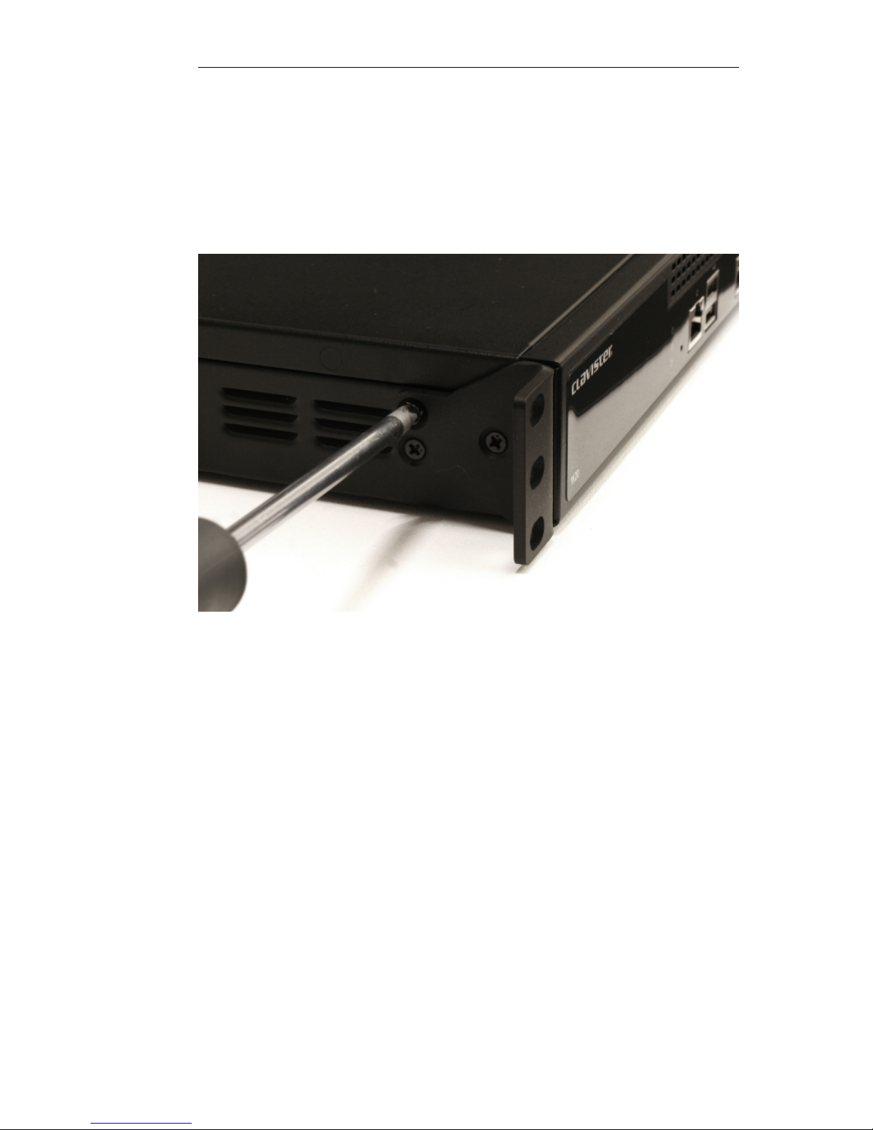
In the packaging for the W30 there should be included a Rack Mount Kit which consists of two
brackets, each of which has three screws for attachment to the front-sides of the unit as shown in
the image below. There are predrilled holes already in the sides of the W30 unit which must be
used for attaching the brackets.
After attaching a bracket to either side of the unit, it is ready for rack mounting using a suitable
fastener. Rear support is not necessary.
Rack Mounting Guidelines
The following mounting guidelines should be followed:
• A rack or cabinet used for mounting should be adequately secured to prevent it from
becoming unstable and/or falling over.
• Devices installed in a rack or cabinet should be mounted as low as possible, with the heaviest
devices at the bottom and progressively lighter devices installed above.
Chapter 3: W30 Installation
20
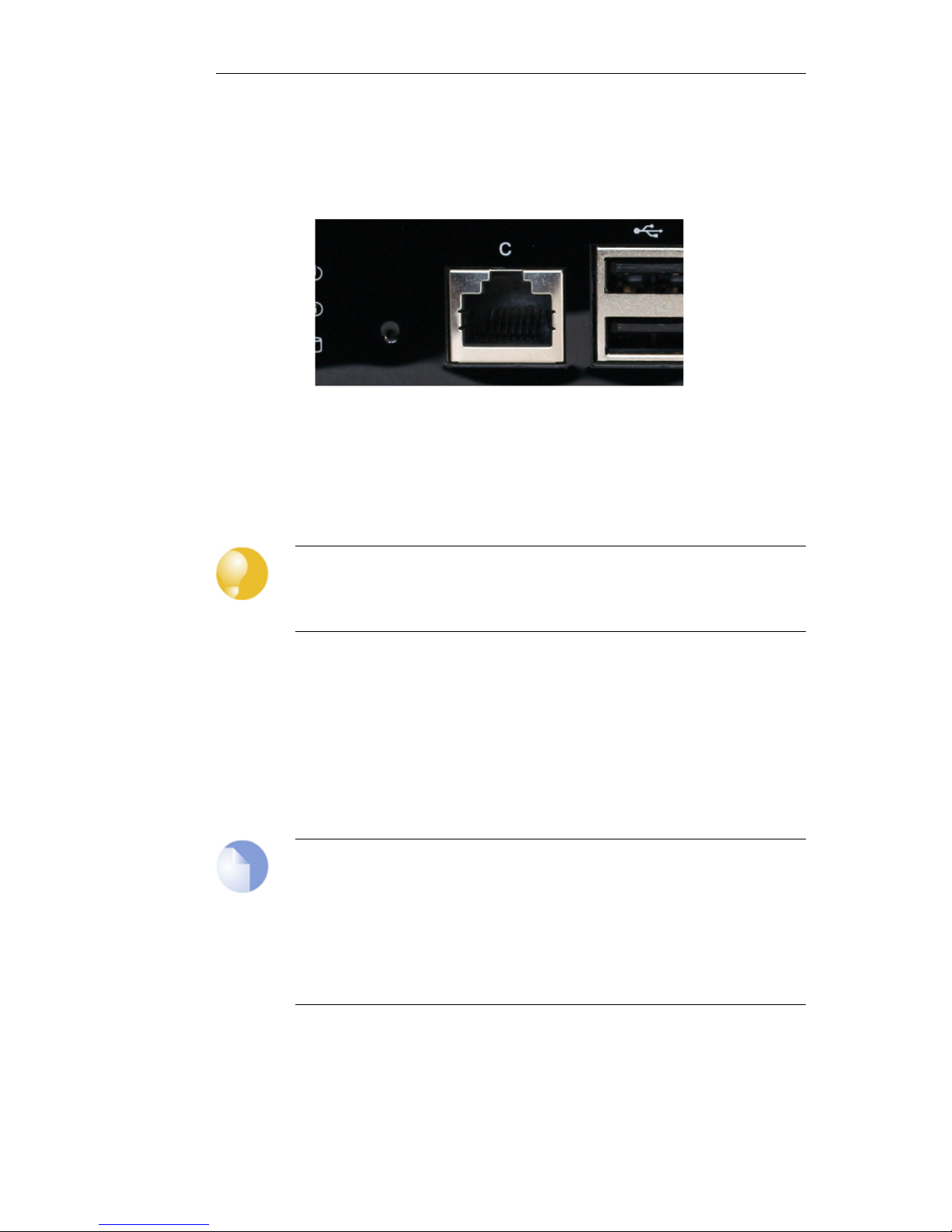
3.4. Local Console Port Connection
The local console port is the physical RJ45 RS-232 port on the far left-hand side front panel of the
W30 and is marked with the letter "C".
Figure 3.1. The W30 Local Console Port
This local console port allows direct management connection to the appliance, either from a
separate computer running console emulation software or from a console terminal. Local
console access can then be used for both management of cOS Core with CLI commands or to
enter the boot menu in order to access W30 firmware loader options.
Tip: Skip the rest of this section if using the Web Interface
This rest of this section can be initially skipped if cOS Core setup is going to be done with
the cOS Core Web Interface since neither boot menu or CLI access will be needed.
Issuing CLI Commands
CLI commands can be issued via the local console port for both initial cOS Core setup as well as
for ongoing system administration.
The local console port need not be used if setup is done through a web browser as described in
Section 4.2, “Web Interface and Wizard Setup”. If the local console port is used for setup, no
password is initially needed and the CLI commands required are described in Section 4.4, “CLI
Setup”.
Note: Setting a local console password is recommended
A local console password need not be set. However, if it is not, anyone with physical
access to the local console will have full administrator rights.
Unless the hardware is placed in a secure area, it is therefore recommended to set a local
console password. This is done by entering the console boot menu at system startup by
pressing any console key before cOS Core has fully started. The boot menu and its
options is discussed further in the separate cOS Core Administrators Guide.
Requirements for Local Console Connection
To get management access via the local console port, the following is needed:
Chapter 3: W30 Installation
21

• A terminal or a computer with a serial port and the ability to emulate a terminal (for example,
the open source puTTY software).
• The terminal console should have the following settings:
i. 9600 bps.
ii. No parity.
iii. 8 bits.
iv. 1 stop bit.
v. No flow control.
• An RS-232 cable with appropriate terminating connectors.
Connection Steps
To connect a terminal to the local console port, perform the following steps:
1. Check that the console connection settings are configured as described above.
2. Connect one of the connectors on the cable directly to the local console port on the W30.
3. Connect the other end of the cable to a console terminal or to the serial connector of a
computer running console emulation software.
Connection Using SSH
An alternative to using the local console port for CLI access is to connect via a physical Ethernet
interface and using a Secure Shell (SSH) client on the management workstation to issue CLI
commands. This is discussed further in Section 4.1, “Management Workstation Connection”.
Chapter 3: W30 Installation
22
3.5. Connecting Power
This section describes connecting power. As soon as power is applied, the W30 will boot-up and
cOS Core will start.
Important
Please review the electrical safety information in Chapter 8, Safety Precautions.
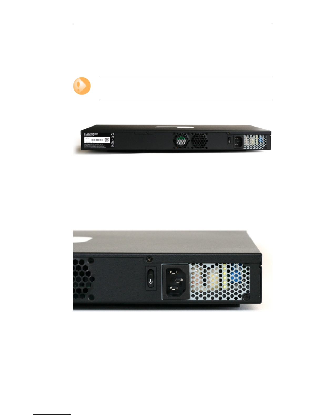
The image below shows the back of the W30. This is divided into four sections secured by screws.
Figure 3.2. Rear view of the Clavister W30
Connecting AC Power
To connect power, follow these steps:
1. Plug the end of the power cord into the power inlet socket on the W30.
Figure 3.3. W30 Power Switch and Power Inlet Socket
2. Plug the other end of the power cord into a grounded power outlet.
3. Power is controlled by a rocker switch situated to the left of the power inlet socket. To
switch on, depress the upper part of the switch to move it to the On position.
Chapter 3: W30 Installation
23

4. The W30 will boot up and cOS Core will start. After a brief period of time, cOS Core will be
initialized and the W30 appliance is ready for configuration from a management
workstation using either the Web Interface or the Command Line Interface (CLI) as the
management interface.
Initial configuration is discussed in detail in Chapter 4, cOS Core Configuration.
Important: Protecting Against Power Surges
It is recommended that the purchase and use of a separate surge protection unit from a
third party is considered for the power connection to the W30 hardware. This is to ensure
that the W30 is protected from damage by sudden external electrical power surges
through the power cable.
Surge protection is particularly important in locations where there is a heightened risk of
lightning strikes and/or power grid spikes.
Any surge protection unit should be installed exactly according to the manufacturer's
instructions since correct installation of such units is vital for them to be effective.
Chapter 3: W30 Installation
24

Chapter 3: W30 Installation
25

Chapter 4: cOS Core Configuration
• Management Workstation Connection, page 26
• Web Interface and Wizard Setup, page 29
• Manual Web Interface Setup, page 37
• CLI Setup, page 53
• License Installation Methods, page 61
• Setup Troubleshooting , page 63
• Going Further with cOS Core, page 65
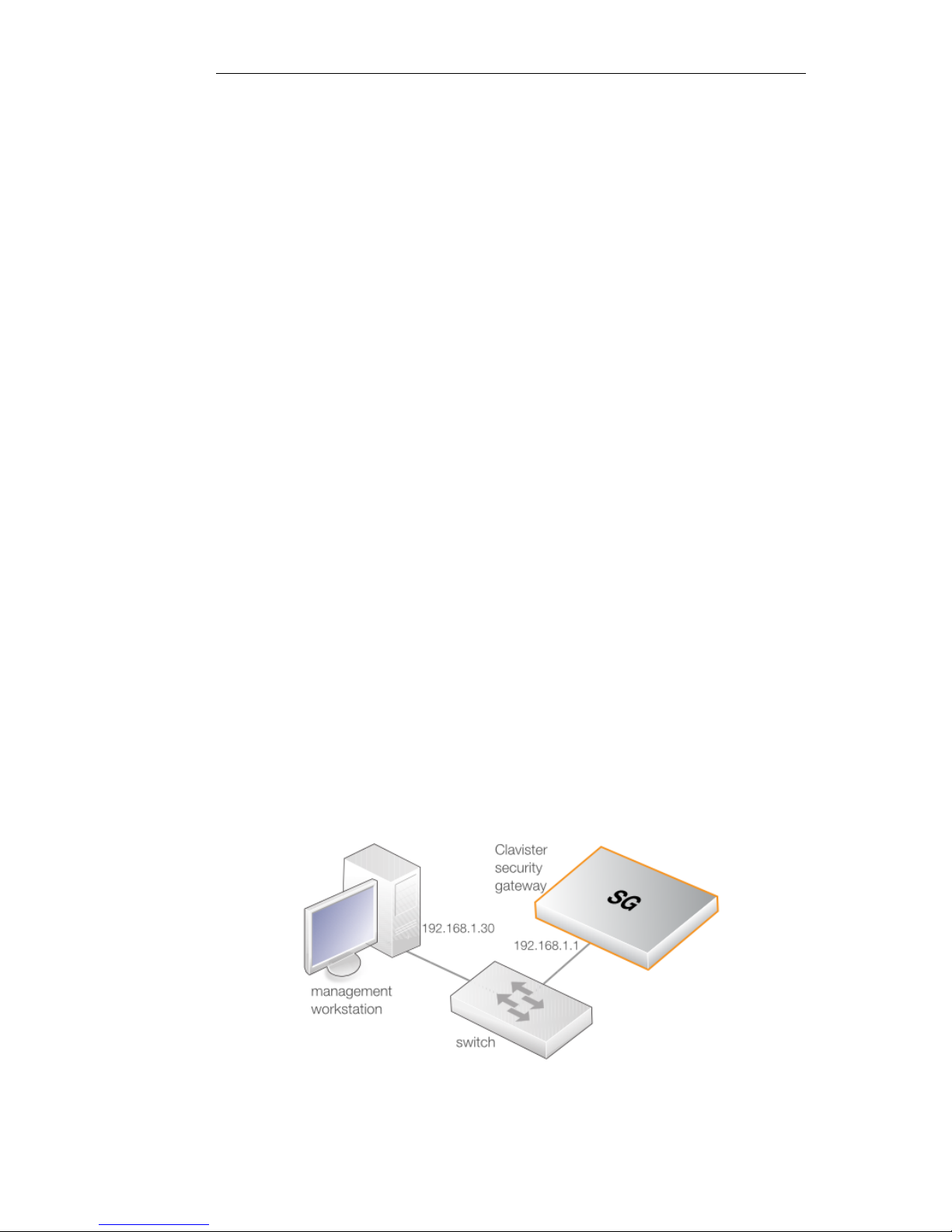
4.1. Management Workstation Connection
cOS Core Starts After Power Up
It is assumed that the W30 unit is now unpacked, positioned correctly and powered is applied. If
not, the earlier chapters in this manual should be referred to before continuing.
Clavister's cOS Core network security operating system is preloaded on the W30 and will
automatically boot up after power is applied. After boot-up is complete, an external
management computer workstation can be used to configure cOS Core.
The Default Management Interface
After first time startup, cOS Core automatically makes management access available on a single
predefined Ethernet interface and assigns the private IPv4 address 192.168.1.1 to it.
For the W30, the default management interface is the G1 interface.
cOS Core Setup Methods
Initial cOS Core software configuration can be done in one of the following ways:
• Through a web browser.
26
A standard web browser running on a standalone computer (also referred to as the
management workstation) can be used to access the cOS Core Web Interface. This provides an
intuitive graphical interface for cOS Core management. When this interface is accessed for
the first time, a setup wizard runs automatically to guide a new user through key setup steps.
The wizard can be closed if the administrator wishes to go directly to the Web Interface to
perform setup manually.
The wizard is recommended for its simplification of initial setup and is described in detail in
Section 4.2, “Web Interface and Wizard Setup”. The wizard assumes that connection to the
public Internet is one of the tasks to be performed and has a step for this.
• Through a terminal console using CLI commands.
Alternatively, the setup process can be performed using console CLI commands and this is
described in Section 4.4, “CLI Setup”. The CLI allows step by step control of setup and should
be used by administrators who fully understand both the CLI and setup process.
CLI access is possible in one of two ways:
i. CLI access can be remote, across a network to a physical Ethernet interface. This is a
similar to the connection used with the Web Interface and is also done using the default
management interface after powering up for the first time.
ii. Alternatively, CLI access can be through console emulation software running on a
separate management computer connected directly to the RJ45 local console port on
the W30 hardware. Direct console connection is described in Section 3.4, “Local Console
Port Connection”.
Network Connection Setup
For setup using the Web Interface via a web browser or the CLI via SSH, it is necessary to connect
an Ethernet interface on an external workstation computer to the default management Ethernet
interface on the W30.
The default management Ethernet interface for the W30 is G1 and this is assigned the default
IPv4 address of 192.168.1.1 by cOS Core. This interface should be connected to the same
network as the management workstation (or a network accessible from the workstation via one
or more switches).
Typically, the connection between the management workstation and the default management
interface is made via a switch using standard Ethernet cables, as shown in the illustration below.
For connection to the public Internet, another W30 Ethernet interface should be connected to an
ISP and this is referred to in the setup wizard as the WAN interface. In this guide, it is assumed
Chapter 4: cOS Core Configuration
27

that the physical G2 interface of the W30 is used for Internet connection, although any other
unused interface could be used instead.
Direct Connection to the Management Interface
Connection to the management interface G1 from the workstation can be done directly without
a switch. This could be done using a crossover cable. However, all the RJ45 interfaces on the W30
support Automatic MDI-X and a crossover cable is not necessary.
Workstation Ethernet Interface Setup
Traffic will be able to flow between the designated workstation interface and the Clavister
Security Gateway interface because they are on the same IP network. This means the workstation
interface should be first assigned the following static IPv4 addresses:
• IP address: 192.168.1.30
• Subnet mask: 255.255.255.0
• Default gateway: 192.168.1.1
Tip: Using another workstation interface IP address
The IPv4 address assigned to the management workstation's Ethernet interface, could
be any address from the 192.168.1.0/24 network. However, the IP chosen must be
different from 192.168.1.1 which is used by cOS Core's default management interface.
The following appendices at the end of this guide describe how to set up the management
workstation IP with different operating systems:
• Appendix C, Windows XP IP Setup.
• Appendix D, Windows Vista IP Setup.
• Appendix E, Windows 7 IP Setup.
• Appendix F, Windows 8 IP Setup.
• Appendix G, Apple Mac IP Setup.
Chapter 4: cOS Core Configuration
28
4.2. Web Interface and Wizard Setup
This chapter describes the setup when accessing cOS Core for the first time through a web
browser. The user interface accessed in this way is called the Web Interface. It assumes that a
physical network connection has been set up from a management computer to the default
management Ethernet interface as described in Section 4.1, “Management Workstation
Connection”.
Note: Some screenshot images have been clipped
Many of the images in this section are cut from original screenshots to condense the
information presented. However, all relevant details in the images have been preserved.
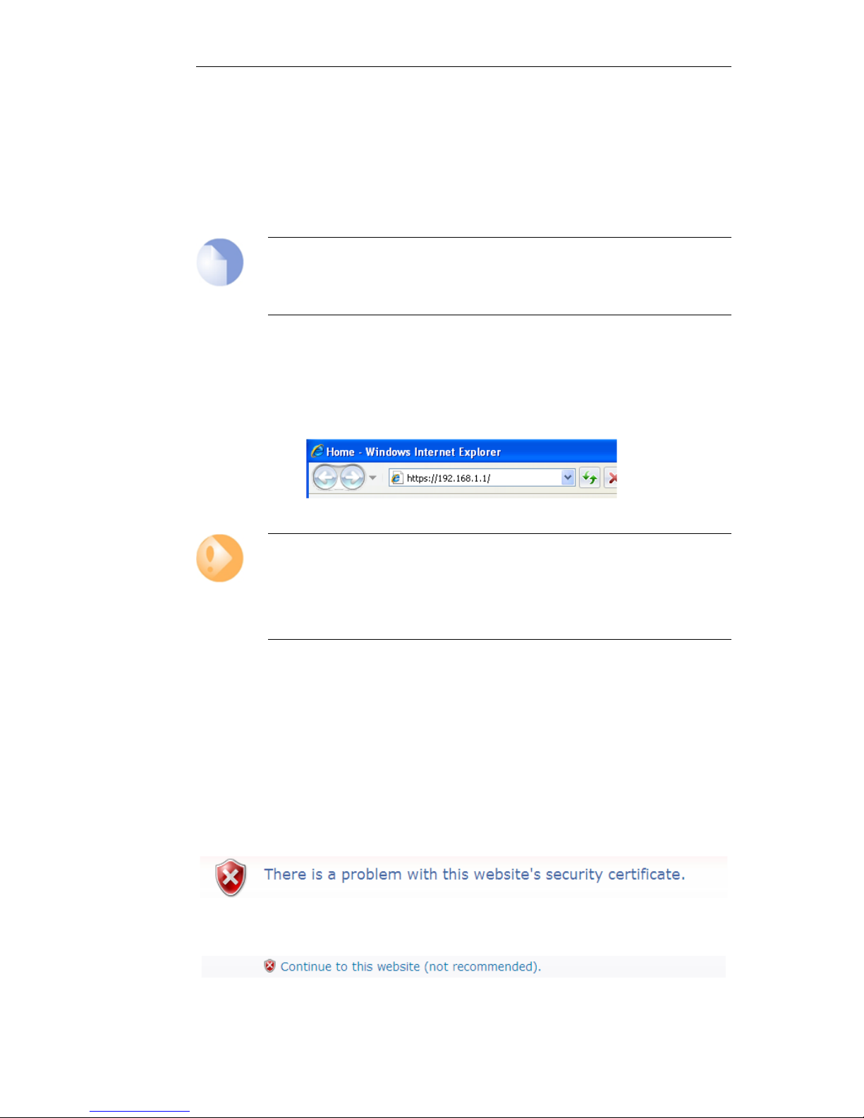
Connect By Browsing to https://192.168.1.1
Using a web browser, enter the address https://192.168.1.1 into the navigation window as shown
below.
Important: Disable any proxy server and turn off popup blocking
Make sure the web browser doesn't have a proxy server configured.
The wizard runs in a browser popup window. The popup must be allowed for the setup
wizard to run.
If there is no response from cOS Core and the reason is not clear, refer to the help checklist in
Section 4.6, “Setup Troubleshooting ”.
The cOS Core Self-signed Certificate
When responding to an https:// request, by default cOS Core sends a self-signed certificate which
will not be initially recognized so it will be necessary to tell the browser to accept the certificate
for this and future sessions.
Different browsers handle this self-signed certificate in slightly different ways. In Microsoft
Internet Explorer the following error message will be displayed in the browser window.
To continue, tell IE to accept the certificate by clicking the following link which appears near the
bottom of the browser window.
In Firefox, this procedure is called "Add a security exception".
Chapter 4: cOS Core Configuration
29
 Loading...