

Clavister Eagle E5, Lynx X8, Eagle E7 Getting Started Manual

Clavister Eagle E5
Getting Started Guide
Clavister AB
Sjögatan 6J
SE-89160 Örnsköldsvik
SWEDEN
Phone: +46-660-299200
www.clavister.com
Published 2014-12-12
Copyright © 2014 Clavister AB

Clavister Eagle E5
Getting Started Guide
Published 2014-12-12
Copyright © 2014 Clavister AB
Copyright Notice
This publication, including all photographs, illustrations and software, is protected under
international copyright laws, with all rights reserved. Neither this manual, nor any of the material
contained herein, may be reproduced without the written consent of Clavister.
Disclaimer
The information in this document is subject to change without notice. Clavister makes no
representations or warranties with respect to the contents hereof and specifically disclaims any
implied warranties of merchantability or fitness for a particular purpose. Clavister reserves the
right to revise this publication and to make changes from time to time in the content hereof
without any obligation to notify any person or parties of such revision or changes.
Limitations of Liability
UNDER NO CIRCUMSTANCES SHALL CLAVISTER OR ITS SUPPLIERS BE LIABLE FOR DAMAGES OF
ANY CHARACTER (E.G. DAMAGES FOR LOSS OF PROFIT, SOFTWARE RESTORATION, WORK
STOPPAGE, LOSS OF SAVED DATA OR ANY OTHER COMMERCIAL DAMAGES OR LOSSES)
RESULTING FROM THE APPLICATION OR IMPROPER USE OF THE CLAVISTER PRODUCT OR
FAILURE OF THE PRODUCT, EVEN IF CLAVISTER IS INFORMED OF THE POSSIBILITY OF SUCH
DAMAGES. FURTHERMORE, CLAVISTER WILL NOT BE LIABLE FOR THIRD-PARTY CLAIMS AGAINST
CUSTOMER FOR LOSSES OR DAMAGES. CLAVISTER WILL IN NO EVENT BE LIABLE FOR ANY
DAMAGES IN EXCESS OF THE AMOUNT CLAVISTER RECEIVED FROM THE END-USER FOR THE
PRODUCT.
2

Table of Contents
Preface ........ ................ ................. ................ ................. ................ ................ ...... 5
1. Product Overview . .............. ................. ................ ................ ................. ............. 7
1.1. Unpacking the Product . .............. ................ ................. ................ ............ 7
1.2. Interfaces and Ports ... ................ ................. ................ ................ ............. 9
2. Installation ................ ................. ................ ................. ................ ................ .... 12
2.1. Installation Guidelines ........... ................ ................. ................ ................12
2.2. Rack Mounting ........ ................ ................. ................ ................. ............ 14
2.3. Local Console Port Connection .......... ................ ................. ................ ...... 16
2.4. Connecting Power ............ ................ ................. ................ ................. .... 18
2.5. Resetting to Factory Defaults .......... ................ ................ ................. ........ 19
3. cOS Core Configuration . ................ ................ ................. ................ ................ ... 21
3.1. Management Workstation Connection ........... ................ ................ ........... 21
3.2. Web Interface and Wizard Setup ............ ................. ................ ................ .. 24
3.3. Manual Web Interface Setup ......... ................ ................. ................ .......... 32
3.4. CLI Setup ......... ................ ................. ................ ................ ................. ... 48
3.5. Installing a License ........... ................. ................ ................ ................. .... 56
3.6. Setup Troubleshooting ............... ................. ................ ................. .......... 58
3.7. Going Further with cOS Core ......... ................. ................ ................. ......... 60
4. Warranty Service ....... ................. ................ ................. ................ ................ ..... 63
5. Safety Precautions ..... ................. ................ ................. ................ ................ ..... 65
A. E5 Specifications ..... ................. ................ ................ ................. ................ ....... 68
B. Declarations of Conformity ................ ................ ................. ................ ............... 69
C. Port Based VLAN Setup . ............. ................. ................ ................ ................. ..... 71
3

List of Figures
1.1. An Unpacked Clavister E5 Appliance ........... ................ ................. ................ ...... 7
1.2. Clavister E5 Connection Ports . ................ ................ ................ ................. .......... 9
1.3. The E5 Ethernet Interface Ports ........ ................ ................. ................ ................ . 9
2.1. The E5 Local Console Port . ............... ................. ................ ................ ............... 16
2.2. E5 Power Inlet Socket ............... ................. ................ ................ ................. .... 18
4

Preface
Target Audience
The target audience for this guide is the administrator who has taken delivery of a packaged
Clavister E5 appliance and is setting it up for the first time. The guide takes the user from
unpacking and installation of the device through to power-up, including network connections
and initial cOS Core configuration.
Text Structure
The text is divided into chapters and subsections. Numbered subsections are shown in the table
of contents at the beginning of the document.
Notes to the main text
Special sections of text which the reader should pay special attention to are indicated by icons
on the left hand side of the page followed by a short paragraph in italicized text. There are the
following types of such sections:
Note
This indicates some piece of information that is an addition to the preceding text. It may
concern something that is being emphasized or something that is not obvious or
explicitly stated in the preceding text.
Tip
This indicates a piece of non-critical information that is useful to know in certain
situations but is not essential reading.
Caution
This indicates where the reader should be careful with their actions as an undesirable
situation may result if care is not exercised.
Important
This is an essential point that the reader should read and understand.
Warning
This is essential reading for the user as they should be aware that a serious situation
may result if certain actions are taken or not taken.
5

Text links
Where a "See section" link is provided in the main text, this can be clicked on to take the reader
directly to that reference. For example, see Section 3.6, “Setup Troubleshooting ”.
Web links
Web links included in the document are clickable. For example, http://www.clavister.com.
Trademarks
Certain names in this publication are the trademarks of their respective owners.
cOS Core is the trademark of Clavister AB.
Windows, Windows XP, Windows Vista and Windows 7 are either registered trademarks or
trademarks of Microsoft Corporation in the United States and/or other countries.
Apple, Mac and Mac OS are trademarks of Apple Inc. registered in the United States and/or other
countries.
Preface
6
Chapter 1: Product Overview
• Unpacking the Product, page 7
• Interfaces and Ports, page 9
1.1. Unpacking the Product
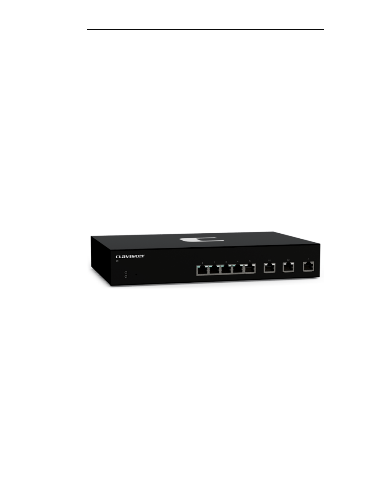
Figure 1.1. An Unpacked Clavister E5 Appliance
This section details the unpacking of the E5 appliance. Open the packaging box used for
shipping and carefully unpack the contents. The delivered product packaging should contain the
following:
• The Clavister E5 appliance.
• RJ45 Ethernet cable.
• Power cable.
• A rack mount kit consisting of brackets and screws suitable for a 19-inch rack.
The E5 has an internal 100-240V AC, 50-60Hz, 0.4A power adaptor.
7

Note: If any items are missing
If any items are missing from your package, please contact your reseller or distributor.
All relevant documentation can be downloaded in PDF format from the Clavister
website.
Downloadable E5 Documentation
All documentation and other resources for the E5, including this guide, can be downloaded from
the E5 product page which can be found at http://www.clavister.com/start.
End of Life Treatment
The E5 appliance is marked with the European Waste Electrical and Electronic Equipment (WEEE)
directive symbol which is shown below.
The product, and any of its parts, should not be discarded of by means of regular refuse disposal.
At end-of-life, the product and parts should be given to an appropriate service that deals with
the removal of such specialist materials.
Chapter 1: Product Overview
8
1.2. Interfaces and Ports
This section is an overview of the E5 product's external design.
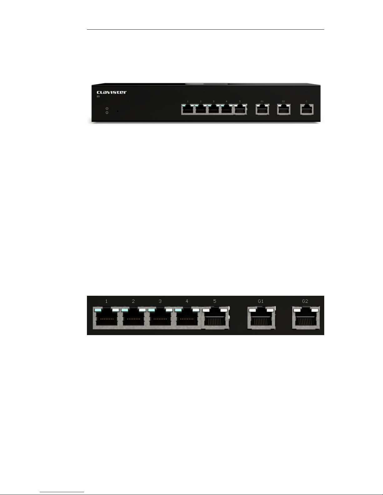
Figure 1.2. Clavister E5 Connection Ports
The E5 features the following connection ports on the front panel:
• On the left there is a set of RJ45 Gigabit Ethernet interfaces which are numbered 1 to 5. All 5
interfaces are connected together by a common switch fabric and share the single logical
cOS Core interface name GESW. This means that any security policy in the cOS Core rule sets
that refers to the interface GESW can apply to traffic on any of the 5 physical interfaces.
The GESW interfaces allow the configuration of Port Based VLANs through cOS Core so that
the 5 interfaces can be divided up into different VLANs. This feature is described further in
Appendix C, Port Based VLAN Setup.
• Next, are 2 x RJ45 Gigabit Ethernet interfaces. These have the logical cOS Core names of G1
and G2. The names are marked on each interface. These interfaces function independently of
each other and are not connected by a switch fabric and can be used for any purpose.
• Last, is an RJ45 console port which is used for direct access to the cOS Core Boot Menu and
the cOS Core Command Line Interface (CLI). Access can be password protected.
All E5 Ethernet interfaces are capable of link speed auto-negotiation and can operate using
10Base-T, 100Base-Tx, or 1000Base-T.
Figure 1.3. The E5 Ethernet Interface Ports
All the E5 Ethernet interfaces support Automatic MDI-X and do not require a crossover cable for
direct connection from another computer.
The full connection capabilities of all E5 Ethernet interfaces are listed in Appendix A, E5
Specifications.
Ethernet Interface Status LEDs
On the E5 there are indicator lights at the top left and top right of each interface which illuminate
according to link status and activity. The conditions shown are:
Chapter 1: Product Overview
9

• The top-left flashes green to indicate data traffic.
• The top-right light is green if the link is 10 or 100 Mb.
• The top-right light is amber if the link is 1 Gb.
Note: The GESW interface cannot be used with link aggregation
If the cOS Core link aggregation feature is used, the logical GESW interface cannot be
part of a LinkAggregation object.
Chapter 1: Product Overview
10

Chapter 1: Product Overview
11

Chapter 2: Installation
• Installation Guidelines, page 12
• Rack Mounting, page 14
• Local Console Port Connection, page 16
• Connecting Power, page 18
• Resetting to Factory Defaults, page 19
2.1. Installation Guidelines
Guidelines
Follow these guidelines when installing your Clavister E5 appliance:
• Safety
Take notice of the safety guidelines laid out in Chapter 5, Safety Precautions. These are
specified in multiple languages.
• Power
Make sure that the power source circuits are properly grounded and then use the power cord
supplied with the appliance to connect it to the power source.
• Using Other Power Cords
If your installation requires a different power cord than the one supplied with the appliance,
be sure to use a cord displaying the mark of the safety agency that defines the regulations for
power cords in your country. Such marks are an assurance that the cord is safe.
• Power Overload
Ensure that the appliance does not overload the power circuits, wiring and over-current
protection.
To determine the possibility of overloading the supply circuits, add together the ampere
ratings of all devices installed on the same circuit as the appliance and compare the total
with the rating limit for the circuit. The maximum ratings for the E5 are listed in Appendix A, E5
12

Specifications.
• Surge Protection
A third party surge protection device should be considered and is strongly recommended as
a means to prevent electrical surges reaching the appliance. This is mentioned again in
Section 2.4, “Connecting Power”.
• Temperature
Do not install the appliance in an environment where the ambient temperature during
operation might fall outside the specified operating range. This range is documented in
Appendix A, E5 Specifications.
The intended operating temperature range is "room temperature". That is to say, the
temperature most commonly found in a modern office and in which humans feel
comfortable. This is usually considered to be between 20 and 25 degrees Celsius (68 to 77
degrees Fahrenheit). Special rooms for computer equipment may use a lower range and this
is also acceptable.
• Airflow
Make sure that airflow around the appliance is not restricted.
• Dust
Do not expose the appliance to environments with elevated dust levels.
Note: The specifications appendix provide details
Detailed information concerning power supply range, operating temperature range and
other operating details can be found at the end of this publication in Appendix A, E5
Specifications.
Flat Surface Installation
The E5 can be mounted on any appropriate stable, flat, level surface that can safely support the
weight of the appliance and its attached cables.
Caution: Always leave space around the appliance
Always ensure there is adequate space around the appliance for ventilation and access
to operating switches and cable connectors. No objects should be placed on top of the
casing.
The E5 can also be rack mounted in a 19-inch rack using the kit which is included with the
product and this is described next in Section 2.2, “Rack Mounting”.
Chapter 2: Installation
13
2.2. Rack Mounting
A Rack Mount Kit is supplied with the E5 for mounting the product in a 19-inch rack. Included
with the kit is the following:
• 2 x side brackets.
• 8 x bracket screws, 4 for securing one bracket to the either side of the E5.
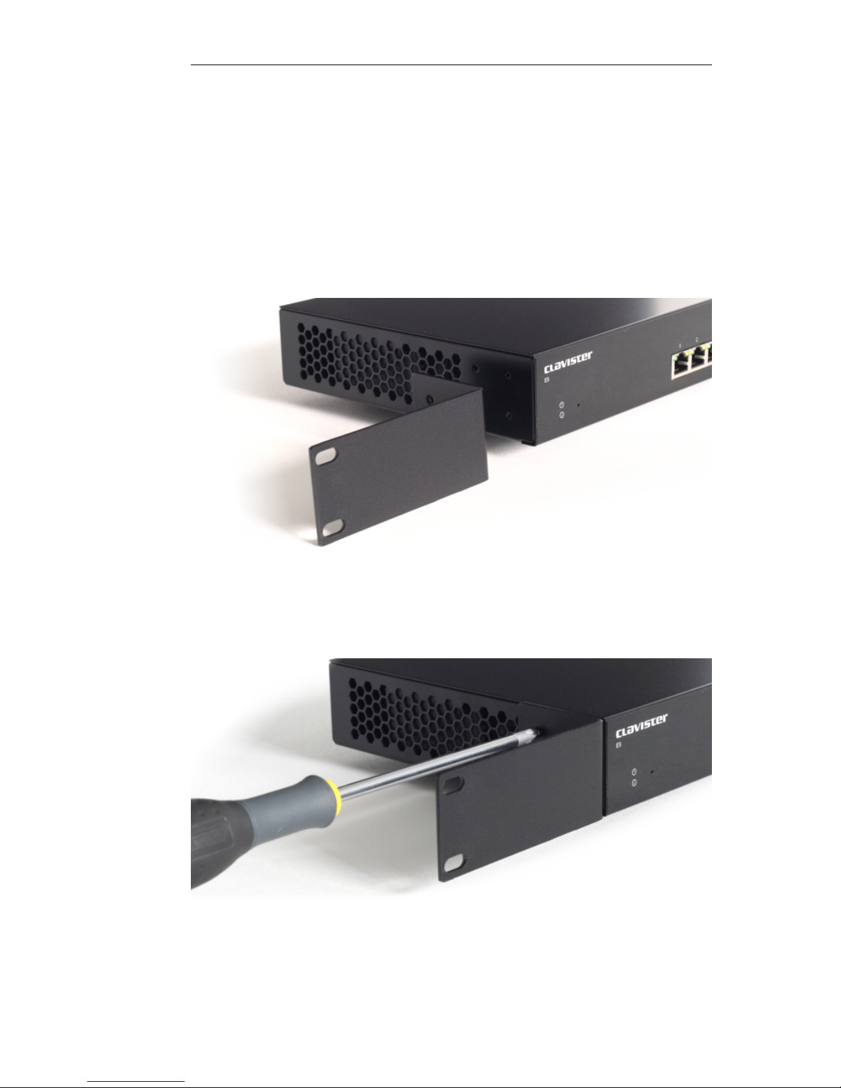
The kit is attached to the sides of the E5 unit prior to mounting in the rack. There are predrilled
holes in each bracket as shown below.
Align the brackets screw holes with the predrilled holes on the side of the E5, then fit and tighten
the supplied screws into the holes with a suitable screwdriver as shown below.
Chapter 2: Installation
14
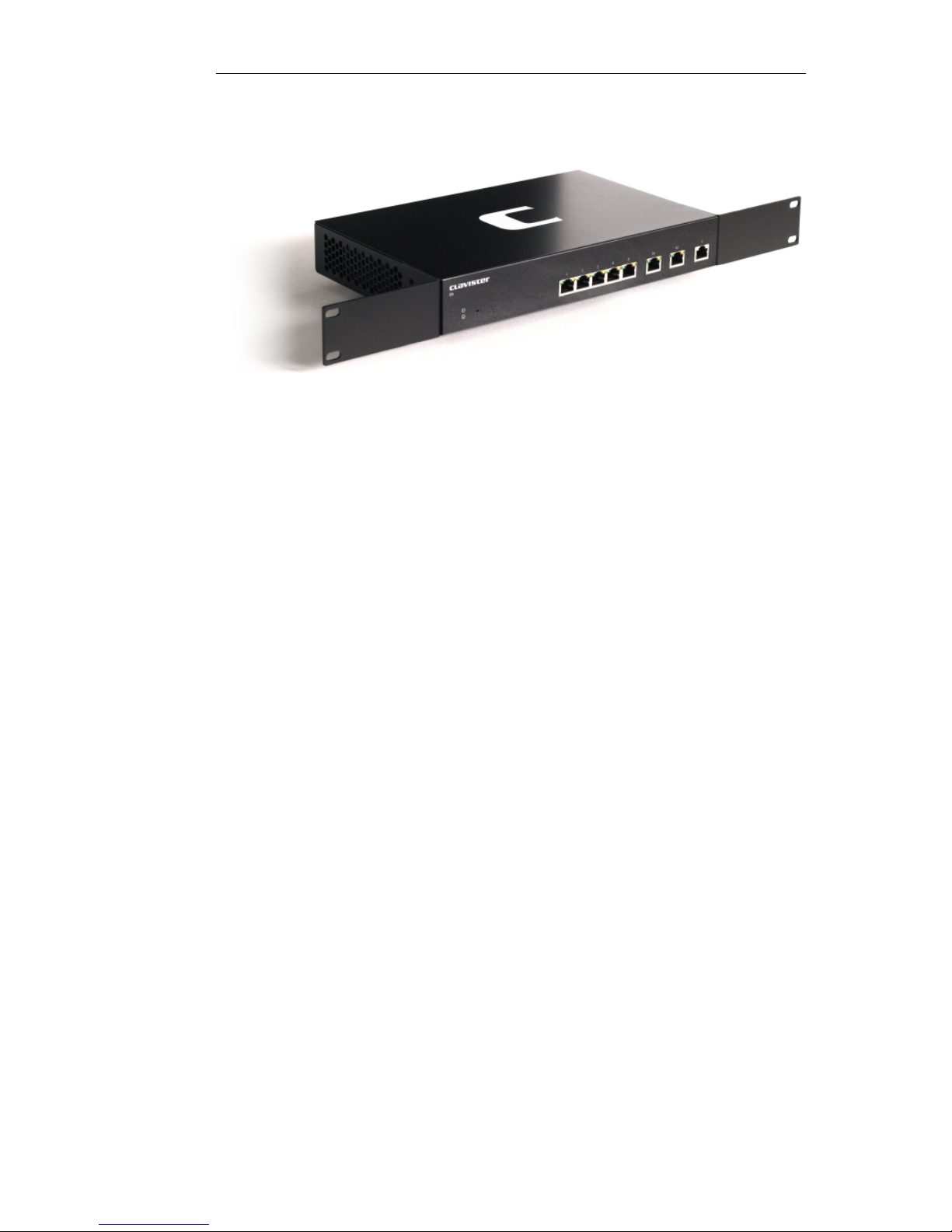
Repeat this for each side of the E5, so the brackets are mounted as shown below.
The E5 is now ready to be rack mounted.
Chapter 2: Installation
15

2.3. Local Console Port Connection
The local console port is the physical RJ45 RS-232 port on the far right-hand side front panel of
the E5.
Figure 2.1. The E5 Local Console Port
This local console port allows direct management connection to the appliance, either from a
separate computer running console emulation software or from a console terminal. Local
console access can then be used for both management of cOS Core with CLI commands or to
enter the boot menu in order to access E5 firmware loader options.
Tip: Skip the rest of this section if using the Web Interface
This rest of this section can be initially skipped if cOS Core setup is going to be done with
the cOS Core Web Interface since neither boot menu or CLI access will be needed.
Issuing CLI Commands
CLI commands can be issued via the local console port for both initial cOS Core setup as well as
for ongoing system administration.
The local console port need not be used if setup is done through a web browser as described in
Section 3.2, “Web Interface and Wizard Setup”. If the local console port is used for setup, no
password is initially needed and the CLI commands required are described in Section 3.4, “CLI
Setup”.
Note: Setting a local console password
A local console password need not be set. If this is the case, anyone with physical access
to the local console has full administrator rights.
If the E5 is not placed in a secure area, it is therefore advisable to set the console
password. This is done using the console boot menu and more detail on this can be
found in the separate cOS Core Administrators Guide.
Requirements for Local Console Connection
To get management access via the local console port, the following is needed:
• A terminal or a computer with a serial port and the ability to emulate a terminal (for example,
the open source puTTY software).
• The terminal console should have the following settings:
i. 9600 bps.
Chapter 2: Installation
16

ii. No parity.
iii. 8 bits.
iv. 1 stop bit.
v. No flow control.
• An RS-232 cable with appropriate terminating connectors.
Connection Steps
To connect a terminal to the local console port, perform the following steps:
1. Check that the console connection settings are configured as described above.
2. Connect one of the connectors on the cable directly to the local console port on the E5.
3. Connect the other end of the cable to a console terminal or to the serial connector of a
computer running console emulation software.
Connection Using SSH
An alternative to using the local console port for CLI access is to connect via a physical Ethernet
interface and using a Secure Shell (SSH) client on the management workstation to issue CLI
commands. This is discussed further in Section 3.1, “Management Workstation Connection”.
Chapter 2: Installation
17
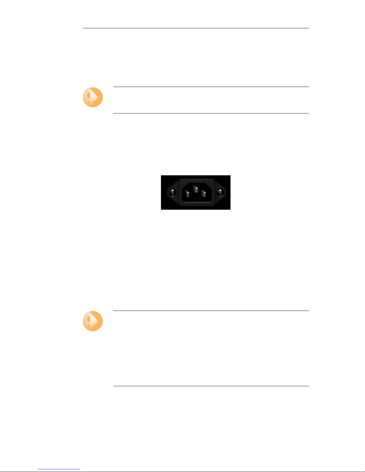
2.4. Connecting Power
This section describes connecting power. The E5 has a single internal 12V/2.5A AC to DC power
adaptor. As soon as power is applied, the E5 will boot-up and cOS Core will start.
Important
Please review the electrical safety information in Chapter 5, Safety Precautions.
Connecting AC Power
To connect power, follow these steps:
1. Plug the end of the power cord into the power inlet on the E5.
Figure 2.2. E5 Power Inlet Socket
2. Plug the power adapter into a suitable AC power outlet. There is no On/Off switch and the
unit will begin to boot up as soon as power is applied.
3. The E5 will boot up and cOS Core will start. After a brief period of time, cOS Core will be
initialized and the appliance is ready for configuration from a management workstation
using either the Web Interface or the Command Line Interface (CLI) as the management
interface.
Initial configuration is discussed in detail in Chapter 3, cOS Core Configuration.
Important: Protecting Against Power Surges
It is strongly recommended that the purchase and use of a separate surge protection
unit from a third party is considered. This is to ensure that computer hardware is
protected from damage by electrical power surges.
Surge protection is particularly important in locations where there is a heightened risk of
lightning strikes or where power grid spikes are more common.
Any surge protection unit should be installed exactly according to the manufacturer's
instructions since correct installation of such units is vital for them to be effective.
Chapter 2: Installation
18

2.5. Resetting to Factory Defaults
In some circumstances, it may be necessary to reset the E5 hardware to the state it was in when it
left the factory. This is known as a reset to factory defaults.
The recessed button next to the indicator LEDs on the front and left of the E5 can be used to
reset the E5 to its factory defaults.
Performing the Reset
The steps for a reset are as follows:
1. The progress of the reset can be followed using a local console connection. If that is
required, open a console display window connected to the E5 local console port.
2. Power off the hardware.
3. Push in the reset button with a suitable pointed tip tool.
4. Hold the button in and at the same time re-apply power to the appliance.
5. Continue holding in the button for at least 30 seconds longer after power is applied.
6. If a console was connected in step 1, the console output will now indicate that the hardware
has been reset to its factory defaults.
7. Release the button and the Clavister Security Gateway can now be configured through the
console as though it was brand new.
8. If a console password was set this will also be reset to the factory default of no password. If
required, the console password should be re-entered to protect the console.
Warning: Current configuration and cOS Core upgrades are lost
The factory defaults will include the default configuration and the original version of
cOS Core that the product left the factory with.
This means:
• The current cOS Core configuration will be lost but can be restored if a backup is
available.
• Any cOS Core upgrades that have been performed since the product left the factory
will be lost. An upgrade to a newer cOS Core version must be repeated.
Chapter 2: Installation
19

Chapter 2: Installation
20

Chapter 3: cOS Core Configuration
• Management Workstation Connection, page 21
• Web Interface and Wizard Setup, page 24
• Manual Web Interface Setup, page 32
• CLI Setup, page 48
• Installing a License, page 56
• Setup Troubleshooting , page 58
• Going Further with cOS Core, page 60
3.1. Management Workstation Connection
cOS Core Starts After Power Up
It is assumed that the E5 unit is now unpacked, positioned correctly and powered is applied. If
not, the earlier chapters in this manual should be referred to before continuing.
Clavister's cOS Core network security operating system is preloaded on the E5 and will
automatically boot up after power is applied. After boot-up is complete, an external
management computer workstation can be used to configure cOS Core.
The Default Management Interface
After first time startup, cOS Core automatically makes management access available on a single
predefined Ethernet interface and assigns the private IPv4 address 192.168.1.1 to it.
For the E5, the default management interface is any of the GESW interfaces since they are
connected together by a switch fabric. By convention, the first interface (labeled 1) is normally
used for management workstation connection.
cOS Core Setup Methods
Initial cOS Core software configuration can be done in one of the following ways:
21

• Through a web browser.
A standard web browser running on a standalone computer (also referred to as the
management workstation) can be used to access the cOS Core Web Interface. This provides an
intuitive graphical interface for cOS Core management. When this interface is accessed for
the first time, a setup wizard runs automatically to guide a new user through key setup steps.
The wizard can be closed if the administrator wishes to go directly to the Web Interface to
perform setup manually.
The wizard is recommended for its simplification of initial setup and is described in detail in
Section 3.2, “Web Interface and Wizard Setup”. The wizard assumes that connection to the
public Internet is one of the tasks to be performed and has a step for this.
• Through a terminal console using CLI commands.
Alternatively, the setup process can be performed using console CLI commands and this is
described in Section 3.4, “CLI Setup”. The CLI allows step by step control of setup and should
be used by administrators who fully understand both the CLI and setup process.
CLI access is possible in one of two ways:
i. CLI access can be remote, across a network to a physical Ethernet interface. This is a
similar to the connection used with the Web Interface and is also done using the default
management interface after powering up for the first time.
ii. Alternatively, CLI access can be through console emulation software running on a
separate management computer connected directly to the RJ45 local console port on
the E5 hardware. Direct console connection is described in Section 2.3, “Local Console
Port Connection”.
Network Connection Setup
For setup using the Web Interface via a web browser or the CLI via SSH, it is necessary to connect
an Ethernet interface on an external workstation computer to the default management Ethernet
interface on the E5.
The default management Ethernet interface for the E5 is any of the GESW interfaces (as a
convention, the first is normally used) and this is assigned the default IPv4 address of
192.168.1.1 by cOS Core. This interface should be connected to the same network as the
management workstation (or a network accessible from the workstation via one or more
switches).
Typically, the connection between the management workstation and the default management
interface is made via a switch using standard Ethernet cables, as shown in the illustration below.
Chapter 3: cOS Core Configuration
22
 Loading...