

Page 1

Cla-Val
Section # 2
Pilots and Accessories
Service Training Manual
“Simple solutions plus learning with a purpose”
Page 2

81
Section 2
Model Pilot Controls Section
X42N-2 Strainer & Needle 2-2
Valve Assembly
X43 Y Strainer 2-2
X44A Strainer and Orifice 2-2
Assembly
X46 Strainer 2-2
X47A Ejector 2-2
X52E Orifice Plate Assembly 2-2
X58C Restriction Assembly 2-2
X101 Position Indicator 2-2
X102 Flow Limiting Assembly 2-2
X103 Spring Lift 2-2
X105L Limit Switch Assembly 2-2
X117C/D Position Transmitter 2-2
Model Accessories
Section
CRD Pressure Reducing 2-1
CRA Reducing Pilot with 2-1
Remote Sensing
CRL Relief Pilot (55F & 55L) 2-1
CDHS-18 Differential Pilot 2-1
CDS6 Altitude Control 2-1
CFI-C1 Float Control 2-1
CFC2 External Float Control 2-1
CFM2 Modulating Float Control 2-1
CSM11 Solenoid Control 2-1
CV Speed Control 2-1
Pilot Regulator Spring Color Chart 2-1
Page 3

82
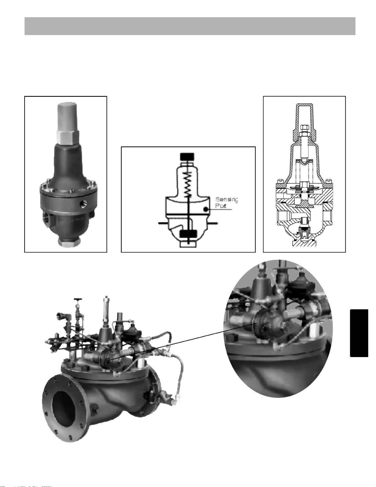
CRD – Cla-Val Reducing Pilot
The CRD is a Normally Open pilot and will shift to close on rise in outlet pressure. The CRD pilot is
used for most pressure reducing applications.
Normally Open – Shifts to closed on rise in
sensed pressure
Adjustment Ranges – 2-30, 15-75, 30-300 psi
Maximum Working Pressure 400 PSI
Pilot Controls
OUTIN
CRD
CRD
CRD
90-01/690-01
CRD
Schematic Symbol
Page 4

83
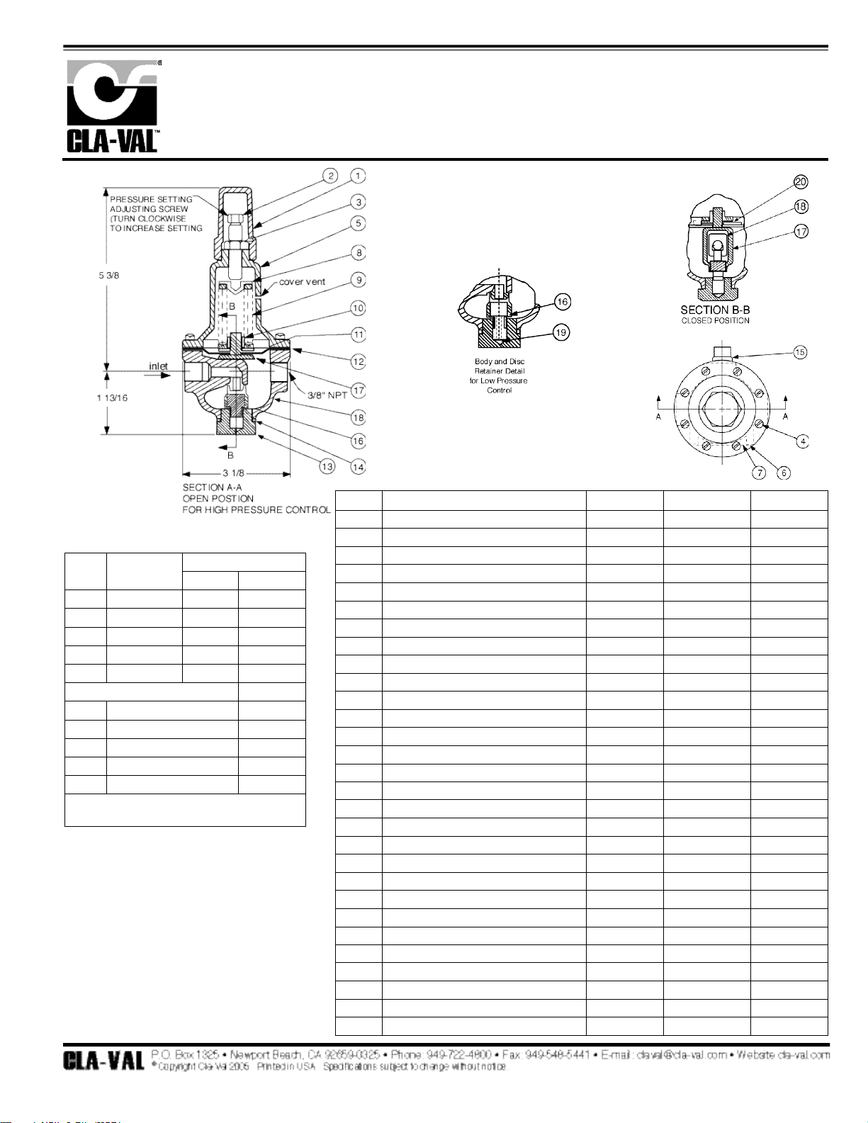
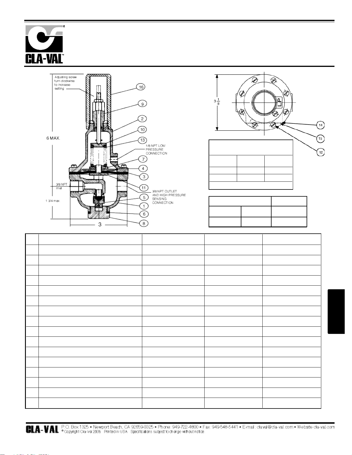
DESCRIPTION
The Cla-Val Model CRD Pressure Reducing Control automatically reduces
a higher inlet pressure to a lower outlet pressure. It is a direct acting, spring
loaded, diaphragm type control that operates hydraulically or pneumatically. It may be used as a self-contained valve or as a pilot control for a ClaVal main valve. It will hold a constant downstream pressure within very
close pressure limits.
OPERATION
The CRD Pressure Reducing Control is normally held open by the force of
the compression spring above the diaphragm; and delivery pressure acts
on the underside of the diaphragm. Flow through the valve responds to
changes in downstream demand to maintain a pressure.
INSTALLATION
The CRD Pressure Reducing Control may be installed in any position.
There is one inlet port and two outlets, for either straight or angle installation. The second outlet port can be used for a gage connection. A flow
arrow is marked on the body casting.
ADJUSTMENT PROCEDURE
The CRD Pressure Reducing Control can be adjusted to provide a delivery
pressure range as specified on the nameplate.
Pressure adjustment is made by turning the adjustment screw to vary the
spring pressure on the diaphragm. The greater the compression on the
spring the higher the pressure setting.
1. Turn the adjustment screw in (clockwise) to increase
delivery pressure.
2. Turn the adjustment screw out (counter-clockwise) to
decrease the delivery pressure.
3. When pressure adjustment is completed tighten jam nut on
adjusting screw and replace protective cap.
4. When this control is used, as a pilot control on a
Cla-Val main valve, the adjustment should be made
under flowing conditions. The flow rate is not critical,
but generally should be somewhat lower than normal
in order to provide an inlet pressure several psi higher
than the desired setting
SYMPTOM PROBABLE CAUSE REMEDY
Fails to open
when deliver
pressure lowers
No spring compression Tighten adjusting screw
Spring guide (8) is not in
place
Assemble properly
Yoke dragging on inlet
nozzle
Disassemble and reassemble
properly (refer to Reassembly)
Fails to close
when delivery
pressure rises
Spring compressed solid Back off adjusting screw
Mechanical obstruction
Disassemble and reassemble
properly (refer to Reassembly)
Worn disc
Disassemble remove and
replace disc retainer assembly
Yoke dragging on inlet
nozzle
Disassemble and reassemble
properly (refer to Reassembly)
Leakage from
cover vent hole
Damaged diaphragm Disassemble and replace
Loose diaphragm nut Remove cover and tighten nut
Damaged spring Disassemble and replace
CRD
MAINTENANCE
Disassembly
To disassemble follow the sequence of the item numbers assigned to
parts in the sectional illustration.
Reassembly
Reassembly is the reverse of disassembly. Caution: must be taken to
avoid having the yoke (17) drag on the inlet nozzle of the body (18).
Follow this procedure:
1. Place yoke (17) in body and screw the disc retainer
assembly (16) until it bottoms.
2. Install gasket (14) and spring (19) for 2-30 and 2-6.5 psi
range onto plug (13) and fasten into body. Disc retainer
must enter guide hole in plug as it is assembled. Screw
the plug in by hand. Use wrench to tighten only.
3. Place diaphragm (12) diaphragm washer (11) and belleville
washer (20) on yoke. Screw on hex nut (10).
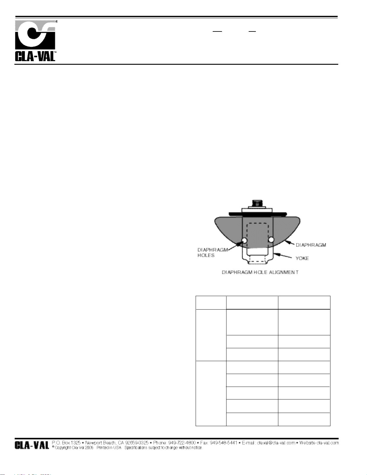
4. Hold the diaphragm so that the screw holes in the
diaphragm and body align. Tighten diaphragm nut with
a wrench. At the final tightening release the diaphragm
and permit it to rotate 5° to 10°. The diaphragm holes
should now be properly aligned with the body holes.
To check for proper alignment proceed as follows:
Rotate diaphragm clockwise and counterclockwise as far as possible.
Diaphragm screw holes should rotate equal distance on either side of
body screw holes ±1/8".
Repeat assembly procedure until diaphragm and yoke are properly
aligned. There must be no contact between yoke and body nozzle during its normal movement. To simulate this movement hold body and
diaphragm holes aligned. Move yoke to open and closed positions.
There must be no evidence of contact or dragging.
5. Install spring (9) with spring guide (8).
6. Install cover (5), adjusting screw (2) and nut (3), then cap (1).
Pressure Reducing Control
The approximate minimum flow rates given in the table are for the main valve
on which the CRD is installed.
Valve Size
Minimum Flow GPM
1 1/4" -3" 4"-8" 10"-16"
15-30 50-200 300-650
M O D E L
INSTALLATION / OPERATION / MAINTENANCE
N-CRD (R-5/05)
2
–
1
Page 5
84
*SUGGESTED REPAIR PARTS
CRD
Pressure Reducing Control
When ordering parts specify:
• All nameplate data
• Item Description
• Item number
PL-CRD (R-12/06)
PARTS LIST
Size
(inch)
Stock
Number
Adjustment Range
psi Ft of Water
3/8 71943-07A 2 - 6.5 4.5 - 15
3/8 71943-08J 2 - 30 4.5 - 69
3/8 71943-03K 15 - 75 35 - 173
3/8 71943-11C 20 - 105 46 - 242
3/8 71943-04H 30 - 300 69 - 692
Factory Set Pressure
PSI per Turn
2 - 6.5 set @ 3.5 psi .61
2 - 30 set @ 10 psi 3.0
15 - 75 set @ 20 psi 9.0
20 - 105 set @ 60 psi 12.0
30 - 300 set @ 60 psi 27.0
*Approximate-Final Adjustment should be
with a pressure gauge and with flow.
Item Description Material Part Number List Price
1 Cap PL 67628J
2 Adjusting Screw BRS 7188201D
3 Jam Nut (3/8-16) SS 6780106J
4* Machine Screw (Fil.Hd.) 8 Req'd 303 6757821B
5 Cover BRS C2544K
6 Nameplate Screw SS 67999D
7 Nameplate BRS C0022001G
8 Spring Guide 302 71881H
9 Spring (15-75 psi) CHR/VAN 71884B
Spring (2 - 6.5 psi) SS 82575C
Spring (2 - 30 psi) SS 81594E
Spring (20 - 105 psi) CHR/VAN 20561901H
Spring (30 - 300 psi) CHR/VAN 71885J
10 Hex Nut 303 71883D
11 Diaphragm Washer 302 71891G
12 Diaphragm NBR C6936D
13 Plug, Body BRS V5653A
14* Gasket Fiber 40174F
15 Plug BRS 6766003F
16* Disc Retainer Assy. (15 - 75 psi) BZ/Rub C5256H
Disc Retainer Assy. (2 - 30 psi) BZ/Rub C5255K
Disc Retainer Assy. (20 - 105 psi) BZ/Rub 20561901H
Disc Retainer Assy. (30 - 300 psi) BZ/Rub C5256H
17 Yoke VBZ V6951H
18 Body & 1/4" Seat Assy BR/SS 8339702G
19* Bucking Spring (2 - 30 psi) 302 V0558G
20 Belleville Washer STL 7055007E
* Repair Kit (No Bucking Spring)
Buna®-N
9170003K
* Repair Kit (with Bucking Spring)
Buna®-N
9170001D
Page 6
85
CRA – Cla-Val Reducing Pilot with a remote sensing port
The CRA is similar to a CRD but it also has an extra feature; it has a remote sense port. The CRA
is a Normally Open pilot and will shift to close on rise in pressure. The CRA pilot is used for pressure reducing applications where a remote pressure needs to be sensed.
Normally Open – Shifts to close on rise in
sensed pressure.
Adjustment Ranges – 2-35, 15-75, 30-300 psi
Maximum Working Pressure 400 PSI
OUT
IN
CRA
CRA
CRA
CRA
52-03
2
–
1
Schematic Symbol
Pilot Controls
Page 7
86
DESCRIPTION
The CRA Pressure Reducing Control automatically reduces a higher inlet
pressure to a lower outlet pressure. It is a direct acting, spring loaded,
diaphragm type valve that operates hydraulically or pneumatically and is
designed to sense pressure from a remote point. It may be used as a selfcontained valve or as a pilot control for a Cla-Val main valve. It will hold a
constant downstream pressure at the remote sensing point within very
close pressure limits.
OPERATION
The CRA Pressure Reducing Control is normally held open by the force
of the compression spring above the diaphragm; delivery pressure acts on
the underside of the diaphragm. Flow through the valve responds to
changes in pressure at the the sensing point.
INSTALLATION
The CRA Pressure Reducing Control may be installed in any position.
There is one inlet port and two outlets, for either straight or angle installation. The second outlet port can be used for a gauge connection. A flow
arrow is marked on the body casting.
ADJUSTMENT PROCEDURE
The CRA Pressure Reducing Control can be adjusted to provide a delivery pressure range as specified on the nameplate.
Pressure adjustment is made by turning the adjustment screw to vary the
spring pressure on the diaphragm. The greater the compression on the
spring the higher the pressure setting.
1. Turn the adjustment screw in (clockwise) to increase delivery
pressure.
2. Turn the adjustment screw out (counter-clockwise) to decrease
the delivery pressure. When pressure adjustment is completed,
tighten jam nut on adjustment screw and replace protective cap.
Flow rates are not critical during pressure setting. The approximate min imum flow rates given in the table are for the main valve on which the CRA
is installed.
Valve Size 1 1/4"-3" 4"-8" 10"-16"
Minimum Flow GPM 15-30 50-200 300-650
MAINTENANCE
Disassembly
To disassemble follow the sequence of the item numbers assigned to
parts in the sectional illustration.
Reassembly
Reassembly is the reverse of disassembly. Caution must be taken to
avoid having the yoke (17) drag on the inlet nozzle of the body (18).
Follow this procedure:
1. Place yoke (17) in body and screw the disc retainer assembly
(16) until it bottoms.
2. Install gasket (14) and spring (19) for 2-30 psi range onto plug
(13) and screw into body. Disc retainer must enter guide hole in
plug as it is assembled. Screw the plug in by hand. Use wrench
to tighten only.
3. Place gasket (25) and powertrol body (21) on yoke extension
(17). Refer to sectional view for proper reassembly of (21) onto
body (18).
4. Place lower diaphragm washer (24), "O" ring (22), diaphragm
(12), upper diaphragm washer (11), and belleville washer (20) on
yoke extension (17). Screw on diaphragm nut (10) finger tight.
5. Place two machine screws (4) through (21) (25) and screw into
body (18). Do not include the diaphragm (12) in this operation.
This holds parts aligned for next step, and allows the diaphragm
to move and be properly located during tightening of nut (10).
6. Hold the diaphragm so that screw holes in the diaphragm (12)
SYMPTOM PROBABLE CAUSE REMEDY
Fails to open when
pressure lowers
No spring compression Tighten adjusting
screw
Mineral buildup on yoke
extension (17)
Disassemble and
clean part,
Replace "O" rings
(22) and (23).
Damaged spring Disassemble and
replace.
Spring guide (8) is not in
place
Disassemble and
place guide (8) on
top of spring (9).
Yoke dragging on inlet
nozzle
Disassembled
and reassemble
use procedure.
Fails to close when
delivery pressure rises
Spring compressed
Back off adjusting
screw
Mineral deposit on yoke
extension (17)
Disassemble and
clean part.
Replace "o" rings
(22) and (23).
Mechanical obstruction
Disassemble and
remove obstruction
Worn disc
Disassemble,
remove and
replace disc
retainer assembly. (16)
Yoke dragging on inlet
nozzle
Refer to paragraph 6
Damaged diaphragm (12)
Disassemble and
replace
Loose diaphragm nut (10)
Remove cover
and tighten nut
REMOTE SENSING TYPE
CRA
Leakage from cover
vent hole
M O D E L
INSTALLATION / OPERATION / MAINTENANCE
N-CRA (R-5/05)
and powertrol body (21) align. Tighten diaphragm nut (10) with a wrench.
At the final tightening release the diaphragm and permit it to rotate
approximately 5° to 10°. The diaphragm holes should now be properly
aligned with the body holes.
To check for proper alignment proceed as follows:
Rotate diaphragm clockwise and counterclockwise as far as possible.
Diaphragm screw holes should rotate equal distance on either side of
powertrol body screw holes ±1/8".
Repeat assembly procedure until diaphragm and yoke are properly
aligned. There must be no contact between yoke and body nozzle during
its normal opening and closing movement. To simulate this movement
hold powertrol body and diaphragm holes aligned. Move yoke to open
and closed positions. There must be no evidence of contact or dragging.
7. Remove machine screws per step 5.
8. Install spring (9) with spring guide (8) on top of spring.
9. Install cover (5) using eight machine screws (4).
10. Replace adjusting screw (2) and nut (3), then cap (1).
Pressure Reducing Control
Page 8

87
2
–
1
* Suggested Repair Parts
REMOTE SENSING TYPE
SIZE
(inch)
STOCK
NUMBER
SEAT
DIA
ADJ.
RANGE
(psi)
3/8 79744-04B 1/4 30-300
3/8 79744-06G 1/4 2-30
Factory set pressure:
PSI*per turn
30-300 set @ 60 psi 27.0
2-30@ 10 psi 3.0
3/8 79744-03D 1/4 15-75
Pressure Reducing Control
CRA
When ordering parts specify:
• All nameplate data
• Description
• Item number
* Approximate - Final adjustment should
be made with a pressure gauge and
with flow.
15-75 set @ 20 psi 9.0
1
2
3
4*
5
6
7
8
9
10
11
12*
13
14*
15
16*
17
18
19*
20
21
22*
23*
24
25
*
*
Cap
Adjusting Screw
Jam Nut, 3/8—16
Machine Screw 10-32 x 1-1/4"(Fil.Hd.) (8 required)
Cover
Nameplate Screw
Nameplate
Spring Guide
Spring
(15-75 psi)
(30-300 psi)
(2-30 psi)
Hex Nut 5/16 - 18
Diaphragm Washer (upper)
Diaphragm
Plug, Body
Gasket
Plug, 3/8 NPT
Disc Retainer Assy (15-75 psi & 30-300 psi)
Disc Retainer Assy (2-30 psi)
Yoke
Body & Seat Assy, Seat only 1/4"
Bucking Spring (Required with 2-30 psi)
Belleville Washer
Powertrol Body
O-Ring
O-Ring
Diaphragm Washer (lower)
Gasket
Repair Kit (no Bucking Spring) Item 19
Repair Kit (with Bucking Spring) Item 19
PL
BRS
303
SS
BRS
SS
BRS
302
CHR VAN
CHR VAN
SS
303
302
NBR
BRS
FIB
BRS
BR/RUB
BR/RUB
VBZ
BS
302
STL
BRS
NBR
NBR
BRS
NBC
Buna®-N
Buna®-N
67628J
7188201D
6780106J
6757874A
C2544K
67999D
C002201G
71881H
71884B
71885B
81594E
71883D
71891G
C6936D
V5653A
40174F
6766003F
C5256H
C5255K
C1799A
8339701J
VO5586
7055007E
C3388A
00708J
00746J
C1804J
8059401D
9170003K
9170001D
ITEM DESCRIPTION MATERIAL PART NUMBER LIST PRICE
PL-CRA (R-11/06)
PARTS LIST
Page 9

88
OUT
IN
CRL – Cla-Val Relief Pilot
The Cla-Val CRL pilot is a Normally Closed pilot that shifts to Open on rise in sensed pressure. The
CRL is used for most pressure relief or pressure sustaining applications.
Normally Closed - Shifts to open on rise
in sensed pressure
Adjustment Ranges
0-75, 20-200,100-300 psi
Contact Cla-Val for higher ranges
Maximum Working Pressure 400 PSI
CRL
CRL
CRL
CRL
50-01/650-01
Schematic Symbol
Pilot Controls
Page 10

89
2
–
1
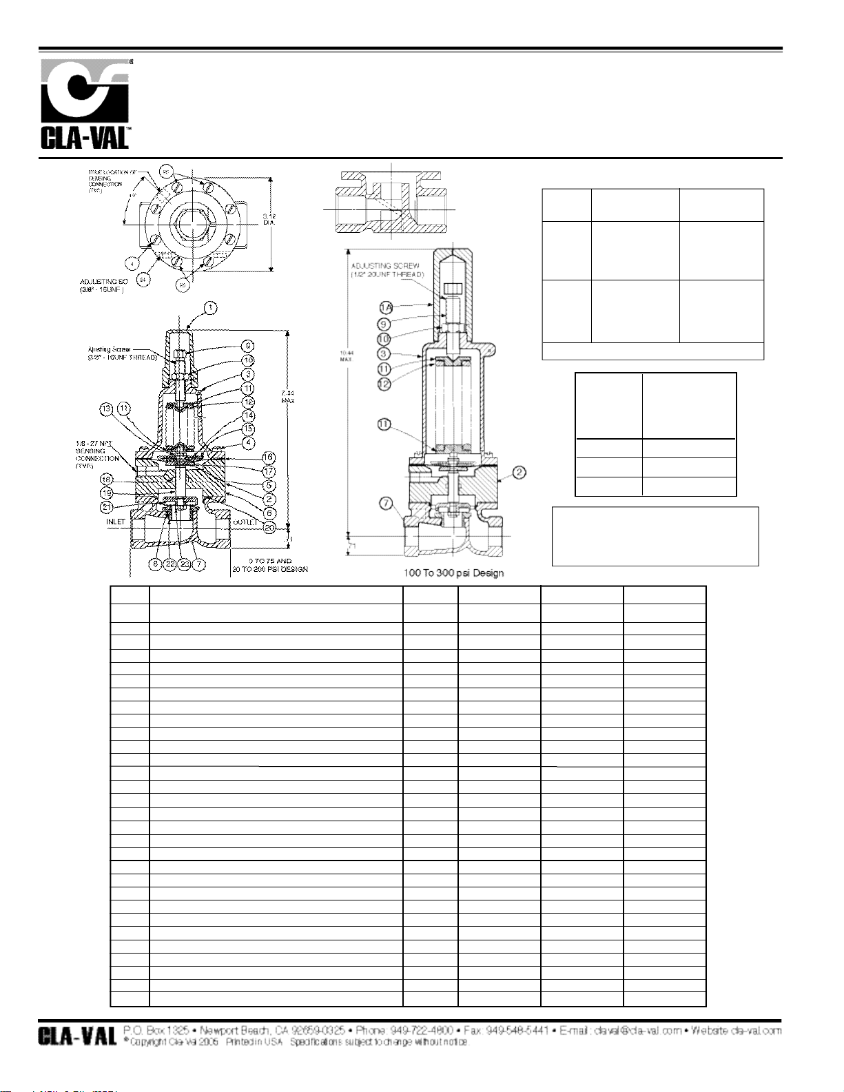
DESCRIPTION
The CRL Pressure Relief Control is a direct acting, spring loaded,
diaphragm type relief valve. It may be used as a self-contained valve or as
a pilot control for a Cla-Val Main valve. It opens and closes within very
close pressure limits.
INSTALLATION
The CRL Pressure Relief Control may be installed in any position. The
control body (7) has one inlet and one outlet port with a side pipe plug (24)
at each port. These plugs are used for control connections or gauge applications. The inlet in the power unit body (6) is the sensing line port. A flow
arrow is marked on the body casting.
OPERATION
The CRL Pressure Relief Control is normally held closed by the force of the
compression spring above the diaphragm; control pressure is applied
under the diaphragm.
When the controlling pressure exceeds the spring setting, the disc is lifted
off its seat, permitting flow through the control.
When controlling pressure drops below spring setting, the spring returns
the control to its normally closed position.
ADJUSTMENT PROCEDURE
The CRL Pressure Relief Control can be adjusted to provide a relief setting
at any point within the range found on the nameplate.
Pressure adjustment is made by turning the adjustment screw (9) to vary
the spring pressure on the diaphragm. Turning the adjustment screw clockwise increases the pressure required to open the valve. Counterclockwise
decreases the pressure required to open the valve.
When pressure adjustments are complete the jam nut (10) should be tightened and the protective cap (1) replaced. If there is a problem of tampering, lock wire holes have been provided in cap and cover. Wire the cap to
cover and secure with lead seal.
DISASSEMBLY
The CRL Pressure Relief Control does not need to be removed from the
line for disassembly. Make sure that pressure shut down is accompanied
prior to disassembly. If the CRL is removed from the line for disassembly
be sure to use a soft jawed vise to hold body during work.
Refer to Parts List Drawing for Item Numbers.
1. Remove cap (1), loosen jam nut (10) and turn adjusting
screw counterclockwise until spring tension is relieved.
2. Remove the eight screws (4) holding the cover (3) and
powerunit body (6). Hold the cover and powerunit together
and place on a suitable work surface.
See NOTE under REASSEMBLY.
3. Remove the cover (3) from powerunit body (6). The spring
(12) and two spring guides (11).
4. Remove nut (13) from stem (19) and slide off the belleville washer
(14), the upper diaphragm washer (15) and the diaphragm (16).
5. Pull the stem (19) with the disc retainer assembly (21) through the
bottom of powerunit. The lower diaphragm washer (17) will slide off
of stem top.
6. Remove jam nut (23) and disc retainer assembly (21) from stem.
Use soft jawed pliers or vise to hold stem. The polished surface of
stem must not be scored or scratched.
7. The seat (22) need not be removed unless it is damaged. If removal
is necessary use proper size socket wrench and turn counterclockwise.
Note: Some models have an integral seat in the body (7).
INSPECTION
Inspect all parts for damage, or evidence of cross threading. Check
diaphragm and disc retainer assembly for tears, abrasions or other da mage. Check all metal parts for damage, corrosion or excessive wear.
REPAIR AND REPLACEMENT
Minor nicks and scratches may be polished out using 400 grit wet or dry
sandpaper fine emery or crocus cloth. Replace all O-rings and any damaged parts.
When ordering replacement parts, be sure to specify parts list item number and all nameplate data.
REASSEMBLY
In general, reassembly is the reverse of disassembly. However, the following steps should be observed:
1. Lubricate the O-Ring (18) with a small amount of a good grade of
waterproof grease, (Dow Corning 44 medium grade or equal).
Use grease sparingly and install O-ring in powerunit body (6).
2. Install stem (19) in powerunit body (6). Use a rotating motion with
minimum pressure to let stem pass through O-ring.
Do Not Cut O-Ring.
3. Install O-ring (5) at top of stem (19). Place lower diaphragm
washer (17) on the stem with the serrated side up. Position
diaphragm (16), upper diaphragm washer (15), with serration down,
and belleville washer (14) with concave side down.
4. Position powerunit body (6) as shown on parts list drawing (top view).
5. Continue reassembly as outlined in disassembly steps 1 through 3.
Pressure Relief Control
CRL
Note: Item (4) Screw will have a quantity of 8 for the 0-75 and 20-200psi
design and a quantity of 4 for the 100-300psi design. Item (25) Screw is
used on the 100-300psi design only. Install item (25), before item (4) for
preload of item (12) spring.
SYMPTOM PROBABLE CAUSE REMEDY
Fails to open. Controlling pressure
too low.
Back off adjusting
screw until valve
opens.
Fails to open with
spring compression
removed.
Mechanical obstruction, corrosion, scale
build-up on stem.
Disassemble,
locate,and remove
obstruction, scale.
Leakage from cover
vent hole when controlling pressure is
applied.
Diaphragm Damage Disassembly replace
damaged
diaphragm.
Fails to close with
spring compressed.
Mechanical obstruction.
Disassemble, locate
and remove
obstruction.
Fails to close. No spring compres-
sion.
Re-set pressure
adjustment.
Loose diaphragm
assembly.
Tighten upper
diaphragm washer.
M O D E L
INSTALLATION / OPERATION / MAINTENANCE
N-CRL (R-8/05)
Page 11
90
1/2" & 3/4" PRESSURE RELIEF CONTROL
CRL
When ordering parts please specify:
1. All Nameplate Data
2. Item Part Number
3. Item Description
CRL
RANGE PSI
A
PPROX
. I
NCREASE
FOR EACH CLOCK
-
WISE TURN OF
ADJUSTING SCREW
0 to 75 8.5 PSI
20 to 200 28.0 PSI
100 to 300 18.0 PSI
SIZE
1/2"
1/2"
1/2"
3/4"
3/4"
3/4"
SPRING
RANGE
0-75 PSI
20-200 PSI
100-300 PSI
0-75 PSI
20-200 PSI
100-300 PSI
PART
NUMBER
79222-01E
79222-02C
82809-01D
79229-01K
79229-02H
86005-01E
For 100-450 PSI Contact Factory
Body with
integral Seat
1
1A
2
3
4*
5*
6
7
8*
9
10
11
12
13
14
15
16*
17
18*
19
20*
21*
22
23
24
25*
Cap
Cap 100 to 300 psi Design
Nameplate
Cover
Screw Fil.Hd.10-32 x 1.88
0-Ring
Body, Powerunit
1/2" Body
3/4" Body
0-Ring, Seat
Screw, Adjusting
Nut Hex (Locking)
Guide, Spring
Spring,
Nut, Stem, Upper
Washer, Belleville
Washer, Diaphragm (upper)
Diaphragm
Washer, Diaphragm (lower)
0-Ring, Stem
Stem
0-Ring, Body
Retainer Assembly, Disc
Seat
Nut, hex, Stem, Lower
Pipe Plug
Screw Fil.Hd, 10-32 x 2.25 (Qty 4 on 100-300 psi)
FACTORY SET POINT
REPAIR KIT*
Plastic
Plastic
Brass
Bronze
303 SS
Rubber
Bronze
Bronze
Bronze
Rubber
Brass
303 SS
303 SS
CHR/VAN
Bronze
Steel
303 SS
Rubber
303 SS
Rubber
303 SS
Rubber
303 SS
303 SS
Bronze
Bronze
303 SS
0-75
67628J
1257601D
--
C2544K
6757867E
00902H
7920504D
C7928K
C9083B
00718H
7188201D
6780106J
71881H
71884B
73034B
7055007E
71891G
C1505B
45871B
00746J
8982401F
00767E
C8964D
62187A
6779806G
6784701C
6757867E
50 PSI
9170007A
20-200
67628J
1257601D
--
C2544K
6757867E
00902H
7920504D
C7928K
C9083B
00718H
7188201D
6780106J
71881H
71885J
73034B
7055007E
71891G
C1505B
45871B
00746J
8982401F
00767E
C8964D
62187A
6779806G
6784701C
6757867E
60 PSI
9170007A
100-300
1257601D
1257601D
--
44587E
6757867E
00902H
7920504D
C7928K
C9083B
00718H
7188201D
6780106J
1630301J
1630201A
73034B
7055007E
71891G
C1505B
45871B
00746J
8982401F
00767E
C8964D
62187A
6779806G
6784701C
6757867E
100 PSI
9170007A
Item Material Part Number
Part Number
Part Number
Description
PL-CRL (R-12/05)
PARTS LIST
Page 12
91
55F – Cla-Val Relief Pilot with external mounted sense line
The Cla-Val 55F pilot is a Normally Closed pilot that shifts to Open on rise in sensed pressure. It is
like the CRL but has an extra feature; sense tubing is connected from the inlet of the pilot to the
sensing port of the pilot. The 55F is often used as a stand-alone direct acting pressure relief valve.
OUTIN
55F/55L
55F
55F/55L
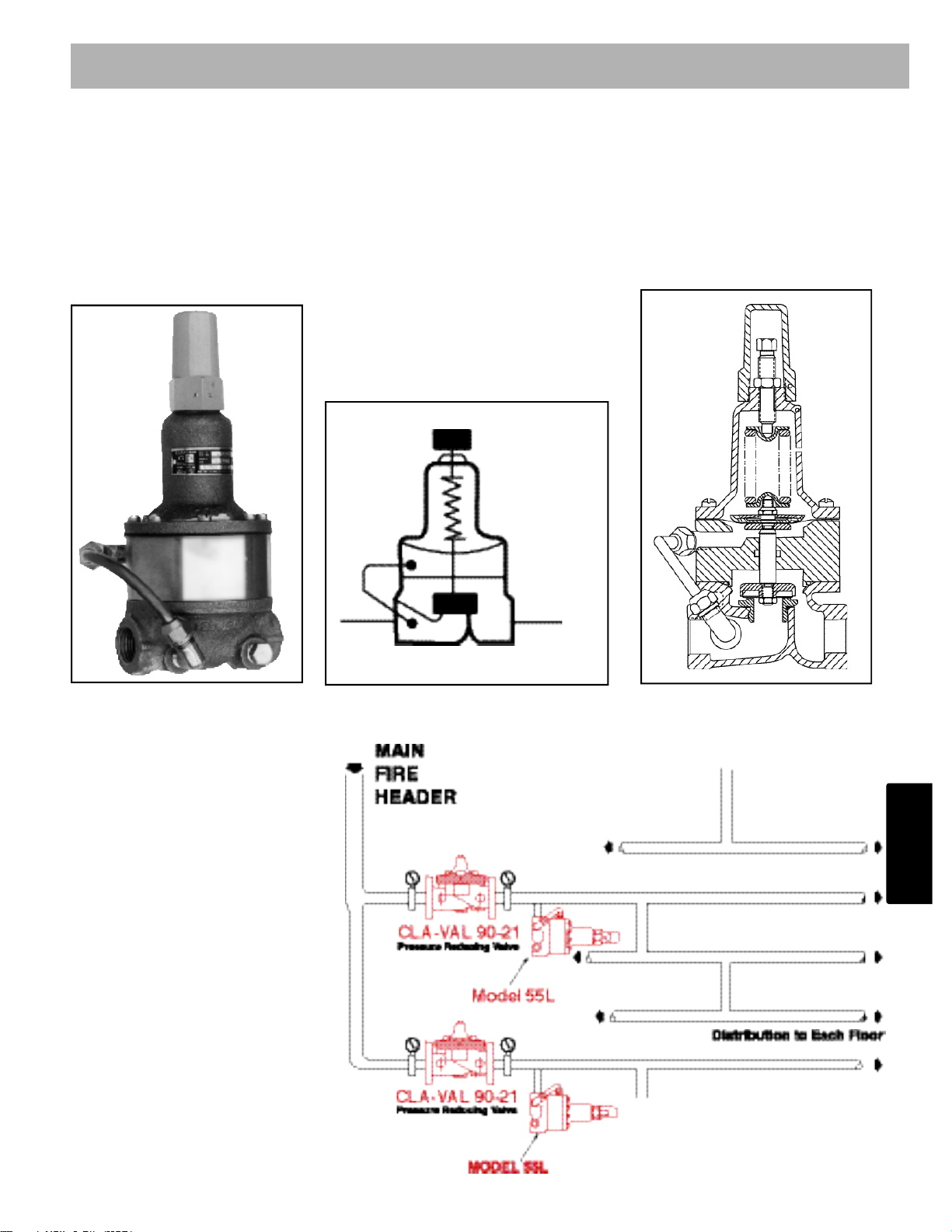
Fire Protection System Service
Using the Model 55L in a fire protection system or other closed type
system, prevents pressure build-up
whenever line pressure exceeds the
setting of the spring. The valve will
relieve excess pressure to atmosphere preventing damage to the
distribution network.
Typical Applications
2
–
1
Normally Closed - Shifts to open
on rise in sensed pressure
Adjustment Ranges
0-75,20-200,100-300 psi
Maximum Working Pressure 400 PSI
Schematic Symbol
Pilot Controls
Section 2 - 1
Page 13

92
CRL & 55F
Pressure Relief Valves
Dimensions
(In Inches)
55F Model
MODELS
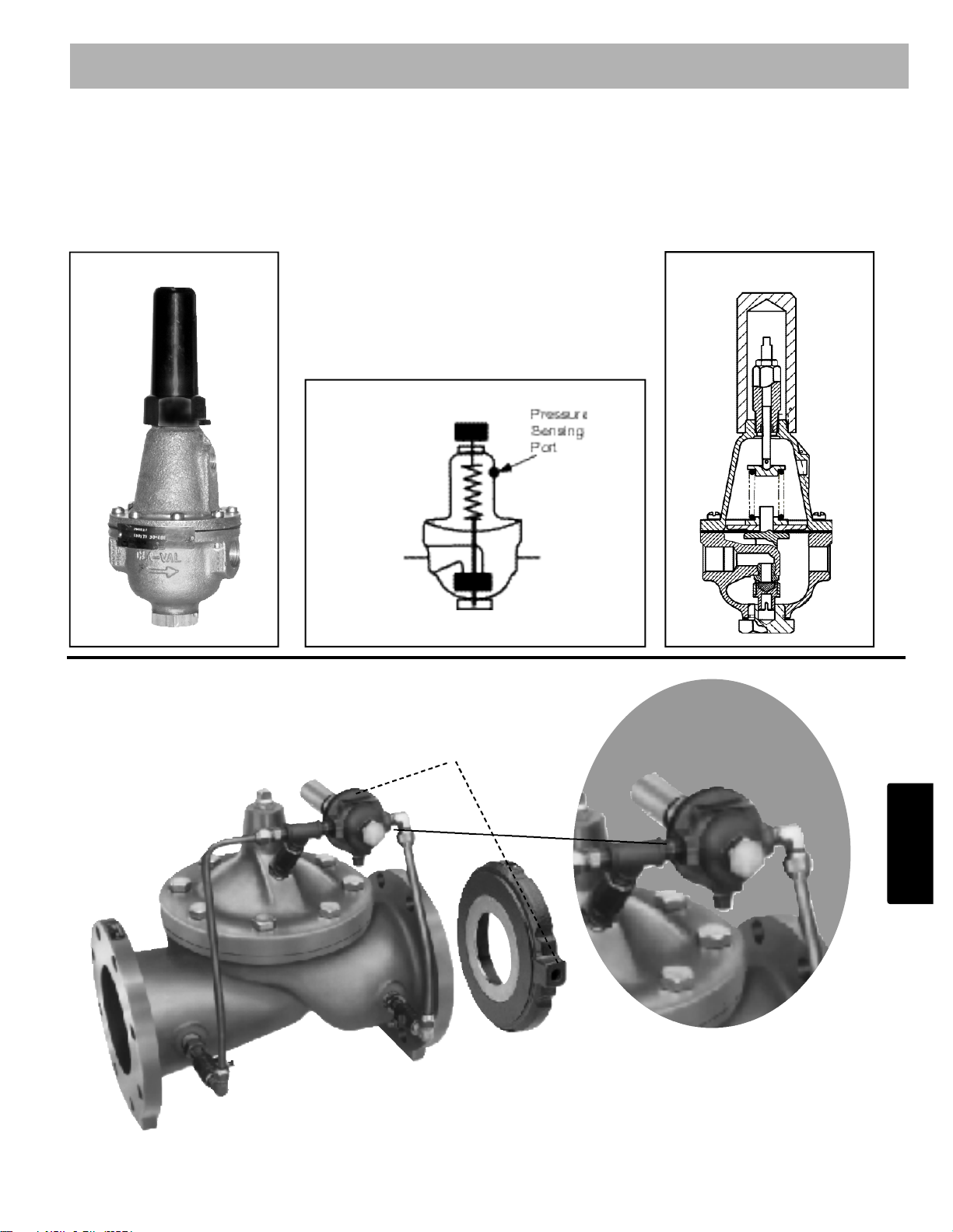
• Direct Acting - Precise Pressure Control
• Positive Dependable Opening
• Drip Tight Closure
• No Packing Glands or Stuffing Boxes
• Sensitive to Small Pressure Variations
The Cla-Val Model CRL and 55F Pressure Relief Valves are direct-acting, spring loaded, diaphragm type relief valves. Often used as pilot controls for Cla-Val Hytrol valves, they can also be used as self-contained
pressure relief valves. These valves may be installed in any position and
open and close within very close pressure limits.
The Model CRL and 55F are normally held closed by the force of the
compression spring above the diaphragm. Control pressure is applied
under the diaphragm. When the controlling pressure exceeds the spring
setting, the disc is lifted off its seat, permitting flow through the control.
When control pressure drops below the spring setting, the spring forces
the control back to its normally closed position. The controlling pressure
is applied to the chamber beneath the diaphragm through an external
tube on the Model 55F and a sensing port on the CRL.
Pressure adjustment is simply a matter of turning the adjusting screw to
vary the spring pressure on the diaphragm. The CRL & 55F
are available in three pressure ranges: 0 to 75 psi, 20 to 200 psi, and
100 to 300 psi. To prevent tampering, the adjustment cap can be wire
sealed by using the lock wire holes provided in the cap and cover.
Note: Also Available in Seawater Service Material
Page 14
93
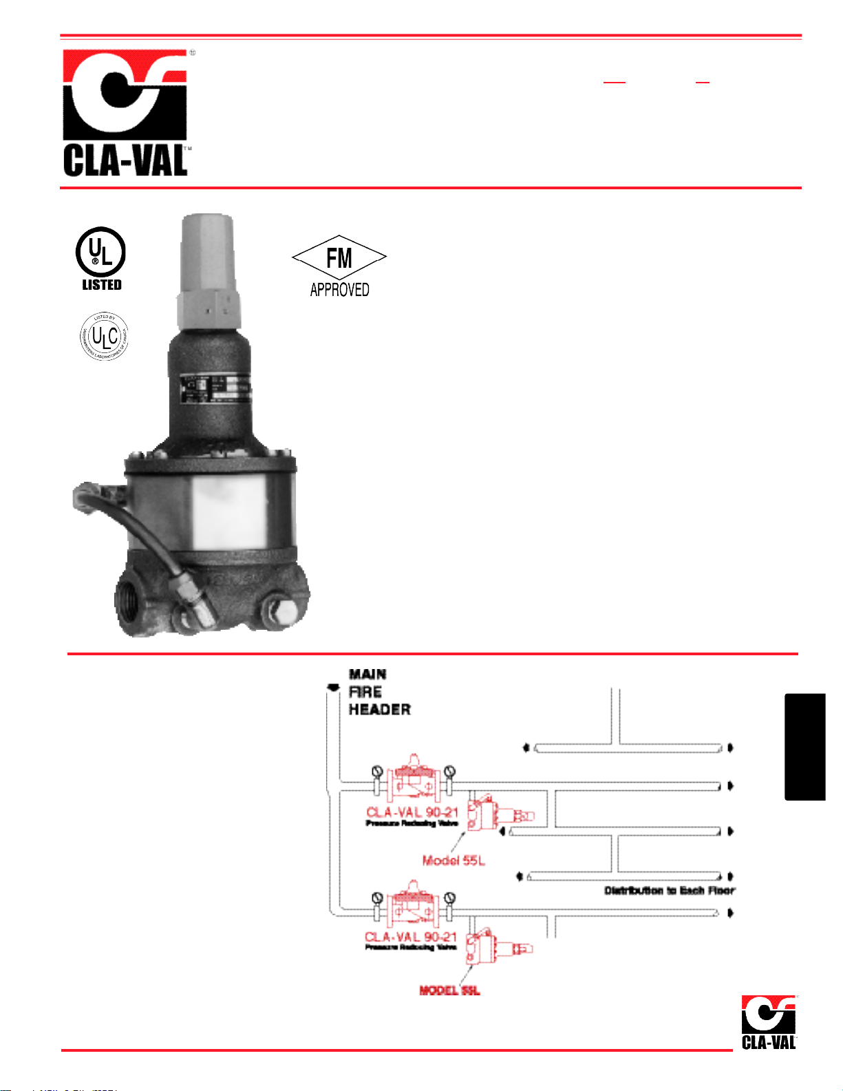
Fire Protection System Service
Using the Model 55L in a fire protection system or other closed type
system, prevents pressure build-up
whenever line pressure exceeds the
setting of the spring. The valve will
relieve excess pressure to atmosphere preventing damage to the
distribution network.
55L
Pressure Relief Valve
Typical Applications
• UL Listed
• Factory Mutual Approved
• Direct Acting - Precise Pressure Control
• Positive Dependable Opening
• Drip Tight Closure
• No Packing Glands or Stuffing Boxes
• Sensitive to Small Pressure Variations
The Cla-Val Model 55L (UL Listed FM approved) Pressure Relief Valve
is a direct-acting, spring loaded, diaphragm type relief valve. The valve
may be installed in any position and will open and close within very close
pressure limits.
The Model 55L is normally held closed by the force of the compression
spring above the diaphragm. When the controlling pressure applied
under the diaphragm exceeds the spring setting, the disc is lifted off its
seat, permitting flow through the control. When control pressure drops
below the spring setting, the spring forces the control back to its normally closed position. The controlling pressure is applied to the chamber
beneath the diaphragm through an external tube on the 55L.
Pressure adjustment is simply a matter of turning the adjusting screw to
vary the spring load on the diaphragm. The 55L is available in two pressure ranges; 0 to 75 psi, 20 to 200 psi. To prevent tampering, the adjustment cap can be wire sealed by using the lock wire holes provided in the
cap and cover.
Note: Also Available in Seawater Service Material
MODEL
2
–
1
Page 15

94
Note:
See E-X140 Locking Security Cap
S i z e 1/2" & 3/4" T h r e a d e d
Temperature Range Wa t e r , Air: to 180°F Max.
M a t e r i a l s
Body & Cover: Cast Bronze ASTM B62
Cast Aluminum 356-T6
Stainless Steel ASTM A 7 4 3 C 7 - 1 6 7 A
Tr i m : Brass & Stainless Steel 303
R u b b e r : B u n a - N®Synthetic Rubber
Pressure Ratings Cast Bronze 400 psi Max.
Cast Aluminum 275 psi Max.
Stainless steel 400 psi Max.
Other Materials Available on special order
Adjustment Ranges 0 t o 75 psi
2 0 t o 200 psi
1 0 0 t o 300 psi
When Ordering, Please Specify
1. Catalog No. CRL & 55F 2. Valve Size 3. Adjustment Range Desired 4. Optional Materials 5.Optional Security Cap
Specifications
Flow Loss Chart (Full Open Valve)
CRL Basic Valve Dimensions
(In Inches)
100 to 300 psi Design
CRL & 55F Approximate Increase
Range For Each Clockwise Turn
PSI Of Adjusting Screw
0 to 75 8.5 psi
20 to 200 28.0 psi
100 to 300 18.0 psi
5 10 15 20 30
1/2" 6 0.7 2.7 6 11
3/4" 8.5 0.3 1.4 3.1 5.5
Valve
Size
C
v
Factor
Flow of Water - gpm
E-CRL/55F (R-6/06)
Represented By:
0 to 75 and 20 to 200 psi Design
X140-1
Locking
Security
Cap
OPTIONAL X140 SECURITY CAP
• Controlled Security for Pilot Control Adjustment
• Long Life Stainless Steel Construction
• Tamper-Resistant Design
• X140 Customer Supplied Padlock
• X140-1 Key and Six Pin Cylinder Lock Supplied
Page 16
95
OUTIN
CDHS18
CDHS18
CDHS18
CDHS-18 Differential Control Valve
is a normally open, spring loaded, diaphragm type valve that operates hydraulically and is designed
to close on a rising differential pressure. When used as a pilot control with Cla-Val Valves, it acts as a
flow limiting control.
CDHS18
40-01/640-01
2
–
1
Sensing Line
Schematic Symbol
Pilot Controls
Normally Closed - Shifts to open
on rise in sensed pressure
Adjustment Ranges
30-480 psi differential
Page 17
96
DESCRIPTION
The Cla-Val CDHS-18 Differential Control Valve is a normally open, spring
loaded, diaphragm type valve that operates hydraulically and is designed
to close on a rising differential pressure. When used as a pilot control with
Cla-Val Valves, it acts as a flow limiting control.
INSTALLATION
The Differential Control may be installed in any position. There is one in l e t
port and two outlet ports in the body for either straight or angle ins t a l l a t i o n .
The outlet port senses the high pressure or inlet to the differential p r o d u c i n g
device. One of the outlet ports can be used for a gauge connection.
The port above the diaphragm (located in the control cover) is used to
sense the low pressure or outlet side of the differential producing device. A
flow arrow is marked on the body casting.
OPERATION
The Differential Control is normally held open by the compression spring
and the sensing pressure above the diaphragm. When the rate of flow
through the main valve increases, the sensing pressure above the
diaphragm of the control decreases and the higher pressure at the outlet
port closes the control; which, in turn, closes the main valve. When the
rate of flow through the main valve decreases, the sensing pressure
above the diaphragm increases. This opens the control and in turn opens
the main valve. This action causes the main valve to modulate, limiting the
flow rate to the setting of the control.
ADJUSTMENT
The Differential Control Valve can be adjusted to limit the rate of flow as
specified on the data plate. Rate of flow adjustment is made by turning the
adjustment screw to vary the spring pressure on the diaphragm. The
greater the compression on the spring the higher the flow rate.
1. Turn the adjustment screw in (clockwise) to increase flow rate.
2. Turn the adjustment screw out (counterclockwise) to decrease flow rate.
DISASSEMBLY
The Differential Control Valve should be removed from the Hytrol Valve
assembly. Make sure that pressure shutdown is accomplished prior to disconnecting assembly. During disassembly inspect all threads for damage
or evidence of cross-threading.
NOTE: A bench vice equipped with soft brass jaws should be used to hold
the valve body during disassembly and reassembly. DO NOT t i ghten vice
jaws more than enough to hold unit firmly. Excessive pressure may spring
or crack casting
1. Remove adjusting screw cap (16).
2. Loosen lock nut on adjusting stem assembly (9) and turn
adjusting screw counterclockwise to relieve tension on spring.
3. Remove bottom plug (8) and gasket (6).
4. Remove disc retainer assembly (5) and inspect sealing surface for
damage or wear. Replace if necessary.
5 Remove 8 screws (12) and carefully Iift off cover (2) spring guide (10)
and spring (13) can now be removed.
6. Remove diaphragm assembly.
7. Remove diaphragm nut (7) and diaphragm washer (4).
8. Remove diaphragm (3), inspect for damage and replace if necessary.
9. Inspect all parts for damage, corrosion, wear, foreign particles, and
cleanliness.
10. Repair minor nicks and scratches, these may be polished out
using a fine grade of emery or crocus cloth.
REASSEMBLY
Prior to reassembly replace all parts which are damaged or worn. When
ordering replacement parts be sure to specify item, part number, and all
nameplate data.
1. Place diaphragm (3) on top of yoke (11) place diaphragm
washer (4) over diaphragm with rounded edges down or next
to diaphragm. Screw on diaphragm nut (7) with the spring
guide shoulder in up position. The nut is not tightened at this time.
2. Align diaphragm flange holes with and folding diaphragm as
shown. Tighten diaphragm nut, retaining alignment shown.
3. Place yoke assembly in body (1) and screw the disc retainer
assembly (5) in until it bottoms.
4. Screw in plug (8).
NOTE: The yoke arms can be viewed through the 3/8" NPT
high pressure sensing outlet. There should be even spacing
between the yoke arms and the 3/8' NPT inlet boss seat
assembly. There must be no drag or friction between these
parts. If there is drag, repeat step 2.
5. Align diaphragm flange holes with the body holes and position
spring and spring guide (13) (10).
6. Replace cover (2) and secure with 8 screws (12).
7. Remove plug (8) and turn adjusting screw clockwise until the
disc retainer assembly moves down.
8. Replace gasket (6) and plug (8).
9. Replace cap (16).
3/8" Differential Control
CDHS-18
F
AILS TOOPEN
C
ONTROLLING DIFFERENTIAL
NOT CHANGING
C
HECK WITH GAUGE OR
MANOMETERS
D
IAPHRAGM ASSEMBLY STUCK
CLOSED
D
ISASSEMBLE AND FREE
F
OREIGN OBJECT UNDER
DISC RETAINER
D
ISASSEMBLE AND REMOVE
F
AILS TOCLOSE
I
NSUFFICIENT CONTROLLING
DIFFERENTIAL
I
NCREASE DIFFERENTIAL
F
OREIGN OBJECT UNDER
DISC
D
ISASSEMBLE AND REMOVE
DISPHRAGM ASSEMBLY STUCK
OPEN
D
ISASSEMBLE AND FREE
D
AMAGED DIAPHRAGM
D
ISASSEMBLE AND REPLACE
S
PRING COMPRESSED SOLIDBACK OFF ADJUSTING STEM
SYMPTOM PROBABLE CAUSE REMEDY
N
O SPRING COMPRESSIONSCREW IN ADJUSTING STEM
SERVICE SUGGESTIONS
M O D E L
INSTALLATION / OPERATION / MAINTENANCE
N-CDHS-18 (R- 1/06)
Page 18
97
CDHS-18
3/8" Differential Control
I
TEM
DESCRIPTION MATERIALS PART NUMBER LIST PRICE
1 Body & Seat Assembly BFR/SS 83397-02G
2 Cover BRZ C6657F
3 Diaphragm Buna N
®
C6936JD
4 Diaphragm Washer BRS C1803A
5 Disc Retainer Assembly BRS/RB C5256H
6 Gasket FIB 40174F
7 Diaphragm Nut BRS V5911C
8 Plug, Body BRZ V5653A
9 Adj. Stem Assembly BZ/SS C2002J
10 Spring Guide 303 C1510B
11 Yoke BRZ V6951H
12 Mach. Screw Fil. Hd. (8) SS 67578-21B
13 Spring 316SS 36773A
14 Nameplate BRS C002201G
15 Nameplate Screw — —
16 Cap, Adj. Screw PLS 12576-01D
MATERIAL: BRONZE BODY
B
ODY
S
IZE
S
EAT
S
IZE
S
TOCK
N
UMBER
3/8" 1/4 68017
3/8" 1/4 69597*
*Same as 68017 except cover at 90°
STAINLESS TRIM
*
*
*
*
Repair Parts Kits*
Standard
High Temp.
Viton
®
9170003K
9170009G
Part Number
Buna-N
®
PL-CDHS-18 (R-5/05)
PARTS LIST
2
–
1
Page 19
98
CDS6 Altitude Pilot Control
is a spring-loaded, three-way, diaphragm-actuated control that provides high-level shutoff for Cla-Val
210 Series Altitude Control Valves. The CDS6 controls the high water level in a reservoir or tank without the need for floats or other devices.
CDS6
CDS6
Connection to tank
210-01
Pilot Controls
Section 2 - 1
CDS6
Assembly
Drawing
Altitude Range
5-40 Ft
30-80 Ft
70-120 Ft
110-160 Ft
150-200 Ft
Spring Ranges
5-40 Ft
30-80 Ft
70-120 Ft
110-160 Ft
150-200 Ft
Page 20
99
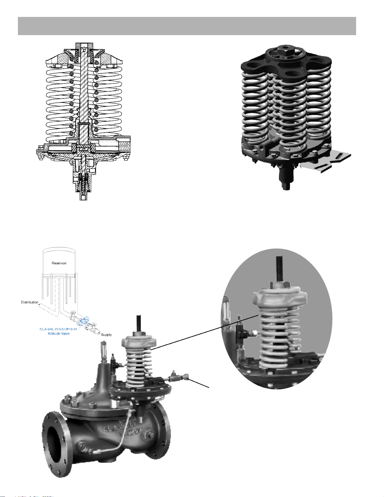
INTRODUCTION
The Cla-Val Model CDS6 Altitude Control is a spring loaded, 3-way,
diaphragm-actuated control that provides high-level shut-off for Cla-Val
Altitude Control Valves. It remotely senses pressure in the reservoir or
tank. There are five altitude ranges available, 5 to 40 feet, 30 to 80 feet,
70 to 120 feet, 110 to 160 feet and 150 to 200 feet. The spring adjusting
nut can be set to stop flow into the reservoir within these ranges.
INSTALLATION
The CDS6 Altitude Pilot Control is normally supplied mounted on a
Cla-Val 210 Series Altitude Valve which should be installed in a horizontal run of pipe with the main valve cover up. Two line block valves are
recommended for valve servicing. If the CDS6 is mounted from the main
valve by a few feet, then it must be installed with adjustment springs up
for ease of adjustment and servicing. Consult factory for recommendations.
After the Cla-Val 210 Series Altitude Valve is installed in the pipeline
close to the reservoir, install the required remote sensing line from the
CDS6 to the reservoir or tank. The sensing line allows the CDS6 to
sense the static pressure head of the reservoir. The sensing line should
not be installed in the flowing line between the valve and the reservoir or
into turbulent flow area. These locations do not reflect the true static
head of the reservoir.
The remote sensing line should be 3/4" or larger copper tubing or
Schedule 40 PVC pipe. Galvanized pipe is not recommended. The sensing line should slope (minimum 2 degrees) upward from the CDS6
toward the reservoir to self -purge air out of the line. The sensing line
should have no high points to entrap air. A shutoff valve at the reservoir
connection is recommended. For above ground reservoirs, the connecting point for the sensing line should be a minimum of 12" to 18" above
reservoir bottom (if filling from bottom) or at fill pipe connection (if filling
from side). Minimum high-level set-point adjustment is approximately
five feet above the remote sensing point of connection.
OPERATION, START-UP AND ADJUSTMENT
When the reservoir pressure (head) is lower than the set point of the
spring on the CDS6 Altitude Control ports "1" and "D" are interconnected. This relieves the main valve cover pressure to atmosphere. Line
pressure then opens the main valve to start filling the reservoir.
Reservoir sensing pressure increases as the liquid level rises in the
reservoir. When the sensing pressure increases to the set point of the
CDS6 control spring, the control shifts interconnecting port "S" and port "1".
This pressurizes the main valve cover chamber and the main valve closes.
By turning the adjusting nut the liquid level shutoff point will be changed.
Turn the adjusting nut clockwise to raise the liquid level shutoff point;
counterclockwise to lower the liquid level shutoff point. Follow the general operation and start-up instructions regarding purging air from the
valve control system.
MAINTENANCE AND INSPECTION
Under normal operating conditions the CDS6 Altitude Control will be
trouble free. There is a visual check possible to determine if there is
damage to the diaphragm in the control. The Lower Cover/Pilot (a) is
vented to atmosphere by means of a small hole in the wall of the casting. If water is discharging out of this opening, the diaphragm should be
inspected for damage.
One other visual check and indication of a problem is continuous discharge from the drain port ("D") at the bottom of the CDS6.
The volume of drained water will vary according to the valve size.
Continuous draining after main valve has fully opened will indicate a
problem. Refer to the service suggestions to check for probable causes
and remedies.
DISASSEMBLY
During preventive maintenance or service to the CDS6 Altitude Control,
all pressure to the control must be shutoff. The CK2 shutoff isolation
valves in the main valve control lines should be closed before starting
disassembly. Main valves 4" and larger have CK2 isolation valves
installed, however main valves smaller than 4" normally do not, therefore
requiring closure of shutoff valves in the main line at the valve inlet and
outlet. The shutoff isolation valve or valve in the sensing line to the reservoir must also be closed.
WARNING: Failure to shutoff and release pressure prior to any
disassembly can result in serious damage to equipment or
injury to personnel.
1. Disconnect tubing at the CDS6 Altitude Control.
2. Remove two mounting caps screws and two lock washers.
3. Remove CDS6 Altitude Control from main valve to work bench or
clean area. Parts must be kept clean.
DISASSEMBLY OF UPPER SPRING SECTION
1. Unscrew adjusting nut (4) from upper stem (5).
NOTE:
Count the number of turns required to remove the nut (4),
record this information for reference when reassembling.
The CDS6 Altitude Control can then be approximately reset for the
same reservoir liquid level shut-off point.
2. Remove the thrust washer (3), swivel retainer (2) and spring
retainers if applicable.
3. Remove Spring(s) (6), bellows (7) and set-screw (8)
4. Remove twelve hex nuts (33), and twelve bolts (32), and set
mounting bracket (29) aside.
Note:
Assembly contains two (of twelve) longer bolts
which are used for the mounting bracket.
ALTITUDE CONTROL
CDS6
29330-06F
29330-07H
29330-08K
29330-09B
29330-10D
CDS6 STOCK
NUMBER
2" SIZE
CDS6 STOCK
NUMBER
2 1/2" SIZE &
LARGER
29330-01E
29330-02G
29330-03J
29330-04A
29330-05D
ALTITUDE
RANGE
(FT H20)
5 - 40
30 - 80
70 - 120
110 - 160
150 - 200
NUMBER
OF
SPRINGS
1
2
3
4
5
0.32
0.64
0.96
1.28
1.60
0.75
1.50
2.20
3.00
3.70
ALTITUDE
CHANGE
PER TURN
PSI
CHANGE
PER TURN
M O D E L
INSTALLATION / OPERATION / MAINTENANCE
2
–
1
Page 21

100
SERVICE SUGGESTIONS
UPPER (SPRING) SECTION
SYMPTOM PROBABLE CAUSE REMEDY
Vent leaks in Diaphragm (14) damaged Replace diaphragm
lower cover (17) Diaphragm nut (12) loose Tighten nut (12)
O-ring (20) damaged Replace O-ring (20)
Leakage past stem O-ring (10) damaged Replace O-ring
stem (5)
Stem (5) move- *Sand or silt in sensing Remove foreign matter
ment restricted chamber above from sensing chamber
or erratic diaphragm
Sensing line clogged Clean line
Sensing line valve closed Open valve fully
Sensing line sagging or Straighten and
bent collecting sediment support sensing line
to reservoir
Sensing line has high Straighten sensing line.
point trapping air in Must slope upward
the line from altitude control
to the reservoir
*NOTE: if this problem occurs, a sand trap should be
installed in the sensing line, or the line moved to a point
on the reservoir where sand or silt cannot enter this line.
SERVICE SUGGESTIONS
LOWER (PILOT VALVE) SECTION
SYMPTOM PROBABLE CAUSE REMEDY
Vent in lower O-ring (20) worn or Replace O-ring (20)
cover (17) leaks damaged. See Upper Spring
Section service suggestion
Flow from supply Clogged strainer screen (25) Remove screen and
port to clean
valve cover port Silt packed in seat (24) Clear area of blockage
restricted and lower stem (21)
Continuous Seat (24) damaged Inspect and replace
drain leak. Main
valve closed Disc in poppet assembly Inspect and replace
(22) damaged poppet assembly
(22)
Foreign object between Remove object
disc and seat (24)
O-ring (20) in poppet Replace O-ring
guide (28) damaged
Continuous Main valve Service main
drain leak. diaphragm worn valve. Replace
Main valve or stem nut loose diaphragm or
open tighten stem nut
5. Thread and securely fasten poppet guide assembly into lower cover
(recommended 200-250 in/lbs.)
6. Turnover lower cover, and assemble as an assembly lower stem
(21) retainer (18) and spring (19) into lower cover, being careful not
damage o-ring (20).
COMPLETING ASSEMBLY
1. Reassembly of twelve nuts (33) and bolts (32) should be torqued to
200-250 in/lbs. Note: assembly contains two longer bolts (item 32)
for the support bracket. These two bolts are to be assembled with
bracket (29) on the two larger support flats located on the lower
cover located 90 degrees from common/supply ports.
3. Install CDS6 Altitude Control assembly on main valve.
4. Replace tube lines and fittings exactly as removed.
5. Remove upper cover (13) from lower assembly, and push stem
assembly through.
6. Remove diaphragm washer nut (12), diaphragm nut washer (16) and
diaphragm (14)
7. Separate upper stem from diaphragm washer by removing stem
retaining pin. (11)
8. Inspect all parts for damage, wear and mineral deposits.
Check O-ring (10) for wear, inspect and remove any deposit in O-ring
area. Also inspect diaphragm for wear or cracks. Clean parts
thoroughly and replace damaged parts as necessary. If, upon
disassembly, sand and silt are found in the CDS6 Altitude Control,
every effort must be made to eliminate this problem. Filters, or
relocating the reservoir sensing line may be required if deposits are
found in the sensing chamber of the control.
REASSEMBLY OF UPPER SPRING ASSEMBLY
1. Reassembly is in general, the reverse of disassembly. NOTE: A light
coating of Dow Corning 33 grease, or equivalent, should be
applied to CDS6 Altitude Control stems (5), before reassembly.
2. When replacing adjusting nut (4) tighten the same number of
turns as referred to in note in paragraph (1) of "Disassembly Of
Upper Spring Section".
DISASSEMBLY OF LOWER PILOT VALVE SECTION
1. Disassemble control per steps 1 through 5 in "Disassembly of upper
section", to work on lower (pilot) cover (17)
2. Remove lower stem (21) spring (19) and retaining ring (18) as an
assembly, inspect stem for damage.
3. Remove Poppet guide (28) and o-ring (27) from lower cover (17).
4. Remove Poppet (22-1) and poppet spring (26) and inspect poppet
and disc for damage.
5. Remove Strainer screen (25)
6. Remove seat (24), Note: be sure not to nick or ding exposed sealing
surface. To prevent binding and damage, use a wood dowel to
evenly tap out the seat from TOP of lower cover (area from which
lower stem was removed).
7. Inspect all parts for damage, wear and mineral deposits. If there
has been discharge from vent hole, remove o-ring (20) from lower
cover (17) and poppet guide (28). Inspect o-rings for wear or
damage and o-ring groove for material build-up. Clean and/or
replace as necessary. Inspect seat (24) and disc poppet assembly
(22) for wear or damage. If poppet and/or disc are damaged they
must be replaced as an assembly (item 22). Otherwise clean and
polish surfaces of moving parts with 600 wet/dry sandpaper. Also
clean strainer screen (25) of any deposits
REASSEMBLY OF LOWER PILOT VALVE SECTION
1. Reassembly is in general, the reversal of disassembly. Note: A light
coating of Dow Corning 33 grease, or equivalent should be applied
to all o-rings and moving part surfaces (20,21,22-1 23 and 27).
2. Lay lower cover (17) on its top (do not damage serrated surface),
insert the seat (24) with o-ring (23) in lower (pilot) cover with finger.
Use a wood dowel to push the seat in fully with hand pressure
ONLY. Note: damage to the seat can compromise the sealing
ability of the control, and careful efforts must be applied on
reassembly of this component.
3. Insert strainer (25).
4. Install poppet guide, o-ring, spring and poppet assembly.
(See Note #1 for greasing)
N-CDS6 (R-5/05)
Page 22

101
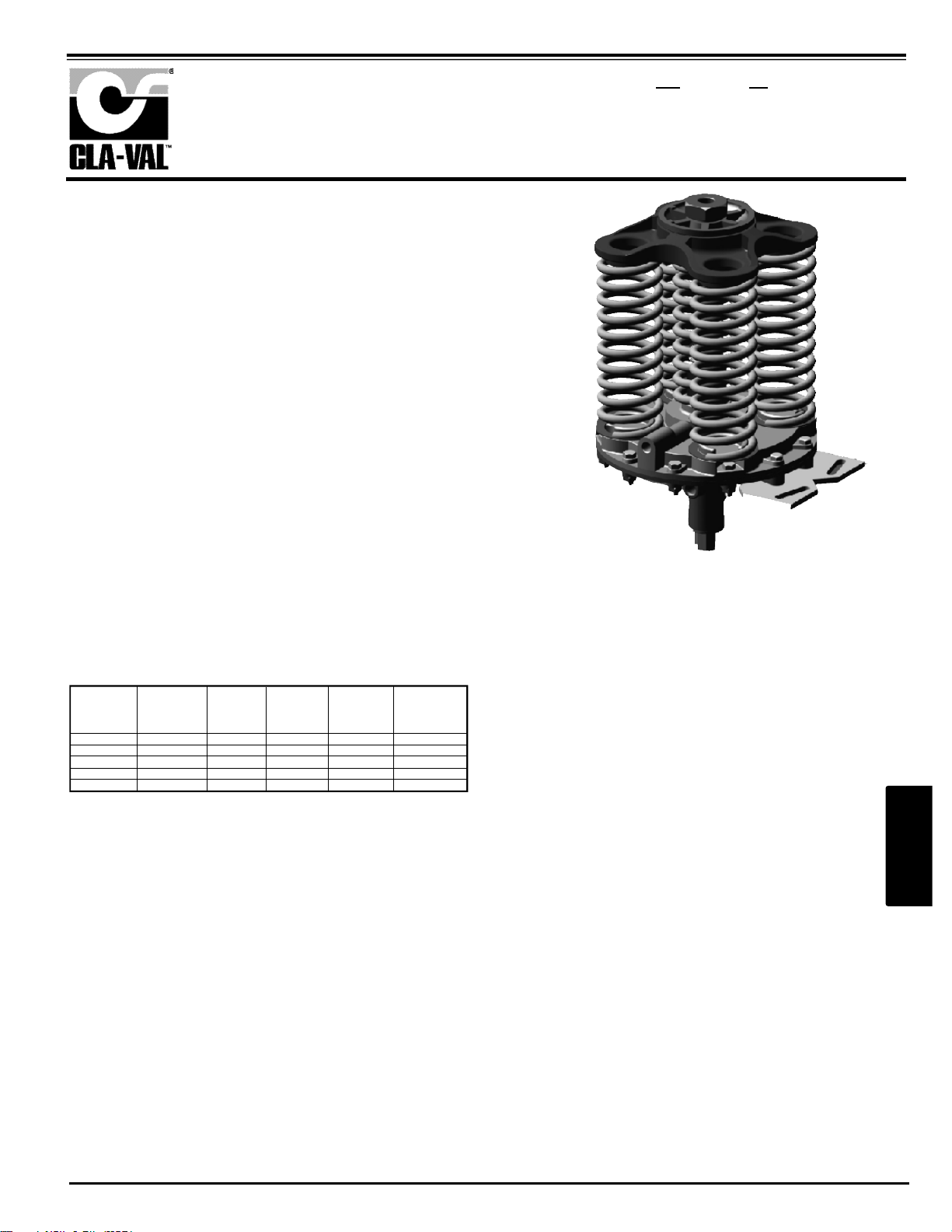
CDS6 Improvements
Recently, our Engineering Department redesigned a few internal parts of the CDS6 Pilot Control
used on 210 Series Altitude Valves. These new parts improve its sensitivity at high differential pressures and allow it to work with inlet supply pressures up to 300 psi (previous maximum recommended pressure was 150 psi). The new control is identified as CDS6A and new part numbers are
assigned to distinguish it from the original CDS6. Adjustment ranges remain the same.
New parts inside the CDS6A are a) stem seals, b) disc and poppet assembly, c) lower stem, d)
lower cover, e) poppet guide, and f) poppet spring. The CDS6A uses new low-friction seals on the
lower stem and the disc and poppet assembly. Also, the new stem and poppet have a special lowfriction nickel-Teflon coating and are dimensionally interchangeable with CDS6 parts. The new
lower cover and poppet guide have larger internal dimensions for the new seals and are not interchangeable with CDS6 parts. Also, the poppet spring has a heavier load and is not interchangeable. All other parts remain the same.
All bills of material for top assemblies using the CDS6 have been changed to the new control. It will
take some time for us to change assembly drawings and deplete existing parts before we begin
using the CDS6A. We plan to finalize the change during first quarter of 2003.
A new CDS6A repair kit is p/n 20349401C and will not work with existing CDS6 controls. The repair
kit will include instructions and tools to install new stem seals. When servicing existing CDS6 controls the current repair kit p/n 20119301A should be used.
A modification kit consisting of all new parts and instructions is p/n 20354801G. Field modification is
recommended only for installations where it is determined to be necessary.
Range (ft) size p/n size p/n
5 - 40 2 _" & larger 20354701K 2" & smaller 20354706E
30 - 80 2 _" & larger 20354702J 2" & smaller 20354707D
70 - 120 2 _" & larger 20354703H 2" & smaller 20354708C
110 - 160 2 _" & larger 20354704G 2" & smaller 20354709B
150 - 200 2 _" & larger 20354705F 2" & smaller 20354710J
Technical Bulletin
2
–
1
April 2 2003
Page 23
102
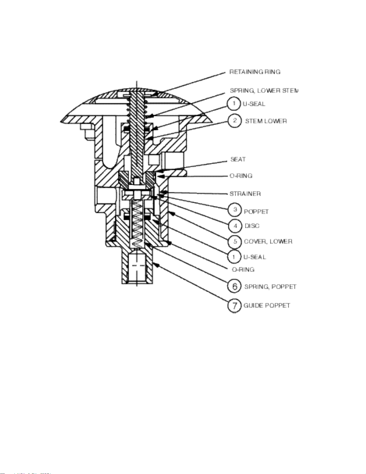
NEW CDS6A PARTS ARE ABOVE NUMBERED ITEMS.
A) All other parts are the same as current CDS6 parts.
B) Two new low-friction U-Seals, Item 1, will not fit into O-ring grooves of CDS6 lower cover and
poppet guide. The machined groove dimensions are different between the O-ring version and the
new U-seal version parts. New Lower Cover, Item 5, and Poppet Guide, Item 7, have proper
dimensions for U-Seal.
C) Lower Stem, Item 2, and Poppet, Item 3, are dimensionally interchangeable with CDS6 parts
that are now obsolete. These new parts have a special low-friction coating which may enhance
CDS6 performance.
D) Poppet Spring, Item 6, has a heavier load rating and is not interchangeable with CDS6 poppet
spring. Sensitivity will be greater than a 12" differential, if used in CDS6 controls.
Page 24

103
CF1-C1
CF1-C1
CF1-C1
CF1-C1
CF1-C1 Float Control
is a float-actuated multiport pilot control which provides non-modulating, two-position, on-off operation. It is used primarily to operate remotely located Cla-Val valves requiring three-way or four-way
pilot valve operation for level control. Control can be remotely located.
CF1-C1
124-01/624-01
Schematic Symbol
2
–
1
Page 25

104
CF1 Series Float Controls
CF1 Series
INSTALLATION / OPERATION / MAINTENANCE
Initial Adjustment CF1 Series Float Controls
Check installation to be sure that liquid surface is not subject to wind or currents, if so, a stilling well should be
installed around the float and rod assembly. A short section of 8" pipe (PVC) mounted vertically in the tank
around the float and rod is suggested.
1. See parts sheet (other side of this sheet) for proper assembly of the float rod, float, and stop collars and for
threading into the Link Assembly of the CF1-C1.
2. Balance the Float Rod Assembly. This compensates for the buoyancy of the float rod in the water.
Temporarily remove float by removing float rod and float from the link assembly. Remove float from float rod,
reinstall rod assembly (leave stop collars on float rod) back into link assembly.
Adjust counterweight on rod to balance the weight of the float rod assembly less the float. Loosen setscrew on
counterweight and move weight in or out round rod remains horizontal without shifting. Tighten setscrew.
Check by pushing up or down on float rod assembly and seeing that entire assembly returns to balanced position. Replace float between the stop collars. The counterweight size changes as float rod is lengthened.
Consult factory for more information.
3. Set Float High Level Shut-Off. Move float rod to "up" position. Adjust the upper stop collar on the float rod
assembly approximately three inches above the desire high water level. Move float rod to "down" position.
Adjust the lower stop collar on the float rod assembly approximately three inches below the desired low water
level. Tighten collar set screws.
4. If the closing level is too high, allowing tank to overflow, then the top stop collar on the float rod should be
lowered. If the opening level is too low, then the bottom stop collar should be raised.
If the counterweight has been properly adjusted the float will move freely on the float rod, without causing the
pilot arm to raise or lower, until the float actually contacts one of the stop collars.
5. For reference: with a new control and supply pressure less than 40 psi the maximum level differential available will be: 18 to 20 inches with PVC float and rod assembly and 48 to 50 inches with Stainless Steel or Brass
float and rod assembly.
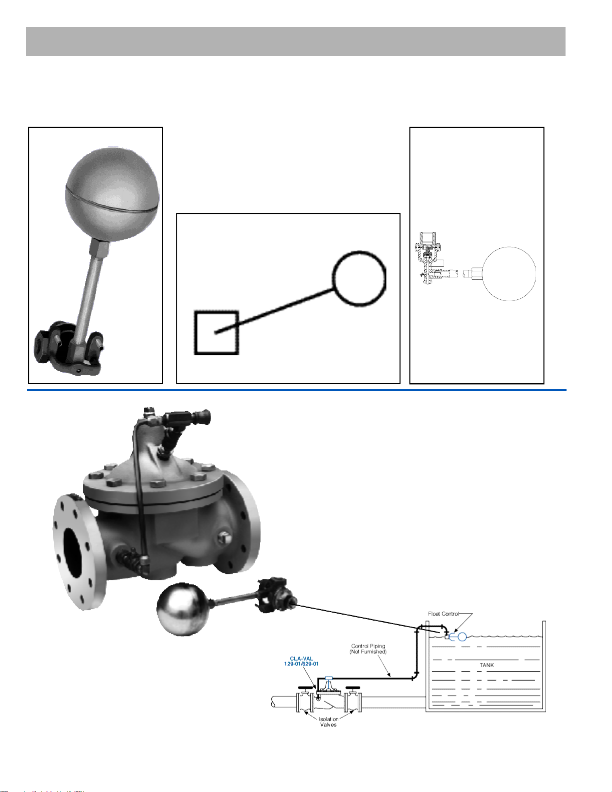
Installation Data
The float control is mounted above the
high water level in the tank. The valve is
installed in the line leading to the tank
and is connected to the float control
pilot by tubing. (Min. 3/8" tubing)
When line pressure is used to operate
the valve, tubing connections are made
from the float control pilot to the valve
cover, and also to the inlet side of the
valve. An X43 “Y” Strainer or X46 Flow
Clean Strainer must be installed in the
inlet side of the valve. The control may
be installed at any elevation above the
valve, providing that the flowing line
pressure in psi is equal to, or greater
than, the vertical distance in feet
between the valve and the float control.
An independent source of air or water
may be used to operate the valve. The
pressure from this independent source
must constantly be equal to or greater
than pressure at the valve inlet. The
independent source is connected to the
float control pilot in place of the supply
line connected to the inlet side of the
valve. If the Model 100-01 under the
control of the CF1-C1 is 8" or larger,
auxiliary Hytrols may be required.
Consult factory for details.
N O T E :
A stilling well (Min. 8" I.D.) must be provided around the float if the liquid su r f a c e
is subject to turbulence, ripples or wind.
Note: We recommend protecting Float Control tubing and valve from freezing temperatures.
Page 26
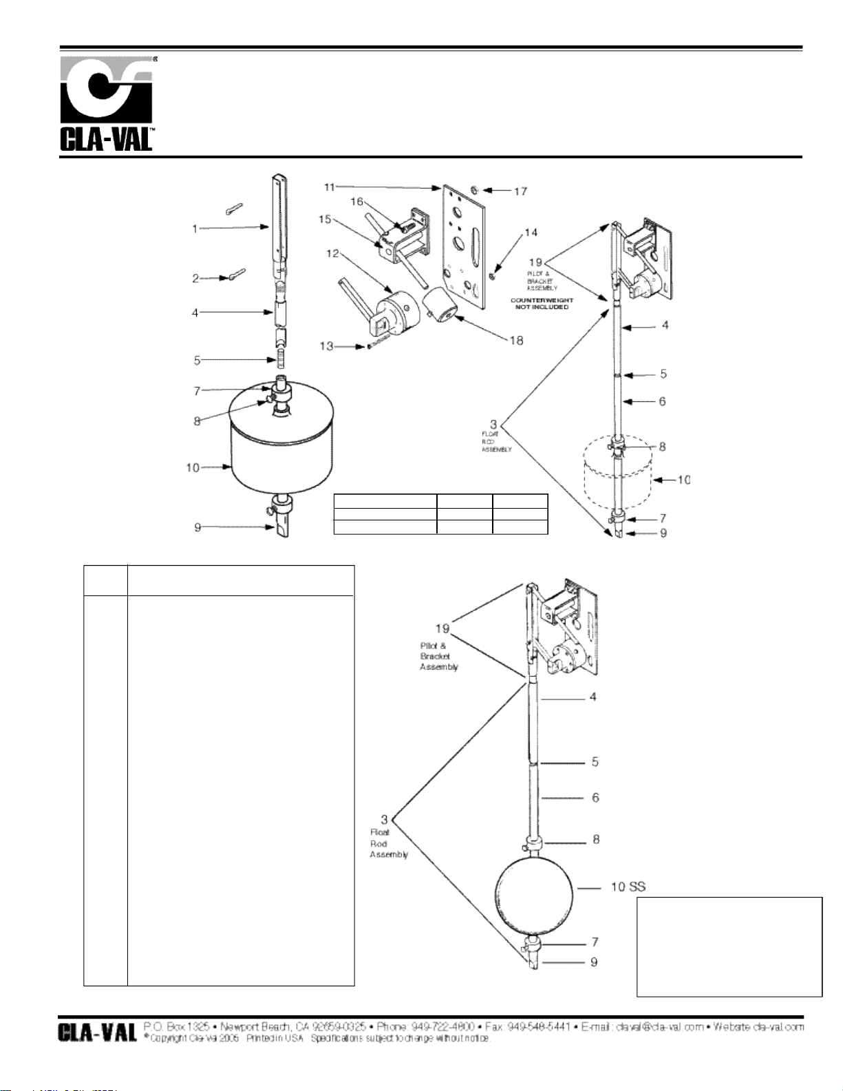
105
When ordering parts,
please specify:
• All nameplate data
• Description
• Item Number
ITEM DESCRIPTION
1 Link Assembly
2 Cotter Pins (2 req'd)
3 Float Rod Assembly (2 ft. )
FLOAT ROD ASSY. BREAKDOWN ITEMS 4 - 9
4 Upper Float Rod (1 ft.)
Upper Float Rod (2 ft.)
5 Stud (Req. for connecting upper and lower rods
and one for each extension rod)
6 Extension Float Rod (1 ft.)
Extension Float Rod (2 ft.)
7 Stop Collar (2 req'd)
8 Set Screw (1 ea. stop collar)
9 Lower Float Rod (1 ft.)
Lower Float Rod (2 ft.)
10 Float Ball (Standard Plastic)
10 SS Float Ball (Optional Stainless Steel)
11 Base and Mounting Plate
12 Pilot Valve Assembly CF1-Cl
13 Machine Screw 6/32 x 1 1/2" (6 req'd.)
14 Hex Nut 6/32 (6 req)
15 Counter Balance Bracket Assy.
16 Machine Screw 10/32 x 9/16" (4 req'd.)
17 Hex Nut 10/32 (4 req'd.)
18 Counterweight (varies with rod
length, includes set screw)
19 Pilot & Bracket Assembly CF1-Cl
COUNTERWEIGHT NOT INCLUDED
OPERATION
FLOAT POSITION PORT 1 PORT 2
Up Pressure Drain
Down Drain Pressure
Float Control
CF1-C1
Optional Stainless Steel Float
N- CF1-C1 (R-8/05)
PARTS LIST
Page 27

106
CFC2 Float Control
is a float-actuated multiport pilot control which provides non-modulating, two-position, on-off operation.
It is used primarily to operate remotely located Cla-Val Main Valves requiring three-way or four-way pilot
valve operation.
CFC2
CFC2
CFC2
CFC2
Schematic Symbol
Pilot Controls
Section 2 - 1
Page 28

107
CFC2
Float Control For Closed Tanks
Specifications
• Accurate Liquid Level Control
• Fully Hydraulic Operation
• Simple Design, Easy Maintenance
• No Lubrication Necessary
• No Gears, No Mechanical Linkage Between
Valve and Control
The Cla-Val Model CFC2 Float Control is a float-actuated multiport
pilot control which provides non-modulating, two-position, on-off
operation. It is used primarily to operate remotely located Cla-Va l
Valves requiring three-way or four-way pilot valve operation.
Designed for use in closed tanks, this control operates on a minimum level change of approximately 1". Maximum level change of
5
1 / 2
" is needed for full capacity.
Note: We recommend protecting the control tubing and valve from
freezing temperatures.
Dimensions
(In Inches)
Control Piping
C o n n e c t i o n s
1 / 8
" NPT
R e s e r v o i r
C o n n e c t i o n s 1" NPT
Pressure Rating 0-300 psi
Te m p e r a t u r e
R a t i n g Water: to 180°F.
M a t e r i a l s In contact with operating fluid:
Brass, stainless steel, monel, with
B u n a - N®S e a l s
Float chamber:
Cast Iron
Pilot valve housing:
B r o n z e
Materials in contact with operating fluid:
Brass, Stainless Steel, Monel with
B u n a - N®S e a l s
Float ball:
Stainless Steel
Float arm:
B r a s s
Other material available:
Cast steel or aluminum chamber and
pilot valve housing. A l l
stainless steel
Level Differential Approximately 1" minimum required to
change pilot valve operation. 5 5 / 1 6"
required to develop full capacity.
Operating Fluids Clean liquids or gases compatible with
specified materials.
Shipping We i g h t 12 Lbs.
MODEL
2
–
1
Page 29
108
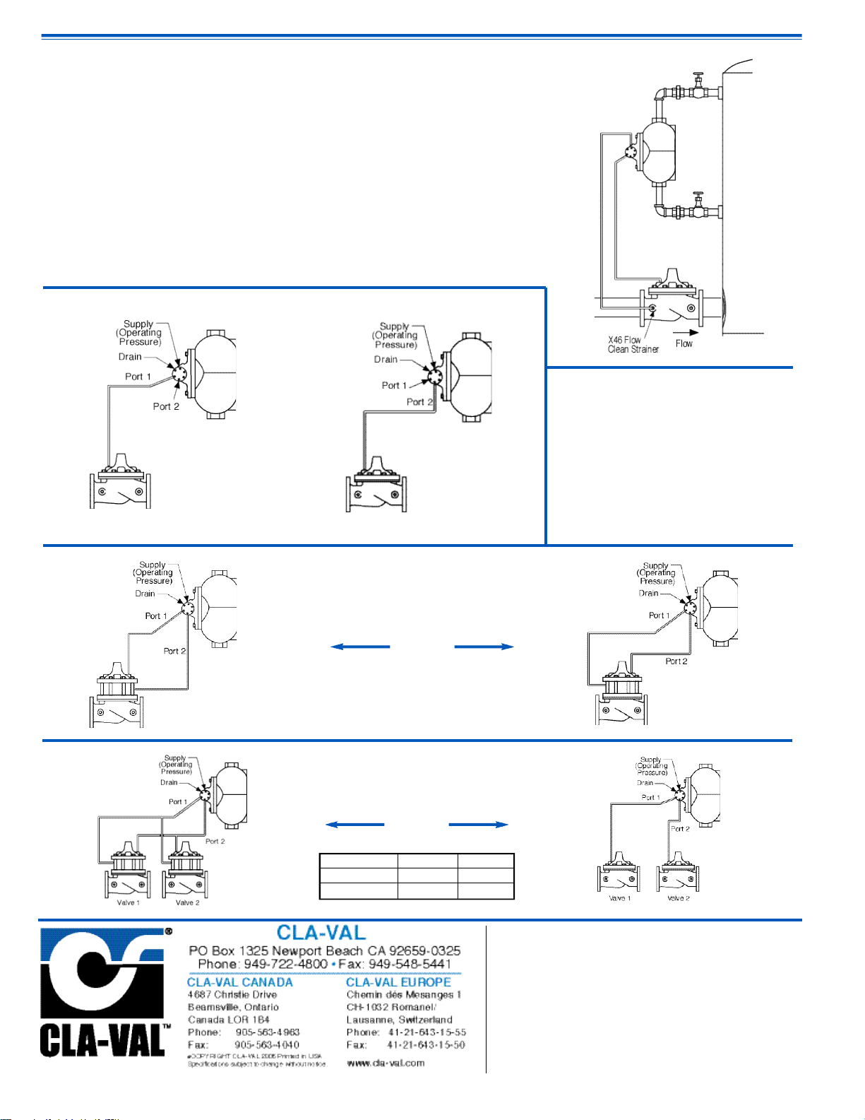
Installation Data
For Controlling Hytrol Valve
The float control is mounted at the high water
level in the tank. The remote Cla-Val valve is
installed in the line leading to the tank and is
connected to the float control pilot by tubing.
(Min. 3⁄8" for valves 6" and smaller,3⁄4" or larger
for valves 8" or larger.)
When line pressure is used to operate the valve,
tubing connections are made from the float control pilot to the valve cover, and also to the inlet
side of the valve. An X46 Flow Clean Strainer
must be installed in the inlet side of the valve.
The control may be installed at any elevation
above the valve, providing that the flowing line
pressure in psi is equal to, or greater than, the
vertical distance in feet between the valve and
the float control.
An independent source of air or water may be
used to operate the valve. The pressure from
this independent source must constantly be
equal to or greater than pressure at the valve
inlet. The independent source is connected to
the float control pilot in place of the supply line
connected to the inlet side of the valve. If the
Model 100-01 under the control of the CFC2 is
8" or larger, auxiliary Hytrols may be required.
Consult factory for details.
Note: We recommend protecting the control tubing and valve from freezing temperatures.
For Controlling
Powertrol Valves
Float Up Float Up
Closes Valve Opens Valve
When Ordering, Please
S p e c i f y
1 . Catalog No. CFC2-C1
2 . Size and type of Valve to be
c o n t r o l l e d .
3 . Materials if different from standard
4 . Specify gravity of fluid if other than
w a t e r .
Float Up Closes Va l v e Float Down Closes Va l v e
Float Position Valve 1 Valve 2
UP CLOSED OPEN
DOWN OPEN CLOSED
Operation
For Controlling
Two Valves Simultaneously
E-CFC2 (R-5/05)
Represented By:
Page 30
109
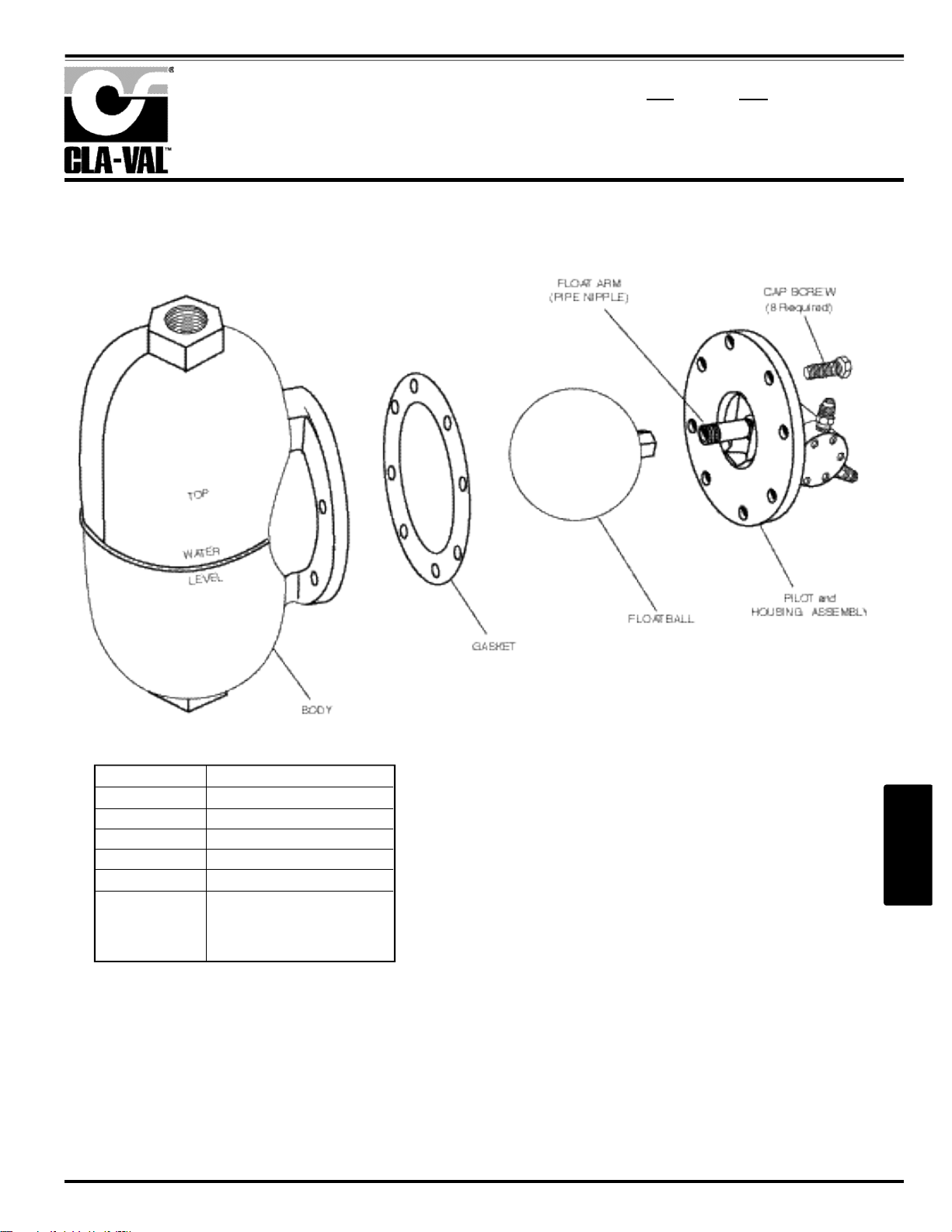
PARTS LIST
C F C 2
Float Chamber Control
M O D E L
Description
Float Ball
*Gasket
Cap Screws
3/8-16 x 7/8
Body
Float Arm
Pipe Nipple
1/4"x1/2" npr
Material
Stainless Steel
Neoprene
Steel Cad.
Plated
Iron
Bronze/Stainless Steel
2
–
1
Page 31
110
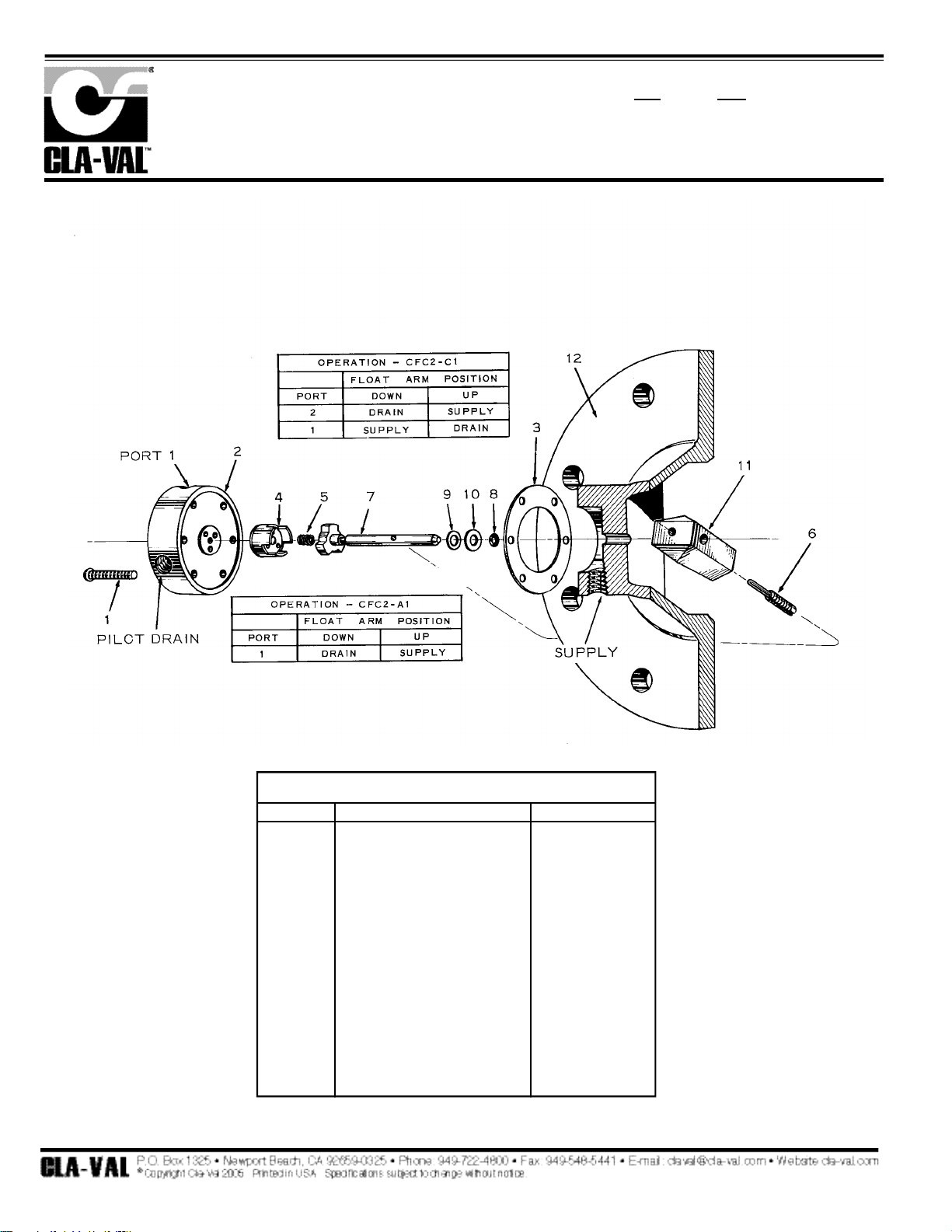
PL-CFC2 (R-5/05)
PARTS LIST
C F C 2
Pilot & Housing Assembly For Float Chamber Control
M o d e l
PILOT & HOUSING ASSEMBLY (BRONZE W/STAINLESS STEEL)
ITEM
1
*2
*3
*4
*5
6
7
*8
9
10
11
12
DESCRIPTION
Machine Screw, Rd. Hd.,
6/32 x 1", 6 Required
Distributor for C426-1
Distributor for C-2035
Distributor for C-2149-1
Gasket
Disc Assembly
Spring
Pin, Lock
Stem Assembly
“O" Ring
Washer
Washer, Thrust
Arm, Float
Housing
MATERIAL
Brass
S.S.
S.S.
S.S.
Buna-N
®
S.S.
S.S.
S.S.
S.S.
Brass - S.S.
Buna-N
®
Brass
Brass
Brass
Bronze
* Repair Kit Parts
OBSOLETE REFERENCE ONLY
Page 32

111
CFC2-A1-3 Float Chamber Control CONVERSION
(also CFC2-A2-3 Float Chamber Control)
This control is obsolete and is replaced by the CFC2-C1 Float Chamber Control. The diff e r e n c e s
between these controls are few. Refer to E-CFC2-C1 data sheet.
A. The pilot housing assembly is now installed on the float chamber so that the distributor is on
the right of the vertical centerline of the control. The word "top" is cast into the pilot housing
flange. There is an "O" ring seal between the pilot housing and the float chamber instead of earlier flat gasket.
B. The disc and distributor are the same as those of the CF1-C1 Float Pilot Control.
C. The CFC2-C1 has 4 ports. "Supply" is found on the housing. "Port 1", "Port 2" and "Drain"
are located and marked on the Distributor. Port 2 is for special applications and will have a pipe
plug in it. "Supply" port on the distributor is not used and has an Allen socket plug in it.
1. When service is required for the CFC2-A1-3 (or CFC2-A2-3) Control, then conversion to
CFC2-C1 is recommended.
2. For converting to the current design control, use Repair Parts Kit for the CFC2-C1 control.
Order Kit P/N 2674701E (in standard materials). Also, use this kit for maintenance or servicing
the CFC2-C1 control after conversion. This kit includes new disc, distributor, ‘O’ rings, gasket,
spring and screws. Spare Parts Kit P/N 9696630E had only 'O' ring, gasket and spring and is
obsolete and no longer available.
3. The new CFC2-C1 pilot housing flange seal is redesigned from a flat gasket to a groove for an
'O' ring seal with the chamber. This 'O' ring is in repair parts kit. The flat gasket is still available,
order part number C3580C, it is also in the kit.
4. Be sure to install parts so that the pilot housing is mounted with the distributor located to the
right of the vertical centerline of the control. Pilot tubing and connections will have to be relocated when converting.
5. The repair kit comes with a 1/8" hex-head pipe plug to be installed in pilot port 2. This will
give the ON-OFF operation from Port 1 the same as the previous CFC2-A1. By removing this
plug from Port 2 and installing in Port 1, the operation of the control becomes that of the previous CFC2-A2. By not installing the plug, the operation becomes that of the previous CFC2-C1.
Also, there is a 1/8" Allen socket pipe plug to be installed in the "S" supply port on the distributor.
Once installed THIS PLUG SHOULD NOT BE REMOVED. Supply pressure is to be connected
to the supply port on the pilot housing of the control.
Technical Bulletin
2
–
1
Page 33
112
CFM2 Modulating Float Control
is a precision-lapped, rotary-disc, plate-type valve directly operated by the movement of a float ball. It
is designed to control a Cla-Val Hytrol Main valve to maintain level in liquid storage tanks.
Pilot Identification
CFM2
CFM2
CFM2
129-01/629-01
Schematic Symbol
Page 34

113
INSPECTION
Inspect all threads for damage or evidence of cross-threading.
Check float ball for crushing and punctures. Check spring for
visible distortion, cracks and breaks. Inspect distributor and
valve disc for clogged holes.
REPAIR AND REPLACEMENT
Replace O-Ring packing and distributor gasket each time valve
is overhauled. Replace float ball if at all crushed or punctured.
Minor nicks and scratches may be polished out using a fine
grade of emery or crocus cloth.
Replace all parts which are defective, and any which create the
slightest doubt that they may not afford completely satisfactory
operation. Use inspections outlined above as a guide.
Lapping of disc and distributor in the field is not recommended
because of the difficulties involved in getting perfectly flat surfaces. If repair is need on either of these parts, replace the control with a spare, and return defective unit to Cla-Val for repair.
REASSEMBLY
Replace valve disc in the position previously marked to obtain
proper flow pattern through holes.
TEST PROCEDURE
Attach a source of pressure (air or water) to "inlet" port and
check for tight sealing when float is "up".
CFM2
Modulating Float Control
DESCRIPTION
The Type CFM2 Float Control is a precision-lapped, rotary-disc, platetype valve directly operated by the movement of a float ball. It is
designed to control a Cla-Val Hytrol Main valve to maintain level in liquid storage tanks.
OPERATION
Any change in the level of the storage tank is detected instantly by the
ball of the Float Control mounted inside the tank. The float ball is
attached to a lever arm which transmits a turning motion to the valve
disc as the float rises and falls.
In the closed position, the holes in the valve disc do not meet with the
holes in the distributor, and completely prevent all flow through the
Float Control. In the half-open or modulating position, the holes in the
valve disc only partially coincide with the holes in the distributor, permitting a restricted flow through the Float Control. In the open position,
the holes in the valve disc line up completely with the holes in the distributor permitting full flow through the Float Control.
INSTALLATION
The Float Control can be installed to be either fully closed or fully open
when float is in the "up" position. Normal applications require the
Control to be installed so that it is in the closed position when the float
ball is raised.
DISASSEMBLY
Follow the sequence of item numbers assigned to the parts in the
cross-sectional illustration for recommended order of disassembly.
Mark parts so they may be reassembled in their proper position.
CLEANING
Wash all parts with cleaning solvent, Federal specification P-S-661, or
approved equivalent. Dry with compressed air, or a clean, lint-free
cloth. Protect parts from damage and dust until reassembled.
ITEM DESCRIPTION QTY PART NO.
1 FLOAT 1
2 ARM EXTENSION NIPPLE 1
3 LOCK PIN 1
4 SCREW -RD HD MACHINE 6
5 DISTRIBUTOR 1
6 GASKET 1
DISC ASSEMBLY 1
7 DISC 1
8 SKIRT 1
9 SPRING 1
STEM ASSEMBLY 1
10 DRIVER 1
11 STEM 1
12 THRUST WASHER 1
13 O-RING PACKING 1
14 FLOAT ARM 1
15 HOUSING 1
M O D E L
INSTALLATION / OPERATION / MAINTENANCE
N-CFM2 (R-5/05)
2
–
1
Page 35

114
DESCRIPTION
W/COPPER FLOAT BALL,
BRASS ARM AND BRASS
ARM EXTENSION
W/S.S. FLOAT BALL, ARM
& ARM EXTENSION
SIZE
1/2"
1/2"
CFM2
Modulating Float Control
†
Permanently Joined Assembly
PL-CFM2 (R-5/05)
PARTS LIST
Item
1
2
3
4
5*
6*
Description
Float Ball
Arm Extension
1/4" Dia. X 5" Long
Lock Pin
Machine Screw, Fil. Hd.
6.32 x 5/8 (6 Req’d)
Distributor
Gasket
Item
7 & 8*
9*
10 & 11
12
13*
14
15
Description
†
Disc Assembly
(7-Disc / 8-Skirt)
Spring
†
Stem Assembly
(10-Driver)
(11-Stem)
Thrust Washer
“0" Ring 3855-B
Float Arm
Housing
Page 36
115
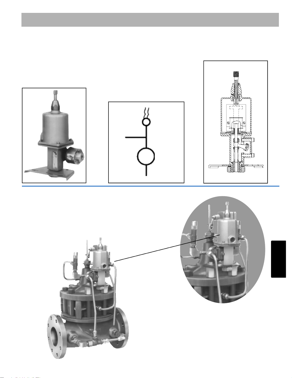
CSM-11 Solenoid Control with Manual Operator
is a direct-acting solenoid valve for use in four-way, three-way, and interceptor service. It is a continuous duty type which assures positive and dependable operation over the entire pressure range.
Cla-Val can refurbish into new condition when needed.
Pilot Identification
CSM11
CSM11
CSM11
CSM-11
60-11/660-11
Schematic Symbol
2
–
1
Page 37
116
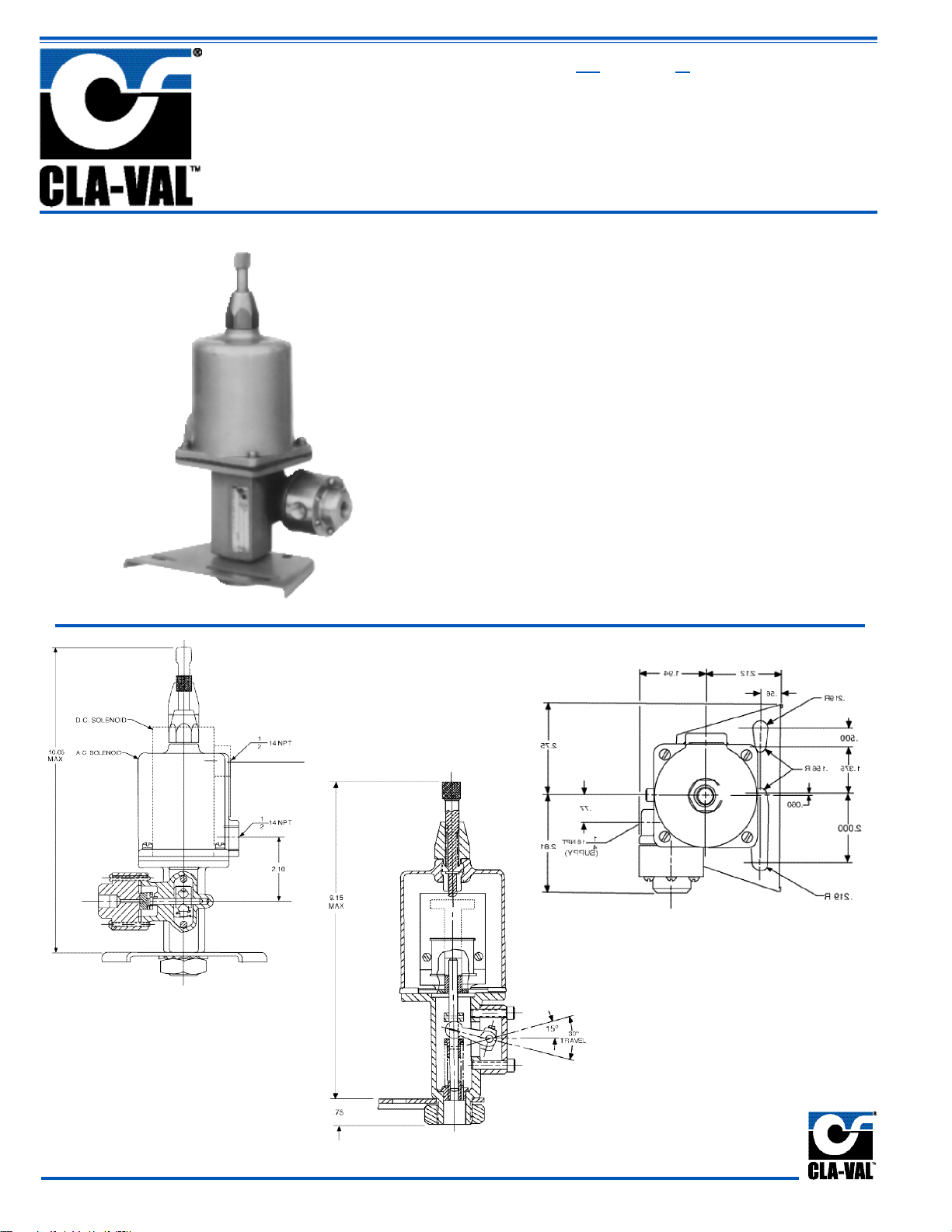
Solenoid Control with Manual Operator
CSM-11
• Positive Operation Through Full Pressure Range
• Both Manual and Electrical Operation
• Coil is Protected Against Foreign Matter by Sealtight Gasket Cover
• Moving Parts of Solenoid are Cushioned
• Modular Pilot Assembly Provides for Easy
Replacement and Minimum Down Time
The Cla-Val CSM-11 is a direct-acting solenoid valve for use in
four-way, three-way, and interceptor service. It is a continuous
duty type which assures positive and dependable operation
over the entire pressure range. The valve is positioned to direct
pressure into pre-determined flow patterns by means of the
solenoid and connecting linkage. The valve is a rotary disc,
plate type, lapped for drip tight operation. The control is
designed for manual as well as electric operation.
MODEL
Page 38

117
2
–
1
Service Specifications
Solenoid Enclosure General Purpose, NEMA Type 3
Size (Fluid Connection) 1/4" NPT Supply Port and 1/8" NPT
Connector Ports
Operating Media Water, air, gas (compatible with
materials)
Coil Insulation Class A (molded)
Operating Pressure 300 psi maximum working pressure
Temperature Water to 150° maximum
Materials Bronze, Stainless Steel and Monel*
(Fluid Contacts) Aluminum Body—Stainless Steel
Trim
*Other materials available - consult factory.
Operation
The Cla-Val Co. CSM-11 Solenoid Control meets varied service
requirements depending upon the flow pattern used. Catalog
number SUFFIXES are used to designate specific flow patterns.
Other variations are available on special order.
When Ordering, Please Specify
1. Catalog No. CSM-11
2. Include suffix of desired type of service
Four-way or Interceptor
3. Voltage and Hertz
Purchase Specifications
The control shall include a continuous duty direct acting solenoid,
and shall be designed for both manual and electrical operation.
The valve shall be integral, of a rotary disc, plate type, and shall
be actuated by the solenoid through a linkage. The control shall
be similar in all respects to the CSM-11 Solenoid Control as manufactured by Cla-Val., Newport Beach, California.
Power Consumption
E-CSM-11 (R-8/05)
Represented By:
Volts Amperes Volts Amperes Coil
(DC) Holding Pull In (AC 60 Hz) Holding Inrush
Resistance
24 .603 24 24 2.88 25.4 0.5
28 .629 15.6 120 .575 5.1 14.1
32 .500 18.6 208 .330 2.93 40
48 .293 10.8 240 .288 2.54 56
115 .122 4.42 440 .156 1.38 174
125 .119 4.44 480 .143 1.27 233
250 .072 2.45
Volts Amperes Coil
(AC 50 Hz) Holding Inrush
Resistance
110 .48 4.6 15.7
220 .24 2.3 66
240 .22 2.1 88
(ohms)
(ohms)
Page 39
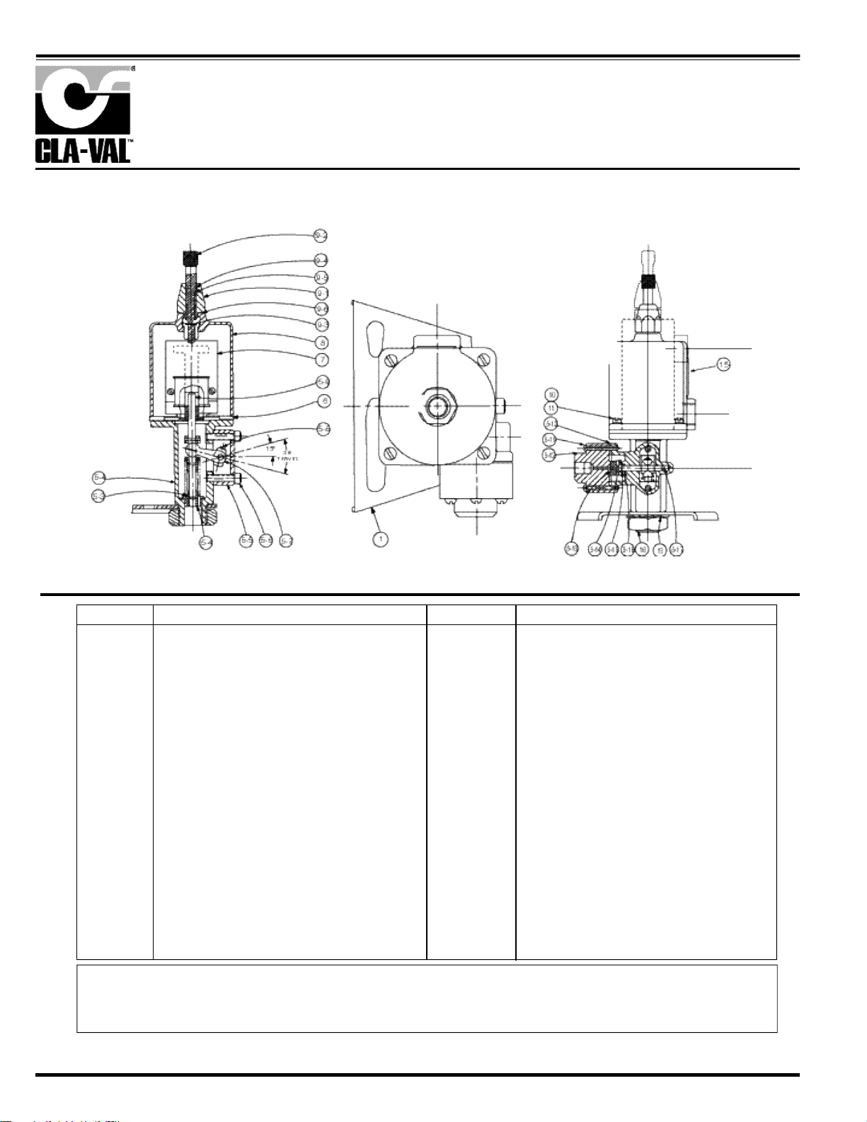
118
When ordering parts, please specify:
• All Nameplate Data • Description • Recommended Spare Parts
• Item Number • Material
ITEM DESCRIPTION
1 Mounting Bracket
5 Mechanical Parts Assy.
5-2 Housing
5-3 Spring
5-4 Guide
5-5 Side Housing
5-6 Cap Screw 1/4'
5-7 Lever Arm
5-8 Lever Screw
5-9 Stem assy. (Solenoid)
5-10 Distributor Gasket
5-11 Machine Screw, RDH
(6/32 x 1 1/4 - 6 req'd.)
5-12 Distributor (CSM11-A2-2)
5-13 Disc Assy.
5-14 Spring (Disc Assy.)
5-15 Thrust Washer
5-16 "O"- Ring
5-17 Stem Assy. (Pilot)
6 Spacer Gasket (A.C. only)
ITEM DESCRIPTION
7 Solenoid Assy.
(See table other side)
8 Cover (A.C. only)
9 Manual operator assy
9-1 Housing, Manual Operator
9-2 Plunger
9-3 Pin, groove-3/8"
9-4 "O"- Ring
9-5 Spring, Manual Operator
9-6 Gasket, Manual Operator
10 Machine Screw Fil. Hd.
(A.C. Only 10/32 x 5/8-4 req'd.)
(4 req'd.)
11 Lockwasher
12 Machine Screw Fil. Hd.
(D.C. Only) 10/32 x 7/16 (4 required)
13 Lockwasher
14 Coil only: (See table other side)
15 Nameplate
16 Hex Nut, Jam 1-14 UNS
Solenoid Control
CSM-11
PARTS LIST
Page 40

119
CV-Speed control
is used to control opening or closing speed. The CV allows restricted flow in one direction and restricted flow
in the opposite direction. To be cleaned up sample only.
End Connection 3/8 male NPT and 3/8" Female NPT
Bronze or Stainless Steel body/ stainless steel trim.
Maximum working Pressure 400 PSI
Components Identification
CV
CV
CV
Section 2 - 1
Schematic Symbol
2
–
1
Page 41

120
INSTALLATION / OPERATION / MAINTENANCE
Flow Control
CV
MODEL
N-CV (R-5/05)
DESCRIPTION
The Cla-Val Model CV Flow Control is a simply-designed,
spring-loaded check valve. Rate of flow is full flow in one direction and restricted in other direction. Flow is adjustable in the
restricted direction. It is intended for use in conjunction with a
pilot control system on a Cla-Val Automatic Control Valve.
OPERATION
The CV Flow Control permits full flow from port A to B, and
restricted flow in the reverse direction. Flow from port A to B
lifts the disc from seat, permitting full flow. Flow in the reverse
direction seats the disc, causing fluid to pass through the clearance between the stem and the disc. This clearance can be
increased, thereby increasing the restricted flow, by screwing
the stem out, or counter-clockwise. Turning the stem in, or
clockwise reduces the clearance between the stem and the
disc, thereby reducing the restricted flow.’
INSTALLATION
Install the CV Flow Control as shown in the valve schematic
All connections must be tight to prevent leakage.
DISASSEMBLY
Follow the sequence of the item numbers assigned to the
parts in the cross sectional illustration for recommended
order of disassembly.
Use a scriber, or similar sharp-pointed tool to remove O-ring
from the stem.
INSPECTION
Inspect all threads for damage or evidence of crossthreading. Check mating surface of seat and valve disc for
excessive scoring or embedded foreign particles. Check
spring for visible distortion, cracks and breaks. Inspect all
parts for damage, corrosion and cleanliness.
CLEANING
After disassembly and inspection, cleaning of the parts can
begin. Water service usually will produce mineral or lime
deposits on metal parts in contact with water. These
deposits can be cleaned by dipping the parts in a 5-percent
muramic acid solution just long enough for deposits to dissolve. This will remove most of the common types of
deposits. Caution: use extreme care when handling
acid. If the deposit is not removed by acid, then a fine grit
(400) wet or dry sandpaper can be used with water. Rinse
parts in water before handling. An appropriate solvent can
clean parts used in fueling service. Dry with compressed air
or a clean, lint-free cloth. Protect from damage and dust
until reassembled.
REPAIR AND REPLACEMENT
Minor nicks and scratches may be polished out using a fine
grade of emery or crocus cloth; replace parts if scratches
cannot be removed.
Replace O-ring packing and gasket each time CV Flow
Control is overhauled.
Replace all parts which are defective. Replace any parts
which create the slightest doubt that they will not afford completely satisfactory operation. Use Inspection steps as a
guide.
REASSEMBLY
Reassembly is the reverse of disassembly; no special tools
are required.
TEST PROCEDURE
No testing of the flow Control is required prior to reassembly
to the pilot control system on Cla-Val Main Valve.
Page 42
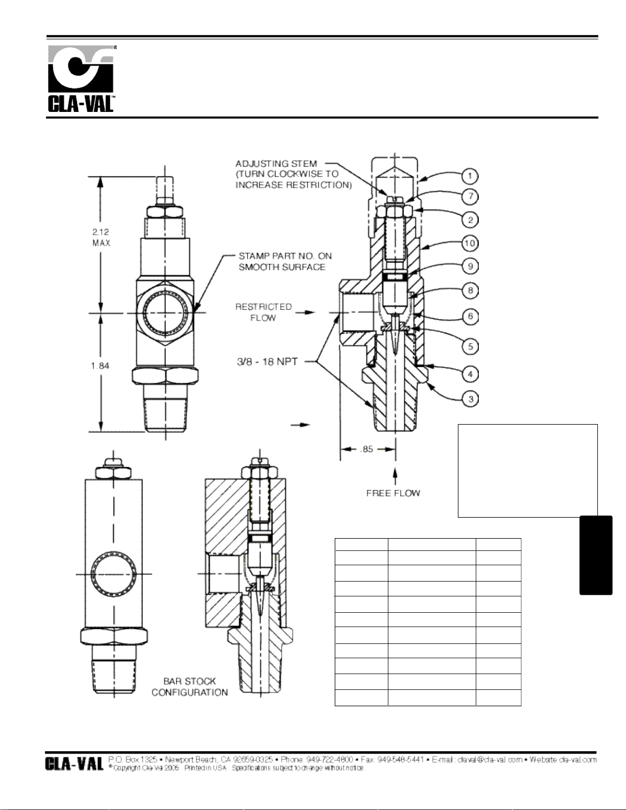
121
3/8" Flow Control
CV
When ordering parts,
please specify:
• Number Stamped on Side
• Description (CV Flow Control)
• Part Description
• Material
ITEM DESCRIPTION QUAN.
1 Cap (SS only) 1
2 Nut, Jam 1
3 Seat 1
4 Gasket 1
5 Disc 1
6 Spring 1
7 Ring, Retaining 1
8 Stem 1
9 O-Ring 1
10 Housing 1
PL-CV (R-5/05)
PARTS LIST
2
–
1
Page 43
122
*This drawing is the property of CLA-VAL and same and copies made thereof, if any, shall be returned to it upon demand. Delivery and disclosure hereof are made solely
upon condition that the same shall not be used, copied ore reproduced, nor shall the subject here of be disclosed in any manner to anyone for any purpose, except as
herein authorized, without prior approval of CLA-VAL. Whether or not the equipment or information shown hereon is patented or otherwise protected, full title and copyrights if any, in and to this drawing and/or information delivered or submitted are fully reserved by CLA-VAL.
Dwg#47117
Regulator Spring Color Coding Chart
THE FOLLOWING CONTROL & SPRING P/N#'S WERE REMOVED, 32656B, 31554K, 44591G, V65695B, & V5695B.
ADDED CRL-13, CRL-5A, CRA, CRA-10A, CHANGED SPRING RANGES TO MATCH CURRENT CONTROLS.
PL-47117 AD (R-11/06)
PARTS LIST
W
IRESIZE
S
PRINGNUMBER
C
OLOR
W
IREMATERIALCATALOGNUMBER
PSI R
ANGE
*PSI PERT
URN
.080 DIA. C0492D BLUE S.S.
CDB-7
CRL-5A
0-7
0-7
.75
.75
.018 DIA. 82575C -- S.S.
CRD
CRD-10A
1.9-6.5
1.9-6.5
.61
.49
.116 DIA. 81594E -- S.S.
CRD
CRD-10A
2-30
2-30
3.0
2.4
.120 DIA. V5654J GREEN CHR VAN
CRL-5A
CRD
5-25
10-40
4.0
4.0
.162 DIA. 32447F NATURAL S.S.
CDB-7
CRL-5A
CRL-13
10-60
10-60
10-60
12.0
12.0
12.0
.162 DIA. V5695B YELLOW MUSIC WIRE
CDB-7
CRL-5A
CRL-13
20-80
20-80
20-80
14.5
14.5
14.5
.207 DIA. C1124B CAD PLT MUSIC WIRE
CDB-7
CRL-13
CRL-5A
50-150
50-150
50-150
29.5
29.5
29.5
.225 DIA. V6515A RED MUSIC WIRE
CDB-7
CRL-13
CRL-5A
65-180
65-180
65-180
44.0
44.0
44.0
.115 X .218 71884B RED CHR VAN
CRL
CRD
CRD-10A
0-75
15-75
15-75
8.5
9.0
7.2
.118 X .225 71886J GREEN CHR VAN
CRL
CRD
CRD-10A
20-200
30-300
30-300
28.0
27.0
22.4
.225 X .295 1630201A CAD PLT CHR VAN
CRL
CRL-5A
100-300
100-300
18.00
18.00
.440 X .219 48211H CAD PLT STEEL
CRA-18
CRD-22
CRL-4A
200-450
200-450
100-450
17.0
17.0
17.0
.187 20561901H BLACK STEEL CRD 20-105 12.0
W
IRESIZE
S
PRINGNUMBER
C
OLOR
W
IREMATERIALCATALOGNUMBER
PSI R
ANGE
*F
EETPERTURN
.080 DIA. C0492D BLUE S.S.
CRA
CRD-2
4.5-15
4.5-15
.82
.82
.375 DIA.
87719B
1 SPRING
2 SPRING
3 SPRING
4 SPRING
5 SPRING
EPOXY
COATED
CHROME SILICON CDS-5
5-40
30-80
70-120
110-120
150-200
1.0
2.0
3.0
4.0
5.0
.072 DIA. V5097A -- 302SS CVC 1-17 .7
.375 DIA.
2933502H
1 SPRING
2 SPRING
3 SPRING
4 SPRING
5 SPRING
EPOXY
COATED
CHROME SILICON CDS-6
5-40
30-80
70-120
110-120
150-200
.75
1.50
2.20
3.00
3.70
*
THESE FIGURES ARE ONLY APPROXIMATE. FINAL ADJUSTMENTS SHOULD BE MADE WITH A PRESSURE GAGE.
Page 44
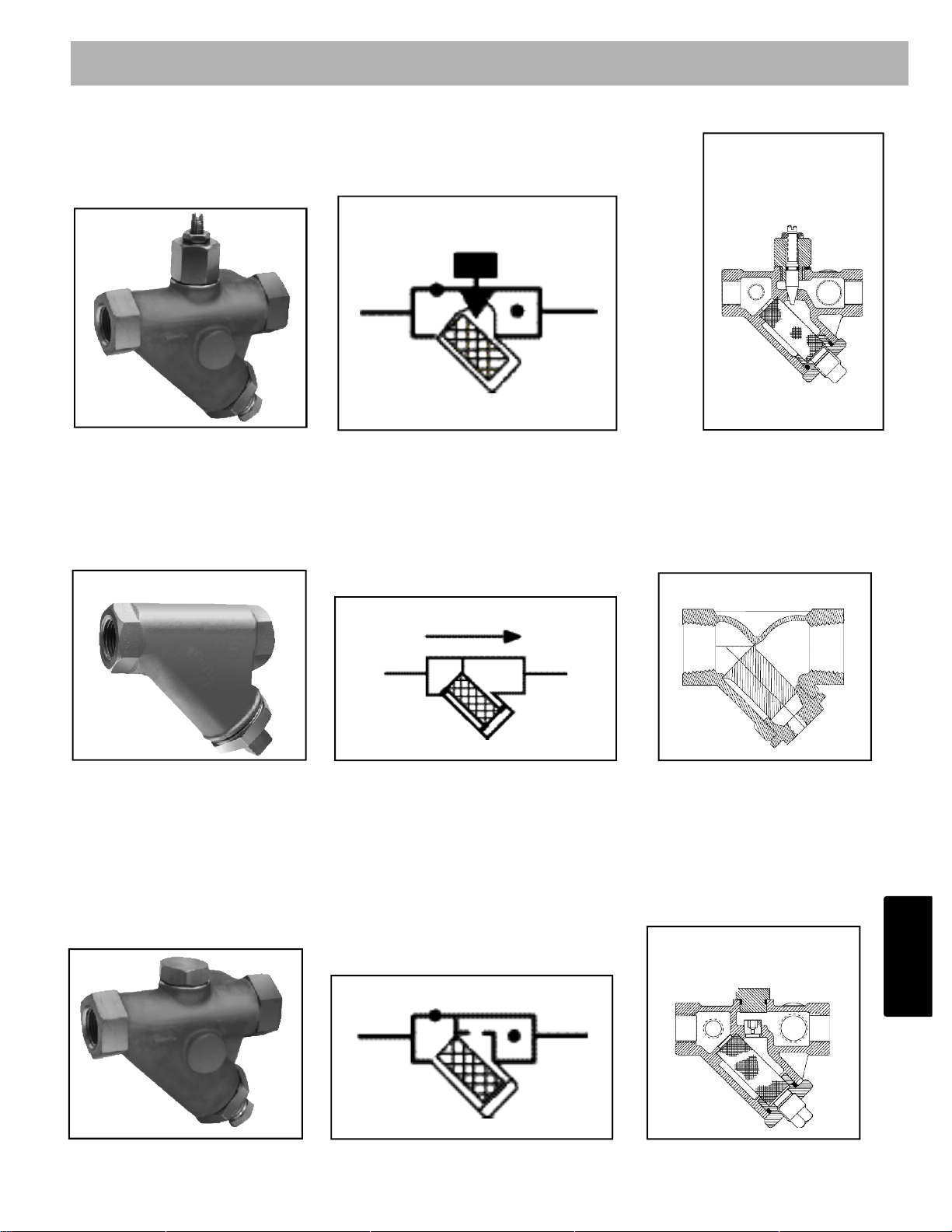
123
X42N-2 Strainer and Needle Valve Assembly
X42N-2
X42N-2
X42N-2
Schematic Symbol
X43- Y-Strainer
is used to keep solids out of the pilot system. The standard is 40 mesh (Note other materials available)
Available in 1/4" - 3/4" female NPT
Bronze body, brass plug, stainless steel screen
Maximum Working Pressure 400 psi
X43
X43
X43
Schematic Symbol
X44A Strainer and Orifice Assembly
X44A
X44A
X44A
Schematic Symbol
Accessories Identification
Section 2 - 2
2
–
2
Page 45
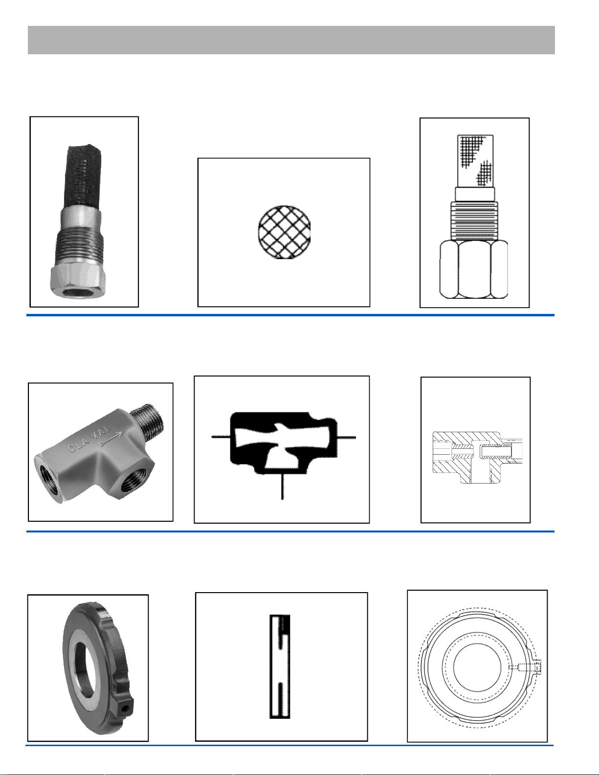
124
Accessories Identification
Section 2 - 2
X46
X46
X46
X46 Strainer
is designed to prevent passage of foreign particles larger than .015". It is especially effective against
such contaminant as algae, mud, scale, wood pulp, moss, and root fibers.
Schematic Symbol
X47A Ejector
X47A Ejector is a compact, precision fitting, incorporating a primary and a secondary jet, designed
to create a low-pressure area at the suction port.
X47A
X47A
X47A
Schematic Symbol
X52E Orifice Plate Assembly
X52E Orifice Plate Assembly is typically used with Cla-Val flow control valves. The orifice plate is an
essential component used to generate a specific predictable pressure drop in the system.
X52E
X52E
X52E
Schematic Symbol
Page 46

125
Accessories Identification
Section 2 - 2
X58C Restriction A s s e m b l y
is composed of a modified standard (45 degree flare) tube connector with a precision delrin orifice
fitting installed.
X58C
X58C
X58C
Schematic Symbol
X101 Valve Position Indicator -
is very helpful in troubleshooting
X101
X101
X101
Schematic Symbol
X102
Flow Limiting Assemblies
regulates flow through Cla-Val Automatic Valves from full flow to shut-off. These adjustable assemblies control flow by limiting the amount of the valve opening. Limited to 6" & smaller.
X102
X102
X102
Schematic Symbol
2
–
2
Page 47
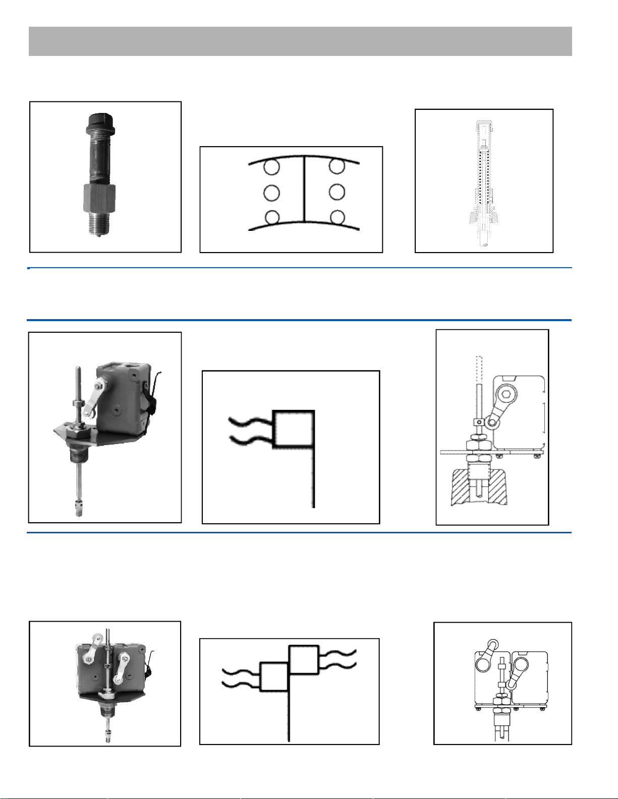
126
Accessories Identification
Section 2 - 2
X103 Spring Lift
X103
X103
X103
Schematic Symbol
X105LCW
Limit Switch Assemblies
X 1 0 5 L Limit Switch Assembly is a rugged, dependable and positive acting switch assembly actuated by the
opening or closing of a Cla-Val control valve on which it is mounted.
X105LCW
X105LCW
X105LCW
Schematic Symbol
X105L2W
Limit Switch Assemblies
X105L2 Limit Switch Assembly is a rugged, dependable and positive acting switch assembly actuated by
the opening or closing of a Cla-Val control valve on which it is mounted.
X105L2
X105L2
X105L2
Schematic Symbol
Page 48

127
X117C
X117C
X117C
X117C Valve Position Transmitter
is an accurate monitor of valve position. Through an industry standard 4-20 mA output, the X117C
delivers the level of accuracy required for computer control valve systems (SCADA type).
Schematic Symbol
Accessories Identification
Section 2 - 2
X117D Valve Position Transmitter
is an accurate monitor of valve position. Through an industry standard 4-20 mA output, the
X117D delivers the accuracy required for computer control valve systems (SCADA type).
X117D
X117D
X117D
Schematic Symbol
2
–
2
Page 49
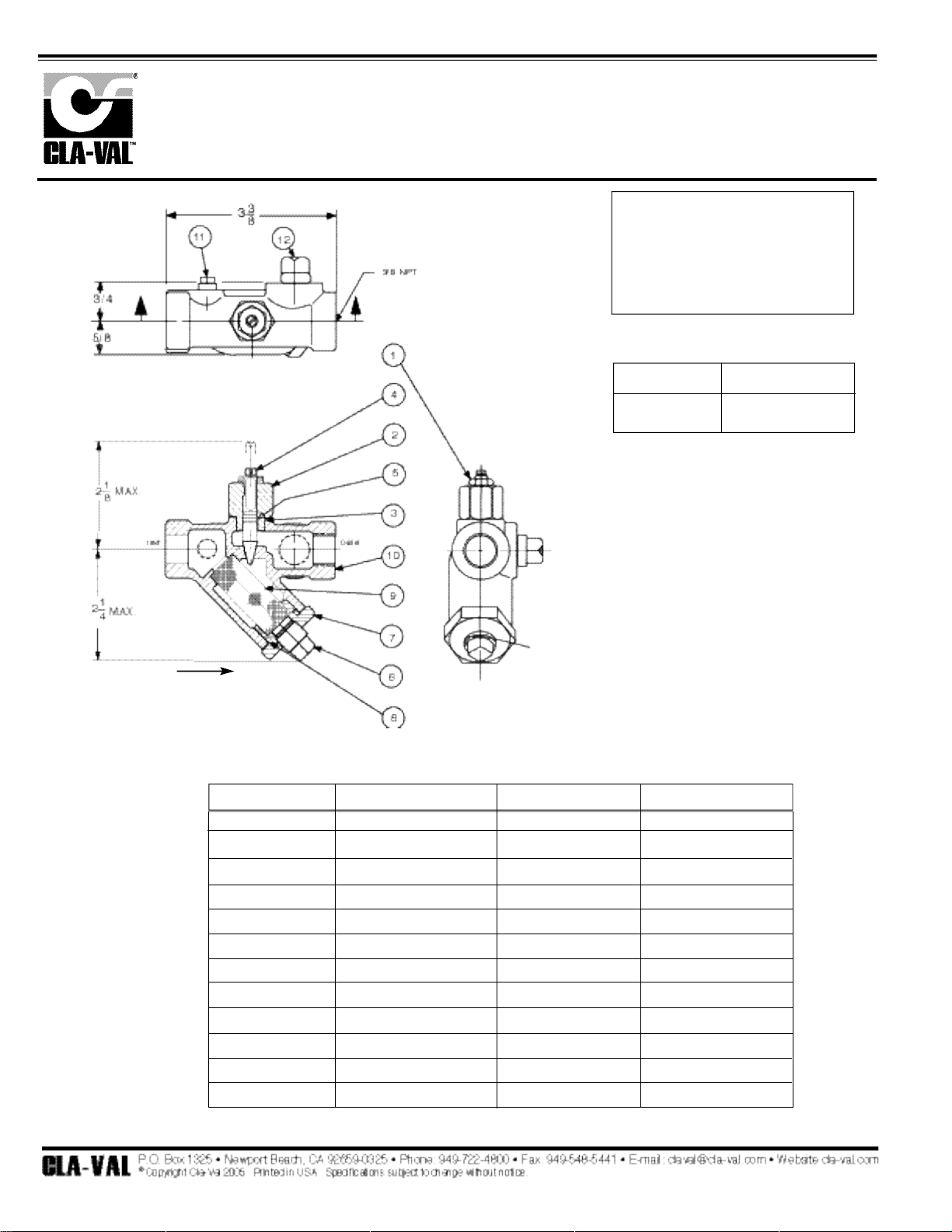
128
When ordering parts,
please specify:
• All nameplate data
• Item Number
• Description
Strainer and Needle Valve Assembly
X42N-2
Size Stock Number
3/8" x 3/8" 68372C
1
2
3
4
5
6
7
8
9
10
11
12
Jam Nut —Hex
Bonnet
"O" Ring—Bonnet
Stem
"O" Ring—Stem
Plug—Pipe 1/4
Strainer Plug
"O" Ring—Plug
Screen
Body
Plug—Pipe 1/8
Plug—Pipe 3/8
Sil Brz
S.S.
Syn Rub
S.S.
Syn Rub
Bre.
303
NBR
Monel
Rd Brs
Brass
Brass
ITEM DESCRIPTION MATERIAL PART NO.
PL- X42N-2 (R-5/05)
PARTS LIST
Page 50

ITEM DESCRIPTION MATERIAL
1 Pipe Plug Steel
2 Strainer Plug Brass
3 Gasket Copper
4 Screen SST
5 Body Brass
SIZE STOCK NUMBER
3/8 x 3/8 33450J
Strainer
X43
No parts available. Rreplacement assembly only.
Standard 60 mesh pilot system strainer for fluid service.
PL- X43 (R-12/06)
PARTS LIST
129
2
–
2
Page 51
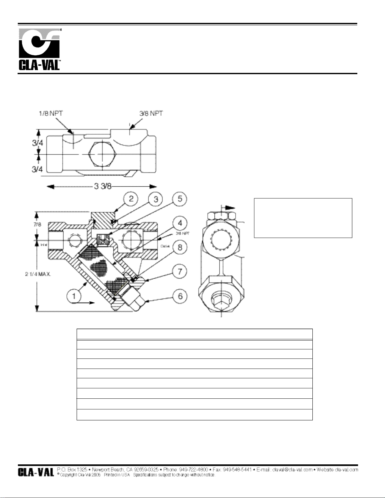
130
When ordering parts, please specify:
• All Nameplate Data
• Item Number
• Description
• Recommended Spare Parts
Strainer and Orifice Assembly
X44A
BRONZE BODY — S.S. ORIFICE
*
Standard
ITEM
1
2
3
4
5
6
7
8
DESCRIPTION
Body
Plug, Top
"O" Ring, Plug Top
Screen
Orifice Plug
Plug, Pipe
Strainer Plug
"O" Ring, Strainer Plug
MATERIAL
Red Brs.
Brass
Syn. Rub.
Monel
Delrin
Brass
S.S.
Syn. Rub.
QTY.
1
1
1
1
1
1
1
1
P-X44A (R-5/05)
PARTS LIST
Page 52
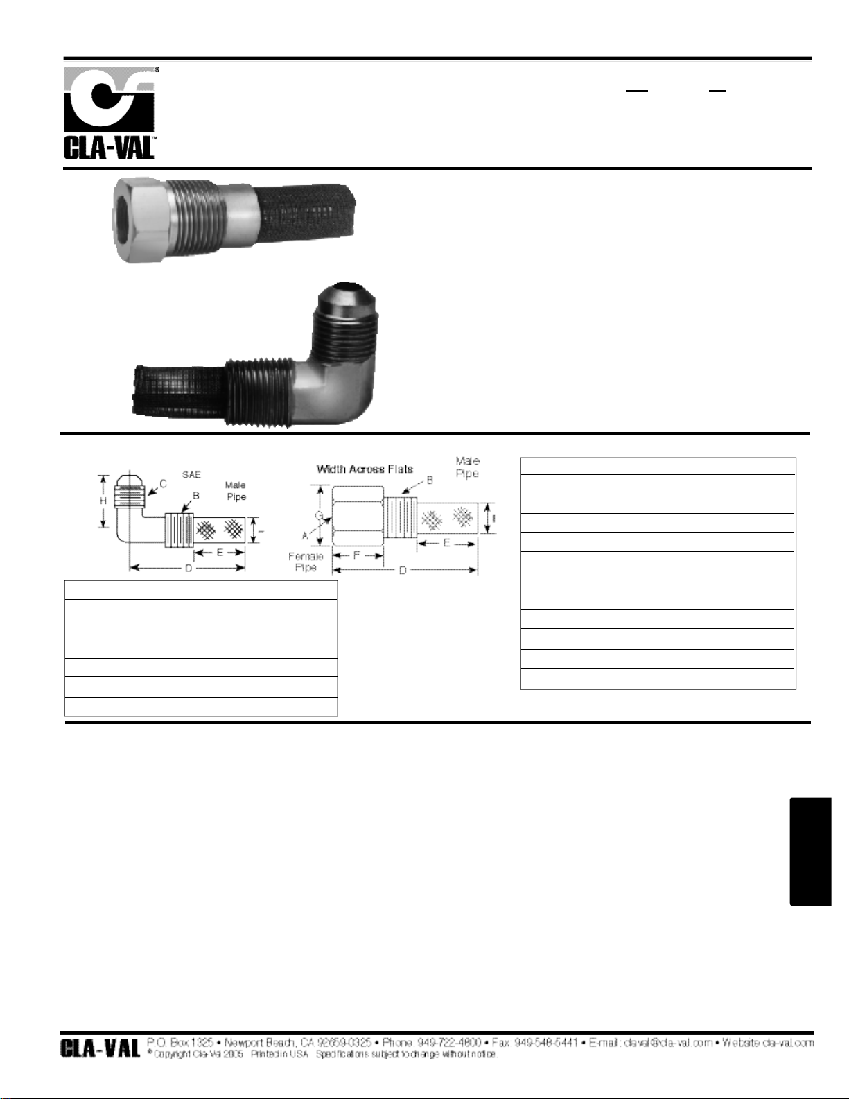
The strainer is designed for use in conjunction with a Cla-Val
Main Valve, but can be installed in any piping system where
there is a moving fluid stream to keep it clean. When it is used
with the Cla-Val Valve, it is threaded into the upstream body port
provided for it on the side of the valve. It projects through the
side of the Main Valve into the flow stream. All liquid shunted to
the pilot control system and to the cover chamber of the Main
Valve passes through the X46 Flow Clean Strainer.
• Self Scrubbing Cleaning Action
• Straight Type or Angle Type
The Cla-Val Model X46 Strainer is designed to prevent passage of
foreign particles larger than .015". It is especially effective against
such contaminant as algae, mud, scale, wood pulp, moss, and root
fibers. There is a model for every Cla-Val. valve.
The X46 Flow Clean strainer operates on a velocity principle utilizing the circular "air foil" section to make it self cleaning. Impingement
of particles is on the "leading edge" only. The low pressure area on
the downstream side of the screen prevents foreign particles from
clogging the screen. There is also a scouring action, due to eddy
currents, which keeps most of the screen area clean.
Dimensions
(In Inches)
INSTALLATION
X46 Angle Type B (In Inches)
B
(NPT)C(SAE)
D E H I
1/8 1/4 1-3/8 5/8 7/8 1/4
1/4 1/4 1-3/4 3/4 1 3/8
3/8 1/4 2 7/8 1 1/2
3/8 3/8 1-7/8 7/8 1 1/2
1/2 3/8 2-3/8 1 1-1/4 5/8
X46A Straight
X46B Angle
X46A Straight Type A (In Inches)
A B D E F G I
1 / 8 1 / 8 1 - 3 / 4 3 / 4 1 / 2 1 / 2 1 / 4
1 / 4 1 / 4 2 - 1 / 4 1 3 / 4 3 / 4 3 / 8
3 / 8 3 / 8 2 - 1 / 2 1 7 / 8 7 / 8 1 / 2
3 / 8 1 / 2 2 - 1 / 2 1 - 1 / 4 1 / 2 7 / 8 3 / 4
1 / 2 1 / 2 3 1 - 1 / 4 1 1 - 1 / 8 3 / 4
3 / 8 3 / 4 3 - 3 / 8 2 1 / 2 1 7 / 8
3 / 4 3 / 4 4 2 1 1 - 1 / 2 7 / 8
3 / 8 1 4 - 1 / 4 2 - 3 / 4 1 / 2 1 - 3 / 8 7 / 8
1 1 4 - 1 / 2 2 - 3 / 4 1 - 1 / 4 1 - 3 / 4 7 / 8
1 / 2 1 4 - 1 / 4 2 - 3 / 4 1 / 2 1 - 3 / 8 7 / 8
Flow Clean Strainer
X46
INSPECTION
Inspect internal and external threads for damage or evidence
of cross-threading. Check inner and outer screens for clogging,
embedded foreign particles, breaks, cracks, corrosion, fatigue,
and other signs of damage.
CLEANING
After inspection, cleaning of the X46 can begin. Water service usually will produce
mineral or lime deposits on metal parts in contact with water. These deposits can
be cleaned by dipping X46 in a 5-percent muriatic acid solution just long enough for
deposit to dissolve. This will remove most of the common types of deposits.
Caution: use extreme care when handling acid. If the deposit is not removed
by acid, then a fine grit (400) wet or dry sandpaper can be used with water.
Rinse parts in water before handling. An appropriate solvent can clean parts
used in fueling service. Dry with compressed air or a clean, lint-free cloth.
Protect from damage and dust until reassembled.
REPLACEMENT
If there is any sign of damage, or if there is the slightest doubt that the Model
X46 Flow Clean Strainer may not afford completely satisfactory operation,
replace it. Use Inspection steps as a guide. Neither inner screen, outer screen, nor
housing is furnished as a replacement part. Replace Model X46 Flow Clean Strainer
as a complete unit.
When ordering replacement Flow-Clean Strainers, it is important to determine pipe
size of the tapped hole into which the strainer will be inserted (refer to column A or
F), and the size of the external connection (refer to column B or G).
When Ordering,
Please Specify:
• Catalog Number X46
• Straight Type or Angle Type
• Size Inserted Into and Size Connection
• Materials
DISASSEMBLY
Do not attempt to remove the screens from the strainer housing.
M O D E L
INSTALLATION / OPERATION / MAINTENANCE
N-X46 (R-5/05)
(NPT) (NPT)
X46B
X46A
131
2
–
2
Page 53

132
DESCRIPTION
The Cla-Val Model X47A Ejector is a compact, precision fitting, incorporating a primary and a secondary jet, designed to create a low-pressure area at the suction port.
DISASSEMBLY
Do not attempt to remove primary or secondary jets from X47A
Ejector housing.
CLEANING
After inspection, cleaning of the X47A can begin. Water service
usually will produce mineral or lime deposits on metal parts in contact with water. These deposits can be cleaned by dipping the X47A
in a 5-percent muriatic acid solution just long enough for deposits to
dissolve. This will remove most of the common types of deposits
Caution: use extreme care when handling acid. If the deposit is
not removed by acid, then a fine grit (400) or dry sandpaper can be
used with water. Rinse parts in water before handling. An appropriate solvent can clean parts used in fueling service. Dry with compressed air or a clean, lint-free cloth. Protect from damage and dust
until reassembled.
REPLACEMENT
If there is any sign of damage, or if there is the slightest doubt that
the X47A Ejector may not afford completely satisfactory operation,
replace it. Use Inspection steps as a guide. Neither the primary jet,
secondary jet, or bare housing is furnished as a replacement part.
Replace X47A Ejector as a complete unit.
OPERATION
The X47A Ejector is designed for use in a pilot control system on a ClaVal Main Valve. Pressure is applied to the inlet port (A). As the fluid
passes through the center portion of the X47A Ejector, the high velocity entrains particles of fluid from suction port (B), which results in a
reduced pressure at this port.
In actual operation, the pressure port (A) is connected to the upstream
side of the Main Valve; the discharge port (C) is connected to the Pilot
Control; and the suction port (B) is connected to the cover chamber of
the Main Valve.
Fluid line pressure enters at the inlet port (A). When the Pilot Control
is closed, no flow occurs through the X47A Ejector, and full line pressure is directed into the Main Valve cover chamber, closing the Main
Valve tight. As the Pilot Control opens, and flow through the X47A
Ejector begins, pressure at the suction port (B) decreases until the
Main Valve is permitted to open. Further changes in the flow rate
resulting from opening and closing of the Pilot Control produce corresponding changes in the flow through the Main Valve.
Ejector
X47A
INSPECTION
Inspect port threads for damage or evidence of cross-threading.
Check primary and seco ndary jets for clogging or em bedd ed foreign particles. Check for breaks , cracks, fatigue, and other signs
of damage.
M O D E L
INSTALLATION / OPERATION / MAINTENANCE
N-X47A (R-1/06)
Page 54

133
X52E
Orifice Plate Assembly
MODEL
2
–
2
Dimensions
The Cla-Val Model X52E Orifice Plate Assembly is typically used with
Cla-Val flow control valves. The orifice plate is an essential component
used to generate a specific, predictable pressure drop in the system.
The X52E uses a wafer design holder which offers a compact lightweight assembly that is easy to install. The X52E has a Chamfered
"Inlet" side so even after installation, correct orientation can be easily
verified.
The orifice plate portion of the assembly is made of 302 stainless steel
with other materials options also available. The plate is machined to a reco m m e n d ed "square edge". The plate holder portion of the assembly is
Ductile Iron standard. Fusion-bonded epoxy coating is an option. The
holder may be made of other materials.
Selecting an orifice plate bore size is made by using charts provided.
We recommend installation of this assembly with the sensing port to the
side of the pipeline to prevent air pockets and obstructions in the sensing line. Installation adjacent to a butterfly valve is not recommended as
the orifice plate assembly may interfere with the opening of this type of
valve.
NOMINAL PIPE SIZE (inches) 1
1
⁄
2
2 2
1
⁄
2
3 4 6 8 10 12 14 16
Diameter of Flange 3.63 4.25 5.00 5.75 7.00 9.75 12.00 14.12 16.50 19.00 21.12
Diameter of Raised Face 2.88 3.63 4.13 5.00 6.19 8.50 10.63 12.75 15.00 16.25 18.50
"A" Dim from CL to top of boss 2.31 2.62 3.00 3.38 4.00 5.38 6.50 7.62 8.75 10.00 11.06
Diameter of Bolt Circle (B.C.D.) 3.88 4.75 5.50 6.00 7.50 9.50 11.75 14.25 17.00 18.75 21.25
150 Lb. Number of Bolts 4 4 4 4 8 8 8 12 12 12 16
Radius of Bolt Holes .31 .38 .38 .38 .38 .44 .44 .50 .50 .56 .56
300 Lb. Diameter of Bolt Circle 4.50 5.00 5.50 6.63 7.88 10.63 13.00 15.25 17.75 20.25 22.50
Number of Bolts 4 8 8 8 8 12 12 16 16 20 20
• Wafer Design
• Fits ANSI 125, 150, 250, 300
• Optional Materials Available
• Easy to use size Selection Chart
Page 55
134
Bore
Flow — gpm
Size Min Max Nominal
4.60 490 1960 1100
4.40 435 1740 980
4.20 380 1520 850
4.00 330 1320 750
3.80 300 1200 670
3.60 265 1060 590
3.40 230 920 520
3.20 200 800 450
3.00 175 700 395
2.80 150 600 340
2.60 130 520 295
2.40 110 440 245
Bore
Flow — gpm
Size Min Max Nominal
4.60 490 1960 1100
4.40 435 1740 980
4.20 380 1520 850
4.00 330 1320 750
3.80 300 1200 670
3.60 265 1060 590
3.40 230 920 520
3.20 200 800 450
3.00 175 700 395
2.80 150 600 340
2.60 130 520 295
2.40 110 440 245
2"* Valve/Pipe Size
*For 1
1/2
" bore information please consult the factory
1. In determining a bore size, the nominal flow rate (or range of flow) and the pipe size in which the orifice plate assembly will
be installed must be known.
2. Sizing a bore for:
A constant flow rate:
Select the sizing chart that matches pipe size and locate the flow rate under the nominal column which is closest to
required flow; select the corresponding bore size dimension.
Sizing An Orifice Plate Bore
Orifice Plate Bore Chart
Example:
A 6" pipe with a desired constant flow of 700
gpm
.
Using the 6" chart, the closest flow in the nominal
column is 670
gpm
which has a corresponding bore
size of 3.80".
A flow range:
Select the sizing chart that matches pipe size and locate required flow range between the minimum and maximum limits of an
orifice bore. Frequently the flow range will fit between more than one bore size. To resolve this, decide the flow rate that
system will be operated at most frequently. Locate the flow which is closest to this under the nominal flow column, and
select the corresponding bore size dimension.
Example:
A 6" pipe with a flow range of 300-1000 gpm. Using
the 6" chart, more than one bore size can accommodate this range. The most frequent flow rate will
be 500 gpm. Using the nominal flow column, the
closest flow is 520 gpm which has a corresponding
bore size of 3.40"
Bore
Flow — gpm
Size Min Max Nominal
1.55 55 220 125
1.50 50 200 115
1.40 42 168 95
1.20 29 116 65
1.00 19 76 45
.80 12 50 28
6" Valve/Pipe Size
6" Valve/Pipe Size
21⁄2" Valve/Pipe Size
Bore
Flow — gpm
Size Min Max Nominal
1.87 80 330 180
1.60 55 220 120
1.40 40 160 88
1.20 28 115 62
1.00 19 80 43
.80 12 50 28
Page 56

135
2
–
2
Bore Flow — gpm
Size Min Max Nominal
4.60 490 1960 1100
4.40 435 1740 980
4.20 380 1520 850
4.00 330 1320 750
3.80 300 1200 670
3.60 265 1060 590
3.40 230 920 520
3.20 200 800 450
3.00 175 700 395
2.80 150 600 340
2.60 130 520 295
2.40 110 440 245
6" Valve/Pipe Size
Bore Flow — gpm
Size Min Max Nominal
7.50 1300 5200 2900
7.00 1075 4300 2400
6.50 880 3520 1950
6.00 730 2920 1650
5.50 600 2400 1350
5.00 490 1960 1100
4.50 390 1560 870
4.00 310 1240 690
3.50 235 940 525
3.00 175 700 385
10" Valve/Pipe Size
Bore Flow — gpm
Size Min Max Nominal
9.00 1850 7400 4200
8.50 1575 6300 3500
8.00 1350 5400 3000
7.50 1150 4600 2600
7.00 980 3920 2200
6.50 840 3360 1875
6.00 700 2800 1575
5.50 580 2320 1300
5.00 480 1920 1075
4.50 385 1540 870
12" Valve/Pipe Size
Bore Flow — gpm
Size Min Max Nominal
6.00 830 3320 1850
5.80 760 3040 1700
5.60 680 2720 1550
5.40 620 2480 1400
5.20 570 2280 1275
5.00 515 2060 1150
4.80 470 1880 1050
4.60 425 1700 950
4.40 385 1540 860
4.20 345 1380 780
4.00 310 1240 700
8" Valve/Pipe Size
Bore Flow — gpm
Size Min Max Nominal
2.29 120 480 270
2.20 105 420 240
2.00 84 336 190
1.80 65 260 145
1.60 50 200 115
1.40 38 152 86
1.20 28 112 62
1.00 19 76 43
Bore Flow — gpm
Size Min Max Nominal
3.00 205 820 450
2.80 170 680 390
2.60 140 560 310
2.40 115 460 260
2.20 96 384 215
2.00 78 312 175
1.80 63 252 140
1.60 49 196 110
1.40 38 152 84
1.20 28 112 62
3" Valve/Pipe Size 4" Valve/Pipe Size
Page 57
136
Bore Flow — gpm
Size Min Max Nominal
17.00 8500 25500 15000
16.00 7500 21500 12500
15.00 6100 18400 10500
14.50 5700 17000 9800
14.00 5200 15600 9000
13.50 4800 14400 8300
13.00 4400 13200 7600
12.50 4000 12100 7000
12.00 3700 11100 6400
11.50 3400 10100 5800
11.00 3100 9200 5300
10.50 2800 8300 4800
10.00 2500 7500 4400
Bore Flow — gpm
Size Min Max Nominal
26.00 20000 60000 35000
24.00 16000 48500 28000
22.00 13000 39000 22500
21.00 12000 35000 20500
20.00 10500 31000 18000
19.00 9500 28000 16000
18.00 8500 24500 14500
17.00 7500 22000 12500
16.00 6500 19300 11000
15.00 5600 16900 9800
14.00 4900 14600 8500
13.00 4200 12600 7300
Bore Flow — gpm
Size Min Max Nominal
13.00 5200 15500 9000
12.00 4100 12300 7100
11.50 3700 11000 6400
11.00 3300 9850 5700
10.50 2950 8800 5100
10.00 2600 7850 4550
9.50 2350 6200 3600
9.00 2100 6200 3600
8.50 1850 5500 3200
8.00 1650 4850 2800
7.50 1400 4250 2450
7.00 1250 3650 2100
14" Valve/Pipe Size
16" Valve/Pipe Size
Bore Flow — gpm
Size Min Max Nominal
10.00 2350 9400 5200
9.50 2025 8100 4500
9.00 1750 7000 3900
8.50 1500 6000 3400
8.00 1300 5200 2900
7.50 1150 4600 2500
7.00 960 3840 2150
6.50 820 3280 1850
6.00 700 2800 1550
5.50 585 2340 1300
5.00 480 1920 1075
4.50 385 1540 860
Bore Flow — gpm
Size Min Max Nominal
11.50 3100 12400 7000
11.00 2700 10800 6100
10.50 2400 9600 5400
10.00 2100 8400 4700
9.50 1850 7400 4200
9.00 1650 6600 3650
8.50 1450 5800 3250
8.00 1250 5000 2850
7.50 1100 4400 2450
7.00 950 3800 2150
6.50 810 3240 1800
6.00 700 2800 1550
5.50 575 2300 1300
18" Valve/Pipe Size
24" Valve/Pipe Size
Bore Flow — gpm
Size Min Max Nominal
14.00 6000 18000 10500
13.50 5300 16000 9500
13.00 4800 14500 8500
12.50 4300 12900 7500
12.00 3900 11700 6700
11.50 3400 10500 6100
11.00 3200 9500 5500
10.50 2900 8600 5000
10.00 2600 7700 4500
9.50 2300 6100 3600
9.00 2000 6100 3600
8.50 1800 5400 3200
20" Valve/Pipe Size
36" Valve/Pipe Size
E-X52E (R-2/06)
Represented By:
Page 58

137
X-52 Series Orifice Assemblies
The X52 Series Orifice Assembly consists of a calibrated, precision-machined orifice plate and
flange holder. It is typically supplied with 40 Series valves. Flange holder material is same as
main valve body. The 1/8" thick orifice plate (X55A) is made of 303 Stainless Steel with 316
Stainless Steel optional. Small screws hold the orifice plate into the holder (at approximately
half the thickness of holder) on X52B and X52D-1 assemblies. The orifice plate is staked in
place (at inlet side) on X52A-1 and X52E assemblies. The X52 is assembled prior to epoxy
coating when an epoxy coated main valve is specified (orifice bore is masked). Pressure class
(125/150 or 250/300) must be specified for proper fit in pipeline. X52E is a wafer style redesign
of the X52A-1 and is suitable for 150 and 300 class flanges.
X55A is catalog number for orifice plate used in X52 assemblies. Typically used for replacement
in existing holders or for installation in customer supplied flange holder.
X55B is catalog number for paddle type orifice plate installed between two pipe flanges. Paddle
handle is stamped with bore size. For flow control applications, two pipeline tap connections for
pilot valve sensing must be customer supplied. When used for cavitation control it is typically
mounted downstream of control valve. Pressure class (125/150 or 250/300) must be specified
for proper fit in pipeline.
Cat. No. Dwg. Sensing Holes Thickness Comments
X52E 201278 One 1/4" NPT 1" NEW wafer style assembly.
for downstream Replaces X52A-1(after Jan 2001).
sensing Suitable for 150 and 300 class
flanges. Used with CDHS-18 pilot
Intended for downstream of valve.
X52A-1 81225 One 1/4" NPT Current assembly. Replaced old 2
for downstream 1" sensing hole assembly when we
sensing changed pilot from CDHS-2 to
CDHS-18. (circa mid 1970's)
Intended for downstream of valve.
X52B 41241 Two 1/8" NPT for 3/4" Obsolete. For AF valves and
sensing DP available in aluminum or steel
only. Used with CDHS-2 pilot.
Intended for upstream of valve.
X52D-1 43831 -Two 1/8" NPT for 1 1/2" Current assembly.
sensing DP Used with CDHS-2 pilot.
-One 1/2" NPT for Intended for upstream of valve.
pilot supply
2
–
2
Page 59
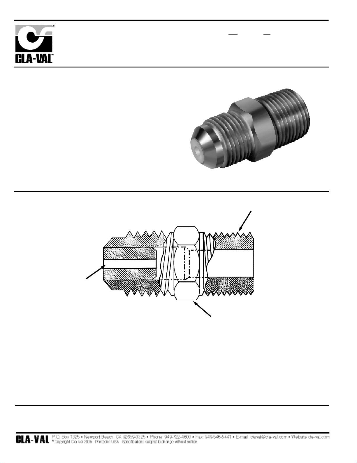
138
Restriction Assembly
X58C
Description
The Cla-Val Model X58C Restriction Assembly
is composed of a modified standard (45 degree flare) tube
connector with a precision delrin orifice fitting installed.
Flow direction is from tube to pipe connections. Orifice
size color code is stained onto brass tube connector
wrench flats. The X58C is installed as a part of pilot control systems on Cla-Val Valves.
Note: No replacement parts available - to be sold as complete assembly only.
When ordering please specify: Valve size, Stock Number
Restriction Orifice
Wrench Flats
(Color Stained)
N.P.T.
M O D E L
INSTALLATION / OPERATION / MAINTENANCE
N-X58C (R-5/05)
Page 60
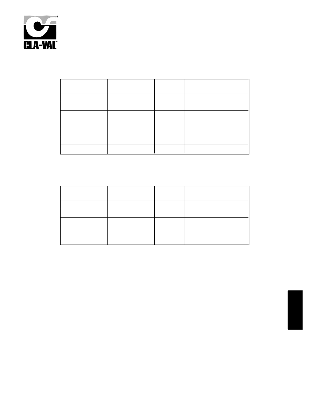
139
2
–
2
X58C Pilot System Orifice Restriction Fittings
SUITABLE FOR 3" AND SMALLER VALVES (BLUE)
Size TxNPT
Orifice Mat’l
Part Number
3/8" x 3/8"
3/8" x 3/8"
3/8" x 3/8"
3/8" x 3/8"
3/8" x 3/8"
3/8" x 3/8"
3/8" x 3/8"
.094 (3/32)
.094 (3/32)
.094 (3/32)
.094 (3/32)
.062 (1/16)
.062 (1/16)
.062 (1/16)
BP
BS
TP
TS
BP
BS
TP
68565B (std)
9932901D
9787003E (SWS)
9787015J
46946A
64672K
9787001J
SUITABLE FOR 4" AND LARGER VALVES (RED)
Size TxNPT Orifice Mat’l Part Number
3/8" x 3/8"
3/8" x 3/8"
3/8" x 3/8"
3/8" x 3/8"
3/8" x 3/8"
.125 (1/8)
.125 (1/8)
.125 (1/8)
.125 (1/8)
.188 (3/16)
BP
BS
TP
TS
BP
64673H (std)
4883405F
9787002G (SWS)
9787016G
43302K
Made from Tube Connector (Male Tube x Male NPT)
Material CODE
1st letter = fitting, 2nd letter = orifice insert
B = Brass
P = Delrin Plastic
S = 303 Stainless Steel
T = 316 Stainless Steel Parker fitting
NOTE:
High Differential Pressure (100+dpsi) over time can cause
Delrin orifice to extrude or copper tubing to erode.
Usually recommend upgrade to Stainless Steel.
Page 61

140
Valve Position Indicator
X-101
When ordering parts,
please specify:
• All Nameplate data
• Item Number
• Description
• Material
• Part Number
ITEM DESCRIPTION MATERIAL
1 Vent Valve Brass
2 Housing Brass
3 *Gasket
(2 Required) Buna-N
®
4 *Sight Tube Pyrex
5 Adapter Brass
6 Busing Brass
7 Stem Brass
8 Stem Adapter Brass
COMPLETE X101- BRONZE
1 1/4 - 1 1/2 C2812A
2 C8972G
2 1/2 C2607E
3 C2609A
4 9710001A
6 9710002J
8 C8581F
10 C9187A
12 31420D
14 30256C
16 30251D
SIZE STOCK NO.
PL- X101 (R-5/05)
PARTS LIST
*
Repair Kit Parts
Page 62

141
Model
50-01
Specifications
X102A
X102A
X102B
When Ordering, Please Specify
• Automatic Operation
• Corrosion Resistant
• No Lubrication
• Easy Adjustment
• Easy Maintenance
The Cla-Val Model X102 Flow Limiting Assemblies regulate
flow through Cla-Val Automatic Valves from full flow to shut-off .
These adjustable assemblies control flow by limiting the
amount of the valve opening.
The X102A and X102D maintain a pressure seal during adjustment by means of an internal “O" Ring.
The X102B is pressure sealed by means of an external
resilient washer, compressed when the Jam Nut is tightened,
after a d j u s t m e n t .
X102D
X102D
Pressure Ratings:
Valves 1/2" through 3" ..............150 psi maximum
Valves 4" and 6"..........................100 psi maximum
Valves 8".......................................30 psi maximum
Valves 10".....................................20 psi maximum
Materials:
Body (all models) ...........................................Brass
Stem X102A .............................303 Stainless Steel
X102B ...........................................................Brass
X102D ...........................................................Brass
When ordering please specify the following
information:
1. Flow Limiting Assembly Catalog Number
2. Valve Catalog Number
3. Valve Size
Flow Limiting Assembly
& Pilot System Components
X102B
X102
MODEL
E-X102 (R-5/05)
2
–
2
Page 63
142
Spring Lift
X103
DESCRIPTION
The Spring Lift Assembly is externally mounted on the Clayton valve cover, and houses an extension stem and a compression spring. The upper nd of the extension stem is threaded to provide
spring tension adjustment, the lower end is attached to the valve stem.
OPERATION
The Spring Lift Assembly is designed to assure a wide open valve position. This is a normal position when there is no pressure in the main valve cover chamber, under static and during certain
flowing conditions. An independent source of operating pressure generally will be required when
low line pressure exists.
ADJUSTMENT
Normally, the tension on the spring should be great enough to hold the valve wide open when
the system is not in use. This adjustment can be made before the valve is installed. If the valve
is installed. If the valve is in the system, remove all pressure before proceeding. (Refer to P-X103
sectional view).
1. Remove cap 1 and nipple 2.
2. Lift the spring lift stem 6 manually. If any upward travel is evident, increase spring tension
until no upward travel is felt. If no upward travel is felt it can be assumed the adjustment has been
made. However, to insure that too much tension has not been applied previously, decrease the
spring tension until an upward travel can be felt when pulling on the spring stem; then carefully
increase the spring tension until the upward travel has been removed.
To increase spring tension:
1. Loosen jam nut 3.
2. Turn lower adjusting nut clockwise until proper tension is obtained.
3. Tighten jam nut 3.
4. Replace nipple 2 and cap 1.
To decrease jam nut 3.
1. Loosen jam nut 3.
2. Turn lower adjusting nut counter-clockwise until proper spring tension is obtained.
3. Tighten jam nut 3.
4. Replace nipple 2 and cap 1.
CAUTION The Spring Lift Assembly will pull the valve open should the
Independent Operating Pressure Fail. Consult factory for complete details.
M O D E L
INSTALLATION / OPERATION / MAINTENANCE
N-X103 (R-1/07)
Page 64
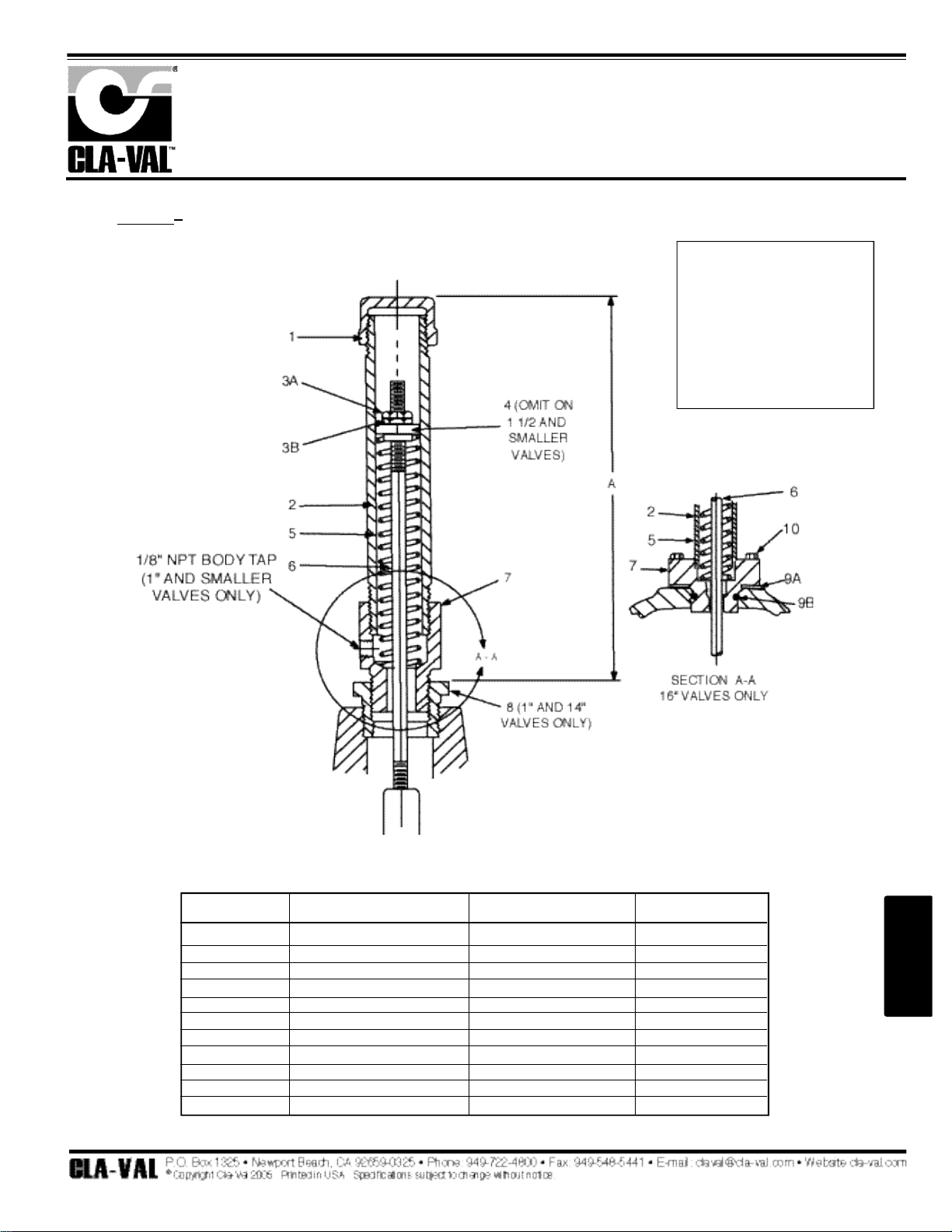
143
DIMENSIONS
PARTS LIST
Spring Lift
X103
When ordering parts,
please specify:
• All nameplate data
• Item Number
• Description
• Material
• Part Number
CAUTION The Spring Lift Assembly will pull the valve open should the
Independent Operating Pressure Fail. Consult factory for complete details.
ITEM NO.
1
2
3
4
5
6
7
8
9
10
DESCRIPTION
Pipe Cap
Nipple
Nut
Spring Guide
Spring
Stem
Body
Pipe Bushing
Gasket
Cap Screw
Valve Size - Inches
1/2 - 3/4 - 1
1 1/2
2- 2 1/2
3
4
6
8
10
12
14
16
Dimension A
3.75
3.31
3.75
6.13
7.25
9.13
10.00
17.50
26.50
24.00
19.50
PL- X103 (R-5/05)
PARTS LIST
2
–
2
Page 65
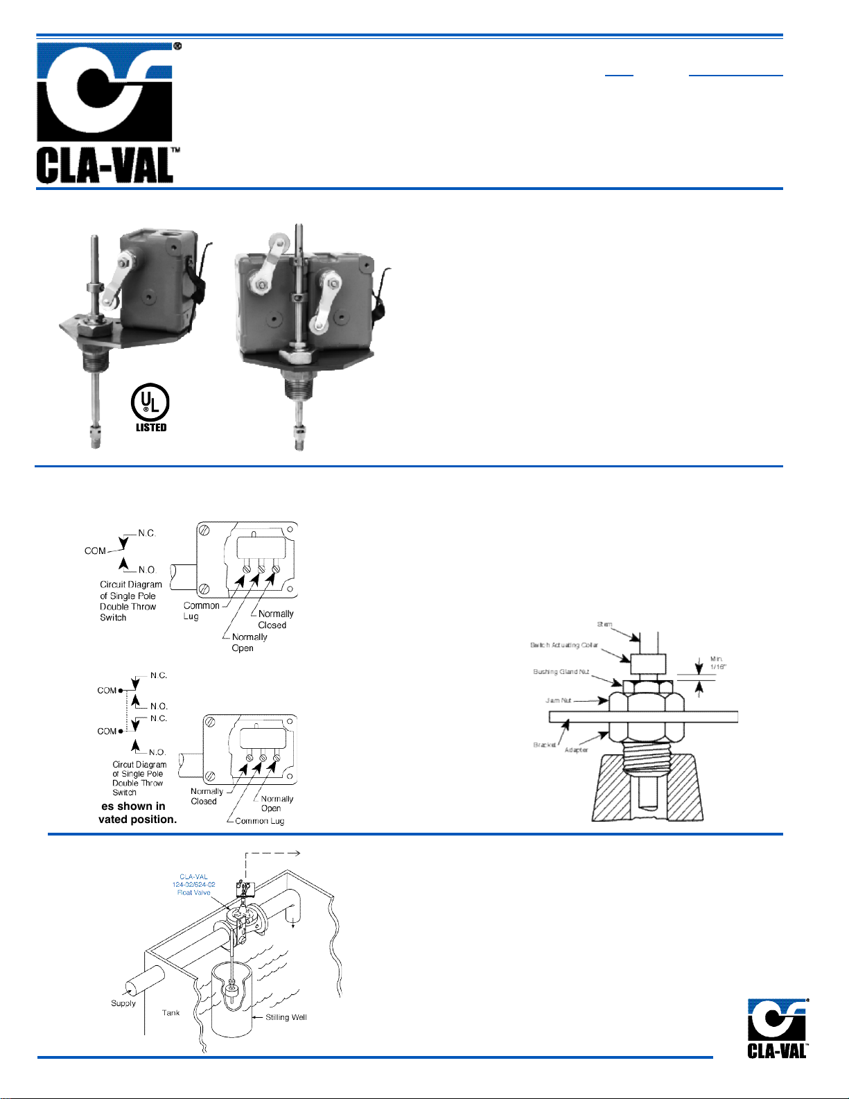
144
Switches shown in
unactivated position.
Double Pole Double Throw Switch
Single Pole Double Throw Switch
Limit Switch Assemblies
Installation
Typical Application
Actuating Collar Adjustment
Minimum Setting
When adjusting actuating collar for proper switch
action, a clearance of at least 1/16" (1/8" for 24"
valve) must be provided between the collar and
the bushing gland nut when valve is in the fully
closed position.
Used for any electrical operation which can be
performed by either opening or closing a switch;
such as alarm systems, process control, pump
control, motor starting or stopping, etc. Readily
attached to most Cla-Val Valves.
1. Remove plug in top of
valve cover.
2. Screw actuating stem
into main valve stem.
3. Slip adapter down
over stem and screw
into place on valve
cover.
4. Attach micro switch
housing and bracket to
adapter with jam nut.
5. Bring electrical supply
circuit into unit through
the 1/2" tapping in
micro switch housing.
6. Adjust switch collars.
(Set collar to trip
switch after valve is
positioned fully open
or fully closed)
• UL Listed Switches
• Positive Action
• Rugged and Dependable
• Weather Proof or Explosion Proof
• Easy To Adjust
The Cla-Val Model X105L/X105L2 Limit Switch Assembly is a rugged,
dependable and positive acting switch assembly actuated by the
opening or closing of a Cla-Val control valve on which it is mounted.
The single pole, double throw micro switch can be connected either
to open or to close an electrical circuit when actuated. By loosening
the allen screw on the actuating collar and raising or lowering the collar on the stem, the X105L is easily adjusted to signal that the valve
has fully reached the desired position (open or closed).
X105L
X105L2
MODEL
Switch only
Annunciator
Alarm
Page 66
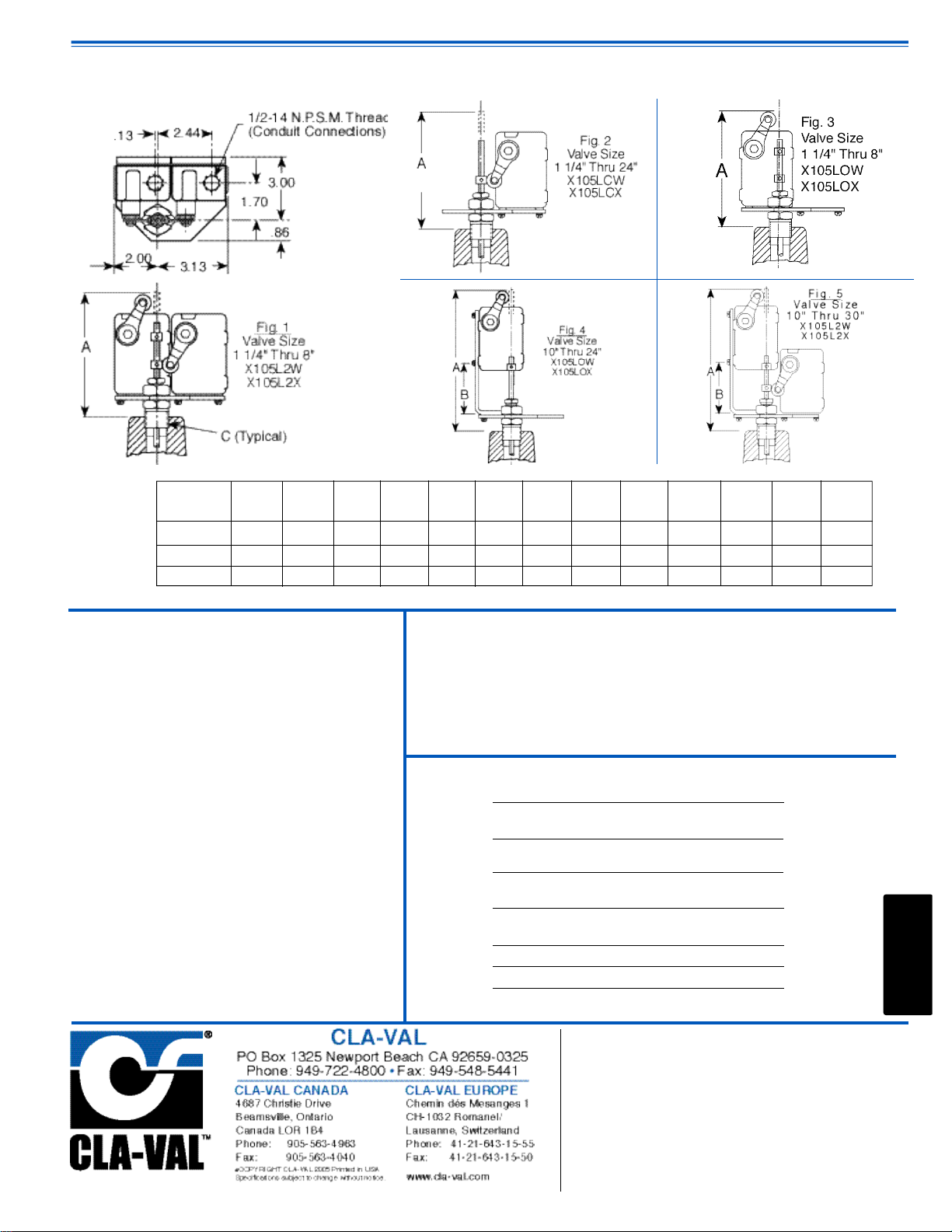
2
–
2
Dimensions
(In Inches)
When Ordering, Please Specify
1 . Valve Size 6 . Amperes and Voltage, AC or DC
2 . Catalog Number from Table Below 7 . Actuating Position (Valve Open or Closed)
3 . All Valve Name Plate Data
4 . Select Single or Double Pole Switch
5 . Explosion Proof or Weather Proof Type Enclosure
CATALOG ACTUATION SWITCH
NO. POSITION ENCLOSURE
X105LCW Valve Weather Proof
Closed
X105LCX Valve Explosion Proof
Closed
X105LOW Valve Weather Proof
Open
X105LOX Valve Explosion Proof
Open
X105L2W Dual Weather Proof
X105L2X Dual Explosion Proof
Specifications
VALVE 1
1/4
" & 2" &
SIZE 1
1/2
" 2
1/2
" 3" 4" 6" 8" 10" 12" 14" 16" 20" 24" 30”
Dim "A" 10.19 7.16 7.34 7.00 6.69 6.91 9.88 9.59 9.16 10.78 10.78 10.78 10.78”
Dim "B" 1.69 2.44 2.94 2.94 2.94 2.94 2.94 2.94
C (NPT)
1/4 1/2 1/2 3/4 3/4
1 1 1
1/4
1
1/2
2 2 2 2
Materials: Aluminum switch housing
Steel bracket and brass adapter
Stainless steel stem
Electrical: 1/2" Conduit connection
Switch Type: SPDT UL, File No. E12252,
CSA Certified, File No. LR57325
Weather proof
NEMA 1,3,4, and13
Switch Rating: UL/CSA rating: L96
15 amp. 125, 250, or 480 volts AC
1/2 amp. 125 volts DC
1/4 amp. 250 volts DC
Switch Options: DPDT switches available on request
UL/CSA Rating: L59, 10 amps
Explosion proof micro switches are
NEMA 1,7, and 9
UL Listed, File No. E14274 and CSA
Certified, File No. LR57324: Class I,
Group C and D and Class II, Group
E, F and G.
E-X105L/X105L2 (R-10/05)
Represented By:
145
Page 67

146
Limit Switch Assembly
When ordering parts,
please specify:
• Item Number
• Description
• Part Number
X105L
PL- X105L (R-5/05)
PARTS LIST
Page 68

147
X105L Series Adjustment Procedure
Applies to ALL X105L, X101C, X117C and X117D Series Assemblies
Bleed Air Procedure
When bleeding air out of valve cover chamber, loosen small bleed screw on Adapter (it is
found on one of the large wrench flats) enough to allow air to slowly bleed from the valve
cover. Do not take screw out. When a steady flow of water occurs retighten screw.
If X105L does not have bleed screw (before 1998) then use the following procedure. First,
lower valve pressure below 60 psi. Loosen gland-bushing enough to allow air to slowly
bleed through the threads. Do not unscrew gland-bushing too far, this will dislodge the sealing O-ring. When the gland-bushing is retightened, it can easily damage the O-ring. When a
steady flow of water occurs, slowly retighten gland-bushing by hand only till no water comes
out. With wrench, tighten only one-half turn or until snug. Do NOT over tighten. If water
continues to leak, then the O-ring is damaged and needs to be replaced (Part number
00951E).
INITIAL ADJUSTMENT
For X105LCW, X105LCX, X117DLCW and X117DLCX Assemblies:
1. Valve must be in fully CLOSED position.
2. Adjust "roller arm" so that the wheel is close to but not touching the vertical valve actuating
stem. The arm should be angled downward towards the stem.
3. Place collar on stem above wheel. Move collar down until it pushes roller away from
actuating stem enough to activate switch. You should be able to hear the "click" of the switch
when this occurs. Without moving collar, tighten its screw to fasten it in this position on the
actuating stem. The collar should trip the switch just before the valve is fully closed.
4. A minimum gap is required of 1/16" (1/8" for 24" valves) between the collar and the glandbushing when the valve is in the closed position. The disc in the diaphragm assembly compresses when the main valve is pressurized in the closed position. This causes the actuating
collar to move closer to the gland-bushing. If sufficient spacing is not provided, the force
generated causes the swivel to break and the roll pin to shear off. When this occurs, the
actuating stem should be replaced.
2
–
2
Page 69

148
CALIBRATION
1. When properly adjusted, the transmitter arm TO TA L arc of travel,
as valve moves from full closed to full open will be approximately
60 to 70 degrees. Thus, the transmitter-actuating arm will be horizontal
when the valve is halfway open (approximately 30 degrees up and
30 degrees down). At valve closed position the transmitter will
have a 4 mA output and at fully open position the transmitter will
have a 20 mA output.
2. You will need the following tools to calibrate and align the X11 7 C :
A.) A small flat blade screwdriver to fit the span and null
potentionmeters.
B.) A ruler for measuring location of transmitter arm and valve
actuating stem and spool.
Valve Position Transmitter
X117C
DESCRIPTION
The Model X117C Valve Position Transmitter is designed to provide
analog signal (4 - 20 mA, 2 wire) output of valve position for Cla-Va l
Main Valves. A stem extension is fitted to the main valve stem with
the position transmitter mechanically linked to it. The valve stem
is mechanically linked to the electronics for an output signal that is
in direct proportion to valve position. Optional limit switches (2
S P D T or 2 DPDT) are provided on the Model X117CLS for signaling
when valve has reached fully open or closed position. Provisions
are made for bleeding air from valve cover through a small bleed
screw and washer located on one wrench flat of adapter.
INSTALLATION
Normally, the X117C is supplied mounted on the Cla-Val main
valve. If X 117C has not been installed at factory, then install stem,
a d a p t e r , mounting bracket and transmitter (in order) as shown on
drawing 16767. Necessary field setting of the X117C requires
some adjustment to the position of the transmitter relative to the
stem and the spool, so you may need to loosen transmitter on the
bracket. Refer to Drawing No. 16767.
M O D E L
INSTALLATION / OPERATION / MAINTENANCE
OPERATION
The signal from the position sensing linkage mechanism is converted
to a two-wire 4 to 20 mA current output appearing at the output
terminals. The voltage compliance range is 12.5 to 40 Volts DC.
Initial resistance will range from 975 ohms at transmitter full over
travel (Valve open) to 500 ohms at transmitter free position (Valve
closed)
Wiring
Orient transmitter and bracket to conduit. Loosen jam nut holding
transmitter and bracket to adapter for connecting transmitter to
field wiring conduit. Tighten jam nut after connection is made. A f t e r
unthreading housing from transmitter connect wires to OUTPUT
screw terminals. DO NOT USE HOUSING AS WIRING PULLBOX.
Use good field wiring practices for low voltage DC analog instrumentation wiring (suggest 18-gage multistrand wire minimum).
Avoid potential ground loops. See drawing for typical wiring connections. Calibration of transmitter should be done with a temporary
hookup of test equipment before final wiring connections are
made. The enclosure is NEMA rated 1, 3, 4, 4X, 6, 6P, 7, 9, and 13.
Appropriate measures should be taken to avoid internal condensation.
C.) A 4-20 mA calibration/tester or multiamp-tester/meter
or some means of measuring the 4-20 mA transmitter
output,
D.) A small (9/64 inch) hexagon key wrench to fit the transmitter
adjustable roller arm,
E.) A small (3/32 inch) hexagon key wrench to fit the spool
setscrew,
F.) Hand tools to tighten X117C assembly after calibration is
complete.
IMPORTANT CAUTION: The transmitter does not have over travel stops. Use care to insure that rotary travel does not exceed 80
degrees from "center" (free) position in either direction during start
up and operation. Damage to the transmitter could occur.
3. Make preliminary mechanical settings (Refer to Drawing No.
16767). Be sure that the valve is in the fully closed position. See
Technical Manual for main valve for information on this. Be sure
that line isolation or block valves are closed. Be sure that the
Function Switch in the transmitter is in the “CW" position.
4. Adjust bracket and transmitter to preliminary centerline distance
“C" for valve size. See Table. This is distance between valve actuating
stem centerline (actuates vertically up and down) and transmitter
actuating arm pivot centerline (rotates vertically up and down).
Install spool on actuating stem.
5. Position the actuating arm. With valve in closed position, loosen
setscrews on spool and actuating arm. First, completely loosen
actuating arm adjusting screw to allow the knurled shaft of the
transmitter to return to "center" (free) position. Then, adjust actuating
arm in or out on the knurled shaft so that the actuating arm roller
is making good contact with the lower lip of the spool and does not
contact the center of the spool. The actuating arm should be about
30 degrees down from pivot horizontal centerline.
Page 70

149
After loosening the setscrew, move the spool by hand (up and
down) to check that the roller and spool are in alignment throughout
entire valve stroke. The actuating arm should not be moved more
than 30 degrees up or down from horizontal centerline of knurled
shaft. The centerline of the roller should not be past the lower lip
or rim of the spool at any valve position. You may have to adjust
the length of the actuating arm when doing this.
You will feel the spring restoring force of the transmitter as you do
this step. This restoring force allows the roller to maintain contact
with the lower lip of the spool throughout the entire valve stroke.
The spool must now be adjusted into place by moving the spool
slightly (approximately 1/4") upward to engage this spring force.
Tighten spool setscrew when the actuating arm is angled about 30
degrees downward.
6. Remove transmitter cover and temporarily connect calibration
wiring equipment (milliamp meter and power supply or portable
instrumentation calibrator/tester to transmitter screw terminals.).
Refer to calibration equipment and adjust potentiometer marked
“NULL" until the meter reads 4 mA. A clockwise turn increases
output. Use care in adjusting the potentiometer by not pressing in
on the adjusting stem while turning the screwdriver. This will affect
the reading.
ALTERNATE METHOD: Loosen setscrew on spool and adjust
until its centerline is lined up with centerline of transmitter actuating
arm pivot centerline (actuating stem and actuating arm should be
at 90 degrees to each other). Mark top and bottom of spool location
on stem at this ‘halfway’ position. Determine valve stroke by multiplying .281 times the valve seat diameter. Measure half the valve
stroke down from bottom of the spool and mark the stem. Move
the spool down until the bottom of the spool is aligned with the new
mark on the stem. Tighten the spool setscrew. Loosen the screw
that holds roller arm in place and move roller arm end into spool.
Adjust location of transmitter on bracket so that roller is in place
inside spool and slightly touching the bottom lip or rim of spool.
The transmitter spring restoring force helps locate the roller on the
lower lip of the spool throughout the entire valve stroke. The roller
arm should be at an angle of between 30 and 40 degrees below
the horizontal centerline of the pivot arm.
7. For the most accurate calibration it is necessary to open valve
fully. CAUTION: This will either allow a high flow rate through the
valve, or the downstream pressure will quickly increase to the inlet
pressure. In some cases, this can be very harmful. Where this is
the case, and there are no block valves in the system to protect
the downstream piping, it should be realized that steps should be
taken to remedy this situation before proceeding further. Normally,
block valves are to be used to protect downstream piping while the
valve is in the open position. Close downstream block valve. Vent
cover chamber to atmosphere. Slightly open inlet block valve.
Allow valve to open while fluid is vented from cover chamber.
When flow stops valve is in the fully open position. Note: continuous
leakage from cover chamber could mean additional troubleshooting
of the main valve or pilot system must be done.
8. With valve in fully open position, inspect position of spool and
roller arm. Actuating arm roller should be making good contact
with the lower lip or rim of the spool and the centerline of the roller
should not be past the lower lip or rim of the spool (see Step 5).
Adjust if necessary.
Refer to calibration equipment (see Step 6) and adjust potentiometer
marked “SPAN" until the meter reads 20 mA. A clockwise turn
increases output. Use care in adjusting the potentiometer by not
pressing in on the adjusting stem while turning the screwdriver.
This can affect the reading.
ALTERNATE METHOD: If it is not possible to cycle valve position
without damage, then with valve remaining in the “valve closed"
position loosen the spool piece setscrew and slide spool upward
to the original “halfway” marks on the stem. Adjust the “SPAN”
potentiometer until the meter reads 12 mA. Slide the spool piece
down until the meter reads 4 mA and tighten setscrew on spool.
This method is less accurate than fully cycling valve but will work.
9. There is some interplay between: 1.) The “span” and “null” settings,
2.) The 4 to 20 mA signal and, 3.) The actual valve open and
closed positions. Repeat steps above. Cycle valve from open to
closed positions and check settings as necessary to achieve
desired valve position signal accuracy.
10. Remove all calibration equipment and attach permanent
wiring. Recheck wiring and output signals at remote location. See
Wiring section. Reinstall housing on transmitter. Recheck and
tighten all fasteners. Bleed air from main valve cover through
small bleed screw and washer located on one wrench flat of
adapter.
ADJUSTING OPTIONAL LIMIT SWITCHES
These switches are supplied with X117CLS models and are factory
set to operate at valve closed position.
1. Lift cam follower arm.
2. Move cam wheel axially to disengage teeth on wheel from
teeth on shaft disc.
3. Turn cam wheel to desired position. Turning in direction
of shaft rotation advances operate point. Pretravel d e c r e a s e s a n d
over travel thereby increases. Each notch on the cam wheel represents an operating point change of 7 degrees 20 seconds arc.
The symbols on the cam wheel simplify changing rotation from
clock wise to counterclockwise to center neutral, or vice versa.
The switch operates on clockwise and counterclockwise rotation,
the pointer on the cam follower lines up with symbol [ l\ ] or symbol
[ /l ] on the cam wheel. Maximum pretravel of 15 degrees occurs
when symbol [ /l ] lines up. Maximum pretravel of 80 degrees
occurs when symbol [ l\ ] lines up. Operation is in the direction
of the inclined surface of the symbol when [ l\ ] or [ /l ] lines up
with the pointer on the cam follower.
4. When cam wheel has been rotated to desired location,
release cam wheel to engage with mating shaft disc.
5. Release cam follower arm.
2
–
2
Page 71

150
MAINTENANCE
The X117C and X117CLS are constructed of durable materials
which normally requiring no lubrication or periodic maintenance.
The two ‘O’ rings (2) (p/n 00951E) in the adapter (5) that seal
against the stainless steel actuating stem (1) will need replacement if signs of leakage at the stem occur.
For replacement circuit board use p/n 3080206A. When installing a
new circuit board be sure that the small black and white plastic beari n g piece connecting the X117C main shaft to the circuit board
mounted potentiometer shaft remains in the transmitter housing. It
is not part of the replacement circuit board.
REFERENCE:
100 Series
1 1/4 & 1 1/2
2
2 1/2
3
4
6
8
10
12
14
16
600 Series
4
6
8
10
12
16
20 & 24
.60
.75
.88
1.00
1.13
1.50
1.88
2.00
2.87
3.00
3.25
Valve Size (inch)
“C” Dim. (inch)
Span Trimmer
Potentiometer
Output Terminals
Null Trimmer
Potentiometer
Function Switch
Use “CW” Position
Right position:CW
Output increases
with clockwise
rotation of shaft
(viewed from front).
Left position:CCW
Output increases with
counter-clockwise
rotation of shaft
(viewed from front).
Figure 2. Rear View with Cover Removed
SPECIFICATIONS:
Voltage compliance range: 12.5 to 40 VDC
Maximum load resistance:
RL Max. =
V Supply - 12.5
20 mA
Current signal output: 4-20mA
Span: Adjustable from 15˚ to 90˚ of angular rotation
Null: 4 mA position may be set at any angular position
RL2 is current monitoring instrumentation load
Typical Wiring Connections:
+
CW CCW
N-X117C (R-5/05)
Page 72

151
2
–
2
Page 73

152
Valve Position Transmitter
X117D
M O D E L
INSTALLATION / OPERATION / MAINTENANCE
WIRING
Loosen jam nut holding transmitter and bracket to adapter when
connecting transmitter to field wiring. Tighten jam nut after connections
and adjustments are made.
Use good field wiring practices for low voltage DC analog instrumentation wiring (suggest minimum of 18-gauge multistrand wire).
Avoid potential ground loops. Calibration of transmitter should be
done with a temporary hookup of test equipment before final wiring
connections are made.
Units with NEMA 6, IP-68 enclosures have permanently attached
8' shielded cable leads. Use Red wire for positive and Black wire
for negative.
Units before Feb. 2000 have NEMA 6 enclosure with MS3102E14S-6PAmphenol plug and socket for attaching leads. Use "A"
contact for positive and "B" contact for negative.
For best noise immunity, use twisted pair shielded cable to connect
field wiring to the transmitter. The shield of the cable should be
open at the transducer and grounded at the other end. Units with
permanently attached cable are supplied with shield open inside
transmitter.
CALIBRATION
1. When properly adjusted, the transmitter will have the valve
closed position within 0% to 30% of total transmitter range and the
valve open position within 80% to 100% of total transmitter range.
At valve closed position the transmitter will have a 4 mA output and
at fully open position the transmitter will have a 20 mA output.
IMPORTANT CAUTION: The transmitter wire rope mechanism is
spring loaded to retract and can be damaged by a sudden release
of the wire rope. Use care to insure that it is returned to the transmitter very slowly during start up and operation. This damage may
not be covered by warranty.
2. You will need the following tools to calibrate and align the X11 7 D :
A.) A small flat blade screwdriver (.105 Max. width x .023"
max. thickness) with non-metallic handle to fit the span and
null potentiometer
B.) A 4-20 mA calibration/tester or multiamp-tester/meter or
some means of measuring the 4-20 mA transmitter output
C.) Hand tools to adjust and tighten X117D assembly during
calibration
3. Preliminary mechanical settings. (Refer to Drawing No. 200000)
Be sure that the valve is in the fully closed position. See Technical
Manual for the main valve for information on this. Check that line
isolation or block valves are closed.
Adjust Nut Coupler (9) up or down on stem until gap between wire
rope end and transmitter housing is according to table (below).
The Hex Coupler (10) is used to tighten nut coupler to stem. A
minimum gap is required, see Reference Table. (Refer to Drawing
No. 200000)
Long threaded end of Hex Coupler (10) has two hex nuts (11) for
adjusting position of end of wire rope directly over the opening in
the top of the transmitter. Use one hex nut on each side of the wire
rope end. Wire rope should go vertically up and down without
noticeable angle from vertical.
4. Temporarily connect calibration equipment (milliamp meter and
power supply or portable instrumentation tester) to transmitter
wiring. Calculate total loop resistance to determine minimum load
r e s i s t o r . See O P E R A T I O N section. Remove two calibration cover
screws found on housing end.
DESCRIPTION
The Cla-Val Model X117D Valve Position Transmitter is designed to
p r o v i d e analog signal (4 - 20 mA, 2 wire) output of valve position
for Cla-Va l Main Valves. A stem extension is fitted to the main
valve stem with the position transmitter mechanically linked to it.
The valve stem is mechanically linked to the electronics for an output signal that is in direct proportion to valve position. Provisions
are made for bleeding air from valve cover through a small bleed
screw and washer located on adapter.
INSTALLATION
Normally, the X117D is supplied mounted on the Cla-Val main
valve. If X 117D has not been installed at factory, then install stem,
a d a p t e r , mounting bracket with transmitter (in that order) as shown
on drawing No. 200000.
OPERATION
The signal from the position sensing linkage mechanism is converted
to a two-wire 4 to 20 mA current output appearing at the output terminals. The excitation voltage ranges from 12 to 35 Volts DC.
The minimum supply voltage is a function of total loop resistance.
It may be calculated using the formula:
V(min) = (0.02 x Load Resistance) + 12 VDC
Page 74

153
N-X117D (R-5/05)
2
–
2
Refer to calibration equipment and adjust transmitter potentiometer
marked “NULL” until the meter reads 4 mA. A clockwise turn
increases output. Use care in adjusting the potentiometer while
turning the screwdriver.
5. For the most accurate calibration it is necessary to open valve
fully. CAUTION: This will either allow a high flow rate through the
valve, or the downstream pressure will quickly increase to the
inlet pressure. In some cases, this can be very harmful. Where
this is the case, and there are no block valves in the system to
protect the downstream piping, it should be realized that steps
should be taken to remedy this situation before proceeding further.
N o r m a l l y, block valves are to be used to protect downstream piping
while the valve is in the open position. Close downstream block
valve. Vent cover chamber to atmosphere. Slightly open inlet
block valve. Allow valve to open while fluid is vented from cover
chamber. When flow stops valve is in the fully open position.
Note: continuous leakage from cover chamber could mean additional
troubleshooting of the main valve or pilot system must be done.
6. With valve in fully open position, inspect position of wire rope
and nut coupler. (See Step 3). Adjust if necessary.
Refer to calibration equipment (see Step 4) and adjust potentiometer
marked “SPAN” until the meter reads 20 mA. A clockwise turn
increases output. Use care in adjusting the potentiometer while
turning the screwdriver.
7. There is some interplay between:
1.) the “span” and “null” settings,
2.) the 4 to 20 mA signal and,
3.) the actual valve open and closed positions.
Repeat steps 4-6 above. Cycle valve from open to closed positions and check settings as necessary to achieve desired valve
p o s i t i o n signal accuracy.
8. Remove all calibration equipment and attach permanent
wiring. Recheck wiring and output signals at remote location.
See Wiring section. Reinstall two cover screws on housing.
Recheck and tighten all fasteners. Bleed air from main valve
cover through small bleed screw and washer located on one
wrench flat of adapter.
MAINTENANCE
The X117D is constructed of durable materials which normally
requiring no lubrication or periodic maintenance. The two ‘O’ rings
(2) (p/n 00951E) in the adapter (5) that seal against the stainless
steel actuating stem (1) will need replacement if signs of leakage
at the stem occur.
X117D
Part Number
20000019F
20000019F
20000020A
20000020A
20000021A
20000001A
20000002A
20000003A
20000004A
20000005A
20000006A
20000007K
20000008J
Valve Stem
Travel (inch)
0.400
0.490
0.590
0.714
0.835
1.109
1.584
2.242
2.711
3.343
3.920
4.584
6.504
100-01
1 1/4
1 1/2
2
2 1/2
3
4
6
8
10
12
14
16
24
100-20
3
6
8
10
12
16
N/A
20 & 24
N/A
Valve Size (inch)
3/16"
3/16"
1/8"
1/16"
1/16"
9/16"
3/16"
7/16"
1/8"
5/16"
9/16"
3/16"
2 1/4"
“GAP"
Coupler gap is set with valve in fully closed position. This establishes the minimum
mechanical position for 4 mA output.
Coupler
Setting
GAP (inch)
ADJUSTMENT: Zero and span adjustments allow setting the 4 mA position (valve
closed) within 0% to 30% of total transmitter range and setting the 20 mA position
(valve fully open) within 80% to 100% of total transmitter range.
1"
1"
1"
1"
1"
2"
2"
3"
3"
4"
5"
5"
10"
Transmitter
Total
Range
Page 75
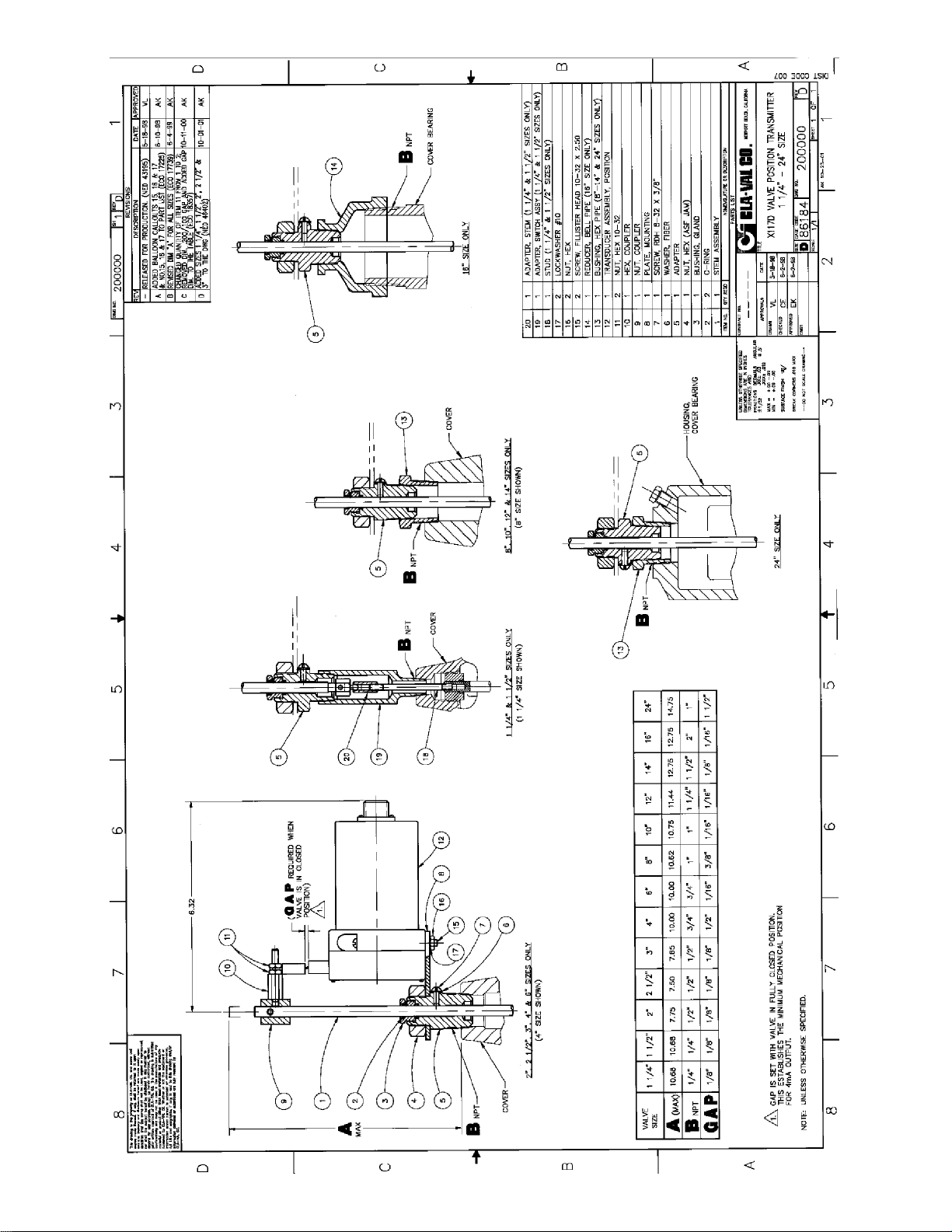
154
 Loading...