

Page 1
750B-4KG1
Page 2
Page 3
Page 4

Roll Seal
®
TM
750B - 4KG1
ROLL SEAL FIRE PUMP RELIEF VALVE
INTRODUCTORY INFORMATION
This manual is primarily intended for use as a manual for the UL listed and FM
approved Roll Seal 750B-4KG1 Fire Pump Relief Valves. Certain sections may contain
information that would be useful for the care installation and maintenance of other
Roll Seal products and Valve sizes. This extra data is intended as additional reference
information for the Roll Seal product line.
The product literature for the Roll Seal 750B - 4KG1 Fire Pump Relief Valve notes the
particular Valve Sizes and configurations that are UL listed or FM approved. Consult
the factory or your nearest sales representative if further clarification is required.
UL listed and FM approved products are identified by the appropriate nameplate on
the Valve. Drawings of the UL & FM nameplates are enclosed for reference.
The UL nameplate drawing number 86060. The FM nameplate drawing number is 94777.
This manual contains information regarding care, installation and maintenance of
the Roll Seal Main Valve (100-42) as well as information about the fully piloted product (750B-4KG1 Fire Pump Relief Valve). 100-42 is the identifying nomenclature for
the Main Valve. 750B-4KG1 is identifying nomenclature for the fully piloted Fire Pump
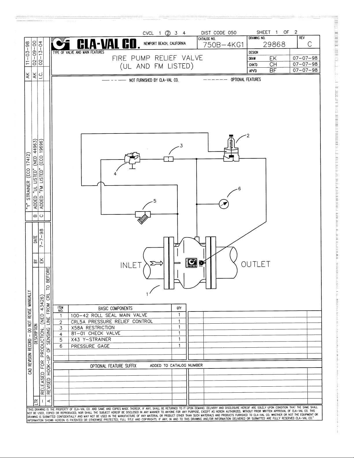
Relief Valve Assembly. See Schematic Drawing No. 29868 for clarification of the component nomenclature and for a description of Valve Operation.
A capacity flow curve for Valve sizes 3" through 10" is included that shows the flow
capacity in the full open valve condition.
Cla-Val recommends that 750B-4KG1 Valves be tested after installation to verify the
Relief pressure set point.
Page 5

2
3
4
5
6
1
INLET
OUTLET
750B-4KG1 Basic Components
Fire Protection Pressure Relief Valve
750B-4KG1
Description
The Cla-Val Model 750B-4KG1 Pressure Relief Valve is a hydraulically
operated pilot actuated automatic control valve designed specifically to
automatically relieve excess pressure in fire protection pumping systems.
Pilot co ntrol led, it maintains consta nt system pressure at the
pump discharge within very close limits as demands change. The main
valve consists of a stainless steel body and only one moving part, an
elastomeric liner or control element.
Cla-Val Model 750B-4KG1 will control from no flow, to full open flow, without any chattering or slamming. For this reason, there is never a region
of control instability. There is no slip-type friction because the valve has
no bearings. Cla-Val Model 750B-4KG1 valves have excellent resistance to cavitation with a Cffactor of 0.9.
Pilot controls are fully piped at the factory and the Cla-Val Model 750B-4KG1
is shipped complete, ready for installation.
Material Specification
Body: 316L Stainless Steel
Liner: Nitrile, 70 durometer
Liner Retainer: 316 Stainless Steel
Pilot
Body: ASTM B62 Bronze*
Spring Cover: ASTM B62 Bronze*
Wetted Parts: Bronze/Stainless Steel*
Buna-N
®
Accessories
Check Control: Brass*
Control Piping: Copper*
“Y” Strainer: Bronze*
Control Fittings: Brass*
*
316 stainless steel available
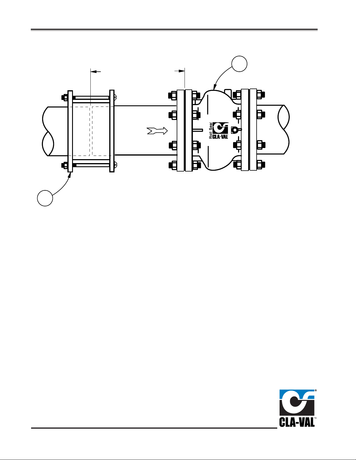
Item Description
1 100-42 Roll Seal Main Valve
2 CRL5A Pressure Relief Control
3 X58A Restriction
4 81-01 Check Valve (125 psid max. reverse pressure)
5 X43 Y-Strainer
6 Pressure Gauge
FM
PENDING
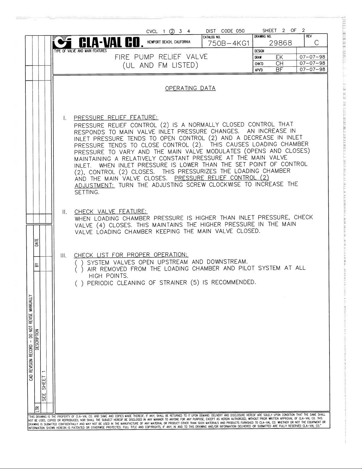
At pump start, the Cla-Val Pressure Relief Valve modulates
to relieve excess pump capacity, maintaining positive system pressure at the pump discharge.
When fire demand slows or ceases, the main valve opens,
diverting the entire pump output to discharge, allowing the
fire pump to be stopped without causing surging in the lines.
(Please note that when the Model 750B-4KG1 is to be used
on a continuous duty basis to maintain fire-system pressure,
suitable back pressure must be provided on the valve to prevent cavitation damage. Consult the factory for details.)
Operation Sequence
MODEL
For Seawater Service Options See 750-20 E-sheet
For other than standard ANSI flanges consult factory
Din drilling available on all sizes
Page 6

C
LA-VAL
PO Box 1325 Newport Beach CA 92659-0325 Phone: 949-722-4800
Fax: 949-548-5441
Web Site: cla-val.com E-mail: claval@cla-val.com
CLA-VAL CANADA CLA-VAL EUROPE
4687 Christie Drive
Beamsville, Ontario
Canada LOR 1B4
Phone: 905-563-4963
Fax: 905-563-4040
E-Mail: sales@cla-val.ca
Chemin des M
é
sanges 1
CH-1032 Romanel/
Lausanne, Switzerland
Phone: 41-21-643-15-55
Fax: 41-21-643-15-50
E-Mail: cla-val@cla-val.ch
Copyright
CLA-VAL 2005 Printed in USA Specifications subject to change without notice.
CLA-VAL UK
Dainton House, Goods Station Road
GB - Tunbridge Wells
Kent TN1 2 DH England
Phone: 44-1892-514-400
Fax: 44-1892-543-423
E-Mail: info@cla-val.co.uk
©
E-750B-4KG1 (R-8/06)
Represented By:
When Ordering
Please Specify
1. Catalog No. 750B-4KG1
2. Valve Size
3. Fluid Being Handled
4. Fluid Temperature Range
5. Inlet Pressure Range
Purchase Specification
The Fire Pump Pressure Relief Valve shall modulate to relieve
excess pressure in a fire protection system. It shall maintain
constant pressure in the system regardless of demand changes.
It shall be pilot controlled and back pressure shall not affect its set
point. It shall be actuated by line pressure through a pilot control
system and open fast in order to maintain steady system pressure
as system demand decreases. It shall close gradually to control
surges and shall re-seat drip-tight within 5% of its pressure setting. This valve shall be UL Listed and Factory Mutual approved.
The control valve shall be constructed of a 316L stainless steel
body and only one moving part, an elastomeric liner or control
element. Minimum rangeability shall be 500:1 based on capacity
at flowing pressure conditions. Cf shall be greater than or equal
to 0.9. Valve and control system shall be similar in all respects to
Cla-Val Model 750B-4KG1 as manufactured by Cla-Val, Newport
Beach, California.
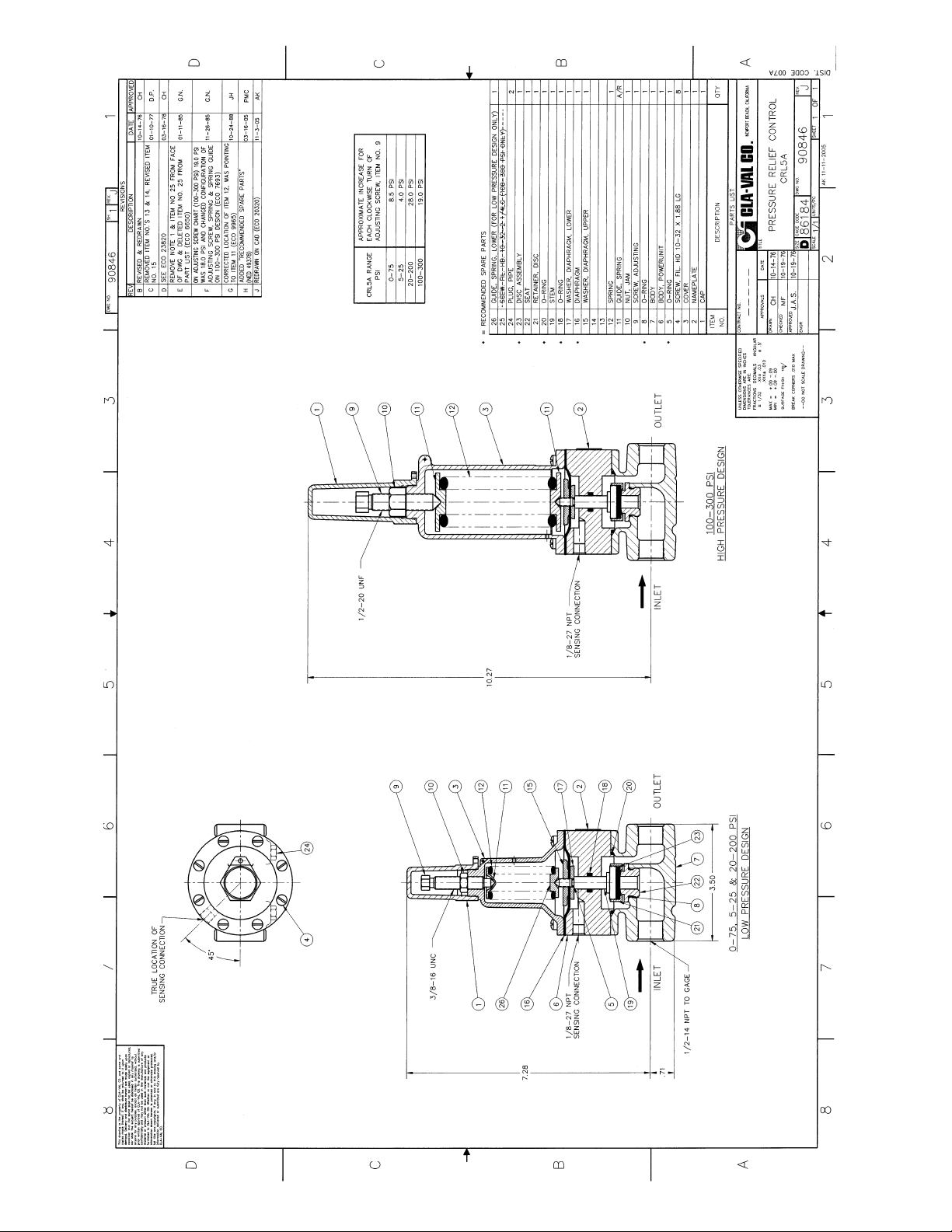
3/8" N.P.T.
3 PORTS
"A" TYP.
"BB"
DIA.
FLOW
"CC"
2", 3", 4" and 6" Wafer Style
"E" N.P.T.
"E" N.P.T.
"E" N.P.T.
"D"
DIA.
"B"
DIA.
"C"
6", 8",10" and 12" Flanged Style
Dimensions (100-42 Main Valve)
Performance Specification
Capacity: See Technical Data Sheet
CfFactor: 0.9
Cavitation: See Technical Data Sheet
Rangeability: 500:1
Bearing Friction: No friction from slip-type
bearings
Design Specification
Sizes: 2, 3, and 6 inch wafer style
6, 8, 10, and 12 inch flanged
End Detail Wafer: Fits ANSI B16.5 class 125,150,
250, and 300 flanges
End Detail Flanged: ANSI B16.5 class 150
(fits class 125) or
ANSI B16.5 class 300
(fits class 250)
Maximum Relief Pressure: 3" thru 10" 150 lb. class - 200 psi
3" thru 10" 300 lb. class - 300 psi
Approvals: U.L. Listed.........Sizes 3" thru 10"
FM Approved....Sizes 3" and 4"
Not UL or FM.... Sizes 2" and 12"
Maximum Differential: 150 psid continuous,
225 psid intermittent*
Reverse Pressure
: 125 psid maximum
Temperature Range: 32 to 160 degrees F*
Flange Operating Pressure: Class 125-175 psi maximum
Class 150-275 psi maximum
Class 250-300 psi maximum
Class 300-720 psi maximum
*Temperature range depends on liner material. Higher differential pressure
ratings available.
6. Outlet Pressure Range
7. Maximum Differential Pressure
8. Minimum Differential Pressure
9. Maximum Flow Rate
10. Pilot Set Point
Valve Size (Inches) 2 3 4 6 8 10 12
A 27Ú8 39Ú16 41Ú8 51Ú4 -- -- --
B -- -- -- 107Ú8 143Ú8 18 215Ú8
BB 43Ú8 57Ú8 73Ú8 913Ú16 -- -- --
C -- -- -- 9 11 13 151Ú4
CC 21Ú2 31Ú4 4 51Ú2 -- -- --
D (ANSI 150) -- -- -- 11 131Ú2 16 19
D (ANSI 300) -- -- -- 121Ú2 15 171Ú2 201Ú2
E (Ports) NPT -- -- --
3
Ú8
3
Ú8
1
Ú2
1
Ú2
Approx. Wt. (150 lbs.) 4 71Ú2 14 58 115 190 290
Approx. Wt. (300 lbs.) 4 71Ú2 14 87 155 250 375
Max. Continuous Flow (gpm) 224 469 794 1787 3177 4964 7148
Valve Size (mm for ANSI) 50 80 100 150 200 250 300
A 73 90 105 133 -- -- -B -- -- -- 276 356 457 549
BB 111 149 187 249 -- -- -C -- -- -- 229 279 330 387
CC 64 83 102 140 -- -- -D (ANSI 150) -- -- -- 279 343 406 483
D (ANSI 300) -- -- -- 318 381 445 521
E (Ports) NPT -- -- --
3
Ú8
3
Ú8
1
Ú2
1
Ú2
Approx. kg. (150 lbs.) 1.81 3.63 6.35 30 54.43 89 151.5
Approx. kg. (150 lbs.)with Studs & Nuts 2.72 4.54 10 -- -- -- -Approx. kg. (300 lbs.) 1.81 3.63 6.35 41.73 72.57 116.57 191
Approx. kg. (300 lbs.)with Studs & Nuts 5 6.35 11.8 -- -- -- --
Max. Continuous Flow (l/s.) 14 30 50 113 200 301 451
Page 7

INSTALLATION / OPERATION / MAINTENANCE
Model 100-42 Valve
in Closed Position
Upstream pressure is introduced to the
control chamber (the chamber formed
behind the liner) through the control
piping and restrictor. When the pilot is
closed, full inlet pressure is supplied to
the control chamber, thus balancing the
force developed by inlet pressure acting on the upstream face on the liner.
Under these conditions, the liner
remains in the fully closed position.
Since the operating pressure in the
control chamber is greater than the outlet pressure, an additional closing force
is developed across the liner, pressing
the liner against the surrounding slotted
grillwork area and seating surface.
Model 100-42 Valve
in Partially Open Position
As loading pressure is lowered slightly
below inlet pressure, the central portion
of the liner is forced to invert and come
to rest against the tip of the control
chamber cavity. Reducing the loading
pressure further (but still higher than
outlet pressure) causes the liner to
drape over the cone shaped portion of
the control chamber cavity. This action
causes the outer section of the liner to
roll off the seating surface and a portion
of the grillwork to partially open the
valve.
Model 100-42 Valve
in Fully Open Position
The valve is fully opened when loading
pressure is sufficiently reduced to allow
the liner to roll back completely and
expose the full slot area. Restoring
loading pressure reverses the liner
rolling action to return the liner to the
fully closed position.
DESCRIPTION
PRINCIPLE OF OPERATION
PILOT
CONTROL
VALVE
RESTRICTOR
SEATING AREA
CONTROL CHAMBER
INLET
Pilot
Control
Valve
RESTRICTOR
SEATING AREA
CONTROL CHAMBER
INLET
PILOT
CONTROL
VALVE
RESTRICTOR
SEATING AREA
INLET
CONTROL CHAMBER
100-42
The Cla-Val Model 100-42 Roll Seal valve
is a hydraulically operated valve used to
control liquid flow by means of a flexible
control element, the liner.
The basic valve consists of only two parts:
a one piece, investment cast body and an
elastomeric liner. The valve body is constructed with internal ribs and slots forming
a grillwork which surrounds the liner to provide support. A normally closed type valve
is formed by the installed liner which covers
the grillwork and seats against the raised
seating surface in the valve body.
Upstream pressure actuates the valve to
produce valve opening by rolling the liner off
the seating surface and the slotted grillwork.
The valve is actuated by upstream pressure
as the loading pressure (pressure supplied
to the control chamber) is varied by an
external pilot control system.
A typical pilot control system used to operate the Model 100-42 valve consists of a
restriction and a suitable pilot connected to
the valve.
700 Series Roll Seal
SERIES
Page 8
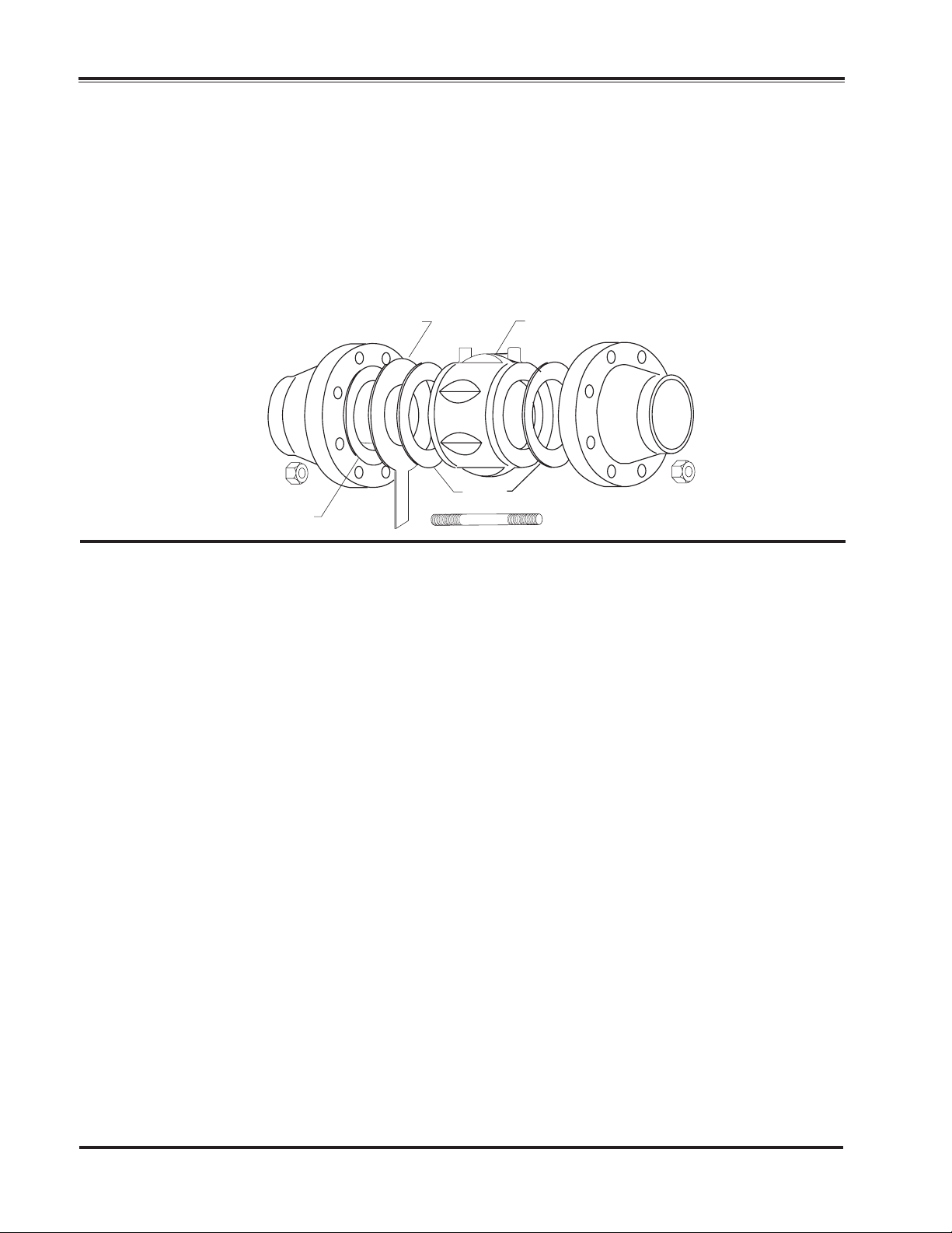
The Model 100-42 valve in 6" through
12" sizes are constructed with separable "slip-on" style flanges. Furnished
standard in either class 150 or 300
raised face type, the flanges are
removable and interchangeable. The
class 150 flange may be bolted up to
class 125 pipeline flanges and the
class 300 flange may be mated
against a class 250 flange.
Locate pilot system port connections
at the top of valve in pipeline to allow
easy air venting. A line size strainer is
recommended, mounted on the valve
inlet.
The valve should be given a visual inspection before installation to be sure no foreign
materials have collected inside the valve
during shipment or storage.
Pipelines should be flushed out before the
valve is installed in the system. New systems, especially, should be cleaned as contaminates such as welding beads, scale,
rocks, etc. are commonly contained within
the pipeline.
The valve should be installed in a location
allowing sufficient working space around
the valve to provide easy access for maintenance and removal for servicing.
For 2", 3", and 4" sizes only. Insert the lower
half pattern of stud bolts through the bolt
holes of the upstream and downstream
pipeline flanges.
For 2" & 3" valves only. The 125 and 150
series flanges use a different number of
bolts than the 250 and 300 series flanges.
Hence, the wafer valve body configuration
is inherently self centering regardless of the
flange used.
Install the valve between the flanges being
sure to include the appropriate flange gaskets between each end of the valve and the
mating pipe flange.
Note: The valve must be installed with the
flow arrow on side of body pointing to the
downstream piping section. Cla-Val 700
Series valves may be installed in any position in either vertical or horizontal installations without any effect on valve operation.
Insert the remaining stud bolts and nuts and
tighten evenly using a diagonal cross-over
type pattern.
For the 4'' valve, ANSI pipe flanges use an
8 bolt pattern regardless of pressure ratings, although the 250 and 300 series use
larger bolts on a larger bolt circle. The 4"
valve can be centered in the larger 250 and
300 class flanges by rotating the valve body
into full radial contact with the bolt studs
prior to tightening.
INSTALLATION
PROCEDURE
2.
3.
4.
4a.
6.
7.
1.
Gasket
Gasket
Recommended Strainer
Model 100-42 Roll Seal Valve
The Cla-Val Model 100-42 Roll Seal
valve in 2", 3", and 4" sizes are
designed to mount between standard
pipe flanges (ANSI 125, 150, 250, and
300 series) as a wafer type valve. The
outer portion of the valve body is constructed with fluted (recessed) sections to provide clearance for the class
125 and 150 flange bolt pattern while
the basic outside diameter of the body
centers within the class 250 and 300
flange bolt pattern.
If an inline basket type strainer is to be
included in the installation, insert the strainer into the upstream pipe, making sure a
gasket is placed between the strainer and
the upstream flange.
4b.
5.
Page 9

Liner Retainer Removal 2"-12" Sizes
1
3
5
7
9
2
4
6
8
10
The 2" and 3" liner retainer is secured to the valve with an Allen
screw. Loosen the Allen screw, pull the locking pin back towards
center of retainer, and remove the retainer from valve.
To install, insert the retainer, (do not block inlet feed hole), push
locking pin into position and tighten Allen screw.
The 4"-12" liner retainers are secured with a snap ring. Remove
the snap ring and retainer.
To install, insert retainer and install snap ring into the groove of
valve. Be sure snap ring is completely inserted into groove.
Liner Removal 2"-12" Sizes
The tool used for removal should be free of sharp edges to prevent damage to the liner, the valve body seat or control chamber surfaces. A motorcycle tire iron or similar tool works well.
1. Insert the tool between the liner and the valve body as
deeply as possible.
2. Using the seat edge as a fulcrum, rock the end of the tool
away from the valve in a manner to pull the liner bead out of the
body. Grasp the liner and remove from the valve body.
Liner Installation 2", 3", 4" Sizes
Thoroughly clean out the interior of the valve body control chamber cavity.
Liberally apply glycerine inside the control chamber cavity and
around the seal bead area of the liner.
DO NOT USE ANY HYDROCARBON OR SILICONE BASED
LUBRICANTS ON LINERS AS THESE COMPOUNDS CAN
SEVERELY ATTACK THE LINER MATERIAL.
3. Fold the liner as shown and install into the valve body control chamber as deeply as possible.
4. Continuing to force the liner into the control chamber cavity,
again fold the liner as shown to insert the liner seal bead section
under the valve body seat surface.
5. Work the folded section of the liner into place by pushing
against the folded area to slide the seal bead down the conical
face of the control chamber.
Liner Seating Instructions 2", 3", 4" Sizes
After installing the liner, it must be seated over the manifold ring
in the valve body. The objective of this seating procedure is to
place the inside lip of the liner over the outside lip of the manifold ring.
6. 4" valve with liner installed.
7. Pinch, pull and knead the liner 360° around to seat the liner
on the manifold ring.
8. Using a dull tool or hammer handle, pry the outer part of the
liner towards the center to help "seat" the liner.
9. Now push the liner down into the valve, holding your hand
on the depressed liner, seal off the loading port with your finger.
10. Remove your hand from liner and continue holding your finger over the loading port. If liner is seated, it will be held in the
open position as long as your finger is over the loading port.
When you release your finger, the liner will popup. If not seated,
repeat with Step 7.
Install liner retainer into body.
Page 10

Liner Installation
1
3
5
7
9
2
4
6
8
10
6", 8", 10", 12" sizes
1. Tools required: Bottle of drugstore glycerine,
30" crowbar, double headed plastic hammer
with 14" handle, rubber mallet and large flat
blade screwdriver.
2. Liberally wipe glycerine on the inside of the
valve and on the outer edge of the liner. Fold
liner in half and insert into valve body.
3. Push liner in as far as possible forcing it out side
ways.
4. Place the crowbar at the upper 25% point of the
liner. Take your other hand and push on nose of liner
to bend the liner over the crowbar. The less material
folded over, the easier it will go into the valve. If too
much is folded over, it will be difficult to complete
liner installation.
5. Continue bending liner nose down into the valve.
Use your hands and/or hammer handle to continue
forcing it down into valve. It is important to keep the
"V" of the bend near the 25% point. If it goes over
the center, The liner won't go in, and it will be necessary to start over at Step 3.
6. Use the hammer to force the liner down and out into
the valve body.
7. Use the hammer handle for the final insertion.
Sometimes it is helpful to beat on the liner with the
hammer for the final step.
8. To seat the liner on the manifold ring use the hammer handle to push down on the liner near bore of
valve inlet and pry handle and liner towards the center. Continue this prying action for 360° around the
liner for proper seating.
9. To test for liner seating, push down on the center of
liner and close the loading port shut-off cock, or
block it with your hand. When you release your hand
from the liner, it should remain in the down position
until the loading port is opened.
10. If liner appears seated, open loading port cock and
liner should pop-up to the closed position. Repeat
Steps 6-10 if liner is not seated.
When the liner is fully seated, the inside diameter of
the liner will be seated over the outside diameter of
the manifold ring. The manifold ring is a raised circular ridge at the bottom of the open cavity which provides for even distribution of the fluid coming in and
going out the loading port.
Install liner retainer into body.
Page 11
PLACING VALVE INTO OPERATION
In most instances, the 700 Series Cla-Val
Control valves will be shipped complete
with a pilot control system mounted on the
Model 100-42 valve. Consult the appropriate start up and operation instructions for
the pilot control used before pressurizing
the system.
START-UP INSTRUCTIONS
Pressure Reducing
790 Series Valves
Important Procedure for All Installations:
IT IS IMPORTANT THAT THE PRESSURIZATION AND DEPRESSURIZATION OF ALL
INSTALLATIONS BE CARRIED OUT IN A MANNER TO PREVENT IMPOSING A REVERSE
PRESSURE CONDITION ON THE CLA-VAL
MODEL 100-42 VALVE. PRESSURIZATION OF
THE SYSTEM SHOULD BE ACCOMPLISHED
BY PRESSURIZING THE INLET SIDE FIRST.
Back Pressure Control
750 Series Valves
DEPRESSURIZATION OF THE SYSTEM SHOULD BE ACCOMPLISHED BY
DEPRESSURIZING THE OUTLET SIDE
FIRST. FAILURE TO FOLLOW THIS
PROCEDURE COULD RESULT IN DISLODGEMENT AND/OR DESTRUCTION
OF THE RUBBER LINER.
Relief Valve Applications 750
Series Valves
The following instructions are for
valves equipped with a Model CRD
Pressure Reducing Pilot Control.
1.
Remove the adjustment cap and back
off adjustment screw setting (turn
counterclockwise) of the CRD
Pressure Reducing Pilot Control to fully
relieve all loading on the range spring.
Slowly open the upstream main line
2.
block valve to pressurize the inlet section of the valve.
3.
Bleed any entrapped air from the control chamber of the valve and tubing
sections by loosening fittings at the
highest points. Retighten fittings.
Install gauge on downstream port of
CRD.
4.
Slowly increase tension on the range
spring, by means of the adjustment
screw (turn clockwise) until the desired
downstream pressure is attained. Use
a gauge.
5.
Open the downstream main line block
valve.
If required, reset the pilot adjustment
6.
screw setting to obtain the downstream
pressure desired.
7.
Tighten the adjustment screw lock nut
and replace the adjustment cap.
The following instructions are for
valves equipped with a Model CRL
Back Pressure Pilot Control.
1.
Remove the adjustment cap and
increase tension on the range spring,
by means of the adjustment screw
(turn clockwise) until maximum
spring load is attained.
2.
Slowly open the upstream main line
block valve to pressurize the inlet
section of the valve.
Bleed any entrapped air from the
3.
control chamber of the valve and tubing sections by loosening fittings at
the highest points. Retighten fittings.
4.
Open the downstream main line
block valve.
5.
Gradually decrease tension on the
range spring by means of the adjustment screw (turn counterclockwise)
until upstream pressure decreases to
the desired setpoint.
6.
Tighten the adjustment screw lock
nut and replace the adjustment cap.
The following instructions are for valves
equipped with a Model CRL Pressure
Relief Pilot Control.
Due to the nature of intended use, the
system being protected with the relief
valve will most likely not be able to furnish the pressure source needed to
establish the proper setpoint of the pilot
control. Due to this fact, in most
instances, the relief valve setting procedures will either have to be carried out at
other locations or an auxiliary pressure
source will have to be supplied at the
site in order to carry out the following
procedure.
1.
Remove the adjustment cap and
increase tension on the range spring by
means of the adjustment screw (turn
clockwise) until maximum spring load is
attained.
2.
Slowly introduce inlet pressure to the
valve at the desired setpoint value.
Bleed all air.
3.
Gradually decrease tension on the
range spring by means of the adjustment screw (turn counterclockwise) until
flow is initiated through the valve.
4.
Reduce system pressure back to normal
value. Tighten the adjustment screw
lock nut and replace the adjustment cap.
The valve is now ready for service.
Taking Valve Out of Service
The following procedure should be followed
when taking the Model 100-42 valve out of
service.
1.
Close the upstream main line block valve
first. Then close the downstream main line
block valve.
2.
Vent the downstream section to fully relieve
pressure in the outlet section of the valve.
Vent the upstream section to fully relieve
3.
pressure in the inlet section and control chamber of the Model 100-42 valve.
If the valve liner is to be inspected or
4.
replaced, remove the valve from the main line.
Page 12
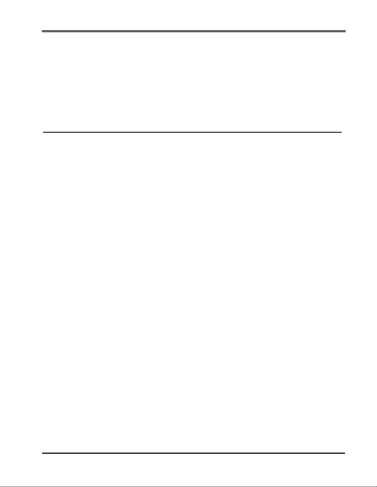
2
T
Recommended Pipe layout
6" - 12" Flange style 100-42
2 Pipe Coupling (Rubber Gasket Type)
1 100-42 Main Valve, Flange X Flange
2 1/2 Pipe Diameters
1
Min Recomended
Length Spool
OUTLE
Page 13

2 1/2 PIPE DIAMETERS
MIN RECOMENDED
LENGTH SPOOL
INLET
INLET
®
™
Roll Seal
3
®
™
Roll Seal
4
OUTLET
OUTLET
2
1
Recommended Pipe layout
6" - 12" Grooved style 100-42
1 COUPLER FOR GROOVED PIPE
2 SPOOL STRAINER ASSEMBLY (WITH CONE)
3 100-42 MAIN VALVE, GROOVE X FLANGE
4 100-42 MAIN VALVE, GROOVE X GROOVE
Page 14

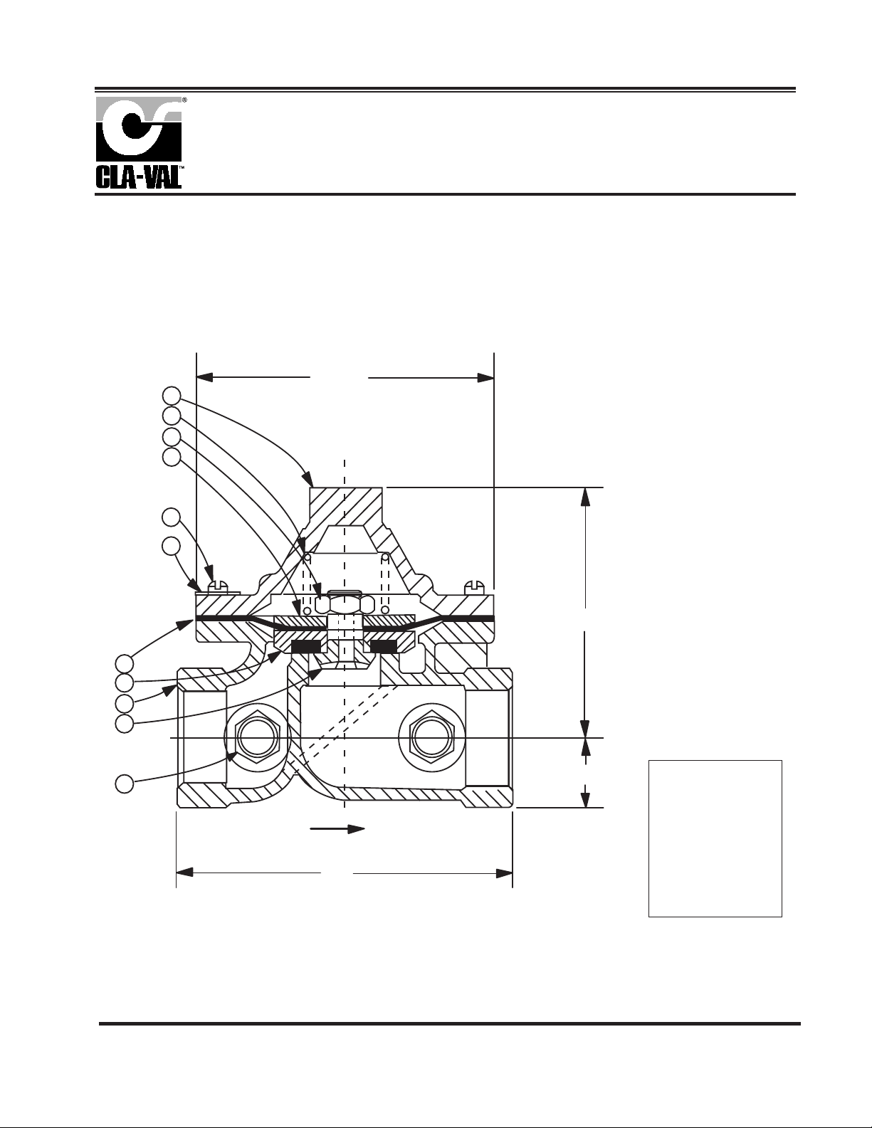
1
When ordering
please specify:
• All nameplate data
• Description
• Part Numbers
• Item Number
• Material
CLA-VAL
Copyright Cla-Val 2008 Printed in USA Specifications subject to change without notice.
P.O. Box 1325 • Newport Beach, CA 92659-0325 • Phone: 949-722-4800 • Fax: 949-548-5441 • E-mail: claval@cla-val.com • Website cla-val.com
©
N-100-42 (R-1/08)
Item
No.
Description
No.
Req'd
Material
(Standard)
1
2*
3
4
5
6
7
8
Body
Liner
Nameplate
Drive Screw
Liner Retainer
Retaining Ring
Slip-on Flange
Flange Retainer Ring
*Recommended Spare Part
5
1
1
1
2
1
1
2
2
1
7
8
316L Stainless Steel "L"
Natural Rubber
Aluminum
316L Stainless Steel
316L Stainless Steel
316L Stainless Steel
Steel-Cad. Pl.
Steel-Cad. Pl.
2
6
5
4
3
5
6
4
3
2
4" Wafer Style Valve 2-3" Wafer Style Valve 6"-12" Flanged Valve
Page 15
Page 16

Capacity Information
700 Series
MODEL
1
1
However, the above stated relationship only remains valid if the flowing conditions are both turbulent
(non-viscous) and non-cavitating. Fortunately, these conditions are the most common encountered in
liquid flow applications. In those cases where viscous or cavitating
(1)
flow conditions are possible,
consult factory for guidance in selection of valve size.
Example:
Determine the maximum flow rate capability of a 4" Cla-Val Roll Seal valve in fresh water service with
an upstream pressure of 90 psi and downstream pressure of 77 psi. From table, a 4" Cla-Val 700
Series valve has a full open C
v
factor of 128; hence:
Valve Sizing Coefficient - Cv
A very useful expression often used in determining the head loss and/or flow rate capacity of control
valves is the Cvfactor. Commonly referred to as the flow coefficient or valve sizing coefficient, this
empirically determined factor describes the flow capacity of a valve.
The C
v
factor is defined as the number of U.S. gallons per minute of water (at 60°F flowing temperature)
discharged through a flow restriction with a head loss of one psi. In the case of a control valve, the C
v
value is normally stated for the valve in the fully open position. For conditions other than full open, (i.e.
modulating valves), contact Cla-Val Technical Services.
Cla-Val 700 Series Valves - Full Open C
v Factors
Liquid Flow Equation
The basic flow to pressure drop relationship for liquid service is expressed by the formula:
Q = 128 = 128 (3.61) = 462 GPMx
13
or
Q = Flow rate in U.S. gallons per minute (GPM).
C
v
= Valve sizing coefficient.
∆P = Head loss across valve in psi.
G = Specific gravity of liquid at flowing temperature referred to
water (1.0) at standard conditions (60°F).
Where:
(1) Note: For further information on cavitation, see technical data sheet "RS-Cavitation".
Q = C
v
Q = C
v
x
∆P
G
∆P
or
1
G
Valve Size 2" 3" 4" 6" 8" 10" 12"
Cv Factor
48 84 128 451 764 1443 2048
Page 17

N-RS-Capacity (R-8/00)
Specific Gravity Correction Table
Maximum Continuous Flow (U.S. GPM)
Specific
Gravity
"G"
Correction
Factor 1
G
0.75 0.80 0.85 0.90 0.95 1.00 1.05 1.10 1.15 1.20 1.30 1.40
1.15 1.12 1.08 1.05 1.03 1.00 0.98 0.95 0.93 0.91 0.88 0.85
To obtain flow capacity of a liquid other than water (specific gravity of 1.00), multiply water flow capacity obtained by the
appropriate specific gravity correction factor.
NOTE: The flow rate vs. head loss data presented here is based on a fully open valve condition. The maximum
recommended velocity is 20 ft./sec.
Valve Size
Maximum
Continuous
Flow
2" 3" 4" 6" 8" 10" 12"
224 469 794 1787 3177 4964 7148
3"
4"
10000100010010
1
10
100
2" THRU 12" ROLL SEAL FLOW CURVES
STANDARD VERSION WITH LINER RETAINER
(COVER TO ATMOSPHERE)
FLOW (GPM)
PRESSURE DROP (PSI)
10"8"6"
2"
12"
Page 18

*This drawing is the property of CLA-VAL and same and copies made thereof, if any, shall be returned to it upon demand. Delivery and disclosure hereof are made solely
upon condition that the same shall not be used, copied ore reproduced, nor shall the subject here of be disclosed in any manner to anyone for any purpose, except as
herein authorized, without prior approval of CLA-VAL. Whether or not the equipment or information shown hereon is patented or otherwise protected, full title and copyrights if any, in and to this drawing and/or information delivered or submitted are fully reserved by CLA-VAL.
Dwg#47117
Regulator Spring Color Coding Chart
THE FOLLOWING CONTROL & SPRING P/N#'S WERE REMOVED, 32656B, 31554K, 44591G, V65695B, & V5695B.
ADDED CRL-13, CRL-5A, CRA, CRA-10A, CHANGED SPRING RANGES TO MATCH CURRENT CONTROLS.
CLA-VAL
Copyright Cla-Val 2008 Printed in USA Specifications subject to change without notice.
P.O. Box 1325 • Newport Beach, CA 92659-0325 • Phone: 949-722-4800 • Fax: 949-548-5441 • E-mail: claval@cla-val.com • Website cla-val.com
©
PL-47117 AF (R-1/08)
PARTS LIST
WIRE SIZE SPRING NUMBER COLOR WIRE MATERIAL CATALOG NUMBER PSI RANGE *PSI PER TURN
.080 DIA. C0492D BLUE S.S.
CDB-7
CRL-5A
0-7
0-7
.75
.75
.018 DIA. 82575C -- S.S.
CRD
CRD-10A
1.9-6.5
1.9-6.5
.61
.49
.116 DIA. 81594E -- S.S.
CRD
CRD-10A
2-30
2-30
3.0
2.4
.120 DIA. V5654J GREEN CHR VAN
CRL-5A
CRD
5-25
10-40
4.0
4.0
.162 DIA. 32447F NATURAL S.S.
CDB-7
CRL-5A
CRL-13
10-60
10-60
10-60
12.0
12.0
12.0
.162 DIA. V5695B YELLOW MUSIC WIRE
CDB-7
CRL-5A
CRL-13
20-80
20-80
20-80
14.5
14.5
14.5
.207 DIA. C1124B CAD PLT MUSIC WIRE
CDB-7
CRL-13
CRL-5A
50-150
50-150
50-150
29.5
29.5
29.5
.225 DIA. V6515A RED MUSIC WIRE
CDB-7
CRL-13
CRL-5A
65-180
65-180
65-180
44.0
44.0
44.0
.115 X .218 71884B RED CHR VAN
CRL
CRD
CRD-10A
0-75
15-75
15-75
8.5
9.0
7.2
.118 X .225 71885J GREEN CHR VAN
CRL
CRD
CRD-10A
20-200
30-300
30-300
28.0
27.0
22.4
.225 X .295 1630201A CAD PLT CHR VAN
CRL
CRL-5A
100-300
100-300
18.00
18.00
.440 X .219 48211H CAD PLT STEEL
CRA-18
CRD-22
CRL-4A
200-450
200-450
100-450
17.0
17.0
17.0
.187 20632101E BLACK 316 SST
CRD
CRL
20-105
20-105
13.0
13.0
WIRE SIZE SPRING NUMBER COLOR WIRE MATERIAL CATALOG NUMBER PSI RANGE *FEET PER TURN
.080 DIA. C0492D BLUE S.S.
CRA
CRD-2
4.5-15
4.5-15
.82
.82
.375 DIA.
87719B
1 SPRING
2 SPRING
3 SPRING
4 SPRING
5 SPRING
EPOXY
COATED
CHROME SILICON CDS-5
5-40
30-80
70-120
110-120
150-200
1.0
2.0
3.0
4.0
5.0
.072 DIA. V5097A -- 302SS CVC 1-17 .7
.375 DIA.
2933502H
1 SPRING
2 SPRING
3 SPRING
4 SPRING
5 SPRING
EPOXY
COATED
CHROME SILICON CDS-6A
5-40
30-80
70-120
110-160
150-200
.75
1.50
2.20
3.00
3.70
*THESE FIGURES ARE ONLY APPROXIMATE. FINAL ADJUSTMENTS SHOULD BE MADE WITH A PRESSURE GAGE.
Page 19

THREADED 3/8" 18 NPT
CLA-VAL
Copyright Cla-Val 2008 Printed in USA Specifications subject to change without notice.
P.O. Box 1325 • Newport Beach, CA 92659-0325 • Phone: 949-722-4800 • Fax: 949-548-5441 • E-mail: claval@cla-val.com • Website cla-val.com
©
PL-X58A (R-1/08)
PARTS LIST
(TYP. BOTH ENDS)
X58A
Restriction Pipe Fitting
"A" DIA.
When ordering parts,
please
specify:
• All Nameplate Data
.69
HEX
(Stock)
• Description
• Size
Part No. Material "A"
Orifice Dia.
74894-07C Brass 3/32" (.093)
74894-06E 303 SS 1/16" (.062)
74894-05G Brass 1/16" (.062)
74894-04K 303 SS 1/8" (.125)
74894-03B Brass 1/8" (.125)
Page 20

2.50
PARTS LIST
A
A
81-01
3/8" Check Valve
ITEM DESCRIPTION
1. Cover Screw (8 Required)
2. Cover
*3. Spring
4. Diaphragm Washer
*5. Diaphragm
*6. Disc Retainer Assembly
7. Body Plug (3/8 NPT)
8. Body (Threaded)
*Recommended Spare Parts
2
1.50
1.25
Outlet
3/8 N.P.T.
Flow
2.75
SECTION
AA
3/8 N.P.T.
BOTH ENDS
Inlet
3
1
4
5
6
When ordering
8
7
parts, please
specify:
• All nameplate data
• Description
• Part Number
• Item Number
• Material
Page 21
10
CLA-VAL
Copyright Cla-Val 2008 Printed in USA Specifications subject to change without notice.
P.O. Box 1325 • Newport Beach, CA 92659-0325 • Phone: 949-722-4800 • Fax: 949-548-5441 • E-mail: claval@cla-val.com • Website cla-val.com
©
PL-81-01 (R-1/08)
PARTS LIST
1. Body 1
2. Cover 1
*3. Diaphragm 1
4. Guide Disc 1
*5. Disc Retainer Assembly 1
7. Nut Hex 3/8 - 24UNF 28 1
8. Plug Pipe Hex NPT 2
9. Screw, Fil HD 10 32UNF 2 x 2LG 8
10. Spring 1
11. Nameplate 1
81-01
1/2" & 3/4 Check Valve
ITEM DESCRIPTION
3.12 DIA
2
7
6
9
*Recommended Spare Parts
11
2.56
3
5
1
4
OUTLETINLET
8
.56
When ordering
parts, please
specify:
FLOW
3.50
• All nameplate data
• Description
• Part Number
• Item Number
• Material
Page 22

ITEM DESCRIPTION MATERIAL
1 Pipe Plug Steel
2 Strainer Plug Brass
3 Gasket Copper
4 Screen SST
5 Body Brass
1
2
3
4
5
3/8 NPT
2.06
2.72
SIZE STOCK NUMBER
3/8 x 3/8 33450J
Strainer
X43
No parts available. Rreplacement assembly only.
Standard 60 mesh pilot system strainer for fluid service.
CLA-VAL
Copyright Cla-Val 2008 Printed in USA Specifications subject to change without notice.
P.O. Box 1325 • Newport Beach, CA 92659-0325 • Phone: 949-722-4800 • Fax: 949-548-5441 • E-mail: claval@cla-val.com • Website cla-val.com
©
PL- X43 (R-1/08)
PARTS LIST
Page 23

CLA-VAL
©
copyright Cla-Val 2004 Printed in USA Specifications subject to change without notice.
P.O. Box 1325 • Newport Beach, CA 92659-0325 • Phone: 949-722-4800 • Fax: 949-548-5441 • E-mail: claval@cla-val.com • Website cla-val.com
How to Order
Roll Seal
¤
TM
CLA-VAL
How To Order
There are many valves and controls manufactured by Cla-Val. that
are not listed due to the sheer volume. For information not listed,
please contact your local Cla-Val
representative.
Specify when
ordering
• Model Number
• Adjustment Range
(As Applicable)
• Valve Size
• Optional Features
• Pressure Class
Unless Otherwise
Specified
• X43 “Y” Strainer is
included.
• CK2 Isolation Valves is
included in price on 6" and
larger valve sizes.
Limited Warranty
Automatic valves and controls as manufactured by Cla-Val are
warranted for one year from date of shipment against manufacturing defects in material and workmanship which develop in the
service for which they are designed, provided the products are
installed and used in accordance with all applicable instructions and limitations issued by Cla-Val.
We will repair or replace defective material, free of charge, which
is returned to our factory, transportation charges prepaid, provided that, after inspection, the material is found to have been
defective at time of shipment. This warranty is expressly conditioned on the purchaser’s giving Cla-Val immediate written
notice upon discovery of the defect.
Components used by Cla-Val but manufactured by others, are
warranted only to the extent of that manufacturer’s guarantee.
This warranty shall not apply if the product has been altered or
repaired by others, and Cla-Val. shall make no allowance or
credit for such repairs or alterations unless authorized in writing
by Cla-Val.
750B-4KG1
Product Identification
Proper Identification
For ordering repair kits, replacement parts, or for
inquiries concerning valve operation it is important to
properly identify Cla-Val products already in service.
Include all nameplate data with your inquiry. Pertinent
product data includes valve function, size, material,
pressure rating, end details, type of pilot controls used
and control adjustment ranges.
Identification Plate
For product identification, cast in body markings are
supplemented by the identification plate illustrated on
this page. The plate is mounted in the most practical
position. It is extremely important that this identifi-
cation plate is not painted over, removed, or in any
other way rendered illegible.
N-750B-4KG1 P.I.D.
Terms Of Sale
ACCEPTANCE OF ORDERS
All orders are subject to acceptance by our main office at
Newport Beach, California.
CREDIT TERMS
Credit terms are net thirty (30) days from date of invoice.
PURCHASE ORDER FORMS
Orders submitted on customer’s own purchase order forms will be
accepted only with the express understanding that no statements,
clauses, or conditions contained in said order form will be binding
on the Seller if they in any way modify the Seller’s own terms and
conditions of sales.
PRODUCT CHANGES
The right is reserved to make changes in pattern, design or materials when deemed necessary, without prior notice.
PRICES
All prices are F.O.B. Newport Beach, California, unless expressly
stated otherwise on our acknowledgement of the order. Prices are
subject to change without notice. The prices at which any order is
accepted are subject to adjustment to the Seller’s price in effect at
the time of shipment. Prices do not include sales, excise, municipal,
state or any other Government taxes. Minimum order charge
$75.00.
RESPONSIBILITY
We will not be responsible for delays resulting from strikes, accidents, negligence of carriers, or other causes beyond our control.
Also, we will not be liable for any unauthorized product alterations
or charges accruing there from.
Page 24

Disclaimer Of Warranties And
Limitations Of Liability
The foregoing warranty is exclusive and in lieu of all other
warranties and representations, whether expressed,
implied, oral or written, including but not limited to any
implied warranties or merchantability or fitness for a particular purpose. All such other warranties and representations
are hereby cancelled.
Cla-Val shall not be liable for any incidental or consequential
loss, damage or expense arising directly or indirectly from
the use of the product. Cla-Val shall not be liable for any
damages or charges for labor or expense in making repairs
or adjustments to the product. Cla-Val shall not be liable for
any damages or charges sustained in the adaptation or use
of its engineering data and services. No representative of
Cla-Val may change any of the foregoing or assume any
additional liability or responsibility in connection with the
product. The liability of Cla-Val is limited to material replacements F.O.B. Newport Beach, California.
Risk
All goods are shipped at the risk of the purchaser after they have been
delivered by us to the carrier. Claims for error, shortages, etc., must be
made upon receipt of goods.
EXPORT SHIPMENTS
Export shipments are subject to an additional charge for export packing.
RETURNED GOODS
1. Customers must obtain written approval from Cla-Val prior to returning any material.
2. Cla-Val reserves the right to refuse the return of any products.
3. Products more than six (6) months old cannot be returned for credit.
4. Specially produced, non-standard models cannot be returned for
credit.
5. Rubber goods cannot be returned for credit, unless as part of an
unopened repair kit which is less than six months old.
6. Goods authorized for return are subject to a 35% ($75 minimum)
restocking charge and a service charge for inspection, reconditioning, replacement of rubber parts, retesting and repackaging as
required.
7. Authorized returned goods must be packaged and shipped prepaid to
Cla-Val., 1701 Placentia Avenue, Costa Mesa, California 92627-
4475.
N-750B-4KG1 P.I.D.
Page 25

®
INSTALLATION / OPERATION / MAINTENANCE
750B-4KG1
™
Repair Kits
Roll Seal
The Cla-Val 700 Series valve repair kit for the 750B-4KG1 is the only recommended spare part. The valve
series is highly reliable due to fewer parts to create problems.
Valve repair kits are recommended over individual liner sales. Kits offer all essentials for easy installation to
include: liner, lubricant, liner retainer hardware, and instructions.
REPAIR KIT PART NUMBERS:
2" 3" 4" 6" 8" 10" 12"
Natural Rubber
65 Durometer
EPDM
70 Durometer
Nitrile
70 Durometer
Silicone
70 Durometer
Viton
70 Durometer
Natural Rubber
65 Durometer
EPDM
70 Durometer
Nitrile
70 Durometer
Silicone
70 Durometer
Viton
70 Durometer
R2001501A R2001502A R2001503J R2001504G R2001505A R2001506A R2001507K
R2002201J R2002202G R2002203E R2002204C R2002205K R2002206H R2002207F
R2002301G R2002302E R2002303C R2002304A R2002305H R20012306F R2002307D
R2001401F R2001402D R2001403B R2001404K R2001405G R2001406E R2001407C
R2002101A R2002102J R22002103G R2002104E R2002105A R2002106K R2002107H
LINER PART NUMBERS:
2" 3" 4" 6" 8" 10" 12"
R940001 R940101 R940201 R940301 R940401 R940501 R940601
R940006 R940106 R940206 R940306 R940406 R940506 R940606
R940007 R940107 R940207 R940307 R940407 R940507 R940607
R940003 R940103 R940203 R940303 R940403 R940503 R940603
R940005 R940105 R940205 R940305 R940405 R940505 R940605
REPAIR KIT PART NUMBERS:
(FOR UL LISTED 750B-4KG1 VALVE ASSEMBLY
3" 4" 6" 8" 10"
Nitrile
70 Durometer
R2002302E R2002303C R2002304A R2002305H R20012306F
LINER PART NUMBERS:
(FOR UL LISTED 750B-4KG1 VALVE ASSEMBLY
Nitrile
70 Durometer
When ordering, please give complete nameplate data of the valve and/or control being repaired.
P.O. Box 1325 • Newport Beach, CA 92659-0325 • Phone: 949-722-4800 • Fax: 949-548-5441 • E-mail: claval@cla-val.com • Website cla-val.com
CLA-VAL
©copyright Cla-Val 2000 Printed in USA Specification subject to change without notice.
R940107 R940207 R940307 R940407 R940507
MINIMUM ORDER CHARGE APPLIES.
N-750B-4KG1 RSRK (R-11/99)
 Loading...