

Page 1
60-31
MODEL
(Full Internal Port)
660-31
(Reduced Internal Port)
Booster Pump Control Valve
• Simple Hydraulic Operation
• Low Head Loss
• Built-in Check Valve
• Proven Reliable Design
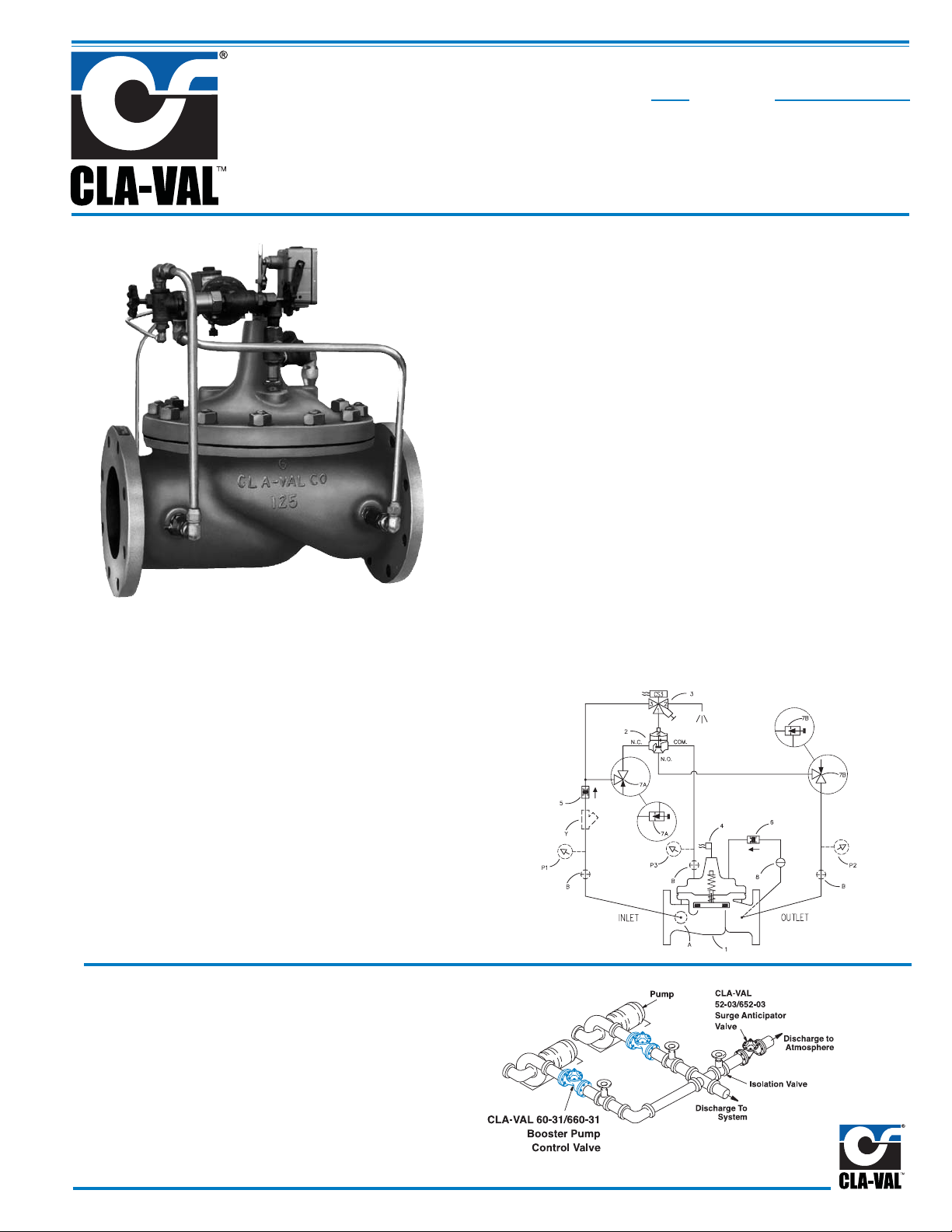
The Cla-Val Model 60-31/660-31 Booster Pump Control valve is a
pilot-operated valve designed for installation on the discharge of
booster pumps to eliminate pipeline surges caused by the starting
and stopping of the pump.
The pump starts against a closed valve. When the pump is started,
the solenoid control is energized and the valve begins to open
slowly, gradually increasing line pressure to full pumping head.
When the pump is signaled to shut-off, the solenoid control is deenergized and the valve begins to close slowly, gradually reducing
flow while the pump continues to run. When the valve is closed, a
limit switch assembly, which serves as an electrical interlock between the valve and the pump, releases the pump starter and the
pump stops.
Schematic Diagram
Item Description
1 Hycheck (Main Valve)
2 102C-3H Three Way Hytrol
3 CS3SM Solenoid Control
4 X10⁵LCW Switch Assembly
5 CDC Disk Check Valve
6 CDC/CSC Check Valve
7 CNA Angle Valve
8 CK2 Cock (Isolation Valve)
Item Description
A X46A Flow Clean Strainer
B CK2 Cock (Isolation Valve)
P X141 Pressure Gauge
Y X43 "Y" Strainer
Note: For main valve option descriptions, refer to the
100-04 (60-31) or 100-23 (660-31) Technical Data Sheet.
Typical Application
Install Model 60-31/660-31 valve as shown in multiple pump
applications. Flexible conduit should be used for electrical
connections to the solenoid control and the limit switch. A
Model 52-03/652-03 Surge
mended for power failure
Anticipator Valve is recom-
protection.
The Model 60-31/660-31 is an automatic valve of a modified globetype design with a built-in, lift type, check feature. It is hydraulically
operated and diaphragm-actuated. A three-way solenoid valve
controls the valve operation. Flow control valves located in the pilot
control system provide regulation of both the opening and closing
rate. Pilot system strainer insures that the pilot control supply is
clean.
Page 2
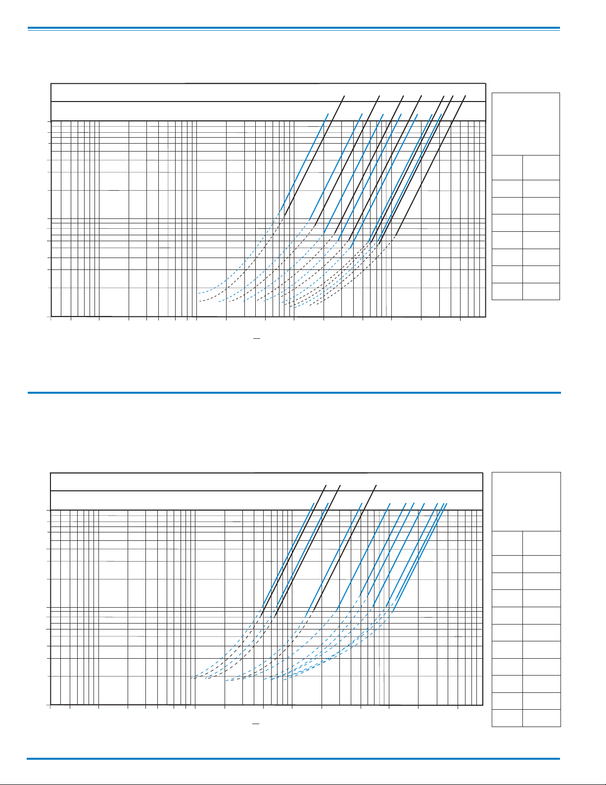
Model 60-31 Flow Chart (Uses Basic Valve Model 100-04)
Angle Valve Sizes (Inches)
Globe Valve Sizes (Inches)
100
80
60
40
30
psi
20
10
8
Pressure Drop —
6
46810
4
6
810
14
12
16
12
14
16
Cover Capacity
Liquid Volume Dis-
placed from Di-
aphragm Chamber
When Valve
Opens or Closes
Valve
Displace-
Size
ment
4” .17 gal
6” .53 gal
8” 1.26 gal
10” 2.51 gal
4
3
2
1
10 20 30 40 60 80 100 200 500 1000 2000 5000 10,000 20,000 50,000
53
Flow Rate gpm (water)
Model 660-31 Flow Chart (Uses Basic Valve Model 100-23)
Angle Valve Sizes (Inches)
Globe Valve Sizes (Inches)
100
80
60
40
30
20
68
4
6
4
12” 4.00 gal
14” 6.50 gal
16” 9.57 gal
Cover Capacity
Liquid Volume Dis-
8
14
10
12
24
20
16
18
placed from Di-
aphragm Chamber
When Valve
Opens or Closes
Valve
Displace-
Size
ment
4" .08 gal
6" .17 gal
10
8
Pressure Drop — psi
6
4
3
2
1
10 20 30 40 60 80 100 200 500 1000 2000 5000 10,000 20,000 50,000
53
Flow Rate gpm (water)
8" .53 gal
10" 1.26 gal
12" 2.51 gal
14" 2.51 gal
16" 4.00 gal
18" 9.57 gal
20" 9.57 gal
24" 9.57 gal
Page 3
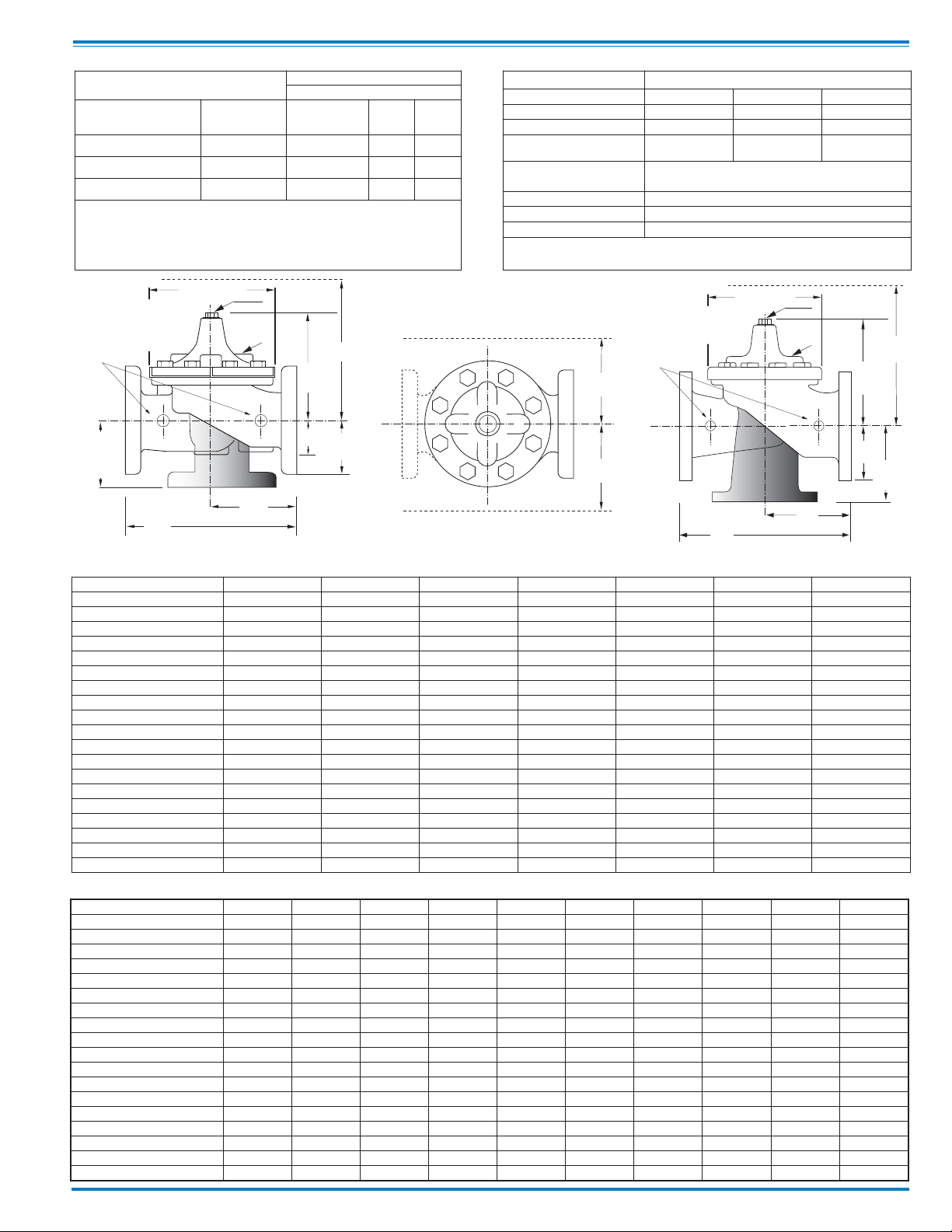
Pressure Ratings
EE
D
E
Inlet
DD
AA
X
100-23
Flanged
F
A
C
(MAX)
K
J
H
Inlet
Outlet
FF
B
(Diameter)
Y
Z
Valve Body & Cover
Grade Material
ASTM A536 Ductile Iron B16.42 250 400
ASTM A216-WCB Cast Steel B16.5 285 400
ASTM B62 Bronze B16.24 225 400
Note: * ANSI standards are for flange dimensions only.
Flanged valves are available faced but not drilled.
100-04
Flanged
H
Inlet
GG
GGG
(Recommended Maximum Pressure - psi)
Pressure Class
Flanged
ANSI
Standards*
(Diameter)
B
J
K
C
(MAX)
E
X
Outlet
F
FF
150
Class
300
Class
Materials
Component Standard Material Combinations
Body & Cover Ductile Iron Cast Steel Bronze
100-04 Available Sizes 4" - 16" 4" - 16" 4" - 16"
100-23 Available Sizes 4" - 24" 4" - 16" 4" - 16"
Disc Retainer &
Diaphragm Washer
Trim: Disc Guide,
Seat & Cover Bearing
Disc Buna-N
Diaphragm Nylon Reinforced Buna-N
Stem, Nut & Spring Stainless Steel
For material options not listed, consult factory.
Cla-Val manufactures valves in more than 50 different alloys.
Cast Iron Cast Steel Bronze
Bronze is Standard
Stainless Steel is Optional
®
Rubber
®
Rubber
Inlet
AA
DD
DDD
AAA
60-31 Series Dimensions
Valve Size (Inches) 4 6 8 10 12 14 16
AA 150 ANSI
AAA 300 ANSI
B Dia.
C Max.
DD 150 ANSI
DDD 300 ANSI
E
F 150 ANSI
FF 300 ANSI
GG 150 ANSI
GGG 300 ANSI
H NPT Body Tapping
J NPT Cover Center Plug
K NPT Cover Tapping
Stem Travel
Approx. Ship Wt. Lbs.
X Pilot System 17 29 31 33 36 40 40
Y Pilot System 12 20 22 24 26 29 30
Z Pilot System 12 20 22 24 26 29 30
660-31 Series Dimensions
Valve Size (Inches)
A 150 ANSI
AA 300 ANSI
B Dia.
C Max.
D 150 ANSI
DD 300 ANSI
E 150 ANSI
EE 300 ANSI
F 150 ANSI
FF 300 ANSI
H NPT Body Tapping
J NPT Cover Center Plug
K NPT Cover Tapping
Stem Travel
Approx. Ship Wt. Lbs.
X Pilot System 15 27 30 33 36 36 41 40 46 55
Y Pilot System 11 18 20 22 24 26 26 30 30 30
Z Pilot System 11 18 20 22 24 26 26 30 30 30
(Full Internal Port 100-04)
15.00 20.00 25.38 29.75 34.00 39.00 41.38
15.62 21.00 26.38 31.12 35.50 40.50 43.50
11.50 15.75 20.00 23.62 28.00 32.75 35.50
10.62 13.38 16.00 17.12 20.88 24.19 25.00
7.50 10.00 12.69 14.88 17.00 19.50 20.69
7.81 10.50 13.19 15.56 17.75 20.25 21.75
3.19 4.31 5.31 9.25 10.75 12.62 15.50
4.50 5.50 6.75 8.00 9.50 10.50 11.75
5.00 6.25 7.50 8.75 10.25 11.50 12.75
5.00 6.00 8.00 8.62 13.75 14.88 15.69
5.31 6.50 8.50 9.31 14.50 15.62 16.50
3
⁄4
3
⁄4
3
⁄4
1.1 1.7 2.3 2.8 3.4 4.0 4.5
140 285 500 780 1165 1500 2265
(Reduced Internal Port 100-23)
4 6 8 10 12 14 16 18 20 24
13.88 17.75 21.38 26.00 30.00 34.25 35.00 42.12 48.00 48.00
14.50 18.62 22.38 27.38 31.50 35.75 36.62 43.63 49.62 49.75
9.12 11.50 15.75 20.00 23.62 27.47 28.00 35.44 35.44 35.44
8.62 11.62 15.00 17.88 21.00 20.88 25.75 25.00 31.50 31.50
6.94 8.88 10.69 ———————
7.25 9.38 11.19 ———————
5.50 6.75 7.25 ———————
5.81 7.25 7.75 ———————
4.50 5.50 6.75 8.00 9.50 11.00 11.75 15.88 14.56 17.00
5.00 6.25 7.50 8.75 10.25 — 12.75 15.88 16.06 19.00
.50.75.751111111
.50 .75 .75 1 1 1.25 1.25 2 2 2
.50.75.751111111
0.8 1.1 1.7 2.3 2.8 3.4 3.4 4.5 4.5 4.5
85 195 330 625 900 1250 1380 1500 2551 2733
3
⁄4
3
⁄4
3
⁄4
(In Inches)
11111
11
11111
(In Inches)
1
1
⁄4 11⁄2
2
Page 4

60-31
Valve
Selection
100-04 Pattern: Globe (G), Angle (A), End Connections: Threaded (T), Flanged (F) Indicate Available Sizes
Inches 2 21⁄2 3 4 6 8 10 12 14
mm 50 65 80 100 150 200 250 300 350
Basic Valve
100-04
Suggested
Flow
(gpm)
Suggested
Flow
(Liters/Sec)
Pattern
End Detail T, F T, F T, F T, F T, F T, F F F F
Maximum
Maximum
Intermittent
Maximum
Maximum
Intermittent
G, A G, A G, A G, A G, A G, A G, A G, A G, A
210 300 460 800 1800 3100 4900 7000 8400
260 370 580 990 2250 3900 6150 8720 10540
13 19 29 50 113 195 309 442 530
16 23 37 62 142 246 387 549 664
100-04 Series is the full internal port Hycheck.
660-31
Valve
Selection
Basic Valve
100-23
Inches 3 4 6 8 10 12 14 16 18 20 24
mm 80 100 150 200 250 300 350 400 450 500 600
Pattern
GG, AG, AG, AGGGGGGG
End Detail FFFFFFFFFFF
100-23 Pattern: Globe (G), Angle (A), End Connections: Flanged (F) Indicate Available Sizes
Suggested
Flow
Maximum
260 580 1025 2300 4100 6400 9230 9230 16500 16500 16500
(gpm)
Suggested
Flow
Maximum
16 37 65 145 258 403 581 581 1040 1040 1040
(Liters/Sec)
100-23 Series is the reduced internal port size version of the 100-04 Series.
L1
Auto
Off
1CR
Wiring Diagram
Auto-Off-Hand = Selector Switch
1CR = Relay, DPST Normally
Open
2CR = Relay, DPST Normally
Open
3CR = Relay, TPST Normally
Open
SW1= Switch, Remote Start,
Note: SW2and PVS supplied by
Cla-Val Co. All other electrical items
supplied by customer. SW2is
included in the X105L switch
assembly which is mounted on the
pump control valve cover.
Automatic
SW2= Switch, SPDT, Valve Limit
Switch Connect to N.C.
Terminal
Shown In Pump Off Position
COM.
SW
2
PVS = Pilot Valve Solenoid
M = Pump Motor Starter
Hand
A
H
N.C.
N.O.
SW
3CR
1
2
2CR
3CR
1CR
2CR
3
3CR
1
L2
1CR
PVS
2CR
3CR
M
Pilot System Specifications
Temperature Range
Water: to 180°F Max
Materials
Standard Pilot System Materials
Pilot Control: Bronze ASTM B62
Trim: Stainless Steel Type 303
®
Rubber: Buna-N
Synthetic Rubber
Optional Pilot System Materials
Pilot Systems are available with optional
Stainless Steel or Monel materials
Solenoid Control
Body:
Brass ASTM B283
Note: For optimum operation of built-in check feature, installation with valve stem vertically position is recommended.
P.O. Box 1325 • Newport Beach, CA 92659-0325 • Phone: 949-722-4800 • Fax: 949-548-5441 • E-mail: claval@cla-val.com • Website cla-val.com
©
CLA-VAL
Copyright Cla-Val 2013 Printed in USA Specifications subject to change without notice.
Enclosure:
General Purpose, Watertight 1,2,3,3S,4,4X
Optional: Class I, Division 2, Hazardous Locations
and Watertight Type 3, 3S, 4, 4X
Voltages:
100-240 V 50-60 Hz AC or DC
24-99 V 50-60 Hz AC or DC
2-24 V DC
Manual Operator Standard
Max. operating pressure differential: 300 psi
Coil:
Insulation molded Class F
Watts AC 2
When Ordering,
Please Specify
1. Catalog No. 60-31 or
No. 660-31
2. Valve Size
3. Pattern - Globe or Angle
4. Pressure Class (Flanged)
5. Trim Material
6. Electrical Selection
7. Desired Options
8. When Vertically Installed
(Flow Direction)
E-60-31/660-31 (R-1/2013)
 Loading...