

Page 1

INSTALLATION / OPERATION / MAINTENANCE
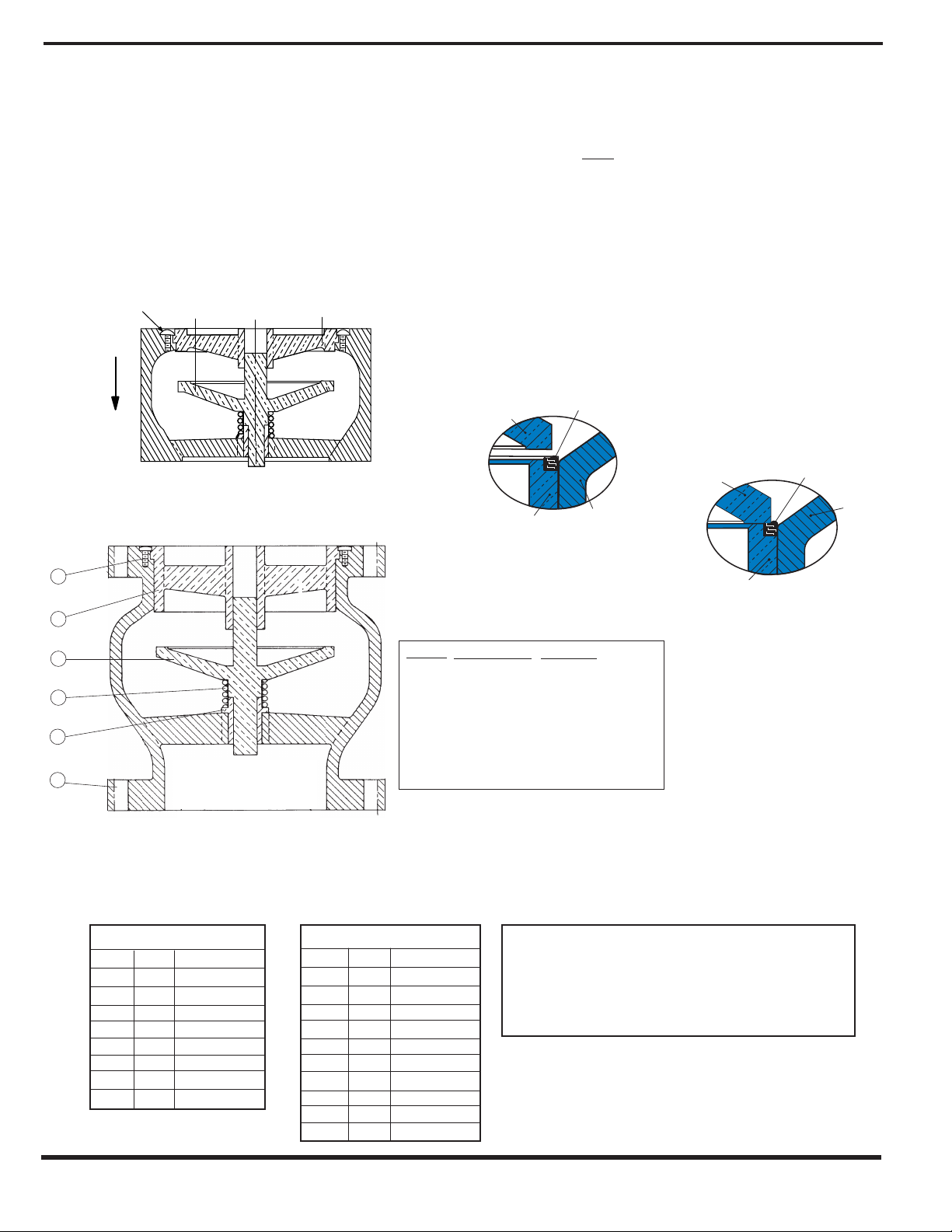
FLOW OPEN
See
Note 2
SERIES 580
WAFER STYLE CHECK VALVE
2" THRU 10"
1
2
6
3
4
5
Y
WAFER & GLOBE SILENT CHECK VALVES
OPERATION:
Cla-Val Silent Check Valves operate automatically, to open...
when pump flow starts and close silently ...when pump flow
stops.
INSTALLATION:
Silent Check Valves, Wafer and Globe style must be
installed between flat faced iron or steel flanges per ANSI
B16.5 or Awwa 207, utilizing a full faced gasket to bridge the
joint between the seat O.D. (2) and the body (1) flange face.
In this manner a pressure seal at this joint is made (see
Note 1). Install the valve so that the nameplate data is plainly read and the flow arrow points in the flow direction.
MAXIMUM ALLOWABLE INSIDE
DIAMETER OF FLANGE
(SEE NOTE No. 1)
VALV E
SIZE
21⁄2 2.940 14 14.140
3 3.570 16 16.160
4 4.570 18 18.180
5 5.660 20 20.200
6 6.720 24 24.250
8 8.720 30 30.250
10 10.880 36 36.250
12 12.880 42 42.250
Val ve
Size
21⁄2 2.875 4.875 5.125 14 14.000 17.750 19.125
3 3.50 5.375 5.875 16 16.000 20.250 21.250
4 4,50 6.875 7.125 18 18.00 21.625 23.500
5 5.562 7.750 8.500 20 20.00 23.875 25.750
6 6.625 8.75 9.875 24 24.000 28.250 30.500
8 8.625 11.000 12.125 30 30.000 34.750 37.500
10 10.750 13.375 14.250 36 36.000 41.250 44.000
12 12.750 16.125 16.625 42 42.000 48.000 50.750
MAINTENANCE:
Cla-Val Silent Check Valves are ruggedly designed for years of trouble-free
VALV E
A
SIZE
STANDARD RING GASKET DIMENSIONS (SEE NOTE No. 2)
I.D. For
125 Lb.
and
250 Lb.
Gasket
A
O.D. for
125 Lb.
Gasket
MAXIMUM ALLOWABLE INSIDE
(1/16" Maximum Thickness)
Note No. 1 - The mating companion flange I.D. must overlap the Valve seat.
O.D. for
250 Lb.
Gasket
A
DIAMETER OF FLANGE
(SEE NOTE NO. 1 )
ANSI B16.5 COMPANION
FLANGE WITH FLAT FACE
Ring or Full Faxe Gasket
This is required to achieve a seal between the seat O.D. and
The Body I.D. Interface area.
Val ve
Size
I.D. For
125 Lb.
250 Lb.
service. Therefore, regular maintenance is not required. However, during
initial start-up period the following problems may surfa ce (due to mis-application)
that can be easily resolved:
A. No Flow thru Valve:
1. Observe that the flow arrow name plate, on the
valve body, is pointing in the direction of flow.
2. Check that the down stream shut-off valve is full open.
B. Valve Chatters:
1. Confirm that the flow velocity is a minimum 3’/Sec.
2. Check that there is a minimum of 3 diameters of
straight pipe installed up stream of the silent check valve.
C. Valve Leakage:
1. Confirm a full face gasket is installed per Note 1.
and
Gasket
VALVE SEAT
VALVE DISC
Silent Check Valve - Flanged or Wafer Style
O.D. for
125 Lb.
Gasket
Series 581
Globe Style
Check Valve
2” thru 42”
Note 1: flanged gasket
must bridge this joint
for pressure seal
VALVE BOD
(Flanged Style Shown)
O.D. for
250 Lb.
Gasket
SERIES
580 & 581
Installed with name plate here
6
Detail
1
2
3
4
5
6
2
Description
Body
Seat*
Disc*
Spring*
Bushing*
Screw*
34
Note 2: All size 2” and 2 1/2” valves have
threaded seats in liev of screws
* Recommended Spare Part Kit
5
Material
Cast Iron
Bronze or SS
Bronze or SS
(Optional Buna-N
Stainless Steel
Bronze
Stainless Steel
(3” & larger valves)
1
®
)
Page 2
TO REMOVE VALVE FROM PIPELINE FOR INSPECTION:
DOWN STREAM
SIDE
UP STREAM
SIDE
REMOVE
CAP SCREWS
DISC
SEAT
FLOW
Plug
Seat
Body
Buna-N Seal
Open
®
Plug
Seat
Body
Buna-N Seal
Closed
®
CLA-VAL
Copyright Cla-Val 2011 Printed in USA Specifications subject to change without notice.
P.O. Box 1325 • Newport Beach, CA 92659-0325 • Phone: 949-722-4800 • Fax: 949-548-5441 • E-mail: claval@cla-val.com • Website cla-val.com
©
1. Shut off pump and pressure upstream and shut off isolation valve downstream
to completely isolate check valve. A skilled pipe fitter should be used for
this work.
2. Lay valve to rest on its downstream side and remove cap screws as
shown in Fig. 3. Note that 2" and 2-1/2" valves threaded seats in lieu of
cap screws.
3. Grip seat spokes by hand to pull out seats or push down the disc and
release quickly to allow force of the spring to pop out the seat.
4. With seat removed, check that all internal parts are freely removable from
valve body.
5. Examine all parts for wear/damage and order replacement PARTS KITS
as shown below.
Valve Open
Unseated
FIG. 3
6
UP STREAM
SIDE
Pressure
Silent Check Valve
Buna-N® Seating Detail
(Optional)
PROVIDES DROP-TIGHT SEATING
AT L OW
The unique seating action begins with the initial contact
between the metal valve disc and the Buna-N® Seal.
As pressure increases, Buna-N® seal is slightly compressed and allows the disc to make contact with the
metal portion of the valve seat. This metal-to-metal
contact prevents any further compression of the
Buna-N® seal. (Over compression of the synthetic
seal can lead to its destruction and cause potential
leakage.)
PRESSURES WITHOUT DAMAGE TO
BUNA-N
®
SEAL AT HIGHER PRESSURE
Valve Closed
Seated
with Pressure
2
3
4
5
1
Series 580 Wafer Style
Model Size Kits
580
580
580
580
580
580
580
580
2”
1/2”
2
3”
4”
5”
6”
8”
10”
DOWN STREAM
SIDE
A B C D
A B C D
A B C D
A B C D
A B C D
A B C D
A B C D
A B C D
Detail
Description
1
Body
2
Seat*
3
Plug*
4
Spring*
5
Bushing*
6
Screw*
Note 2: All size 2” and 2 1/2” valves have
threaded seats in liev of screws
* Recommended Spare Part Kit
Silent Check Valve Spare Part Kits
Series 581 Globe Style
Model Size Kits
2”
A
B
C
581
581
581
581
581
581
581
581
581
581
2
1/2”
3”
4”
5”
6”
8”
10”
12”
14”
A
A
A
A
A
A
A
A
A
D
B
C
D
B
C
D
B
C
D
B
C
D
B
C
D
B
C
D
B
C
D
B
C
D
B
C
D
Material
Cast Iron
Bronze or SS
Bronze or SS
(Optional Buna-N
Stainless Steel
Bronze
Stainless Steel
(3” & larger valves)
A- Kit Includes Detail 2 Bronze Seat & Detail 3 Disc
B- Kit Includes Detail 2 Stainless Steel Seat & Detail 3 Disc
C-Kit Includes Detail 2 Stainless Steel Seat, Detail 3
Disc, Detail 4 Spring, & Detail 5 Bronze Bushing
D-Kit Includes Detail 2 Stainless Steel Seat, Detail 3
Disc, Detail 4 Spring, & Detail 5 Stainless Steel Bushing
®
)
N-580/581 (R-3/2011)
 Loading...