

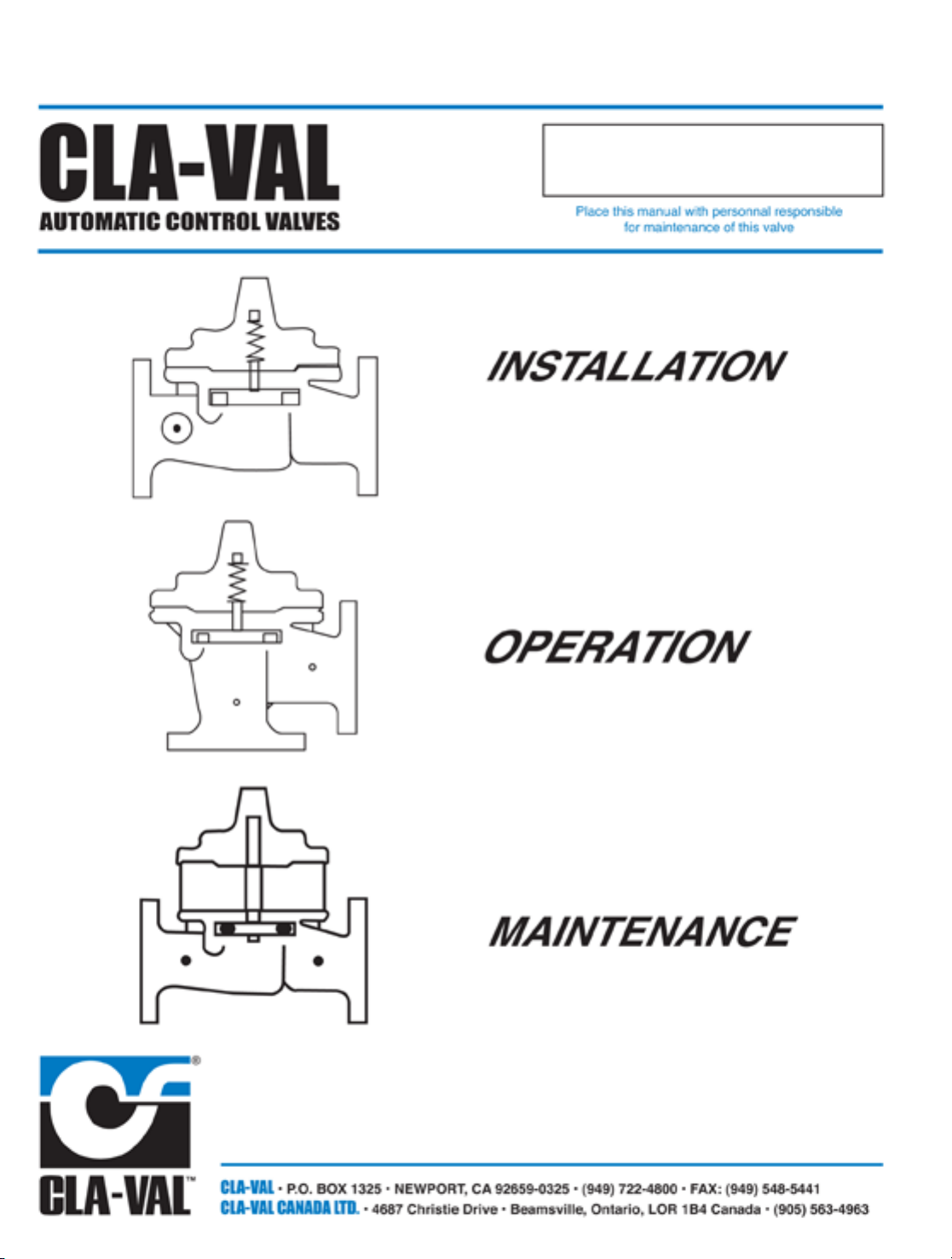
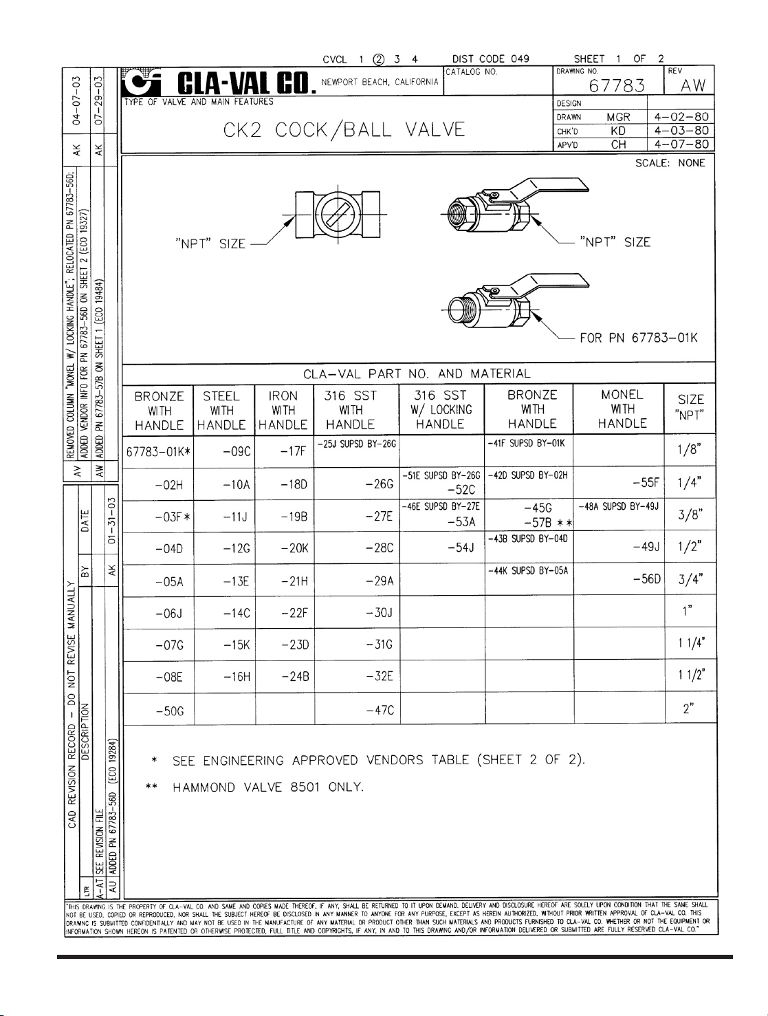
Page 1
50-49/650-49
Page 2

Page 3
Page 4

Page 5

• Drip - tight, positive seating
• Service without removal from line
• Screwed or flanged ends
• Globe or angle pattern
• Every valve factory-tested
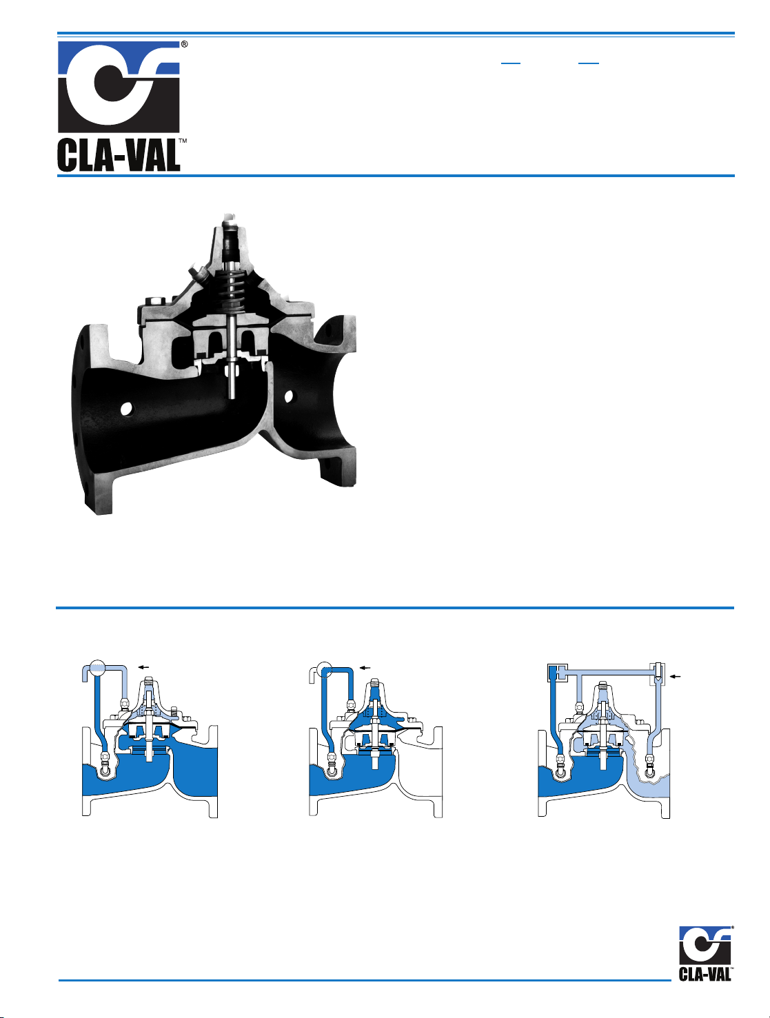
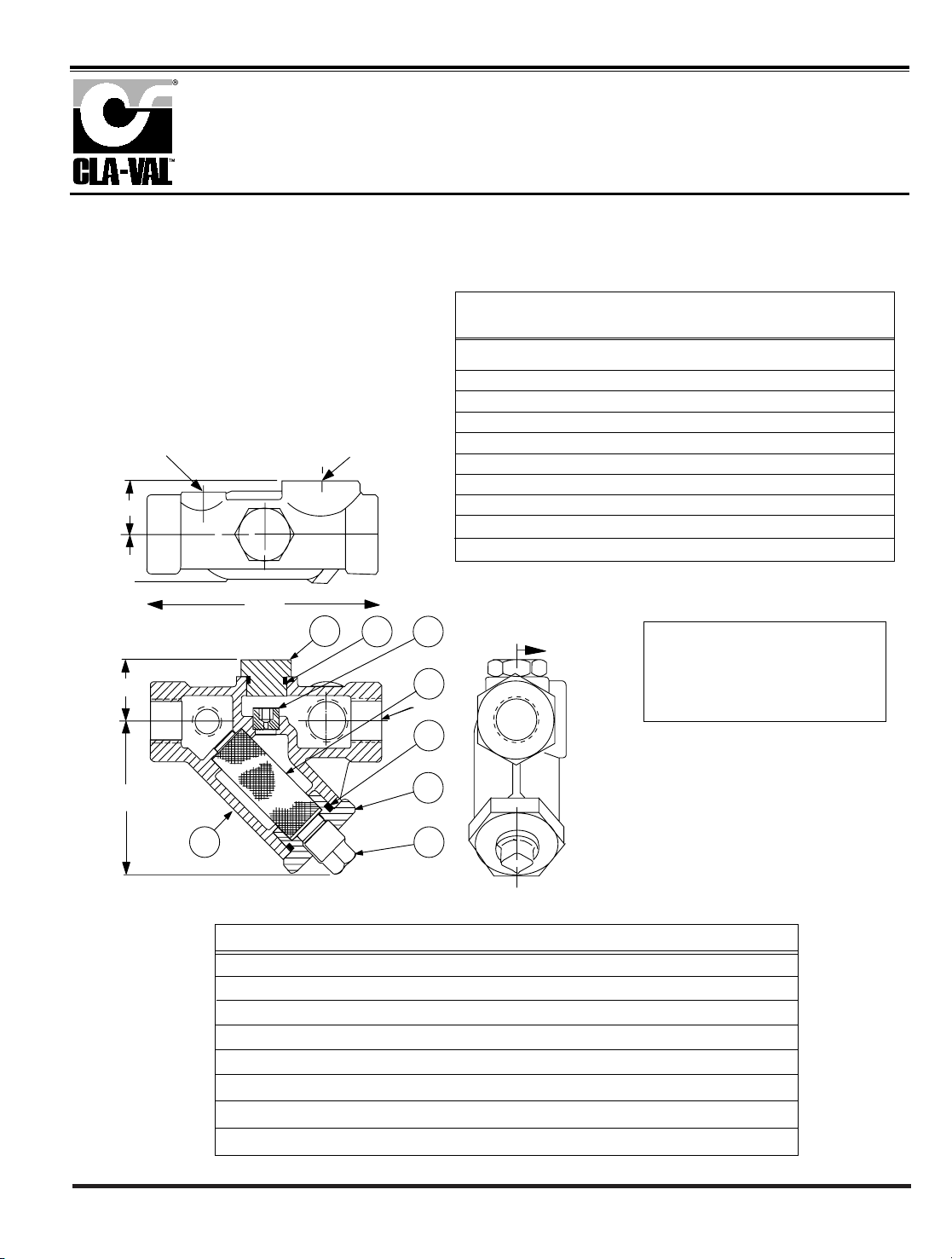
The Cla-Val Model 100S/2100S Seawater Service Hytrol Valve
is a hydraulically operated, diaphragm actuated, globe or
angle pattern valve. It consists of three major components:
body, diaphragm assembly and cover. The diaphragm assembly is the only moving part.
The body (ductile iron or cast steel) is epoxy coated and contains
a removable seat insert. The diaphragm assembly is guided top
and bottom by a precision machined stem. It utilizes a non-wicking diaphragm of nylon fabric bonded with synthetic rubber. A
resilient synthetic rubber disc retained on three and one half sides
by a disc retainer forms a drip-tight seal with the renewable seat
when pressure is applied above the diaphragm.
The Model 100S/2100S Seawater Service Hytrol Valve is the
basic valve used for seawater applications. It is the valve of
choice for system applications requiring deluge, pressure regulation, pressure relief, solenoid operation, rate of flow control, liquid level control or check valve operation. The rugged simplicity
of design and packless construction assure a long life of
dependable, trouble-free operation. It is available in various
materials and in a full range of sizes, with either screwed or
flanged ends. Its applications are unlimited.
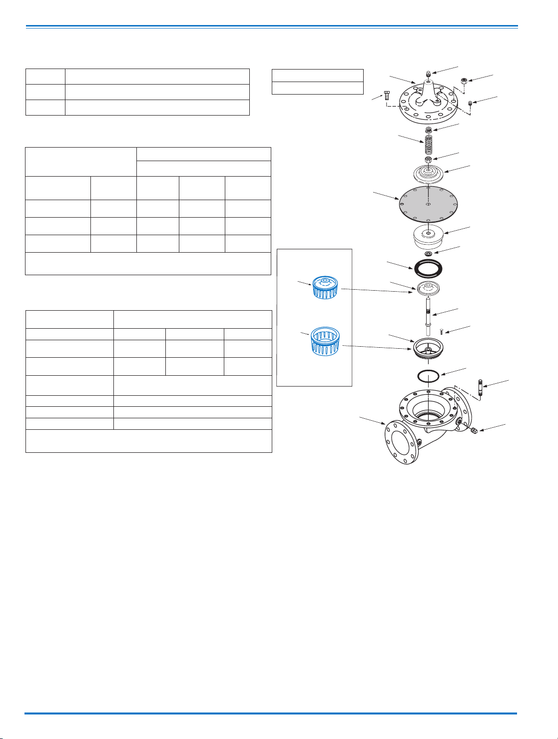
Modulating Action
The valve holds any intermediate position
when operating pressures are equal above
and below the diaphragm. A Cla-Val “modulating” pilot control will allow the
valve to automatically compensate for line pressure changes.
Principle of Operation
Full Open Operation
When pressure in the
cover chamber
is relieved to a zone of lower pressure, the line pressure at the valve
inlet opens the valve, allowing full flow.
Tight Closing Operation
When pressure from the valve inlet
is applied to the cover chamber, the
valve closes drip-tight.
Seawater Service Hytrol Valve
100S
2100S
MODEL
On-Off Control
Modulating
Control
On-Off Control
Page 6
Specifications
When Ordering, Please Specify:
1. Model No. 100S or No. 2100S
2. Valve Size
3. Pattern - Globe or Angle
4. Pressure Class
5. Screwed or Flanged
6. Temperature and fluid to be handled.
7. Static and Flowing Line Pressure.
8. Body & Trim Material
9. Desired Options
10. When Vertically Installed
Purchase Specifications
The Model 100S/2100S shall be a hydraulically operated, diaphragm-actuated, globe or
angle pattern valve. It shall contain a resilient, synthetic rubber disc, having a rectangular
cross-section, contained on three and one-half sides by a disc retainer and disc guide,
forming a tight seal against a single removable seat insert. The diaphragm assembly, containing a valve stem, shall be fully guided at both ends by a bearing in the valve cover and
an integral bearing in the valve seat. This diaphragm assembly shall be the only moving
part and shall form a sealed chamber in the upper portion of the valve, separating operating pressure from line pressure. The diaphragm shall consist of nylon fabric bonded with
synthetic rubber and shall not be used as a seating surface. Packing glands or stuffing
boxes are not permitted and there shall be no pistons operating the valve or its pilot controls. All necessary repairs shall be possible without removing the valve from the line. All
materials shall be compatible with seawater.
Valve shall be Model 100S/2100S manufactured by Cla-Val, Newport Beach, CA 92659-0325
For assistance in selecting appropriate valve options or valves manufactured with special design requirements, please contact our Regional Sales Office or Factory.
Available Sizes
Pattern Threaded Flanged Grooved End
Globe3⁄8" - 3" 11⁄2" - 36" 11⁄2"-2"- 3"- 4"- 6"
Angle 11⁄2" - 3" 2" - 16" 2" - 3" - 4"
Operating Temp. Range
Fluids
-40° to 180° F
Valve Body & Cover
Pressure Class
Flanged Threaded
Material
Material
Specifications
ANSI
Standards**
150 Lb. 300 Lb.
End***
Details
Ductile Iron* ASTM-A536 B16.42 250 400 400
Cast Steel* ASTM A216 B16.5 285 400 400
Naval Bronze ASTM B61 B16.24 225 400 400
Stainless Steel
Type 316
ASTM A743-CF-8M B16.5 285 400 400
NI.AL.Bronze ASTM B148 B.16.24 225 400 400
Super Duplex
Stainless Steel
B16.5 285 400 400
Note: *Fusion Bonded Epoxy Coated Internal and External.
**ANSI Standards are for flanged dimensions only.
Flanged Valves are available faced but not drilled
***End Details machined to ANSI B2.1 specifications
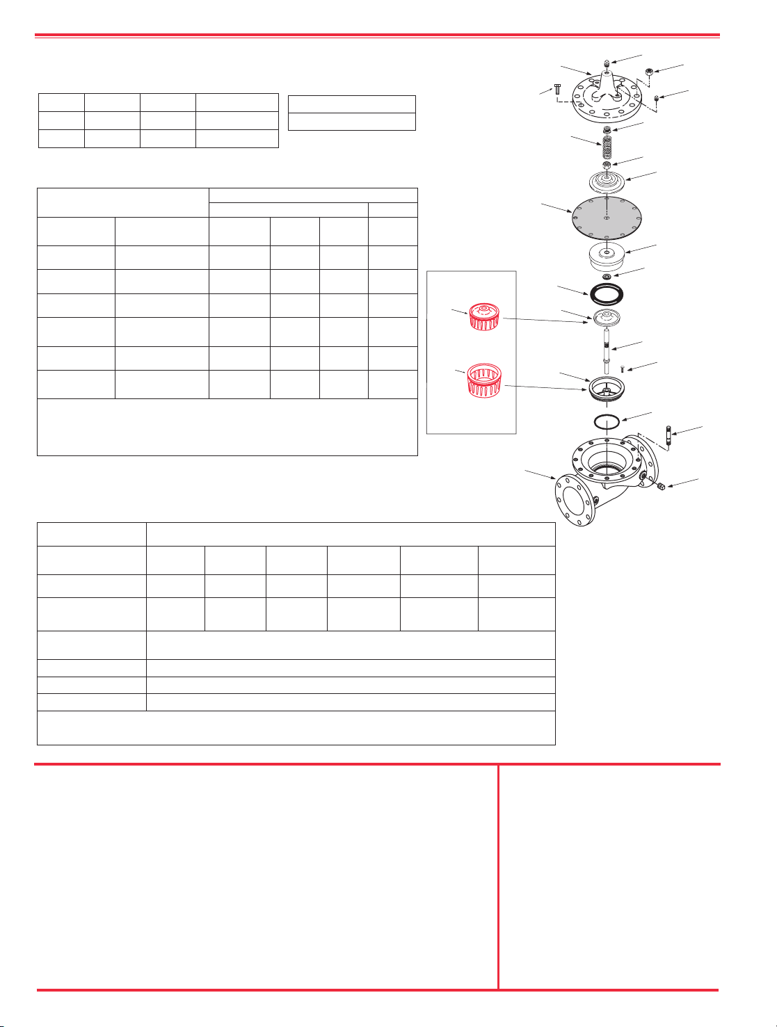
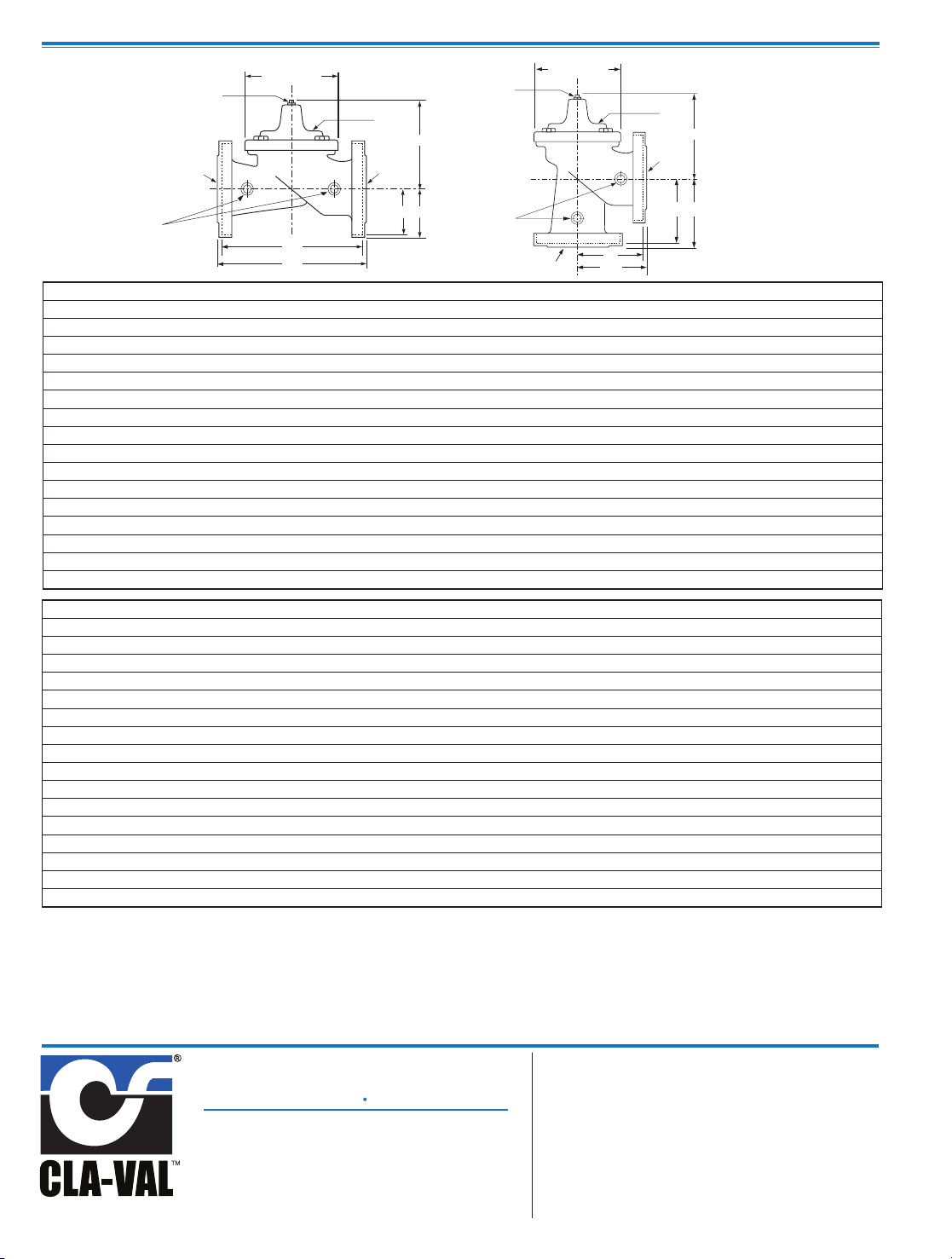
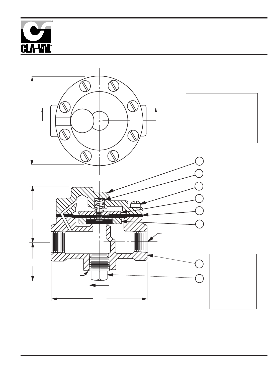
COVER
PIPE PLUG
COVER BEARING
SPRING
STEM NUT
DIAPHRAGM WASHER
DISC RETAINER
BODY
*
SPACER WASHERS
DISC GUIDE
SEAT
PIPE PLUG
STEM
SEAT O-RING
STUD
8" and Larger
*
DIAPHRAGM
*
DISC
*
Repair Parts
Seat Screw
8" and Larger
(Globe
or
Angle)
PIPE PLUG
HEX NUT
8" and Larger
Cover Bolt
6" and Smaller
KO
DISC GUIDE
KO
SEAT
KO Anti-Cavitation
Trim Option
(Patent Pending)
KO Anti-Cavitation Trim
can be added to any
standard Hytrol Valve
Component Standard Material Combinations
Body & Cover Ductile Iron Cast Steel Bronze
Stainless Steel
Type 316
NI. AL. Bronze
Super Duplex
Stainless Steel
Available Sizes 11⁄4" - 36" 11⁄4" - 16" 11⁄4" -16" 11⁄4" -16" 11⁄4" -16" 11⁄4" -16"
Disc Retainer &
Diaphragm Washer
Cast Iron Cast Steel Bronze Bronze Monel
Super Duplex
Stainless Steel
Trim: Disc Guide,
Seat & Cover Bearing
Bronze is Standard
Stainless Steel is optional
Disc Buna-N®Rubber
Diaphragm Nylon Reinforced Buna-N®Rubber
Stem, Nut & Spring Stainless Steel
For material options not listed, consult factory.
Cla-Val manufactures valves in more than 50 different alloys.
Materials
Pressure Ratings
(Recommended Maximum Pressure - psi)
Page 7
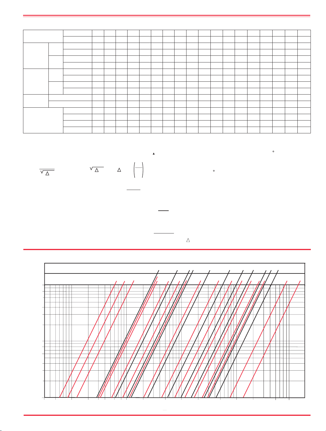
Model 100S/2100S Flow Chart (Based on normal flow through a wide open valve)
K =
894d
4
C
2
v
L =
K
12 f
K Factor (Resistance Coefficient)
The Value of K is calculated from the formula:
(U.S. system units)
Equivalent Length of Pipe
Equivalent lengths of pipe (L) are determined from the formula:
(U.S. system units)
Fluid Velocity
Fluid velocity can be calculated from the following formula:
(U.S. system units)
d
V =
.4085 Q
2
d
C
V
Factor
Formulas for computing C Factor, Flow (Q) and Pressure Drop
V
( P):
C
V
=
Q
P
C
V
=
Q
P
C
V
=
Q
P
2
V
Where:
U.S. (gpm) @ 1 psi differential at 60 F water
(l/s) @ 1 bar (14.5 PSIG) differential
or
at 15 C water
inside pipe diameter of Schedule 40 Steel Pipe (inches)
friction factor for clean, new Schedule 40 pipe
(dimensionless) (from Cameron Hydraulic Data,
18th Edition, P 3-119)
Resistance Coefficient (calculated)
Equivalent Length of Pipe (feet)
Flow Rate in U.S. (gpm) or (l/s)
Fluid Velocity (feet per second) or (meters per second)
Pressure Drop in (psi) or (bar)
=
=
=
=
=
=
=
=
=
P
V
Q
L
K
f
d
C
Functional Data Model 100S/2100S
*Estimated
Valve Size
Inches
3⁄81⁄23
⁄4 1 11⁄4 11⁄2 2 21⁄2 3 4 6 8 10 12 14 16 24 36
mm.
10 15 20 25 32 40 50 65 80 100 150 200 250 300 350 400 600 900
C
V
Factor
Globe
Pattern
Gal./Min. (gpm.)
1.8 6 8.5 13.3 30 32 54 85 11 5 200 440 770 1245 1725 2300 2940 7655 13320
Litres/Sec. (l/s.)
.43 1.44 2.04 3.2 7.2 7.7 13 20.4 27.6 48 105.6 184.8 299 414 552 706 1837 3200
Angle
Pattern
Gal./Min. (gpm.)
— — — — — 29 61 101 139 240 541 990 1575 2500* 3060* 4200* — —
Litres/Sec. (l/s.)
— — — — — 7 14.6 24.2 33.4 58 130 238 378 600 734.4 1008 — —
Equivalent
Length
of
Pipe
Globe
Pattern
Feet (ft.)
25 7 16 23 19 37 51 53 85 116 211 291 347 467 422 503 628 1866
Meters (m.)
7.6 2.2 4.8 7.1 5.7 11.4 15.5 16.0 25.9 35.3 64.2 88.6 105.8 142.4 128.6 153.6 191.6 569
Angle
Pattern
Feet (ft.)
— — — — — 46 40 37 58 80 139 176 217 222* 238* 247* — —
Meters (m.)
— — — — — 13.9 12.1 11.4 17.8 24.5 42.5 53.6 66.1 67.8 72.7 75.2 — —
K
Factor
Globe Pattern
16.3 3.7 5.7 6.1 3.6 5.9 5.6 4.6 6.0 5.9 6.2 6.1 5.8 6.1 5.0 5.2 4.0 7.1
Angle Pattern
— — — — — 7.1 4.4 3.3 4.1 4.1 4.1 3.7 3.6 2.9 2.8 2.6 — —
Liquid Displaced from
Cover Chamber When
Valve Opens
Fl. Oz
.12 .34 .34 .70 — — — — — — — — — — — — — —
U.S. Gal.
— — — — .02 .02 .03 .04 .08 .17 .53 1.26 2.51 4.0 6.5 9.6 29 42
ml
3.5 10.1 10.1 20.7 75.7 75.7 121 163 303 643 — — — — — — — —
Litres
— — — — — — — — — — 2.0 4.8 9.5 15.1 24.6 36.2 109.8 159
10 20 30 40 60 80 100 200 500 1000 2000 5000 10,000 20,000 50,000
1
2
3
4
6
8
10
20
30
40
60
80
100
5 3
Angle Valve Sizes (Inches)
Globe Valve Sizes (Inches)
1/2 1
2
3 4
6
8 10
12
12
24
3/4
11/2
21/2
11/2
2 3
4 6 8 10
14
16
16
1
1/4
21/2
Pressure Drop — psi
14
Flow Rate gpm (water)
1
36
100,000
Page 8

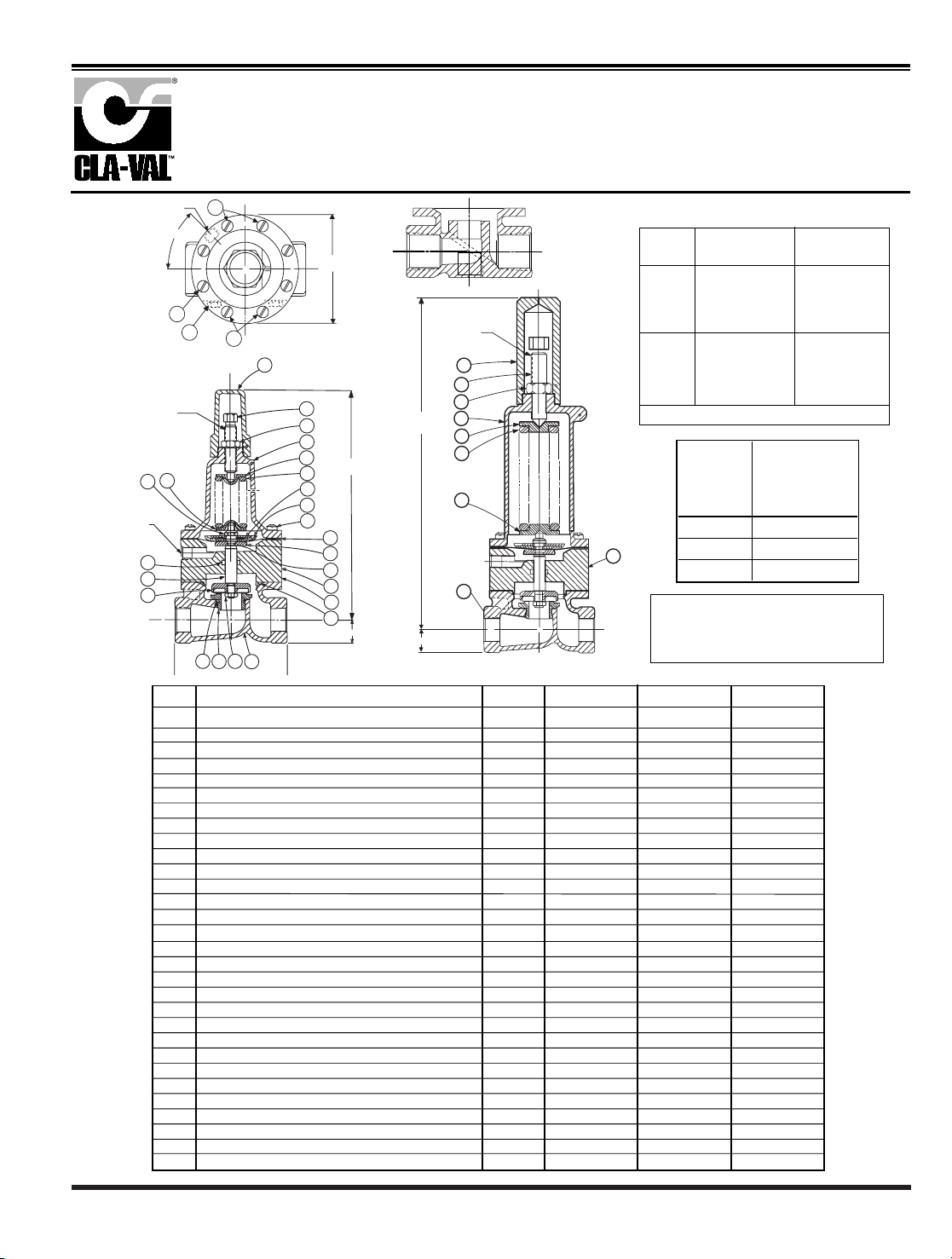
OUTLET
A
AA
AAA
E
INLET
H
J
B (DIAMETER)
K
FF
F
C
DDD
DD
INLET
OUTLET
C
H
B (DIAMETER)
K
GG
GGG
G
D
J
(MAX)
100S (Globe) 2100S (Angle) 100S Grooved (Globe) 2100S Grooved (Angle)
Dimensions
Model 100S
CLA-VAL
Copyright Cla-Val 2005 Printed in USA Specifications subject to change without notice.
P.O. Box 1325 • Newport Beach, CA 92659-0325 • Phone: 949-722-4800 • Fax: 949-548-5441 • E-mail: claval@cla-val.com • Website cla-val.com
©
E-100S/2100S (R-8/06)
Cla-Val Control Valves operate with maximum efficiency when mounted in horizontal piping with the main valve cover UP, however, other positions are acceptable. Due to
component size and weight of 8 inch and larger valves, installation with cover UP is advisable. We recommend isolation valves be installed on inlet and outlet for maintenance.
Adequate space above and around the valve for service personnel should be considered essential. A regular maintenance program should be established based on the specific
application data. However, we recommend a thorough inspection be done at least once a year. Consult factory for specific recommendations.
*11⁄2"Size Only
*40mm Size Only
Valve Size (Inches)
3⁄81
⁄2 - 3⁄4 1 11⁄4-11⁄2 2 21⁄2 3 4 6 8 10 12 14 16 24 36
A Threaded
2.75 3.50 5.12 7.25 9.38 11.00 12.50 — — — — — — — — —
AA 150 ANSI
— — — 8.50* 9.38 11.00 12.00 15.00 20.00 25.38 29.75 34.00 39.00 41.38 61.50 76.00
AAA 300 ANSI
— — — 9.00* 10.00 11.62 13.25 15.62 21.00 26.38 31.12 35.50 40.50 43.50 63.24 78.00
AAAA Grooved End
— — — 8.50 9.00 11.00 12.50 15.00 20.00 25.38 — — — — — —
B Dia.
2.50 3.12 4.38 5.62 6.62 8.00 9.12 11.50 15.75 20.00 23.62 28.00 32.75 35.50 53.16 66.00
C Max.
2.00 3.00 2.75 5.50 6.50 7.56 8.19 10.62 13.38 16.00 17.12 20.88 24.19 25.00 43.93 61.50
CC Max. Grooved End
— — — 4.75 5.75 6.88 7.25 9.62 12.12 14.62 — — — — — —
D Threaded
— — — 3.25 4.75 5.50 6.25 — — — — — — — — —
DD 150 ANSI
— — — 4.00* 4.75 5.50 6.00 7.50 10.00 12.75 14.88 17.00 19.50 20.81 — —
DDD 300 ANSI
— — — 4.25* 5.00 5.88 6.38 7.88 10.50 13.25 15.56 17.75 20.25 21.62 — —
DDDD Grooved End
— — — — 4.75 — 6.00 7.50 — — — — — — — —
E
1.25 0.88 1.63 1.12 1.50 1.69 2.56 3.19 4.31 5.31 9.25 10.75 12.62 15.50 17.75 24.56
EE Grooved End
— — — 2.00 2.50 2.88 3.12 4.25 6.00 7.56 — — — — — —
F 150 ANSI
— — — 2.50 3.00 3.50 3.75 4.50 5.50 6.75 8.00 9.50 10.50 11.75 19.25 28.00
FF 300 ANSI
— — — 3.06 3.25 3.75 4.13 5.00 6.25 7.50 8.75 10.25 11.50 12.75 — —
G Threaded
— — — 1.88 3.25 4.00 4.50 — — — — — — — — —
GG 150 ANSI
— — — 4.00* 3.25 4.00 4.00 5.00 6.00 8.00 8.62 13.75 14.88 15.69 — —
GGG 300 ANSI
— — — 4.25* 3.50 4.31 4.38 5.31 6.50 8.50 9.31 14.50 15.62 16.50 — —
GGGG Grooved End
— — — — 3.25 — 4.25 5.00 — —
— — — — — —
H NPT Body Tapping
—
1
⁄8
1
⁄4
3
⁄8
3
⁄8
1
⁄2
1
⁄2
3
⁄4
3
⁄4
1 1 1 1 1 1 2
J NPT Cover Center Plug
1
⁄
8
1
⁄
8
1
⁄
4
1
⁄
4
1
⁄
2
1
⁄
2
1
⁄
2
3
⁄
4
3
⁄
4
1 1
1
1
⁄
4
1
1
⁄
2
2
1
1
⁄
2
2
K NPT Cover Tapping
—
1
⁄8
1
⁄4
3
⁄8
3
⁄8
1
⁄2
1
⁄2
3
⁄4
3
⁄4
1 1 1 1 1 1 2
Valve Stem Internal
Thread UNF
— — — 10-32 10-32 10-321⁄4-281⁄4-283⁄8-243⁄8-243⁄8-243⁄8-243⁄8-241⁄2-203⁄4-163⁄4-16
Stem Travel
— — —
0.4 0.6 0.7 0.8 1.1 1.7 2.3 2.8 3.4 4.0 4.5 6.75 10.12
Approx. Ship Wt. Lbs.
3 3 8 15 35 50 70 140 285 500 780 1165 1600 2265 6200 11470
Valve Size (mm) 10 15-20 25 32-40 50 65 80 100 150 200 250 300 350 400 600 900
A Threaded
70 89 130 184 238 279 318 — — — — — — — — —
AA 150 ANSI
— — — 216* 238 279 305 381 508 645 756 864 991 1051 1562 1930
AAA 300 ANSI
— — — 229* 254 295 337 397 533 670 790 902 1029 1105 1606 1981
AAAA Grooved End
— — — 216 228 279 318 381 508 645 — — — — — —
B Dia.
64 80 111 143 168 203 232 292 400 508 600 711 832 902 1350 1676
C Max.
51 76 70 140 165 192 208 270 340 406 435 530 614 635 111 6 1562
CC Max. Grooved End
— — — 120 146 175 184 244 308 371 — — — — — —
D Threaded
— — — 83 121 140 159 — — — — — — — — —
DD 150 ANSI
— — — 102* 121 140 152 191 254 324 378 432 495 528 — —
DDD 300 ANSI
— — — 108* 127 149 162 200 267 337 395 451 514 549 — —
DDDD Grooved End
— — — — 121 — 152 191 — — — — — — — —
E
32 23 42 29 38 43 65 81 110 135 235 273 321 394 451 624
EE Grooved End
— — — 52 64 73 79 108 152 192 — — — — — —
F 150 ANSI
— — — 64 76 89 95 114 140 171 203 241 267 298 489 711
FF 300 ANSI
— — — 78 83 95 105 127 159 191 222 260 292 324 — —
G Threaded
— — — 48 83 102 11 4 — — — — — — — — —
GG 150 ANSI
— — — 102* 83 102 102 127 152 203 219 349 378 399 — —
GGG 300 ANSI
— — — 102* 89 11 0 111 135 165 216 236 368 397 419 — —
GGGG Grooved End
— — — — 83 — 108 127 — — — — — — — —
H NPT Body Tapping
—
1
⁄8
1
⁄4
3
⁄8
3
⁄8
1
⁄2
1
⁄2
3
⁄4
3
⁄4
1 1 1 1 1 1 2
J NPT Cover Center Plug
1
⁄8
1
⁄8
1
⁄4
1
⁄4
1
⁄2
1
⁄2
1
⁄2
3
⁄4
3
⁄4
1 1
1
1
⁄4 11⁄2
2
1
1
⁄2
2
K NPT Cover Tapping
—
1
⁄8
1
⁄4
3
⁄8
3
⁄8
1
⁄2
1
⁄2
3
⁄4
3
⁄4
1 1 1 1 1 1 2
Valve Stem Internal
Thread UNF
— — — 10-32 10-32 10-321⁄4-281⁄4-283⁄8-243⁄8-243⁄8-243⁄8-243⁄8-241⁄2-203⁄4-163⁄4-16
Stem Travel
— — —
10 15 18 20 28 43 58 71 86 102 114 171 257
Approx. Ship Wt. Kgs.
1.4 1.4 4 7 16 23 32 64 129 227 354 528 726 1027 2812 5200
Page 9
MODEL
• Reduced Cavitation Design
• Drip-Tight, Positive Seating Action
• Service Without Removal From Line
• Globe or Angle Pattern
• Every Valve Factory Tested
The Cla-Val Model 100-20 Hytrol Valve is a hydraulically operated,
diaphragm actuated, globe or angle pattern valve. It consists of
three major components: body, diaphragm assembly and cover.
The diaphragm assembly is the only moving part.
The diaphragm assembly is guided top and bottom by a precision
machined stem which utilizes a non-wicking diaphragm of nylon
fabric bonded with synthetic rubber. A resilient synthetic rubber
disc, retained on three and one-half sides by a disc retainer, forms
a drip-tight seal with the renewable seat when pressure is applied
above the diaphragm.
The reduced cavitation characteristics of the 100-20 Hytrol Valve is
the basis for the Cla-Val 600 Series. The rugged simplicity of
design and packless construction assure a long life of dependable,
trouble-free operation. It's smooth flow passages and fully guided
disc and diaphragm assembly assure optimum control when used
in piping systems requiring remote control, pressure regulation,
solenoid operation, rate of flow control or check valve operation.
Available in various materials and in a wide range of sizes. It's
applications are unlimited.
100-20
600 Series
Hytrol Valve
Principle of Operation
Full Open Operation
When pressure in the
cover chamber
is relieved to a zone of lower
pressure, the line pressure at the
valve inlet opens the valve, allowing
full flow.
Modulating Action
The valve holds any intermediate
position when operating pressure is
equal above and below the
diaphragm. Using a Cla-Val
“Modulating” Control will allow the
valve to automatically compensate
for line pressure changes.
Tight Closing Operation
When pressure from the valve inlet
is applied to the cover chamber, the
valve closes drip-tight.
On-Off Control
On-Off Control
Modulating
Control
(Reduced Internal Port)
Page 10
Options
Specifications
Model 100-20
Pressure Ratings
(Recommended Maximum Pressure - psi)
Valve Body & Cover
Pressure Class
Flanged
Grade Material
ANSI
Standards*
150 lb. 300 lb.
ASTM A536 Ductile Iron B16.42 250 400
ASTM A216-WCB Cast Steel B16.5 285 400
ASTM B62 Bronze B16.24 225 400
Note: *ANSI standards are for flange dimensions only.
Flanged valves are available faced but not drilled.
Component Standard Material Combinations
Body & Cover Ductile Iron Cast Steel Bronze
Available Sizes 3" - 48" 3" - 16" 3" - 16"
Disc Retainer &
Diaphragm Washer
Cast Iron Cast Steel Bronze
Trim: Disc Guide,
Seat & Cover Bearing
Bronze is Standard
Stainless Steel is optional
Disc Buna-N®Rubber
Diaphragm Nylon Reinforced Buna-N®Rubber
Stem, Nut & Spring Stainless Steel
For material options not listed consult factory.
Cla-Val manufactures valves in more than 50 different alloys.
Materials
Operating Temp. Range
Available Sizes
Pattern Flanged
Globe 3", 4", 6", 8", 10", 12", 14", 16", 18", 20", 24", 30"
Angle 4", 6", 8"
Fluids
-40° to 180° F
COVER
PIPE PLUG
COVER BEARING
SPRING
STEM NUT
DIAPHRAGM WASHER
DISC RETAINER
BODY
*
SPACER WASHERS
DISC GUIDE
SEAT
PIPE PLUG
STEM
SEAT O-RING
STUD
10" and Larger
*
DIAPHRAGM
*
DISC
*
Repair Parts
Seat Screw
10" annd Larger
(Globe
or
Angle)
PIPE PLUG
HEX NUT
10" and Larger
Cover Bolt
6" and Smaller
KO
DISC GUIDE
KO
SEAT
KO Anti-Cavitation
Trim Option
(Patent Pending)
KO Anti-Cavitation Trim
can be added to any
standard Hytrol Valve
Viton®Rubber Parts- suffix KB
Optional diaphragm, disc and o-ring
fabricated with Viton
®
synthetic rubber.
Viton
®
is well suited for use with mineral
acids, salt solutions, chlorinated
hydrocarbons, and petroleum oils; and is
primarily used in high temperature
applications up to 250° F.
Do not use with
epoxy coatings above
175° F.
Epoxy Coating - suffix KC
An FDA approved fusion bonded epoxy
coating for use with cast iron, ductile iron
or steel valves. This coating is resistant to
various water conditions, certain acids,
chemicals, solvents and alkalies.
Epoxy
coatings are applied in accordance with
AWWA coating specifications C116-03.
Do not use with temperatures above
175° F.
Dura-Kleen® Stem - suffix KD
This stem is designed for applications
where water supplies containing dissolved
minerals create deposits that build-up on a
standard stem and hamper valve
operation. A patented, self-cleaning
design on the stem allows all valve sizes
to operate freely in the harshest
conditions.
Delrin
®
Sleeved Stem- suffix KG
The Delrin
®
sleeved stem is designed for
applications where water supplies contain
dissolved minerals which can form
deposits that build up on the valve stem
and hamper valve operation. Scale buildup will not adhere to the Delrin
®
sleeve
stem. Delrin
®
sleeved stems are not
recommended for valves in continuous
operation where differential pressures are
in excess of 80 psi (2" and larger Hytrol valves).
Heavy Spring
-
suffix KH
The heavy spring option is used in
applications where there is low differential
pressure across the valve, and the
additional spring force is needed to help
the valve close. This option is best suited
for valves used in on-off (non-modulating)
service.
Anti-Cavitation Trim
-
suffix KO
Anti-Cavitation Trim components consist
of a stainless steel radial slotted disc guide
and seat. This system is used when high
differentials are present across the valve.
Water Treatment Clearance
-
suffix KW
This additional clearance is beneficial in
applications where water treatment
compounds can interfere with the closing
of the valve. The smaller outside diameter
disc guide provides more clearance
between the disc guide and the valve seat.
This option is best suited for valves used
in on-off (non-modulating) service.
Page 11

Model 100-20 Flow Chart (Based on normal flow through a wide open valve)
20
24
10 20 30 40 60 80 100 200 500 1000 2000 5000 10,000 20,000 50,000
1
2
3
4
6
8
10
20
30
40
60
80
100
53
Angle Valve Sizes (Inches)
Globe Valve Sizes (Inches)
3
46
8
10 12
68
16
Pressure Drop — psi
4
18
30
14
Flow Rate gpm (water)
K =
894d
4
C
2
v
L =
K
12 f
K Factor (Resistance Coefficient)
The Value of K is calculated from the formula:
(U.S. system units)
Equivalent Length of Pipe
Equivalent lengths of pipe (L) are determined from the formula:
(U.S. system units)
Fluid Velocity
Fluid velocity can be calculated from the following formula:
(U.S. system units)
d
V =
.4085 Q
2
d
C
V
Factor
Formulas for computing C Factor, Flow (Q) and Pressure Drop
V
( P):
C
V
=
Q
P
C
V
=
Q
P
C
V
=
Q
P
2
V
Where:
U.S. (gpm) @ 1 psi differential at 60 F water
(l/s) @ 1 bar (14.5 PSIG) differential
or
at 15 C water
inside pipe diameter of Schedule 40 Steel Pipe (inches)
friction factor for clean, new Schedule 40 pipe
(dimensionless) (from Cameron Hydraulic Data,
18th Edition, P 3-119)
Resistance Coefficient (calculated)
Equivalent Length of Pipe (feet)
Flow Rate in U.S. (gpm) or (l/s)
Fluid Velocity (feet per second) or (meters per second)
Pressure Drop in (psi) or (bar)
=
=
=
=
=
=
=
=
=
P
V
Q
L
K
f
d
C
Functional Data Model 100-20
*Estimated
Valve Size
Inches 3 4 6 8 10 12 14 16 18 20 24 30
mm. 80 100 150 200 250 300 350 400 460 500 600 760
C
V
Factor
Globe
Pattern
Gal./Min. (gpm.) 62 136 229 480 930 1458 1725 2110 2940* 3400* 4020 7900*
Litres/Sec. (l/s.) 15 32.5 55 115 223 350 414 506 705 816 965 1895
Angle
Pattern
Gal./Min. (gpm.) — 135 233 545 — — — — — — — —
Litres/Sec. (l/s.) — 32 56 132 — — — — — — — —
Equivalent
Length
of
Pipe
Globe
Pattern
Feet (ft.) 293 251 777 748 621 654 750 977 983 1125 3005 2130
Meters (m.) 89.3 76.4 237.1 228.1 189.5 199.4 228.7 298.1 299.9 343.2 916.6 649.6
Angle
Pattern
Feet (ft.) — 254 751 580 — — — — — — — —
Meters (m.) — 77.6 229 176.9 — — — — — — — —
K
Factor
Globe Pattern 20.6 12.7 23.1 15.7 10.4 8.5 8.9 10.2 8.4 8.8 19.1 10.5
Angle Pattern — 12.9 22.3 12.2 — — — — — — — —
Liquid Displaced
from Cover Chamber
When Valve Opens
Fl. Oz — — — — — — — — — — — —
U.S. Gal. 0.32 .08 .17 .53 1.26 2.51 4.0 4.0 9.6 9.6 9.6 29.0
ml — — — — — — — — — — — —
Litres .12 .30 .64 2.0 4.8 9.5 15.1 15.1 36.2 36.2 36.2 110
Page 12
PO Box 1325 Newport Beach CA 92659-0325
Phone: 949-722-4800 Fax: 949-548-5441
CLA-VAL
CLA-VAL CANADA CLA-VAL EUROPE
4687 Christie Drive
Beamsville, Ontario
Canada LOR 1B4
Phone: 905-563-4963
Fax: 905-563-4040
Chemin dés Mesanges 1
CH-1032 Romanel/
Lausanne, Switzerland
Phone: 41-21-643-15-55
Fax: 41-21-643-15-50
©COPYRIGHT CLA-VAL 2006 Printed in USA
Specifications subject to change without notice.
www.cla-val.com
E-100-20 (R-8/06)
Represented By:
B (DIAMETER)
J
INLET
H
A
AA
K
C
OUTLET
F
FF
J
B
(DIAMETER)
K
C
OUTLET
E
EE
INLET
D
DD
H
100-20 (Angle)
100-20 (Globe)
Dimensions
Model 100-20
Service and Installation
Cla-Val Control Valves operate with maximum efficiency when mounted in horizontal piping with the main valve cover UP, however, other
positions are acceptable. Due to component size and weight of 10 inch and larger valves, installation with cover UP is advisable. We recommend
isolation valves be installed on inlet and outlet for maintenance. Adequate space above and around the valve for service personnel should be
considered essential. A regular maintenance program should be established based on the specific application data. However, we recommend a
thorough inspection be done at least once a year. Consult factory for specific recommendations.
Valve Size (Inches) 3 4 6 8 10 12 14 16 18 20 24 30
A 150 ANSI 10.25 13.88 17.75 21.38 26.00 30.00 34.25 35.00 42.12 48.00 48.00 63.25
AA 300 ANSI 11.00 14.50 18.62 22.38 27.38 31.50 — 36.62 43.63 49.62 49.75 —
B Dia. 6.62 9.12 11.50 15.75 20.00 23.62 28.00 28.00 35.44 35.44 35.44 53.19
C Max. 7.00 8.62 11.62 15.00 17.88 21.00 20.88 25.75 25.00 31.00 31.00 43.94
D 150 ANSI — 6.94 8.88 10.69 — — — — — — — —
DD 300 ANSI — 7.25 9.38 11.19 — — — — — — — —
E 150 ANSI — 5.50 6.75 7.25 — — — — — — — —
EE 300 ANSI — 5.81 7.25 7.75 — — — — — — — —
F 150 ANSI 3.75 4.50 5.50 6.75 8.00 9.50 11.00 11.75 15.88 14.56 17.00 19.88
FF 300 ANSI 4.12 5.00 6.25 7.50 8.75 10.25 — 12.75 15.88 16.06 19.00 —
H NPT Body Tapping
3
⁄8
1
⁄2
3
⁄4
3
⁄4 1 1 1 1 1 1 1 1
J NPT Cover Center Plug
1
⁄2
1
⁄2
3
⁄4
3
⁄4 1 1 11⁄4 11⁄4 2 2 2 2
K NPT Cover Tapping
3
⁄8
1
⁄2
3
⁄4
3
⁄4 1 1 1 1 1 1 1 1
Valve Stem Internal Thread UNF 10-321⁄
4-28
1
⁄
4-28
3
⁄
8-24
3
⁄
8-24
3
⁄
8-24
3
⁄
8-24
3
⁄
8-24
1
⁄
2-20
1
⁄
2-20
1
⁄
2-20
3
⁄
4-16
Stem Travel 0.6 0.8 1.1 1.7 2.3 2.8 3.4 3.4 3.4 4.5 4.5 6.5
Approx. Ship Wt. Lbs. 45 85 195 330 625 900 1250 1380 1500 2551 2733 6500
Valve Size (mm) 80 100 150 200 250 300 350 400 450 500 600 750
A 150 ANSI 260 353 451 543 660 762 870 889 1070 1219 1219 1607
AA 300 ANSI 279 368 473 568 695 800 — 930 1108 1260 1263 —
B Dia. 168 232 292 400 508 600 711 711 900 900 900 1351
C Max. 178 219 295 381 454 533 530 654 635 787 787 1116
D 150 ANSI — 176 226 272 — — — — — — — —
DD 300 ANSI — 184 238 284 — — — — — — — —
E 150 ANSI — 140 171 184 — — — — — — — —
EE 300 ANSI — 148 184 197 — — — — — — — —
F 150 ANSI 95 114 140 171 203 241 279 298 403 370 432 505
FF 300 ANSI 105 127 159 191 222 260 — 324 403 408 483 —
H NPT Body Tapping
3
⁄8
1
⁄2
3
⁄4
3
⁄4 1 1 1 1 1 1 1 1
J NPT Cover Center Plug
1
⁄2
1
⁄2
3
⁄4
3
⁄4 1 1 11⁄4 11⁄4 2 2 2 2
K NPT Cover Tapping
3
⁄8
1
⁄2
3
⁄4
3
⁄4 1 1 1 1 1 1 1 1
Valve Stem Internal Thread UNF 10-321⁄4-281⁄4-283⁄8-243⁄8-243⁄8-243⁄8-243⁄8-241⁄2-201⁄2-201⁄2-203⁄4-16
Stem Travel 15 20 28 43 58 71 86 86 86 114 114 165
Approx. Ship Wt. Kgs. 20 39 89 150 284 409 568 627 681 1157 1249 2951
For assistance in selecting appropriate valve options or valves manufactured with special design requirements, please contact our Regional Sales Office or Factory.
Page 13

DESCRIPTION
The CRL Pressure Relief Control is a direct acting, spring loaded,
diaphragm type relief valve. It may be used as a self-contained valve or as
a pilot control for a Cla-Val Main valve. It opens and closes within very
close pressure limits.
INSTALLATION
The CRL Pressure Relief Control may be installed in any position. The
control body (7) has one inlet and one outlet port with a side pipe plug (24)
at each port. These plugs are used for control connections or gauge applications. The inlet in the power unit body (6) is the sensing line port. A flow
arrow is marked on the body casting.
OPERATION
The CRL Pressure Relief Control is normally held closed by the force of the
compression spring above the diaphragm; control pressure is applied
under the diaphragm.
When the controlling pressure exceeds the spring setting, the disc is lifted
off its seat, permitting flow through the control.
When controlling pressure drops below spring setting, the spring returns
the control to its normally closed position.
ADJUSTMENT PROCEDURE
The CRL Pressure Relief Control can be adjusted to provide a relief setting
at any point within the range found on the nameplate.
Pressure adjustment is made by turning the adjustment screw (9) to vary
the spring pressure on the diaphragm. Turning the adjustment screw clockwise increases the pressure required to open the valve. Counterclockwise
decreases the pressure required to open the valve.
When pressure adjustments are complete the jam nut (10) should be tightened and the protective cap (1) replaced. If there is a problem of tampering, lock wire holes have been provided in cap and cover. Wire the cap to
cover and secure with lead seal.
DISASSEMBLY
The CRL Pressure Relief Control does not need to be removed from the
line for disassembly. Make sure that pressure shut down is accompanied
prior to disassembly. If the CRL is removed from the line for disassembly
be sure to use a soft jawed vise to hold body during work.
Refer to Parts List Drawing for Item Numbers.
1. Remove cap (1), loosen jam nut (10) and turn adjusting
screw counterclockwise until spring tension is relieved.
2. Remove the eight screws (4) holding the cover (3) and
powerunit body (6). Hold the cover and powerunit together
and place on a suitable work surface.
See NOTE under REASSEMBLY.
3. Remove the cover (3) from powerunit body (6). The spring
(12) and two spring guides (11).
4. Remove nut (13) from stem (19) and slide off the belleville washer
(14), the upper diaphragm washer (15) and the diaphragm (16).
5. Pull the stem (19) with the disc retainer assembly (21) through the
bottom of powerunit. The lower diaphragm washer (17) will slide off
of stem top.
6. Remove jam nut (23) and disc retainer assembly (21) from stem.
Use soft jawed pliers or vise to hold stem. The polished surface of
stem must not be scored or scratched.
7. The seat (22) need not be removed unless it is damaged. If removal
is necessary use proper size socket wrench and turn counterclockwise.
Note: Some models have an integral seat in the body (7).
INSPECTION
Inspect all parts for damage, or evidence of cross threading. Check
diaphragm and disc retainer assembly for tears, abrasions or other damage. Check all metal parts for damage, corrosion or excessive wear.
REPAIR AND REPLACEMENT
Minor nicks and scratches may be polished out using 400 grit wet or dry
sandpaper fine emery or crocus cloth. Replace all O-rings and any damaged parts.
When ordering replacement parts, be sure to specify parts list item number and all nameplate data.
REASSEMBLY
In general, reassembly is the reverse of disassembly. However, the following steps should be observed:
1. Lubricate the O-Ring (18) with a small amount of a good grade of
waterproof grease, (Dow Corning 44 medium grade or equal).
Use grease sparingly and install O-ring in powerunit body (6).
2. Install stem (19) in powerunit body (6). Use a rotating motion with
minimum pressure to let stem pass through O-ring.
Do Not Cut O-Ring.
3. Install O-ring (5) at top of stem (19). Place lower diaphragm
washer (17) on the stem with the serrated side up. Position
diaphragm (16), upper diaphragm washer (15), with serration down,
and belleville washer (14) with concave side down.
4. Position powerunit body (6) as shown on parts list drawing (top view).
5. Continue reassembly as outlined in disassembly steps 1 through 3.
Pressure Relief Control
CRL
Note: Item (4) Screw will have a quantity of 8 for the 0-75 and 20-200psi
design and a quantity of 4 for the 100-300psi design. Item (25) Screw is
used on the 100-300psi design only. Install item (25), before item (4) for
preload of item (12) spring.
SYMPTOM PROBABLE CAUSE REMEDY
Fails to open. Controlling pressure
too low.
Back off adjusting
screw until valve
opens.
Fails to open with
spring compression
removed.
Mechanical obstruction, corrosion, scale
build-up on stem.
Disassemble,
locate,and remove
obstruction, scale.
Leakage from cover
vent hole when controlling pressure is
applied.
Diaphragm Damage Disassembly replace
damaged
diaphragm.
Fails to close with
spring compressed.
Mechanical obstruction.
Disassemble, locate
and remove
obstruction.
Fails to close. No spring compres-
sion.
Re-set pressure
adjustment.
Loose diaphragm
assembly.
Tighten upper
diaphragm washer.
MODEL
INSTALLATION / OPERATION / MAINTENANCE
CLA-VAL
Copyright Cla-Val 2005 Printed in USA Specifications subject to change without notice.
P.O. Box 1325 • Newport Beach, CA 92659-0325 • Phone: 949-722-4800 • Fax: 949-548-5441 • E-mail: claval@cla-val.com • Website cla-val.com
©
N-CRL (R-8/05)
Page 14
1/2" & 3/4" PRESSURE RELIEF CONTROL
CRL
Ajusting Screw
(3/8" - 16UNF THREAD)
9
1
10
3
11
12
14
13
11
8
22
23
7
18
19
21
INLET
1/8 - 27 NPT
SENSING
CONNECTION
(TYP.)
7.44
MAX
.71
OUTLET
20
6
2
0 TO 75 AND
20 TO 200 PSI DESIGN
5
17
16
15
4
1A
9
10
3
11
12
11
7
2
100 To 300 psi Design
.71
ADJUSTING SCREW
(1/2" 20UNF THREAD)
10.44
MAX.
When ordering parts please specify:
1. All Nameplate Data
2. Item Part Number
3. Item Description
CRL
RANGE PSI
APPROX. INCREASE
FOR EACH CLOCK-
WISE TURN OF
ADJUSTING SCREW
0 to 75 8.5 PSI
20 to 200 28.0 PSI
100 to 300 18.0 PSI
25
25
24
4
45º
3.12
DIA.
TRUE LOCATION OF
SENSING
CONNECTION
(TYP.)
ADJUSTING SO
(3/8" - 16UNF )
SIZE
1/2"
1/2"
1/2"
3/4"
3/4"
3/4"
SPRING
RANGE
0-75 PSI
20-200 PSI
100-300 PSI
0-75 PSI
20-200 PSI
100-300 PSI
PART
NUMBER
79222-01E
79222-02C
82809-01D
79229-01K
79229-02H
86005-01E
For 100-450 PSI Contact Factory
Body with
integral Seat
1
1A
2
3
4*
5*
6
7
8*
9
10
11
12
13
14
15
16*
17
18*
19
20*
21*
22
23
24
25*
Cap
Cap 100 to 300 psi Design
Nameplate
Cover
Screw Fil.Hd.10-32 x 1.88
0-Ring
Body, Powerunit
1/2" Body
3/4" Body
0-Ring, Seat
Screw, Adjusting
Nut Hex (Locking)
Guide, Spring
Spring,
Nut, Stem, Upper
Washer, Belleville
Washer, Diaphragm (upper)
Diaphragm
Washer, Diaphragm (lower)
0-Ring, Stem
Stem
0-Ring, Body
Retainer Assembly, Disc
Seat
Nut, hex, Stem, Lower
Pipe Plug
Screw Fil.Hd, 10-32 x 2.25 (Qty 4 on 100-300 psi)
FACTORY SET POINT
REPAIR KIT*
Plastic
Plastic
Brass
Bronze
303 SS
Rubber
Bronze
Bronze
Bronze
Rubber
Brass
303 SS
303 SS
CHR/VAN
Bronze
Steel
303 SS
Rubber
303 SS
Rubber
303 SS
Rubber
303 SS
303 SS
Bronze
Bronze
303 SS
0-75
67628J
1257601D
--
C2544K
6757867E
00902H
7920504D
C7928K
C9083B
00718H
7188201D
6780106J
71881H
71884B
73034B
7055007E
71891G
C1505B
45871B
00746J
8982401F
00767E
C8964D
62187A
6779806G
6784701C
6757867E
50 PSI
9170007A
20-200
67628J
1257601D
--
C2544K
6757867E
00902H
7920504D
C7928K
C9083B
00718H
7188201D
6780106J
71881H
71885J
73034B
7055007E
71891G
C1505B
45871B
00746J
8982401F
00767E
C8964D
62187A
6779806G
6784701C
6757867E
60 PSI
9170007A
100-300
1257601D
1257601D
--
44587E
6757867E
00902H
7920504D
C7928K
C9083B
00718H
7188201D
6780106J
1630301J
1630201A
73034B
7055007E
71891G
C1505B
45871B
00746J
8982401F
00767E
C8964D
62187A
6779806G
6784701C
6757867E
100 PSI
9170007A
Item Material Part Number
Part Number
Part Number
Description
CLA-VAL
Copyright Cla-Val 2005 Printed in USA Specifications subject to change without notice.
P.O. Box 1325 • Newport Beach, CA 92659-0325 • Phone: 949-722-4800 • Fax: 949-548-5441 • E-mail: claval@cla-val.com • Website cla-val.com
©
PL-CRL (R-12/05)
PARTS LIST
Page 15

*This drawing is the property of CLA-VAL and same and copies made thereof, if any, shall be returned to it upon demand. Delivery and disclosure hereof are made solely
upon condition that the same shall not be used, copied ore reproduced, nor shall the subject here of be disclosed in any manner to anyone for any purpose, except as
herein authorized, without prior approval of CLA-VAL. Whether or not the equipment or information shown hereon is patented or otherwise protected, full title and copyrights if any, in and to this drawing and/or information delivered or submitted are fully reserved by CLA-VAL.
Dwg#47117
Regulator Spring Color Coding Chart
THE FOLLOWING CONTROL & SPRING P/N#'S WERE REMOVED, 32656B, 31554K, 44591G, V65695B, & V5695B.
ADDED CRL-13, CRL-5A, CRA, CRA-10A, CHANGED SPRING RANGES TO MATCH CURRENT CONTROLS.
CLA-VAL
Copyright Cla-Val 2005 Printed in USA Specifications subject to change without notice.
P.O. Box 1325 • Newport Beach, CA 92659-0325 • Phone: 949-722-4800 • Fax: 949-548-5441 • E-mail: claval@cla-val.com • Website cla-val.com
©
PL-47117 AD (R-11/06)
PARTS LIST
WIRE SIZE SPRING NUMBER COLOR WIRE MATERIAL CATALOG NUMBER PSI RANGE *PSI PER TURN
.080 DIA. C0492D BLUE S.S.
CDB-7
CRL-5A
0-7
0-7
.75
.75
.018 DIA. 82575C -- S.S.
CRD
CRD-10A
1.9-6.5
1.9-6.5
.61
.49
.116 DIA. 81594E -- S.S.
CRD
CRD-10A
2-30
2-30
3.0
2.4
.120 DIA. V5654J GREEN CHR VAN
CRL-5A
CRD
5-25
10-40
4.0
4.0
.162 DIA. 32447F NATURAL S.S.
CDB-7
CRL-5A
CRL-13
10-60
10-60
10-60
12.0
12.0
12.0
.162 DIA. V5695B YELLOW MUSIC WIRE
CDB-7
CRL-5A
CRL-13
20-80
20-80
20-80
14.5
14.5
14.5
.207 DIA. C1124B CAD PLT MUSIC WIRE
CDB-7
CRL-13
CRL-5A
50-150
50-150
50-150
29.5
29.5
29.5
.225 DIA. V6515A RED MUSIC WIRE
CDB-7
CRL-13
CRL-5A
65-180
65-180
65-180
44.0
44.0
44.0
.115 X .218 71884B RED CHR VAN
CRL
CRD
CRD-10A
0-75
15-75
15-75
8.5
9.0
7.2
.118 X .225 71886J GREEN CHR VAN
CRL
CRD
CRD-10A
20-200
30-300
30-300
28.0
27.0
22.4
.225 X .295 1630201A CAD PLT CHR VAN
CRL
CRL-5A
100-300
100-300
18.00
18.00
.440 X .219 48211H CAD PLT STEEL
CRA-18
CRD-22
CRL-4A
200-450
200-450
100-450
17.0
17.0
17.0
.187 20561901H BLACK STEEL CRD 20-105 12.0
WIRE SIZE SPRING NUMBER COLOR WIRE MATERIAL CATALOG NUMBER PSI RANGE *FEET PER TURN
.080 DIA. C0492D BLUE S.S.
CRA
CRD-2
4.5-15
4.5-15
.82
.82
.375 DIA.
87719B
1 SPRING
2 SPRING
3 SPRING
4 SPRING
5 SPRING
EPOXY
COATED
CHROME SILICON CDS-5
5-40
30-80
70-120
110-120
150-200
1.0
2.0
3.0
4.0
5.0
.072 DIA. V5097A -- 302SS CVC 1-17 .7
.375 DIA.
2933502H
1 SPRING
2 SPRING
3 SPRING
4 SPRING
5 SPRING
EPOXY
COATED
CHROME SILICON CDS-6
5-40
30-80
70-120
110-120
150-200
.75
1.50
2.20
3.00
3.70
*THESE FIGURES ARE ONLY APPROXIMATE. FINAL ADJUSTMENTS SHOULD BE MADE WITH A PRESSURE GAGE.
Page 16
When ordering parts, please specify:
• All Nameplate Data
• Item Number
• Description
• Recommended Spare Parts
Strainer and Orifice Assembly
X44A
BRONZE BODY — S.S. ORIFICE
1/8 NPT
3/8 NPT
3/4
3/4
3 3/8
2
3
5
4
3/8 NPT
8
7
6
1
2 1/4 MAX.
7/8
Inlet
Outlet
X44A
STOCK NO.
71310-01
-02
-03
-04
-05
-06
* -07
-08
-09
-10
ORIFICE DIA.
.031
.046
.062
.078
.093
.109
.125
.140
.156
.187
ORIFICE PLUG
PART # (ITEM 5)
94132-01
-02
-03
-04
-05
-06
-07
-08
-09
-10
*Standard
3/8" x 3/8"
ITEM
1
2
3
4
5
6
7
8
DESCRIPTION
Body
Plug, Top
"O" Ring, Plug Top
Screen
Orifice Plug
Plug, Pipe
Strainer Plug
"O" Ring, Strainer Plug
MATERIAL
Red Brs.
Brass
Syn. Rub.
Monel
Delrin
Brass
S.S.
Syn. Rub.
QTY.
1
1
1
1
1
1
1
1
CLA-VAL
Copyright Cla-Val 2005 Printed in USA Specifications subject to change without notice.
P.O. Box 1325 • Newport Beach, CA 92659-0325 • Phone: 949-722-4800 • Fax: 949-548-5441 • E-mail: claval@cla-val.com • Website cla-val.com
©
P-X44A (R-5/05)
PARTS LIST
Page 17
A
2.50
A
2.75
SECTION
AA
3/8 N.P.T.
1.25
1.50
3/8 N.P.T.
BOTH ENDS
6
5
4
1
3
2
8
7
Outlet
Inlet
Flow
1. Cover Screw (8 Required)
2. Cover
*3. Spring
4. Diaphragm Washer
*5. Diaphragm
*6. Disc Retainer Assembly
7. Body Plug (3/8 NPT)
8. Body (Threaded)
ITEM DESCRIPTION
When ordering
parts, please
specify:
• All nameplate data
• Description
• Part Number
• Item Number
• Material
*Recommended Spare Parts
3/8" Check Valve
81-01
PARTS LIST
Page 18

2
10
7
6
9
11
3
5
1
4
8
3.50
.56
2.56
FLOW
OUTLETINLET
3.12 DIA
ITEM DESCRIPTION
When ordering
parts, please
specify:
• All nameplate data
• Description
• Part Number
• Item Number
• Material
*Recommended Spare Parts
1/2" & 3/4 Check Valve
81-01
CLA-VAL
Copyright Cla-Val 2005 Printed in USA Specifications subject to change without notice.
P.O. Box 1325 • Newport Beach, CA 92659-0325 • Phone: 949-722-4800 • Fax: 949-548-5441 • E-mail: claval@cla-val.com • Website cla-val.com
©
PL-81-01 (R-5/05)
PARTS LIST
1. Body 1
2. Cover 1
*3. Diaphragm 1
4. Guide Disc 1
*5. Disc Retainer Assembly 1
7. Nut Hex 3/8 - 24UNF 28 1
8. Plug Pipe Hex NPT 2
9. Screw, Fil HD 10 32UNF 2 x 2LG 8
10. Spring 1
11. Nameplate 1
Page 19

DESCRIPTION
The CRA Pressure Reducing Control automatically reduces a higher inlet
pressure to a lower outlet pressure. It is a direct acting, spring loaded,
diaphragm type valve that operates hydraulically or pneumatically and is
designed to sense pressure from a remote point. It may be used as a selfcontained valve or as a pilot control for a Cla-Val Co. main valve. It will
hold a constant downstream pressure at the remote sensing point within
very close pressure limits.
OPERATION
The CRA Pressure Reducing Control is normally held open by the force
of the compression spring above the diaphragm; delivery pressure acts on
the underside of the diaphragm. Flow through the valve responds to
changes in pressure at the the sensing point.
INSTALLATION
The CRA Pressure Reducing Control may be installed in any position.
There is one inlet port and two outlets, for either straight or angle installation. The second outlet port can be used for a gauge connection. A flow
arrow is marked on the body casting.
ADJUSTMENT PROCEDURE
The CRA Pressure Reducing Control can be adjusted to provide a delivery pressure range as specified on the nameplate.
Pressure adjustment is made by turning the adjustment screw to vary the
spring pressure on the diaphragm. The greater the compression on the
spring the higher the pressure setting.
1. Turn the adjustment screw in (clockwise) to increase delivery
pressure.
2. Turn the adjustment screw out (counter-clockwise) to decrease
the delivery pressure. When pressure adjustment is completed,
tighten jam nut on adjustment screw and replace protective cap.
Flow rates are not critical during pressure setting. The approximate minimum flow rates given in the table are for the main valve on which the CRA
is installed.
Valve Size 1 1⁄4"-3" 4"-8" 10"-16"
Minimum Flow GPM 15-30 50-200 300-650
MAINTENANCE
Disassembly
To disassemble follow the sequence of the item numbers assigned to
parts in the sectional illustration.
Reassembly
Reassembly is the reverse of disassembly. Caution must be taken to
avoid having the yoke (17) drag on the inlet nozzle of the body (18).
Follow this procedure:
1. Place yoke (17) in body and screw the disc retainer assembly
(16) until it bottoms.
2. Install gasket (14) and spring (19) for 2-30 psi range onto plug
(13) and screw into body. Disc retainer must enter guide hole in
plug as it is assembled. Screw the plug in by hand. Use wrench
to tighten only.
3. Place gasket (25) and powertrol body (21) on yoke extension
(17). Refer to sectional view for proper reassembly of (21) onto
body (18).
4. Place lower diaphragm washer (24), "o" ring (22), diaphragm
(12), upper diaphragm washer (11), and belleville washer (20) on
yoke extension (17). Screw on diaphragm nut (10) finger tight.
5. Place two machine screws (4) through (21) (25) and screw into
body (18). Do not include the diaphragm (12) in this operation.
This holds parts aligned for next step, and allows the diaphragm
to move and be properly located during tightening of nut (10).
6. Hold the diaphragm so that screw holes in the diaphragm (12)
SYMPTOM PROBABLE CAUSE REMEDY
Fails to open when
pressure lowers
No spring compression Tighten adjusting
screw
Mineral buildup on yoke
extension (17)
Disassemble and
clean part,
Replace "O" rings
(22) and (23).
Damaged spring Disassemble and
replace.
Spring guide (8) is not in
place
Disassemble and
place guide (8) on
top of spring (9).
Yoke dragging on inlet
nozzle
Disassembled
and reassemble
use procedure.
Fails to close when
delivery pressure rises
Spring compressed
Back off adjusting
screw
Mineral deposit on yoke
extension (17)
Disassemble and
clean part.
Replace "o" rings
(22) and (23).
Mechanical obstruction
Disassemble and
remove obstruction
Worn disc
Disassemble,
remove and
replace disc
retainer assembly. (16)
Yoke dragging on inlet
nozzle
Refer to paragraph 6
Damaged diaphragm (12)
Disassemble and
replace
Loose diaphragm nut (10)
Remove cover
and tighten nut
REMOTE SENSING TYPE
CRA
Leakage from cover
vent hole
MODEL
INSTALLATION / OPERATION / MAINTENANCE
CLA-VAL
Copyright Cla-Val 2005 Printed in USA Specifications subject to change without notice.
P.O. Box 1325 • Newport Beach, CA 92659-0325 • Phone: 949-722-4800 • Fax: 949-548-5441 • E-mail: claval@cla-val.com • Website cla-val.com
©
N-CRA (R-5/05)
and powertrol body (21) align. Tighten diaphragm nut (10) with a wrench.
At the final tightening release the diaphragm and permit it to rotate
approximately 5° to 10°. The diaphragm holes should now be properly
aligned with the body holes.
To check for proper alignment proceed as follows:
Rotate diaphragm clockwise and counterclockwise as far as possible.
Diaphragm screw holes should rotate equal distance on either side of
powertrol body screw holes ±1/8".
Repeat assembly procedure until diaphragm and yoke are properly
aligned. There must be no contact between yoke and body nozzle during
its normal opening and closing movement. To simulate this movement
hold powertrol body and diaphragm holes aligned. Move yoke to open
and closed positions. There must be no evidence of contact or dragging.
7. Remove machine screws per step 5.
8. Install spring (9) with spring guide (8) on top of spring.
9. Install cover (5) using eight machine screws (4).
10. Replace adjusting screw (2) and nut (3), then cap (1).
Pressure Reducing Control
Page 20
* Suggested Repair Parts
REMOTE SENSING TYPE
4
15
6
7
1/8" NPT
REMOTE
SENSING
CONNECTION
VIEW
C
FOR 20-300 PSI RANGE ONLY
16
SIZE
(inch)
STOCK
NUMBER
SEAT
DIA
ADJ.
RANGE
(psi)
3/8 79744-04B 1/4 30-300
3/8 79744-06G 1/4 2-30
Factory set pressure:
PSI*per turn
30-300 set @ 60 psi 27.0
2-30@ 10 psi 3.0
3/8 79744-03D 1/4 15-75
Pressure Reducing Control
CRA
When ordering parts specify:
• All nameplate data
• Description
• Item number
* Approximate - Final adjustment should
be made with a pressure gauge and
with flow.
15-75 set @ 20 psi 9.0
1
2
3
4*
5
6
7
8
9
10
11
12*
13
14*
15
16*
17
18
19*
20
21
22*
23*
24
25
Cap
Adjusting Screw
Jam Nut, 3/8—16
Machine Screw 10-32 x 1-1/4"(Fil.Hd.) (8 required)
Cover
Nameplate Screw
Nameplate
Spring Guide
Spring
(15-75 psi)
(30-300 psi)
(2-30 psi)
Hex Nut 5/16 - 18
Diaphragm Washer (upper)
Diaphragm
Plug, Body
Gasket
Plug, 3/8 NPT
Disc Retainer Assy (15-75 psi & 30-300 psi)
Disc Retainer Assy (2-30 psi)
Yoke
Body & Seat Assy, Seat only 1/4"
Bucking Spring (Required with 2-30 psi)
Belleville Washer
Powertrol Body
O-Ring
O-Ring
Diaphragm Washer (lower)
Gasket
Repair Kit (no Bucking Spring) Item 19
Repair Kit (with Bucking Spring) Item 19
PL
BRS
303
SS
BRS
SS
BRS
302
CHR VAN
CHR VAN
SS
303
302
NBR
BRS
FIB
BRS
BR/RUB
BR/RUB
VBZ
BS
302
STL
BRS
NBR
NBR
BRS
NBC
67628J
7188201D
6780106J
6757874A
C2544K
67999D
C002201G
71881H
71884B
71885B
81594E
71883D
71891G
C6936D
V5653A
40174F
6766003F
C5256H
C5255K
C1799A
8339701J
VO5586
7055007E
C3388A
00708J
00746J
C1804J
8059401D
9170003K
9170001D
ITEM DESCRIPTION MATERIAL PART NUMBER LIST PRICE
CLA-VAL
Copyright Cla-Val 2005 Printed in USA Specifications subject to change without notice.
P.O. Box 1325 • Newport Beach, CA 92659-0325 • Phone: 949-722-4800 • Fax: 949-548-5441 • E-mail: claval@cla-val.com • Website cla-val.com
©
PL-CRA (R-5/05)
PARTS LIST
Page 21
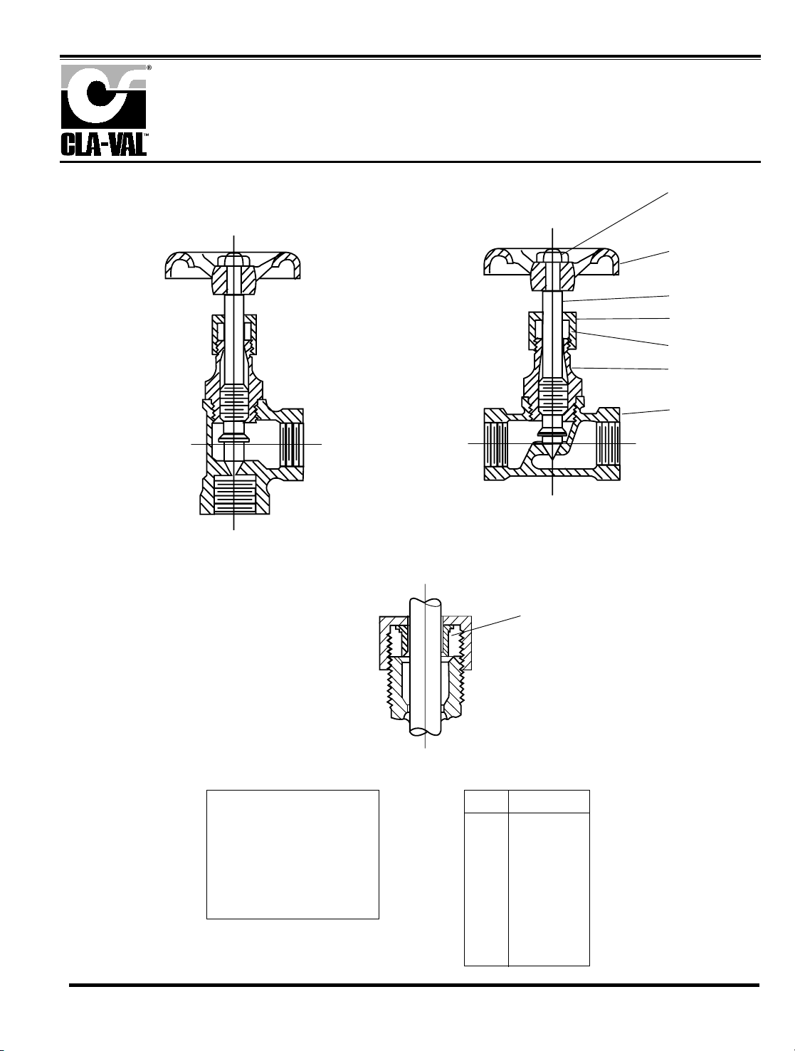
Globe and Angle Needle Valves—CN Series
1. Body
2. Bonnet
3. Stem
4. Gland
5. Nut
6. Handwheel
7. Nut
8. Packing
Item Description
When ordering parts,
please specify:
• All nameplate data
• Description
• Part Number
• Item Number
• Material
CN
7
6
3
5
8
2
1
3/4" SIZE ONLY
4
CAT. NO. CNB
GLOBE
CAT. NO. CNA
ANGLE
WHEN USED AS A CONTROL
VALVE, HANDWEEL IS
REMOVED AND STEM IS
SLOTTED FOR SCREWDRIVER ADJUSTMENT .
CLA-VAL
copyright Cla-Val 2003 Printed in USA Specifications subject to change without notice.
P.O. Box 1325 • Newport Beach, CA 92659-0325 • Phone: 949-722-4800 • Fax: 949-548-5441 • E-mail: claval@cla-val.com • Website cla-val.com
©
PL- CN (R-9/03)
PARTS LIST
Page 22
CLA-VAL
©Copyright Cla-Val 2005 Printed in USA Specifications subject to change without notice.
P.O. Box 1325 • Newport Beach, CA 92659-0325 • Phone: 949-722-4800 • Fax: 949-548-5441 • E-mail: claval@cla-val.com • Website cla-val.com
PL-CK2 (R-5/05)
Page 23
CLA-VAL
Copyright Cla-Val 2005 Printed in USA Specifications subject to change without notice.
P.O. Box 1325 • Newport Beach, CA 92659-0325 • Phone: 949-722-4800 • Fax: 949-548-5441 • E-mail: claval@cla-val.com • Website cla-val.com
©
INSTALLATION / OPERATION / MAINTENANCE
Flow Control
CV
MODEL
N-CV (R-5/05)
DESCRIPTION
The Cla-Val Model CV Flow Control is a simply-designed,
spring-loaded check valve. Rate of flow is full flow in one direction and restricted in other direction. Flow is adjustable in the
restricted direction. It is intended for use in conjunction with a
pilot control system on a Cla-Val Automatic Control Valve.
OPERATION
The CV Flow Control permits full flow from port A to B, and
restricted flow in the reverse direction. Flow from port A to B
lifts the disc from seat, permitting full flow. Flow in the reverse
direction seats the disc, causing fluid to pass through the clearance between the stem and the disc. This clearance can be
increased, thereby increasing the restricted flow, by screwing
the stem out, or counter-clockwise. Turning the stem in, or
clockwise reduces the clearance between the stem and the
disc, thereby reducing the restricted flow.’
INSTALLATION
Install the CV Flow Control as shown in the valve schematic
All connections must be tight to prevent leakage.
DISASSEMBLY
Follow the sequence of the item numbers assigned to the
parts in the cross sectional illustration for recommended
order of disassembly.
Use a scriber, or similar sharp-pointed tool to remove O-ring
from the stem.
INSPECTION
Inspect all threads for damage or evidence of crossthreading. Check mating surface of seat and valve disc for
excessive scoring or embedded foreign particles. Check
spring for visible distortion, cracks and breaks. Inspect all
parts for damage, corrosion and cleanliness.
CLEANING
After disassembly and inspection, cleaning of the parts can
begin. Water service usually will produce mineral or lime
deposits on metal parts in contact with water. These
deposits can be cleaned by dipping the parts in a 5-percent
muriatic acid solution just long enough for deposits to dissolve. This will remove most of the common types of
deposits. Caution: use extreme care when handling
acid. If the deposit is not removed by acid, then a fine grit
(400) wet or dry sandpaper can be used with water. Rinse
parts in water before handling. An appropriate solvent can
clean parts used in fueling service. Dry with compressed air
or a clean, lint-free cloth. Protect from damage and dust
until reassembled.
REPAIR AND REPLACEMENT
Minor nicks and scratches may be polished out using a fine
grade of emery or crocus cloth; replace parts if scratches
cannot be removed.
Replace O-ring packing and gasket each time CV Flow
Control is overhauled.
Replace all parts which are defective. Replace any parts
which create the slightest doubt that they will not afford completely satisfactory operation. Use Inspection steps as a
guide.
REASSEMBLY
Reassembly is the reverse of disassembly; no special tools
are required.
TEST PROCEDURE
No testing of the flow Control is required prior to reassembly
to the pilot control system on Cla-Val Main Valve.
Page 24
3/8" Flow Control
CV
2.12
MAX
STAMP PART NO. ON
SMOOTH SURFACE
RESTRICTED
FLOW
3/8 - 18 NPT
1.84
ADJUSTING STEM
(TURN CLOCKWISE TO
INCREASE RESTRICTION)
1
7
2
10
9
8
6
5
4
3
.85
FREE FLOW
BAR STOCK
CONFIGURATION
When ordering parts,
please specify:
• Number Stamped on Side
• Description (CV Flow Control)
• Part Description
• Material
ITEM DESCRIPTION QTY
1 Cap (SS only) 1
2 Nut, Jam 1
3 Seat 1
4 Gasket 1
5 Disc 1
6 Spring 1
7 Ring, Retaining 1
8 Stem 1
9 O-Ring 1
10 Housing 1
CLA-VAL
Copyright Cla-Val 2005 Printed in USA Specifications subject to change without notice.
P.O. Box 1325 • Newport Beach, CA 92659-0325 • Phone: 949-722-4800 • Fax: 949-548-5441 • E-mail: claval@cla-val.com • Website cla-val.com
©
PL-CV (R-5/05)
PARTS LIST
Page 25

3/8" Flow Control
CV
2.12
MAX
STAMP PART NO. ON
SMOOTH SURFACE
RESTRICTED
FLOW
3/8 - 18 NPT
1.84
ADJUSTING STEM
(TURN CLOCKWISE TO
INCREASE RESTRICTION)
1
7
2
10
9
8
6
5
4
3
.85
FREE FLOW
BAR STOCK
CONFIGURATION
When ordering parts,
please specify:
• Number Stamped on Side
• Description (CV Flow Control)
• Part Description
• Material
ITEM DESCRIPTION QTY
1 Cap (SS only) 1
2 Nut, Jam 1
3 Seat 1
4 Gasket 1
5 Disc 1
6 Spring 1
7 Ring, Retaining 1
8 Stem 1
9 O-Ring 1
10 Housing 1
CLA-VAL
Copyright Cla-Val 2005 Printed in USA Specifications subject to change without notice.
P.O. Box 1325 • Newport Beach, CA 92659-0325 • Phone: 949-722-4800 • Fax: 949-548-5441 • E-mail: claval@cla-val.com • Website cla-val.com
©
PL-CV (R-5/05)
PARTS LIST
Page 26

Cla-Val Product
Identification
Proper Identification
For ordering repair kits, replacement parts, or for
inquiries concerning valve operation, it is important to
properly identify Cla-Val products already in service
by including all nameplate data with your inquiry.
Pertinent product data includes valve function, size,
material, pressure rating, end details, type of pilot
controls used and control adjustment ranges.
Identification Plates
For product identification, cast-in body markings are
supplemented by identification plates as illustrated on
this page. The plates, depending on type and size of
product, are mounted in the most practical position. It
is extremely important that these identification
plates are not painted over, removed, or in any
other way rendered illegible.
INLET
EINTRITT
ENTREE
ENTRADA
SIZE &
CAT NO.
STOCK
NO.
CODE
MFD. BY CLA-VAL
NEWPORT BEACH, CALIF, U.S.A.
RESERVOIR
END
I
N
L
E
T
I
N
L
E
T
SIZE &
CAT NO.
STOCK
NO.
FLOW
MFD. BY CLA-VAL NEWPORT BEACH, CALIF. U.S.A.
CODE
C
¤
“
SIZE &
CAT NO.
STOCK
NO.
SPRING
RANGE
MFD. BY CLA-VAL NEWPORT BEACH, CALIF. U.S.A.
SIZE &
CAT NO.
STOCK
NO.
CODE
MFD. BY CLA-VAL
NEWPORT BEACH, CALIF.
U.S.A.
C
¤
“
DO NOT REMOVE
THIS VALVE HAS BEEN MODIFIED
SINCE ORIGINAL SHIPMENT FROM
FACTORY. WHEN ORDERING PARTS
AND/ OR SERVICE SUPPLY DATA FROM
THIS PLATE & ALL OTHER PLATES ON
ORIGINAL VALVE.
REDUCED PRESSURE BACKFLOW PREVENTION DEVICE
STK.
NO.
SER.
NO.
CAT.
NO.
RP
-4
CLA-VAL
NEWPORT BEACH, CA.
This brass plate appears on valves sized 21/2" and larger
and is located on the top of the inlet flange.
These two brass plates appear on 3/8", 1/2", and 3/4" size
valves and are located on the valve cover.
These two brass plates appear on threaded valves
1" through 3" size or flanged valves 1" through 2".
It is located on only one side of the valve body.
This brass plate appears on altitude valves only and is
found on top of the outlet flange.
This brass plate is used to identify pilot control valves.
The adjustment range is stamped into the plate.
This tag is affixed to the cover of the pilot control valve.
The adjustment range appears in the spring range section.
This aluminum plate is included in pilot system
modification kits and is to be wired to the new pilot
control system after installation.
This brass plate is used on our backflow prevention
assemblies. It is located on the side of the Number Two
check (2" through 10"). The serial number of the
assembly is also stamped on the top of the inlet flange of
the Number One check.
How to Order
Page 27

HOW TO ORDER
Because of the vast number of possible configurations and
combinations available, many valves and controls are not
shown in published product and price lists. For ordering
information, price and availability on product that are not listed,
please contact your local Cla-Val office or our factory office
located at:
SPECIFY WHEN ORDERING
• Model Number • Valve Size
• Globe or Angle Pattern • Threaded or Flanged
• Adjustment Range • Body and Trim Materials
(As Applicable) • Optional Features
• Pressure Class
UNLESS OTHERWISE SPECIFIED
• Globe or angle pattern are the same price
• Ductile iron body and bronze trim are standard
• X46 Flow Clean Strainer or X43 “Y” Strainer are included
• CK2 Isolation Valves are included in price on 4" and larger
valve sizes (6" and larger on 600 Series)
P. O. Box 1325
Newport Beach, California 92659-0325
(949) 722-4800
FAX (949) 548-5441
LIMITED WARRANTY
Automatic valves and controls as manufactured by Cla-Val are warranted
for three years from date of shipment against manufacturing defects in
material and workmanship that develop in the service for which they are
designed, provided the products are installed and used in accordance
with all applicable instructions and limitations issued by Cla-Val.
We will repair or replace defective material, free of charge, that is returned
to our factory, transportation charges prepaid, if upon inspection, the
material is found to have been defective at time of original shipment. This
warranty is expressly conditioned on the purchaser’s providing written
notification to Cla-Val immediate upon discovery of the defect.
Components used by Cla-Val but manufactured by others, are warranted
only to the extent of that manufacturer’s guarantee.
This warranty shall not apply if the product has been altered or repaired by
others, Cla-Val shall make no allowance or credit for such repairs or
alterations unless authorized in writing by Cla-Val.
DISCLAIMER OF WARRANTIES AND
LIMITATIONS OF LIABILITY
The foregoing warranty is exclusive and in lieu of all other
warranties and representations, whether expressed, implied, oral or
written, including but not limited to any implied warranties or
merchantability or fitness for a particular purpose. All such other
warranties and representations are hereby cancelled.
Cla-Val shall not be liable for any incidental or consequential loss,
damage or expense arising directly or indirectly from the use of the
product. Cla-Val shall not be liable for any damages or charges for
labor or expense in making repairs or adjustments to the product.
Cla-Val shall not be liable for any damages or charges sustained in
the adaptation or use of its engineering data and services. No
representative of Cla-Val may change any of the foregoing or
assume any additional liability or responsibility in connection with
the product. The liability of Cla-Val is limited to material
replacements F.O.B. Newport Beach, California.
TERMS OF SALE
ACCEPTANCE OF ORDERS
All orders are subject to acceptance by our main office at Newport Beach, California.
CREDIT TERMS
Credit terms are net thirty (30) days from date of invoice.
PURCHASE ORDER FORMS
Orders submitted on customer’s own purchase order forms will be accepted only
with the express understanding that no statements, clauses, or conditions contained
in said order form will be binding on the Seller if they in any way modify the Seller’s
own terms and conditions of sales.
PRODUCT CHANGES
The right is reserved to make changes in pattern, design or materials when deemed
necessary, without prior notice.
PRICES
All prices are F.O.B. Newport Beach, California unless expressly stated otherwise on
our acknowledgement of the order. Prices are subject to change without notice. The
prices at which any order is accepted are subject to adjustment to the Seller’s price
in effect at the time of shipment. Prices do not include sales, excise, municipal, state
or any other Government taxes. Minimum order charge $75.00.
RESPONSIBILITY
We will not be responsible for delays resulting from strikes, accidents, negligence of
carriers, or other causes beyond our control. Also, we will not be liable for any
unauthorized product alterations or charges accruing there from.
RISK
All goods are shipped at the risk of the purchaser after they have been delivered by
us to the carrier. Claims for error, shortages, etc., must be made upon receipt of
goods.
EXPORT SHIPMENTS
Export shipments are subject to an additional charge for export packing.
RETURNED GOODS
1. Customers must obtain written approval from Cla-Val prior to returning any
material.
2. Cla-Val reserves the right to refuse the return of any products.
3. Products more than six (6) months old cannot be returned for credit.
4. Specially produced, non-standard models cannot be returned for credit.
5. Rubber goods such as diaphragms, discs, o-rings, etc., cannot be returned for
credit, unless as part of an unopened vacuum sealed repair kit which is less
than six months old.
6. Goods authorized for return are subject to a 35% ($75 minimum) restocking
charge and a service charge for inspection, reconditioning, replacement of
rubber parts, retesting, repainting and repackaging as required.
7. Authorized returned goods must be packaged and shipped prepaid to Cla-Val,
1701 Placentia Avenue, Costa Mesa, California 92627.
PO Box 1325 Newport Beach CA 92659-0325
Phone: 949-722-4800 Fax: 949-548-5441
CLA-VAL
CLA-VAL CANADA CLA-VAL EUROPE
4687 Christie Drive
Beamsville, Ontario
Canada LOR 1B4
Phone: 905-563-4963
Fax: 905-563-4040
Chemin dés Mesanges 1
CH-1032 Romanel/
Lausanne, Switzerland
Phone: 41-21-643-15-55
Fax: 41-21-643-15-50
©COPYRIGHT CLA-VAL 2005 Printed in USA
Specifications subject to change without notice.
www.cla-val.com
E-Product I.D. (R-5/05)
Represented By:
Page 28
Complete Replacement Diaphragm Assemblies for 100-01 and 100-20 Hytrol Main Valves
For:
Hytrol Main Valves with Ductile Iron, Bronze Trim Materials—125/150 Pressure Class Only.
FACTORY ASSEMBLED
Includes: Stem, Disc Guide, Disc, Disc Retainer, Spacer Washers, Diaphragm, Diaphragm Washer
and Stem Nut.
3/8"
1/2" - 3/4"
1"
1 1/4"-1 1/2"
2"
2 1/2"
3"
4"
(Also 81-01 )
(Also 81-01 )
N/A
N/A
N/A
N/A
N/A
N/A
C2524B
C2525J
6"
8"
10"
12"
14"
16"
20"
24"
40456G
45276D
81752J
85533J
89067D
89068B
N/A
N/A
33273E
40456G
45276D
81752J
N/A
85533J
89068B
89068B
Valve
Size
Valve
Size
49097K
C2518D
C2520K
C2522 F
C2524B
C2523D
C2525J
33273E
100-01 100-20
Diaphragm Assembly
Stock Number
100-01 100-20
Diaphragm Assembly
Stock Number
3/8"
1/2" - 3/4"
1"
1 1/4" - 1 1/2"
2"
2 1/2"
3"
4"
6"
8"
10"
12"
14"
16"
20"
24"
(Also 81-01 )
(Also 81-01 )
N/A
N/A
N/A
N/A
N/A
N/A
9169805A
9169812G
9169813E
9169815K
9817901D
9817902B
N/A
9817903K
9817905E
9817905E
3/8"
1/2" - 3/4"
1"
1 1/4” - 1 1/2"
2"
2 1/2"
3"
4"
6"
8"
9169806J
9169807G
9169808E
9169809C
9169810A
9169817F
9169818D
9169819B
9169820K
9169834A
N/A
N/A
N/A
N/A
N/A
N/A
9169810A
9169818D
9169819B
9169820K
Valve
Size
Valve
Size
9169801K
9169802H
9169803F
9169804D
9169805A
9169811J
9169812G
9169813E
9169815K
9817901D
9817902B
9817903K
9817904H
9817905E
N/A
9817906C
100-01 100-20
Repair Kit
Stock Number
100-01 100-20
Repair Kit
Stock Number
Repair Kits for 100-01/100-20 Hytrol Valves
For:
Hytrol Main Valves—125/150 Pressure Class Only.
Includes: Diaphragm, Disc (or Disc Assembly) and spare Spacer Washers.
(Also 81-01 )
(Also 81-01 )
REPAIR KITS
When ordering, please give complete nameplate data of the valve and/or control being repaired.
MINIMUM ORDER CHARGE APPLIES.
Buna-N®Standard Material
Viton (For KB Valves)
MODEL
INSTALLATION / OPERATION / MAINTENANCE
Page 29

Repair Kits for 100-02/100-21 Powertrol and 100-03/100-22 Powercheck Main Valves
For:
Powertrol and Powercheck Main Valves—125/150 Pressure Class Only
Includes: Diaphragm, Disc (or Disc Assembly) and O-rings and full set of spare Spacer Washers.
Repair Kits for Pilot Control Valves
Includes: Diaphragm, Disc (or Disc Assembly), O-Rings, Gaskets or spare Screws as appropriate.
Repair Assemblies (In Standard Materials Only)
Repair Kits for 100-04/100-23 Hy-Check Main Valves
For:
Hy-Check Main Valves—125/150 Pressure Class Only
Includes: Diaphragm, Disc and O-Rings and full set of spare Spacer Washers.
CLA-VAL
Copyright Cla-Val 2007 Printed in USA Specifications subject to change without notice.
P.O. Box 1325 • Newport Beach, CA 92659-0325 • Phone: 949-722-4800 • Fax: 949-548-5441 • E-mail: claval@cla-val.com • Website cla-val.com
©
N-RK (R-5/07)
Larger Sizes: Consult Factory.
Valve
Size
Kit Stock Number
100-02
Valve
Size
Kit Stock Number
100-02 & 100-03 100-21 & 100-22
3
⁄
8”
9169901H
2
1
⁄2”
9169910J N/A
1
⁄2” &3⁄4”
9169902F
3”
9169911G 9169905J
1” 9169903D
4”
9169912E 9169911G
1
1
⁄4” &11⁄2”
9169904B
6”
9169913C 9169912E
2” 9169905J
8”
99116G 9169913C
10”
9169939H 99116G
12"
9169937B 9169939H
Larger Sizes: Consult Factory.
Valve
Size
Kit Stock Number
Valve
Size
Kit Stock Number
100-04 100-23 100-04 100-23
4” 20210901B N/A 12” 20210905H 20210904J
6” 20210902A 20210901B 14” 20210906G N/A
8” 20210903K 20210902A 16” 20210907F 20210905H
10” 20210904J 20210903K 20” N/A 20210907F
24” N/A 20210907F
BUNA-N®(Standard Material)
VITON (For KB Control)
Pilot
Control
Kit
Stock
Number
Pilot
Control
Kit
Stock
Number
Pilot
Control
Kit
Stock
Number
CDB 9170006C CRM-7 1263901K CDB-KB 9170012A
CDB-3D 9170023H CFM-7A 1263901K CRA-KB N/A
CDB-3I 9170024F CFM-9 12223E
CRD-KB
(w/bucking spring)
9170008J
CDB-7 9170017K
CRA
(w/bucking spring)
9170001D CRL-KB 9170013J
CDH-2 18225D
CRD (w/bucking spring)
9170002B CDHS-2BKB 9170010E
CDHS-2 44607A
CRD (no bucking spring)
9170003K CDHS-2FKB 9170011C
CDHS-2B 9170004H CRD-18 20275401K CDHS-18KB (no bucking spring) 9170009G
CDHS-2F 9170005E CRD-22 98923G
102C-KB
1726202D
CDHS-3C-A2 24657K CRL (55F, 55L) 9170007A
CDHS-8A 2666901A CRL-4A 43413E
CDHS-18 9170003K CRL-5 (55B) 65755B
CDS-4 9170014G CRL-5A (55G) 20666E
CDS-5 14200A CRL-18 20309801C
CDS-6 20119301A CV 9170019F
Buna-N
®
CDS-6A 20349401C X105L (O-ring) 00951E
CFCM-M1 1222301C 102B-1 1502201F CRD Disc Ret. (Solid) C5256H
CFM-2 12223E 102C-2 172601F CRD Disc Ret. (Spring) C5255K
102C-3 172601F
Control Description Stock Number
CF1-C1 Pilot Assembly Only 89541H
CF1-Cl Complete Float Control less Ball and Rod 89016A
CFC2-C1 Disc, Distributor and Seals 2674701E
CSM 11-A2-2 Mechanical Parts Assembly 97544B
CSM 11-A2-2 Pilot Assembly Only 18053K
33A 1" Complete Internal Assembly and Seal 2036030B
33A 2" Complete Internal Assembly and Seal 2040830J
When ordering, please give complete nameplate data of the valve and/or control being repaired. MINIMUM ORDER CHARGE APPLIES
 Loading...