

Page 1

MODEL
40-30
Non-Surge Check Valve with Flow
Limiting Features
• Protects pumps against reverse flow
• Surge-free operation
• Adjustable opening and closing rates
• Fail-safe operation
• Limits flow to a pre-set maximum
• Factory sized for proper performance
• Available in aluminum, cast steel, stainless steel or
ductile iron
The Model 100-34 Hytrol Valve is used as the basic unit in almost all
Cla-Val automatic control valves for petroleum applications. The 100-34
is a hydraulically-operated, diaphragm actuated, globe or angle pattern
valve. It is available in various materials and full range of sizes. It
consists of three major components: body, diaphragm assembly and
cover. The diaphragm assembly is the only moving part. The rugged
simplicity of design and packless construction assure a long life
dependable, trouble-free operation. Should the diaphragm become
damaged the valve will close tight, providing “fail safe” operation. The
100-34 Hytrol Valve is used in many types of piping system requiring
control, flow regulation, rate of flow control, or check valve operation.
Schematic Diagram
Item Description
1 100-34 Hytrol (Reverse Flow)
2 X47A Ejector
3 CDHS2B Pressure Differential Control
4 X101 Valve Position Indicator
5 X52B Orifice Plate Assembly
Optional Features
Item Description
A X46A Flow Clean Strainer
B CK2 Cocks (Isolation Valve)
C CV Flow Control (Closing)
G 81-01 Check Valve w/ Cock
Q Quick Connect Assembly
S CV Flow Control (Opening)
T 55F Thermal Relief Control
Y X43 “Y” Strainer
Specifications
Sizes
Globe: 1 1/2” - 16” flanged
Angle: 2” - 16” flanged
End Details
Flanged:
Cast Aluminum, 150 ANSI B16.1
Cast Bronze, 150 & 300 ANSI B16.24
Ductile Iron, 150 & 300 ANSI B16.42
Cast Steel, 150 & 300 ANSI B16.5
Temperature Range
Light Petroleum Product -40˚ to + 140˚F
Pressure Ratings
150 class 175-PSI Max
150 class 275-PSI Max
250 class 300-PSI Max
300 class 400-PSI Max
Material
Body & cover:
Cast Aluminum, 356-T6
Cast Bronze ASTM B62
Ductile Iron ASTM A-536
Cast Stainless Steel 303
Cast Steel ASTM A216-WCB
Valve trim:
Bronze ASTM B61
Stainless Steel 303
Rubber parrts:
Buna-N® Synthetic Rubber
Viton
Other Materials
Available on Special Order
Page 2
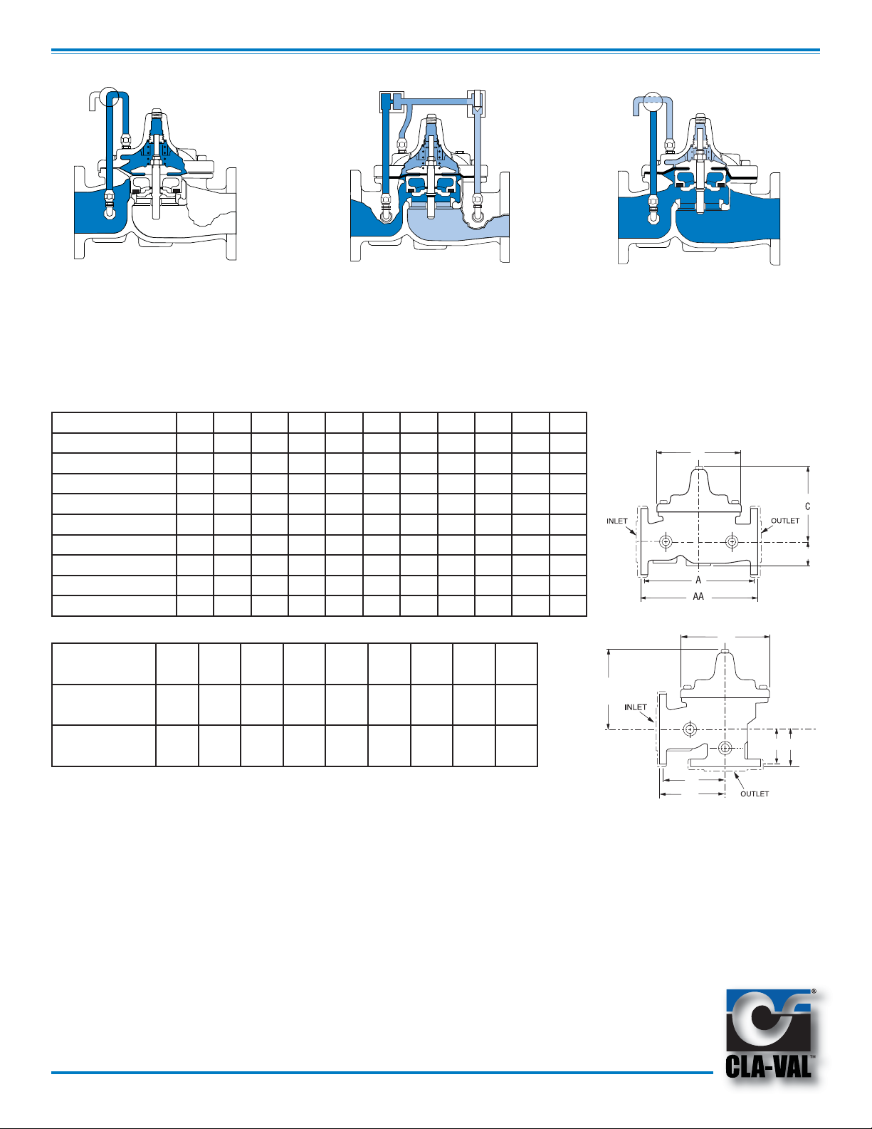
Principle of Operation
B
Tight Closing Operation
When pressure from the valve inlet
(or an equivalent independent
operating pressure) is applied to the
diaphragm chamber, the valve
Full Open Operation
When pressure in the diaphragm
chamber is relieved to zone of lower
pressure under the valve. Flow in
either direction is permitted.
closes drip-tight.
SIZE
A 125 &150 ANSI 8.50 9.38 11.00 12.00 15.00 20.00 25.38 29.75 34.00 39.00 41.38
AA 250 & 300 ANSI 9.00 10.00 11.62 13.25 15.62 21.00 26.38 31.12 35.50 40.50 43.50
B DIAMETER 5.62 6.62 8.00 9.12 11.50 15.75 20.00 23.62 28.00 32.75 35.50
C MAX. 5.50 6.50 7.56 8.19 10.62 13.38 16.00 17.12 20.88 24.19 25.00
D 1.12 1.50 1.69 2.06 3.19 4.31 5.31 9.25 10.75 12.62 15.50
E 125 & 150 ANSI - 4.75 5.00 6.00 7.50 10.00 12.75 14.88 17.00 19.50 20.81
EE 250 & 150 ANSI - 5.00 5.88 6.38 7.88 10.50 13.25 15.56 17.75 20.25 21.62
F 125 & 150 ANSI - 3.25 4.00 4.00 5.00 6.00 8.00 8.62 13.75 14.88 15.69
FF 250 & 300 ANSI - 3.50 4.31 4.38 5.31 6.50 8.50 9.31 14.50 15.62 16.50
1 1/2 2 2 1/2 3 4 6 8 10 12 14 16
CV Factor
Valve Size 1 1/2 2 2/ 1/2 3 4 6 8 10 12
100-34 GLOBE
PATTERN
26 49 80 107 200 440 771 1151 1600
Modulating Action
The valve modulates when
diaphragm chamber pressure is
held at a intermediate point between
inlet and discharge pressure
changes, the pressure above the
diaphragm is varied allowing the
valve to modulate and compensate
for the changes.
D
100AF
B
C
100-34 ANGLE
PATTERN
CV factor is defined as the number of gallons per minute of water at 60˚F. Which will flow at
a 60˚F. Which will flow at a one pound per square inch differential.
30 62 100 137 - - - - -
Purchase Specifications
The valve shall be hydraulically-operated, diaphragm-actuated, globe or angle pattern
valve. It shall contain a resilient, synthetic rubber disc, having a rectangular cross
section, contains on three and one-half sides by a disc retainer and disc guide,
forming a tight seal against a single renewable seat. The valve stem shall be guided
at both ends by a bearing in the valve cover and an integral bearing in the valve seat.
The diaphragm assembly shall be the only moving part and shall form a sealed
chamber in the upper portion of the valve, separating operating pressure from line
pressure. The diaphragm consist of nylon fabric bonded with synthetic rubber and
shall not be used as a seating surface. Packing glands and/or stuffing boxes are not
permitted and there shall be no pistons operating the valve. All necessary repairs
shall be possible without removing the valve from the line. If the diaphragm becomes
damaged the valve shall close tight. This valve shall be a Model 100-34 (globe pattern
or angle pattern) Hytrol Valve as manufactured by Cla-Val. Newport Beach, California.
E-40-30 (R-08/2012)
FFF
E
EE
Specify When Ordering
1. Size
2. Model 40-30 Globe or Angle
3. Pressure Class
4. Temperature and fluid to be handled
5. Static and flowing line pressure
6. Operating fluid and pressure
(if other than line pressure)
7. Body and trim materials
8. End details
 Loading...