

CLAUSING 1660, 1793, 16VC-1 SERIES, 16VT-1 SERIES Operating Instructions And Parts List Manual
. I
i
'
~
I
?f
OPERATING
PARTS
CLAUSING
INSTRUCTIONS
and
LIST
I
I
15-inch
DRILL
VARIABLE
MODELS
'
PRESses
SPEED.
DRIVE
·
..
I
r::!
~
CLAUSING·
-
2019 N. PITCHER ST., KALAMAZOO,
CD.RPDRATION
Ml
49007
. !
;
I
[
I
CLA.USING
CORPORATION
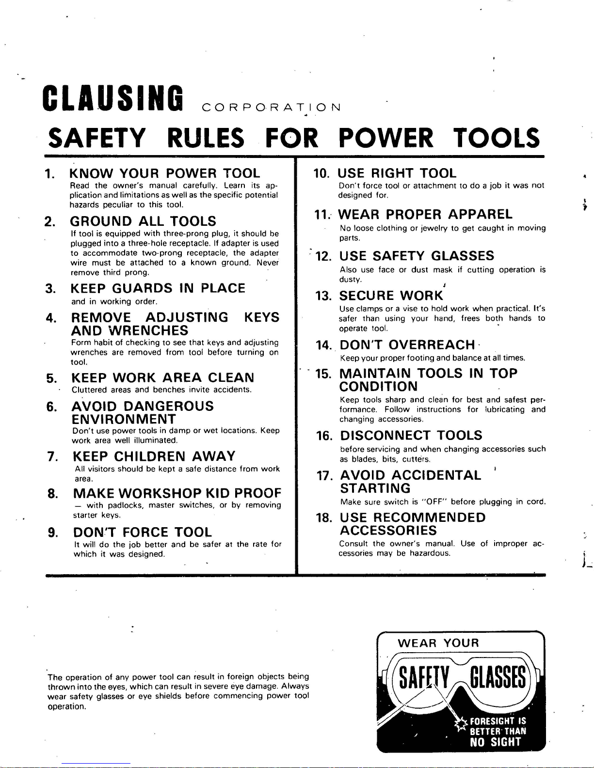
SAFETY
RULES
FOR
POWER
TOOLS
1.
2.
3.
4.
KNOW
YOUR
POWER
TOOL
Read
the
owner's
manual
carefully. Learn its ap·
plication
and
limitations
as
well
as
the
specific potential
hazards peculiar
to
this
tool.
GROUND
ALL
TOOLS
If
tool
is equipped
with
three-prong
plug,
it
should be
plugged
into
a three-hole receptacle .
If
adapter is used
to
accommodate
two-prong
receptacle,
the
adapter
wire
must
be attached
to a known
ground. Never
remove
third
prong
.
KEEP
GUARDS
IN
PLACE
and
in
working
order.
REMOVE
ADJUSTING
AND
WRENCHES
KEYS
Form
habit
of
checking
to
see
that
keys and adjusting
wrenches
are removed
from
tool
before
turning
on
tool.
5. KEEP
WORK
AREA
CLEAN
Cluttered areas and benches
invite
accidents.
6.
AVOID
DANGEROUS
ENVIRONMENT
Don't
use
power
tools in
damp
or
wet
locations. Keep
work
area
well
illuminated.
7. KEEP
CHILDREN
AWAY
All
visitors should be
kept
a safe distance
from
work
area.
8.
MAKE
WORKSHOP
KID
PROOF
-
with
padlocks, master switches,
or
by
removing
starter keys.
9.
DON'T
FORCE
TOOL
It
will
do
the
job
better
and
be safer
at
the
rate
for
which
it
was
designed.
The
operation
of
any
power
tool
can
result in foreign
object
s being
thrown
into
the
eyes,
which
can result
in
severe eye
damage. Always
wear
safety glasses
or
eye shields
before
commencing
power
tool
operation.
10.
USE
RIGHT
TOOL
Don't
force
tool
or
attachment
to
do a job
it
was
not
designed for.
11.-
WEAR
PROPER
APPAREL
No
loose
clothing
or
jewelry
to
get
caught
in
moving
parts.
:
12.
USE SAFETY GLASSES
Also use face
or
dust
mask
if
cutting
operation is
dusty.
J
13.
SECURE
WORK
Use clamps
or
a vise
to
hold
work
when
practical.
It's
safer than using
your
hand, frees
both
hands
to
operate tool.
14
..
DON'T
OVERREACH
·
Keep
your
proper
footing
and balance at all times.
15.
MAINTAIN
TOOLS
IN
TOP
CONDITION
Keep tools sharp
and
clean
for
best and safest per-
formance.
Follow
instructions
for
lubricating
and
changing accessories.
16.
DISCONNECT
TOOLS
before servicing
and
when
changing
accessories such
as
blades, bits,
cutters
.
17.
AVOID
ACCIDENTAL
STARTING
Make
sure
switch
is
"OFF"
before
plugging
in cord.
18.
USE
RECOMMENDED
ACCESSORIES
Consult
the
owner's
manual. Use
of
improper ac-
cessories
may
be hazardous.
WEAR
YOUR
I
j

...
~
INSTRUCTIONS
' !
DIVISION, ATLAS
KALAMAZOO,
LEVELING
Drill
press
should
shims
underneath
drill
press. Equal pressure should
tion
bolts
to
prevent
MICHIGAN
be
level
the
three
distorting
AND
PRESS
THE
DRILL
and
rest solidly
foundation
PARTS
COMPANY
49001
PRESS
on
holes
be
applied
the
base.
Boor; place
to
level
the
to founda-
FROM
JUNE
15"
VARIABLE
MODELS
SERIES-
SERIAL
1965
. . I
DRDILl
1660 THROUGH 1793
16VC-
IPRIESSES
.SPEED
1 - 16VT..; 1
No.
511742
FILE
. i
DRIVE
TO
5 5899
NO.
I
I
;
1.3
2.2
3. 3
4.1
5.1
6.3
7.1
8.1
8.2
RAISING HEAD
OPERATING
1.
To
position
side
of
2.
Slide
clamp handle.
3. Loosen set screw
column
set screws.
4.
To
position table, loosen
side
of
5. Slide table
clamp
drill
head
until
table.
handle.
drill
press.
up
it
up
column
touches
column
AND
POSITION
head, loosen
to
desired
in
safety collar
bottom
clamp
to
desired
TA -
clamp
of
Generally, the normal and most convenient position
for the
head is about
IMPORT
ANT:
8"
to 10" from
Always keep safety collar locked
· · under head.
LUBRICATION
Keep
QUILL
COLUMN
ered
with a light
of
oil_:_
FEED
grease
No. 1 bearing
- fittings
All
bearings
(C)
see Fig.
SHAFT
weekly
under
in
(A)
and
cov-
film
(1).
(B)
with
grease
head.
Figure
the head and lower quill
for-life ball bearings and do not require lubrication.
Occasionally
O~ce
a year, clean
(medium
ha
ndwheel (C, fig. 2
assemble
and
remove
move ha
out
center bolt.
1661
grease spinJle splines.
and
grease
cup
grease) cam
).
To
-loosen
ndwheel
plate
screw
(B);
by
taking
in
dis-
(A)
re
,
-
BLE
handle
height
and
head,
handle
height,
top
Figure
TO
and
slide
then
and
of
1
Me
2
on
tighten
it
tighten
on
right
tighten
column.
sealed-
left
up
' 1. Release
6. Replace
2.
1.3
Figure
ADJUSTING SPINDLE RETURN
To
increase tension,
the
spring
cap
out
spring
2.
While
hex
and
3. Loosen
4. Push
collar against
position.
Rotate
5.
DO
1.
When
depth,
pointer
r
tighten
Loosen
and
maximum travel,
podtion
pointer
then
screws {A, fig.
cap (fig:
ADJUSTING SPINDLE END PLAY[
spindle
holding
nut
on
quill
set
spindle
spindle
NOT
spindle -quill
setting
position
at
equired
nuts.
with
scale
is
at
tighten
assembly
screws
quill
lower
counter
bottom
screw
have
ADJUSTING DEPTH
depth
-
doc~wise.
3)
and
return
spindle
of
depth
from
in
collar directly above qJ ill.
firmly
against
top
of
by
hand
adjustment
drill
and
at
so
4%",
4)
.
3
SPRING
quill
to
bottom
To
release teAsion,
turn
clockwise.
S.pring·tension
to
prevent
stop
head. j
bottom
quill
and
to
make
too
assembly. . .
its
rod.
lock
sure
tight.
STOP
Figure
(fig.
falling
Remo\re
of q4ill
it
turns
1
4 ·
of
s~roke,
turn
pull
3).
, remove
spindle
. Force
coll~r
in
this
freely -
·
To
trol
change
until
CHANGING
speeds
pointer
on
shows desired speed.
SPINDLE
variable drive,
SPEEDS
turn
handwheel con-
CAUTION:
motor
1. With
700
is
running.
REPLACING VARIABLE
motor
rpm,
Do
then
not
running,
turn
off
turn
Figure
turn
motor.
handwheel
5
SPEED
variable
control
BELT
speed
unless
dial
to
Figure
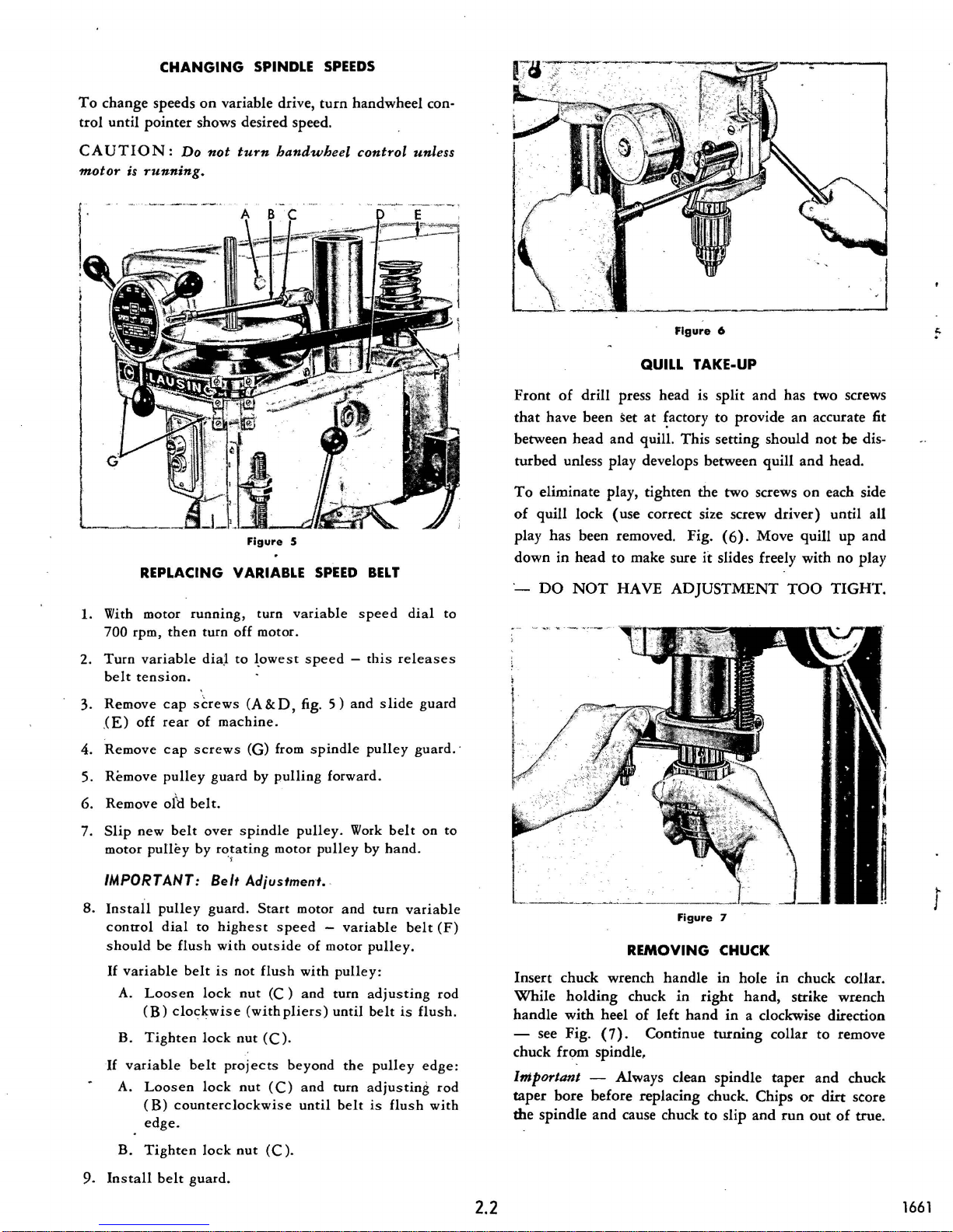
QUILL TAKE-UP
Front
of
drill
press head is
that
have
been
set
at
~actory
between
turbed
To
of
head
and
unless
play
eliminate play,
quill
lock
(use
quill.
This
develops between
tighten
the
correct size screw
play has been removed. Fig.
down
in
head
to
make sure
·-
DO
NOT
HAVE
it
ADJUSTMENT
6
split
and
has
to
provide
setting
should
quill
two
screws
driver)
(6).
Move
slides freely
two
an
accurate fit
not
and
on
quill
with
TOO
screws
be
dis-
head.
each side
until
all
up
and
no
play
TIGHT
.
2.
Turn
3.
4.
5.
6.
7.
variable
belt
tension.
Remove
.(E)
off
Remove
Remove
Remove
Slip
new
motor
pulley
cap
screws
rear
cap
pulley
ol\J
belt.
belt
dia
.l
of
machine.
screws
guard
over
by
rotating
to
~owest
(A & D,
(G)
by
spindle
)
IMPORTANT: Belt Adjustment.
8.
Install
control
s
If
If
hould
variable
A.
Loosen
(B)
B.
Tighten
variable
A.
Loosen
(B)
edge
pulley
dial
be
guard.
to
highest
flush
with
belt
is
not
lock
nut
clockwise
lock
nut
belt
proj
lock
nut
counterclockwise
.
Start
out
flush
(C)
(with
(C)
ects beyond
(C)
speed -this
fig. 5 )
from
spindle
pulling
pulley.
motor
motor
spee
d -
side
of
with
and
pliers)
.
and
until
and s !ide
forward.
Work
pulley
and
variable
motor
pulley:
turn
until
the
turn a
belt
releases
pulley
belt
by
hand.
turn
variabl
belt
pulley.
adjusting
belt
is
pulley
djusting
is
flush
guard
guard.·
on
to
(F)
rod
flush.
edge:
rod
with
e
REMOVING CHUCK
Insert
While
handle
- see Fig.
chuck
Important -
taper
the
chuck
holding
with
from
bore
spindle
wrench
chuck
heel
(7).
spindle,
Alw
before replacing chuck. Chips
and
cause chuck
Figure
handle
in
of
left
Continue
ays clean
right
hand
to
7
in
hole
in
chuck collar.
hand,
strike wrench
in
a clockwise direction
turning
spindle
collar
taper
or
slip
and
run
out
to
and
dirt
remove
chuck
score
of
true.
r
B.
Tighten
9.
Ins
tall belt
lock
guard.
nut
(C).
2.2
1661
 Loading...