


1
INDEX Section
General information ------------------------------------------------------------ 1
Dimensions ---------------------------------------------------------------------- 2
Installation Details -------------------------------------------------------------- 3
Electrical Connections -------------------------------------------------------- 4
Operation ------------------------------------------------------------------------- 5
Servicing & Maintenance ----------------------------------------------------- 6
41001456 Iss 01
R
ECESSED
W
ARM
C
EILING
H
EATERS
C
ATALOGUE NUMBERS
HE7230, HE7245, HE7260,
HE7230RX, HE7245RX, HE7260RX
I
NSTALLATION AND
O
PERATING
M
ANUAL
Consort Equipment Products Limited
Thornton Industrial Estate, Milford Haven
Pembrokeshire, SA73 2RT
Tel: 01646 692172 Fax: 01646 695195
Mon to Fri 8.30 am to 3.30 pm
Email: enquiries@consortepl.com Web: www.consortepl.com

2
1. General Information
1.1 Introduction
This instruction manual describes the CLAUDGEN
Recessed Warm Air Ceiling Heaters.
The heater is designed for discreet positioning in a
suspended 600mm ceiling within retail or commercial premises. It can fit a recess as shallow as
210mm.
1.2 General
All installations must be in accordance with the
regulations in force in the country of use.
These instructions must be handed to the user on
completion of the installation.
Installers and service engineers must be able to
demonstrate competence and be suitably qualified
in accordance with the regulations in force in the
country of use.
To ensure continued and safe operation it is
recommended that the appliance is serviced
annually.
The heater outlet / inlet must not be obstructed
during use.
1.3 Electrical Supply.
Electrical supply is 230/240V single phase, Neutral and Earth. The maximum cable inlet size is
4mm².
It is recommended that the electrical supply to the
base unit in the heater is via an appropriate
switched isolator in accordance with the
regulations in force in the country of use and must
be via a fused isolator having a contact separation
of greater than 3mm on all poles.
BMS control, time switches, room thermostats and
door interlocks can be installed at the discretion
and responsibility of the installer.
All units must be wired in accordance with I.E.E
regulations for the Electrical Equipment of
Buildings and the installer should ensure that a
suitable isolating switch is connected in the mains
supply.
1.4 Controller `RX` models
The HE7230RX, HE7245RX, HE7260RX heaters
are supplied without a controller. The `RX` models
will not work without the controller. See section
5.1 for more details.
1.5 Controller standard models
The HE7230, HE7245, HE7260 heaters are supplied with a remote controller. The remote control
unit houses 3 double pole 20A rocker switches.
The heater can also be controlled remotely via
BMS or any controls with contact rated at 20A for
HE7230, HE7245 and 30A for HE7260. The controller is wired to the base unit via an appropriate
sized cable specified by the current IEE standard.
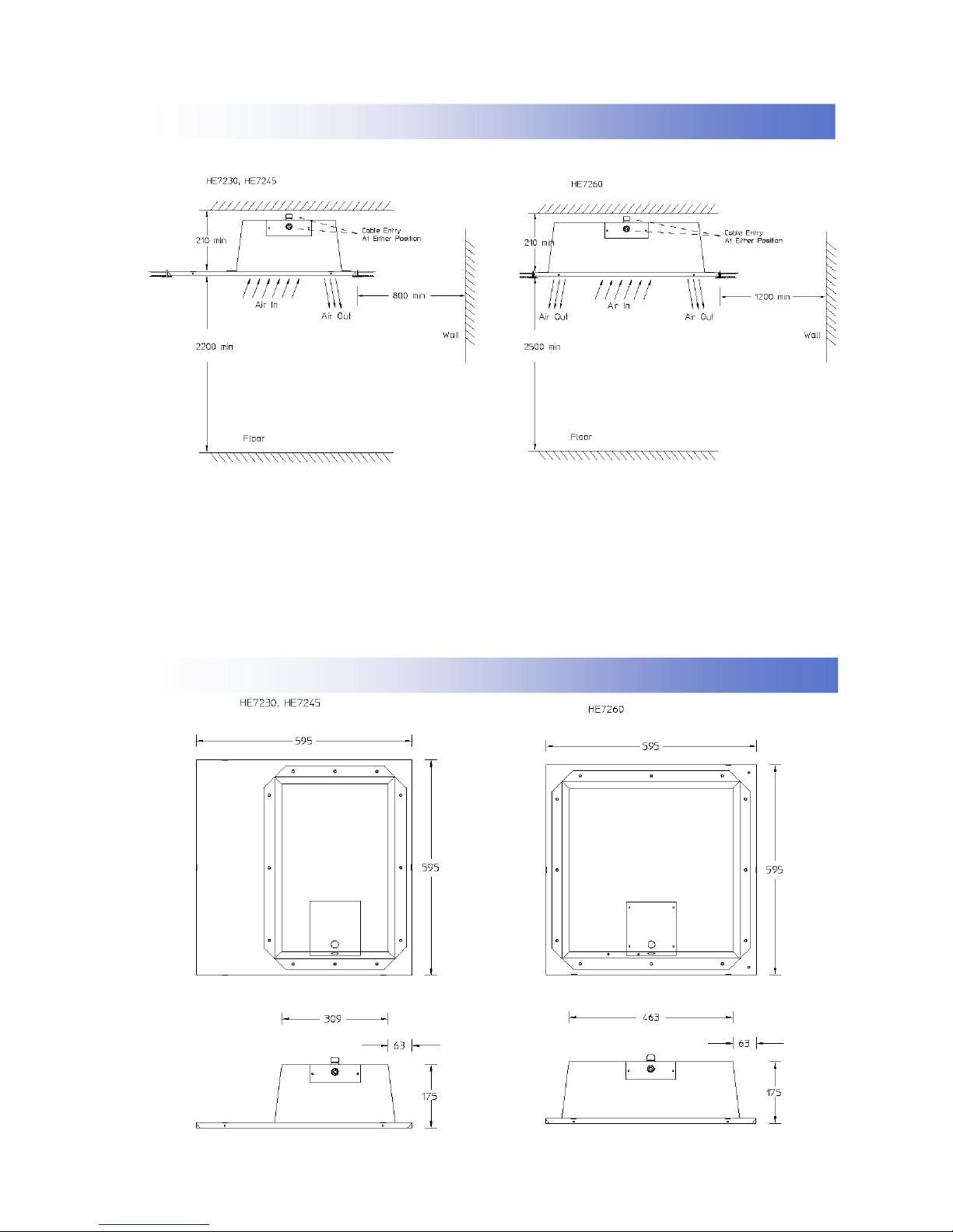
1.6 Location.
All units should be installed horizontally. It is recommended that the ceiling heater is installed
within the ceiling void or roof space.
Care must be taken to allow complete free air
movement into the inlet grilles of the unit to ensure
the correct working operation of the heater. If theHE7230 or HE7245 heaters are mounted close to
the wall or corner the discharge opening should
be facing the wall. The minimum distance from the
wall or corner is 0.8m or 1.2m for the HE7260.
1.7 Clearance distances
It is recommended that a minimum clearance of
50mm is allowed around the case and 30mm
above the heater. The clearance allows for cable
entry and prevents combustible surfaces overheating.
The minimum mounting height (floor to grille) is
2.2m for the HE7230, HE7245 and 2.5m for the
HE7260. The recommended mounting height is
2.5m for the HE7230, HE7245 and 3m for the
HE7260.
CONSORT Wireless controller CRX1
41001456 Iss 01
3
1.8 Clearance distances
1.9 Health and Safety
Sole liability rests with the installer to ensure that
all site safety procedures are adhered to during
installation.
Sole liability rests with the installer to ensure that
protective safety wear such as hand, eye, ear and
head protection is used during installation of the
product.
1. General Information
Do not rest anything especially ladders against the
product.
1.10 Standards
Units conform to the European electrical standard
BS EN 60335-2-30
2. Dimensions
41001456 Iss 01

4
ENSURE THE AIR OUTLET OF HE7230 AND
HE7245 IS NEAREST TO THE WALL OR CORNER.
3.1 Mounting
The Claudgen recessed ceiling heaters are designed to fit in place of a standard 600mm ceiling
panel.
IT IS ESSENTIAL THAT THE CEILING FRAME IS ADEQUATELY SUPPORTED TO SUPPORT THE WEIGHT OF THE
HEATER, OR THAT THE HEATER IS INDIVIDUALLY SUPPORTED. THERE IS PROVISION ON THE HEATER FOR
CHAIN OR WIRE, SUPPORT OR MOUNTING.
The weight of the HE7230/RX, HE7245/RX is 7kg
The weight of the HE7260/RX is 10kg
It is the sole responsibility of the installer to ensure
that the points of attachment to the building are
sound. Care must be taken to allow complete free
air movement into the inlet grilles of the unit to
ensure the correct working operation of the
heater. Carefully unpack the unit and control box.
The unit is supplied with a length of self-adhesive
foam strip. This can be cut into lengths and is to
be laid on the 4 sides of the ceiling frame . This
will ensure that the unit assembly is free from vibration. The discharge grille and diffuser assembly can now be fitted into the ceiling frame.
4.1 Electrical Connections.
These units are suitable for connection to a
230/240 Volt 50 Hz single phase supply.
The appliance shall be connected to the supply
via an appropriate switched fused double pole
isolator having a contact separation of greater
than 3mm. Test for correct operation and refit the
cover.
3. Installation Details.
Fig.1 Air discharge of HE7230/RX and HE7245/RX
Fig.2 Air discharge of HE7260/RX
TOP OR SIDE CABLE ENTRY
TERMINAL COVER
For connection to the mains supply it will be
necessary to open the terminal cover at the side/
back of the unit to connect the supply from the
controls prior to refitting the cover. Wire in accordance to the wiring diagrams.
For safety reasons, a sound earth connection
must always be made to the unit before it is put to
use. The unit should be wired in accordance with
IEE Regulations for the Electrical Equipment of
Buildings.
4. Electrical Connections.
41001456 Iss 01
Fig.3 Mounting supports
The wire or chain used to mount the heater can be
attached to 4 of the M6 studs or the 4 x M6
threaded inserts as shown in diagram.

5
4. Electrical Connections.
4.2 Electrical connections for standard models
Fig.6 Mains supply via remote switch
N L
E
N and E connected by 30A
one way connector block
Fig.7 Wiring of the heaters without using remote switch
4.3 Electrical connections without using the remote switch standard models
If the heaters are to be controlled by means other than the remote switch supplied, eg BMS, then
the heat output can be selected by connecting the appropriate terminals.
WIRED TERMINALS
HE7230 HE7245 HE7260
H1 + H2 + F
3000W 4500W 6000W
H1 + F
1000W 1500W 2000W
H2 + F
2000W 3000W 4000W
Please note the ‘F’ terminal must always be connected
F - Fan
H1 - Heating element 1
H2 - Heating element
N - Neutral
E - Earth
41001456 Iss 01
Fig.5 Remote switch terminal side view Fig.4 Mains supply direct to heater
N L E
L L
L connected by 30A
one way connector block
L L
L1
Two independent live
feeds must be used on
4,5kW and 6kW heaters as
shown on the diagrams

6
5.1 Models for wireless controls
The heaters for wireless controls, models
HE7230RX, HE7245RX and HE7260RX can be
controlled by CONSORT wireless controller
CRX1. The heaters will not work without a
controller. Each controller has unique identification
code, it can control unlimited number of heaters
and will not interfere with other controllers within
the building. For more details please follow the
instructions supplied with the controller.
5.2 Standard models
All standard heaters
HE7230, HE7245 and HE7260 are supplied with a
remote switch that gives the following functions;
On/off & two heat settings.
For thermostatic control a room thermostat of
appropriate switch rating maybe connected to the
circuit. The thermostat should be wired between
the isolator switch and the heater remote switch.
For HE7245, HE7260 or to control more than one
HE7230 heaters by a thermostat, a contactor or a
relay in conjunction with the thermostat should be
used.
5. Operation.
4. Electrical Connections.
4.4 Electrical connections for wireless control models
Fig.8 Heater with terminal cover open Fig.9 Terminal cover detail
To switch on the appliance and operate the
blower, depress the left-hand switch (marked
“FAN”).
When the centre switch only (marked with a single
bar) is depressed the heat output is ⅓ of full heat.
HE7230 - 1kW, HE7245 - 1.5kW, HE7260 - 2kW
When the right hand switch only (marked with a
double bar) is depressed the heat output is ⅔ of
full heat.
HE7230 - 2kW, HE7245 - 3kW, HE7260 - 4kW
When both the centre switch and
the right-hand switch are depressed the full heat
output is available.
HE7230 - 3kW, HE7245 - 4.5kW, HE7260 - 6kW
41001456 Iss 01

7
Consort Equipment Products Ltd
Registered Office: Thornton Industrial Estate
Milford Haven, Pembrokeshire, SA73 2RT
Tel: 01646 692172 Fax: 01646 695195
BS EN ISO 9001 Registered Company No FM12671
ALWAYS ENSURE THAT THE MAIN
EXTERNAL ELECTRICITY SUPPLY IS
SWITCHED OFF BEFORE COMMENCING ANY
MAINTENANCE ON THIS HEATER.
To obtain the best results from the heater, it is
essential to avoid the accumulation of dust and
dirt within the unit on the air inlet and discharge
grilles. For this reason regular cleaning is
necessary.
Cleaning of the fan is best carried out with a soft
brush.
The product should be serviced annually.
Servicing shall be undertaken by a competent
person.
6.2 General
If the heater does not operate a competent service
engineer should be called to identify the nature of
the fault.
All heaters are fitted with motor thermal protection.
Other faults in relation to the element, motor and
wiring should be identified using conventional fault
finding techniques.
In the event that electrical components are
replaced, please ensure that electrical safety
checks in accordance with the regulations in force
in the country of use are undertaken.
6.3 Thermal cut-out
The units are protected from overheating in the
event of fan failure or an obstruction of the free
airflow, by thermal cut outs. If this happens the
thermal cut outs switch off the appliance. The appliance will not operate until the heater is disconnected from the mains supply and it has cooled
down.
If this fault re-occurs again, refer to the section
‘6.4 fault finding’.
6. Servicing & Maintenance.
6.1 Maintanence
6.4 Fault Finding
If the heater will not operate, disconnect it from
the mains and arrange for a certified electrician to
attend and investigate the reason.
6.5 Replacing the Fan Heater
a) Remove the grille.
b) Disconnect the internal wiring from the blower
c) Remove the four screws fixing the fan heater
assembly to the back of the case.
d) The fan heater assembly can now be eased
forward and removed from the heater case.
e) Fit replacement fan heater and reassemble in
reverse order.
6.6 Spares
It is essential when ordering spares or replacement parts to state the model number and the
serial number on the rating label fixed to the side
of the unit below the terminal cover.
In the interest of progress the Company reserve
the right to vary specifications from time to time
without notice. The material listed is offered subject to the Company’s General Conditions of Sale,
a copy of which can be obtained on request.
41001456 Iss 01

8
 Loading...