

Page 1
44000070 Iss 04
Consort Equipment Products Ltd
Registered Office: Thornton Industrial Estate
Milford Haven, Pembrokeshire, SA73 2RT
Tel: 01646 692172 Fax: 01646 695195
BS EN ISO 9001 Registered Company No FM12671
INSTALLATION, OPERATION AND MAINTENANCE INSTRUCTIONS FOR
Heat-Zone Fan Heater
FOR WIRELESS CONTROLS
Catalogue Numbers: HE7010RF 3 kW 230/240V
PLEASE RETAIN THIS LEAFLET FOR FUTURE MAINTENANCE
MODEL
Heat-Zone is a quiet Fan Heater designed for Commercial and
Industrial situations, and is suitable for mounting on the wall.
The Heat-Zone incorporates a tangential flow fan and the unit is
designed to operate in free air conditions. It is important that
there should be no restriction on the free flow of air through the
unit. When installed the top of the heater case should be a
minimum of 200mm from the ceiling.
MOUNTING
The normal mounting height is 2.3m above the floor, although
this will depend to some extent on the situation.
The heater can be positioned to blow air at any angle, from
horizontal to vertically downwards, subject to the conditions
mentioned below. It is suggested that an angle of 450 is a
convenient starting point when setting up the unit.
It must always be installed with the axis of the motor horizontal.
Failure to ensure this will result in excessive bearing wear and
premature failure.
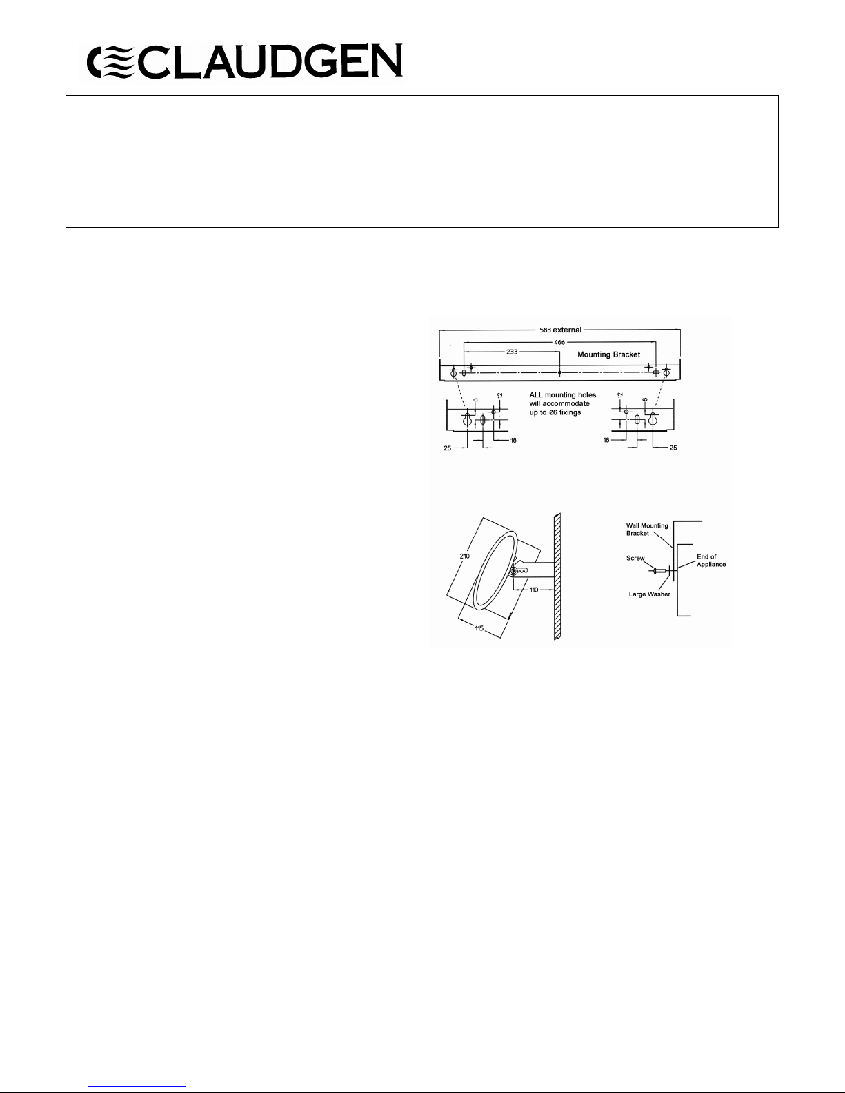
A mounting bracket is provided for mounting on a wall.
The heater should not be mounted in situations where it may be
subject to conditions of excessive humidity or the atmosphere is
corrosive.
INSTALLATION
To the unit connect a suitable length of 3 or 4 core flexible
cable to the input terminal block.
Loosen mounting screws, allowing the mounting bracket to be
removed from the unit. Making sure that the mounting bracket
is horizontal, fix the bracket to the wall using 3 x No 8 wood
screws.
Place the unit on the mounting bracket ensuring the washers are
spaced as on diagram (a plain washer either side of the
mounting bracket).
Tighten screws to hold the unit at the required angle.
ELECTRICAL CONNECTIONS
These units are suitable for connection to a 230/240V 50Hz
single phase ac supply. The units consume 3kW of electrical
power when the fan and heater are in operation.
To connect a supply to the heater, first remove the top cover by
unscrewing the 4 fixing screws (2 either side), then lifting off
the cover. The input terminal block, marked NFH, is fitted at
the left hand side of the unit looking from above (at the
opposite end to the fan motor).
A double-pole isolator switch should be included in the
installation.
Page 2

44000070 Iss 04
OPERATION
This heater is controlled by a Celsia Zone Controller CZC1 and
can only be used when connected. Each CZC1 can control any
number of heaters. The heater has an indicator light positioned
on the fascia panel on the top left side. The light may be:
Green - when no heat is needed
Yellow - when some heat is needed to maintain
the room temperature
Red - when the heater is on full power
Fast Flashing Red - when the heater has overheated and an
Electronic Safety Control has switched
the heater off.
Please refer to the user and operating instructions for the CZC1
for detailed instructions.
ELECTRONIC SAFETY CONTROL
The appliance is fitted with an Electronic Safety Control (ES).
This is a safety device which switches the heater off if, for any
reason, the appliance overheats. The overheating is indicated
by fast flashing red light. The ES control can only be re-set
after the appliance has cooled down. In order to re-set the ES
control, proceed as follows:
• Switch the appliance off at the mains by using the isolator
switch and leave to cool down for approximately 5 minutes.
• Switch appliance back on and the ES control will re-set.
• Ensure that the appliance is functioning correctly. If the ES
control operates again, the appliance should be checked by
a competent electrician.
MAINTENANCE
ALWAYS ENSURE THAT THE MAIN EXTERNAL ELECTRICITY SUPPLY
IS SWITCHED OFF BEFORE ATTENDING TO THE SERVICING OF THE
UNIT.
To obtain the best results from Heat-Zone it is necessary to
avoid any build-up of dust or dirt within the unit or on the air
inlet grille. For this reason the unit should be cleaned regularly,
paying particular attention to the removal of dirt build-up on
the back of the fan rotor blades.
The removal of dust and dirt is best achieved using a soft
brush.
TO REMOVE THE FAN HEATER ASSEMBLY
a) Remove the top cover as described under the heading
‘Electrical Connection’.
b) Disconnect the supply wires to the input terminal block and
earth post.
c) Unscrew the bush holding the terminal block assembly to
the main case.
d) Remove the 4 nuts and washers holding the fan heater
assembly in place.
e) The fan heater assembly, terminal block and internal wiring
can now be removed.
The assembly is replaced by carrying out the above operations in
the order e) to a).
SPARES
It is essential when ordering spares or replacement parts to
state the model number and serial number on the rating plate
fixed to the top of the unit.
In the interest of progress the Company reserves the right to
vary specifications from time to time without notice. The
material listed is offered subject to the Company’s General
Conditions of Sale, a copy of which may be obtained by request.
 Loading...